

Page 1
subzero.com 800.222.7820
400
Service Manual
General Information 2
Installation Information 10
Controls & Operation 30
Page 2
General Information
Wine Storage
Wine Storage
(400-
(400-
2
2
)
)
Series
Series
1-2
#3758410 - Revision C - May,2014
IMPORTANT SAFETY INFORMATION
Below are Product Safety Labels used in this manual.
The "Signal Words" used are WARNING or CAUTION.
When reviewing this manual, please note these different Product Safety Labels placed at the beginning of
certain sections of this manual. You must follow the
instructions given in the boxes of the Product Safety
Labels in order to avoid personal injury and/or product
damage.
The sample Product Safety Labels below illustrate the
precautions that should be taken when the signal word
is observed.
INTRODUCTION
This Technical Service Manual has been compiled to provide the most recent service information for 400-2 Series
units. This information will enable the service technician to troubleshoot and diagnose malfunctions, perform necessary repairs, and return a unit to proper operational condition.
The service technician should read the complete instructions contained in this manual before initiating any repairs on
a 400-2 Series unit.
INDICATES THAT HAZARDOUS OR UNSAFE PRACTICES COULD RESULT IN SEVERE PERSONAL
INJURY OR DEATH.
Indicates that hazardous or unsafe practices could
result in minor personal injury, and/or product damage, and/or property damage.
In addition, please pay attention to the signal word
“NOTE”, which highlights information that is especially
important for the topic being covered.
This manual is designed to be used by Authorized Service Personnel only. Sub-Zero Freezer Co., Inc.
assumes no responsibility for any repairs made on Sub-Zero refrigeration units by anyone other than
Authorized Service Technicians.
Information and images contained in this manual are the copyright property of Sub-Zero Freezer Company, Inc.
Neither this manual nor any information or images contained herein may be copied or used in whole or in part
without the express written consent of Sub-Zero Freezer Company, Inc.
© Sub-Zero Freezer Company, Inc, all rights reserved.
TECHNICAL ASSISTANCE
If you should have any questions regarding a Sub-Zero
appliance and/or this manual, please contact:
Sub-Zero, Inc.
ATTN: Service Department
P.O. Box 44988
Madison, WI 53744-4988
Customer Assistance
Phone #: (800) 222 - 7820
Facsimile #: (608) 441 - 5887
Technical Assistance
(For Technicians in Customer’s Homes Only)
Phone #: (800) 919 - 8324
Parts / Warranty Claims
Phone #: (800) 404 - 7820
Facsimile #: (608) 441 - 5886
Service Department e-mail Address:
customerservice@subzero.com
Main Office Hours:
8:00 AM to 5:00 PM Central Time
Monday through Friday
(24/7 Phone Coverage)
Page 3
Wine Storage
Wine Storage
(400-
(400-
2
2
)
)
Series
Series
General Information
1-5
#3758410 - Revision C - May,2014
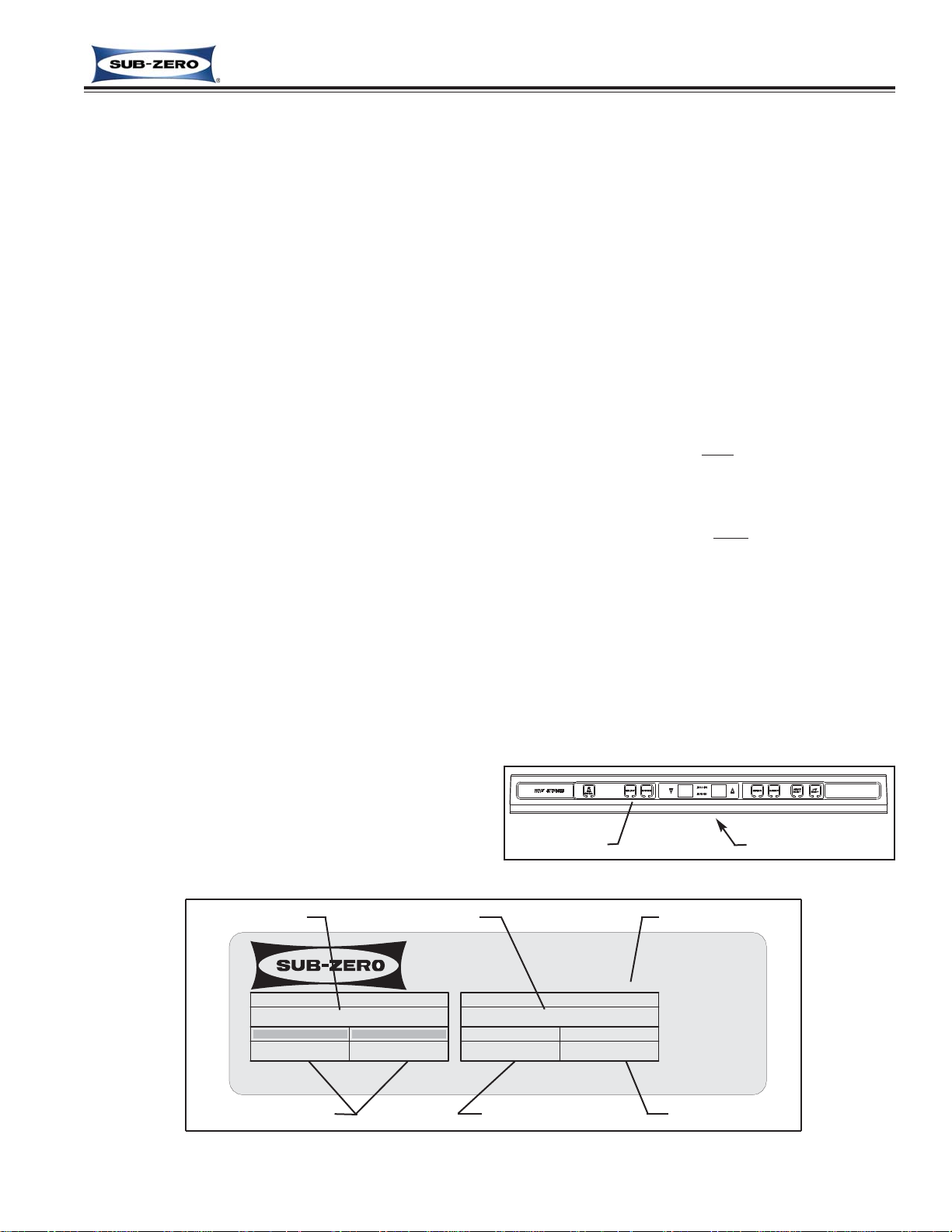
Figure 1-2. Serial Tag Layout
Serial Tag LocationControl Panel
Figure 1-1. Serial Tag Location
424G / O 2
2191621
0.0
3.5 1.8 R134a
Jan 2005
Model Number
Serial Number
Manufacture Date
Refrigerant Charge
Total Amps Refrigerant Type
WINE
WARRANTY INFORMATION
This page summarizes the 2, 5 & 12 Year Warranty pro-
vided with every 400-2 Series unit, as well as two special warranties:
• Non-Residential Warranty - Applies to units installed
in non-residential applications.
• Display/Model Home Warranty - Applies to distribu-
tor or dealer display units, and units in model
homes, sold three years after date of manufacture.
Following the warranty summaries are details and notes
about the warranties.
TWO, FIVE & TWELVE YEAR Warranty
• 2 year TOTAL PRODUCT, *parts and labor.
NOTE: Stainless Steel (Classic, carBon & Platinum)
doors, panels & product frames are covered by a 60
day parts & labor warranty for cosmetic defects.
• 5 Year SEALED SYSTEM, **parts and labor.
• 6th - 12th year LIMITED SEALED SYSTEM, **parts
only.
ONE & FIVE YEAR Non-Residential Warranty
(Example: Office, Yacht, etc.)
• 1 Year TOTAL PRODUCT, *parts and labor.
NOTE: Stainless Steel (Classic, carBon & Platinum)
doors, panels & product frames are covered by a 60
day parts & labor warranty for cosmetic defects.
• 5 Year SEALED SYSTEM, **parts only.
ONE & FIVE YEAR Display/Model Home Warranty
(Display units sold three years after date of manufacture)
• 1 Year TOTAL PRODUCT, *parts and labor.
NOTE: Stainless Steel (Classic, carBon & Platinum)
doors, panels & product frames are covered by a 60
day parts & labor warranty for cosmetic defects.
• 5 Year SEALED SYSTEM, **parts only.
Warranty Details
* Includes, but is not limited to the following:
Electronic Control System Components, Fan & Light
Switches, Fan Motors & Blades, Defrost & Drain
Heaters, Defrost Terminator, Drain Pan, Drain Tubes,
Wiring, Light sockets & bulbs, Door hinges, Door
closers & Cams, Compressor Electricals, etc. . .
* Stainless Steel (Classic, Platinum & Carbon) doors,
panels and product frames are covered by a limited 60
day parts and labor warranty for cosmetic defects.
** Includes the following:
Compressors, Condenser, Evaporators, Filter-Driers,
Refrigerant Valve Assembly, Heat-exchangers, All
Tubing that Carries the Freon.
NOTE: Condenser Fan Motors, Freon, Solder and
compressor electricals are NOT
considered sealed
system parts.
Warranty Notes
• All warranties begin at unit's initial installation date.
• All Warranty and Service information collected by SubZero is arranged and stored under the unit serial number, and the customer's last name.
Sub-Zero requests that you have the model and serial
number available whenever contacting the factory or
parts distributor.
• The serial number tag for models 427-2, 427R-2, and
430-2 is located on the bottom side of the compartment
divider, directly behind the control panel. (See Figures
1-1, 1-2) For model 424-2 it is on the upper compartment ceiling (not shown).
MODEL
FREEZER CO., INC.
FREEZER REFRIGERATOR
PRODUCT SERVICE 1-800-222-7820
LISTED HOUSEHOLD
REFRIGERATOR OR FREEZER
MADISON, WI
SERIAL NUMBER
TOTAL AMPS
115Vac, 60Hz, 1 Phase
REFRIGERANT
Page 4
General Information
Wine Storage
Wine Storage
(400-
(400-
2
2
)
)
Series
Series
1-6
#3758410 - Revision C - May,2014
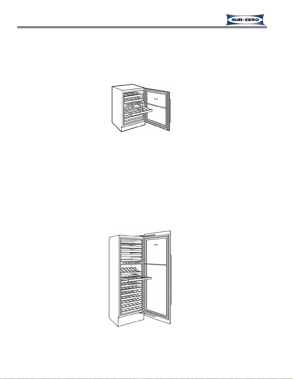
MODEL DESCRIPTIONS
This section briefly describes the models covered in this 400-2 Series Technical Service Manual. There are four
basic model configurations (Models 424-2, 427-2, 427R-2, and 430-2), with esthetic variations of the exterior cosmetic components. This manual will address the four basic configurations in most cases.
The following diagrams (Figures 1-3 to 1-6) explain the 400-2 Series model numbering system.
424G/B-2 • 400 Series - 24” Wide - Glass/CarBon (or Black) Steel Wrapped Door
424HAG/B-2 • 400 Series - 24” Wide - High Altitude Glass/CarBon (or Black) Steel Wrapped Door
424G/O-2 • 400 Series - 24” Wide - Glass/Overlay Panel Application Door
424HAG/O-2 • 400 Series - 24” Wide - High Altitude Glass/Overlay Panel Application Door
424G/P-2 • 400 Series - 24” Wide - Glass/Platinum Steel Wrapped Door
424HAG/P-2 • 400 Series - 24” Wide - High Altitude Glass/Platinum Steel Wrapped Door
424G/S-2 • 400 Series - 24” Wide - Glass/Stainless Steel Wrapped Door
424HAG/S-2 • 400 Series - 24” Wide - High Altitude Glass/Stainless Steel Wrapped Door
424S/B-2
• 400 Series - 24” Wide - Solid/CarBon (or Black) Steel Wrapped Door
424S/O-2 • 400 Series - 24” Wide - Solid/Overlay Panel Application Door
424S/P-2 • 400 Series - 24” Wide - Solid/Platinum Steel Wrapped Door
424S/S-2 • 400 Series - 24” Wide - Solid/Stainless Steel Wrapped Door
424FS/G-2 • 400 Series - 24” Wide - Free Standing - Stainless Steel Wrapped Unit - Glass Door
424FS/HAG-2 • 400 Series - 24” Wide - Free Standing - Stainless Steel Wrapped Unit - High Altitude Glass Door
424FS/S-2 • 400 Series - 24” Wide - Free Standing - Stainless Steel Wrapped Unit - Solid Door
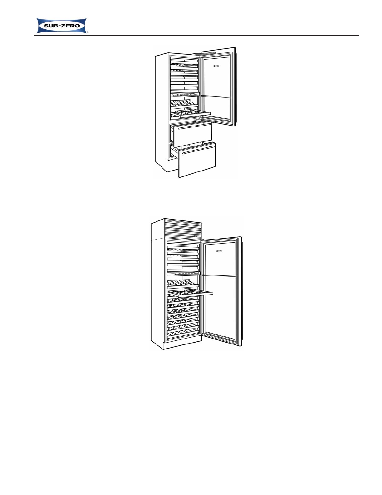
427G-2 • 400 Series - 27” Wide - Glass Door
427HAG-2 • 400 Series - 27” Wide - High Altitude Glass Door
427S-2 • 400 Series - 27” Wide - Solid Door
Figure 1-3. Model 424-2
Figure 1-4. Model 427-2
NOTE: Door panels for this model sold
separately.
Page 5
Wine Storage
Wine Storage
(400-
(400-
2
2
)
)
Series
Series
General Information
1-7
#3758410 - Revision C - May,2014
427RG-2 • 400 Series - 27” Wide - Refrigerated Drawers - Glass Door on Wine Storage Section
427RHAG-2 • 400 Series - 27” Wide - Refrigerated Drawers - High Altitude Glass Door on Wine Section
427RS-2 • 400 Series - 27” Wide - Refrigerated Drawers - Solid Door on Wine Storage Section
Figure 1-5. Model 427R-2
Figure 1-6. Model 430-2
430G/B-2 • 400 Series - 30” Wide - Glass/CarBon (or Black) Steel Wrapped Door
430HAG/B-2 • 400 Series - 30” Wide - High Altitude Glass/CarBon (or Black) Steel Wrapped Door
430G/F-2 • 400 Series - 30” Wide - Glass/Framed Panel Application Door
430HAG/F-2 • 400 Series - 30” Wide - High Altitude Glass/Framed Panel Application Door
430G/O • 400 Series - 30” Wide - Glass/Overlay Panel Application Door
430HAG/O-2 • 400 Series - 30” Wide - High Altitude Glass/Overlay Panel Application Door
430G/P-2 • 400 Series - 30” Wide - Glass/Platinum Steel Wrapped Door
430HAG/P-2 • 400 Series - 30” Wide - High Altitude Glass/Platinum Steel Wrapped Door
430G/S-2
• 400 Series - 30” Wide - Glass/Stainless Steel Wrapped Door
430HAG/S-2 • 400 Series - 30” Wide - High Altitude Glass/Stainless Steel Wrapped Door
430S/B-2 • 400 Series - 30” Wide - Solid/CarBon (or Black) Steel Wrapped Door
430S/F-2 • 400 Series - 30” Wide - Solid/Framed Panel Application Door
430S/O-2 • 400 Series - 30” Wide - Solid/Overlay Panel Application Door
430S/P-2 • 400 Series - 30” Wide - Solid/Platinum Steel Wrapped Door
430S/S-2 • 400 Series - 30” Wide - Solid/Stainless Steel Wrapped Door
NOTE: Door panels for this model sold
separately.
Page 6
General Information
Wine Storage
Wine Storage
(400-
(400-
2
2
)
)
Series
Series
1-8
#3758410 - Revision C - May,2014
Wine Storage Unit Maximum Temperature 65° 18°
Sub-Zero Wine Storage Temperature Range, Recommended Wine Storage Temperatures
and Recommended Wine Serving Temperatures:
Bordeaux 63° 17°
Red Burgundy 61° 16°
Beaujolais 54° 12°
Sherry 52° 11°
Rosés 48° 9°
Dry White Wines 48° 9°
Champagne 46° 8°
Sweet White Wines 43° 6°
Sparkling Wines 41° 5°
Wine Storage Unit Minimum Temperature 38° 3°
Fahrenheit Celsius
The table below shows the temperature range of the Sub-Zero Wine Storage Units. This table also shows the rec-
ommended temperatures for “serving” wines. Serving wines at the recommended temperatures will insure that white
wines maintain their lively and interesting taste, and red wines will maintain their scent and flavor.
NOTE: For “long term storage” of all wines, the ideal temperature is 55°F / 13°C.
NOTE: The temperature range in the refrigerator drawer area of the 427R is 34°F / 1°C to 45°F / 7°C.
Recommended Wine Serving Temperatures
Page 7
Installation Information
Wine Storage
Wine Storage
(400-
(400-
2
2
)
)
Series
Series
2-2
#3758410 - Revision C - May, 2014
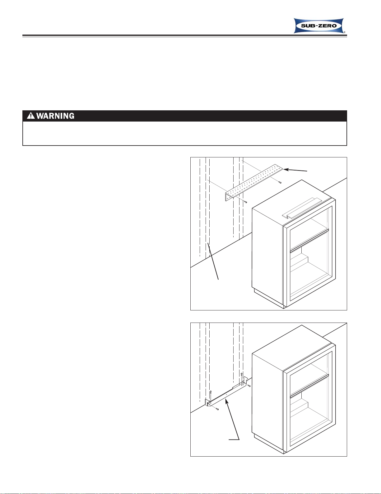
Anti-Tip Components Installation (424-2)
If anti-tip bracket needs to be installed, follow these
steps (See Figure 2-1):
1. Locate and mark two wall studs at back of unit
installation location.
2. Identify and mark proper height to clear unit top.
Space between unit top and bottom of bracket must
NOT be more then 1/4" (6.1 mm)
3. Secure bracket to wall studs, located in step 1, making sure screws extend 7/8" (22.2 mm) into each
wall stud. The bracket must extend a minimum of 3"
(76.2 mm) over unit.
4. Refer to Installation Guide provided with unit for any
additional information needed.
Anti-Tip Components Installation
(424FS-2, 427-2, 427R-2)
If anti-tip bracket needs to be installed, follow these
steps (See Figure 2-2):
1. Center anti-tip bracket at back of unit installation
location.
2. Secure bracket to wall studs or flooring, making sure
screws extend 7/8" (22.2 mm) into each wall stud or
flooring.
3. Refer to Installation Guide provided with unit for any
additional information needed.
INSTALLATION CONSIDERATIONS
This section covers common installation issues seen by Service Technicians. Improper installation, though not a
valid service issue, has the potential to lead to a call for service. Installation related complaints could include, but
are not limited to: Unit leveling, unit movement, door misalignment, improper door and drawer sealing, internal frost
or condensation, exterior condensation, warm compartment temperatures, etc.
NOTE: If additional installation information is needed, refer to the complete Installation Guide, or contact Sub-Zero
Service Department.
UNIT COULD TIP UNDER CERTAIN LOAD CONDITIONS. FAILURE TO INSTALL ANTI-TIP COMPONENTS AND
EXTEND FRONT LEVELERS TO FLOOR ACCORDING TO INSTALLATION MANUAL CAN RESULT IN SERIOUS
INJURY OR DEATH.
Figure 2-1. Anti-Tip Components
Wall Stud
Bracket
Figure 2-2. Anti-Tip Components
Bracket
Page 8
Wine Storage
Wine Storage
(400-
(400-
2
2
)
)
Series
Series
Installation Information
2-3
#3758410 - Revision C - May, 2014
Sub-Zero Unit
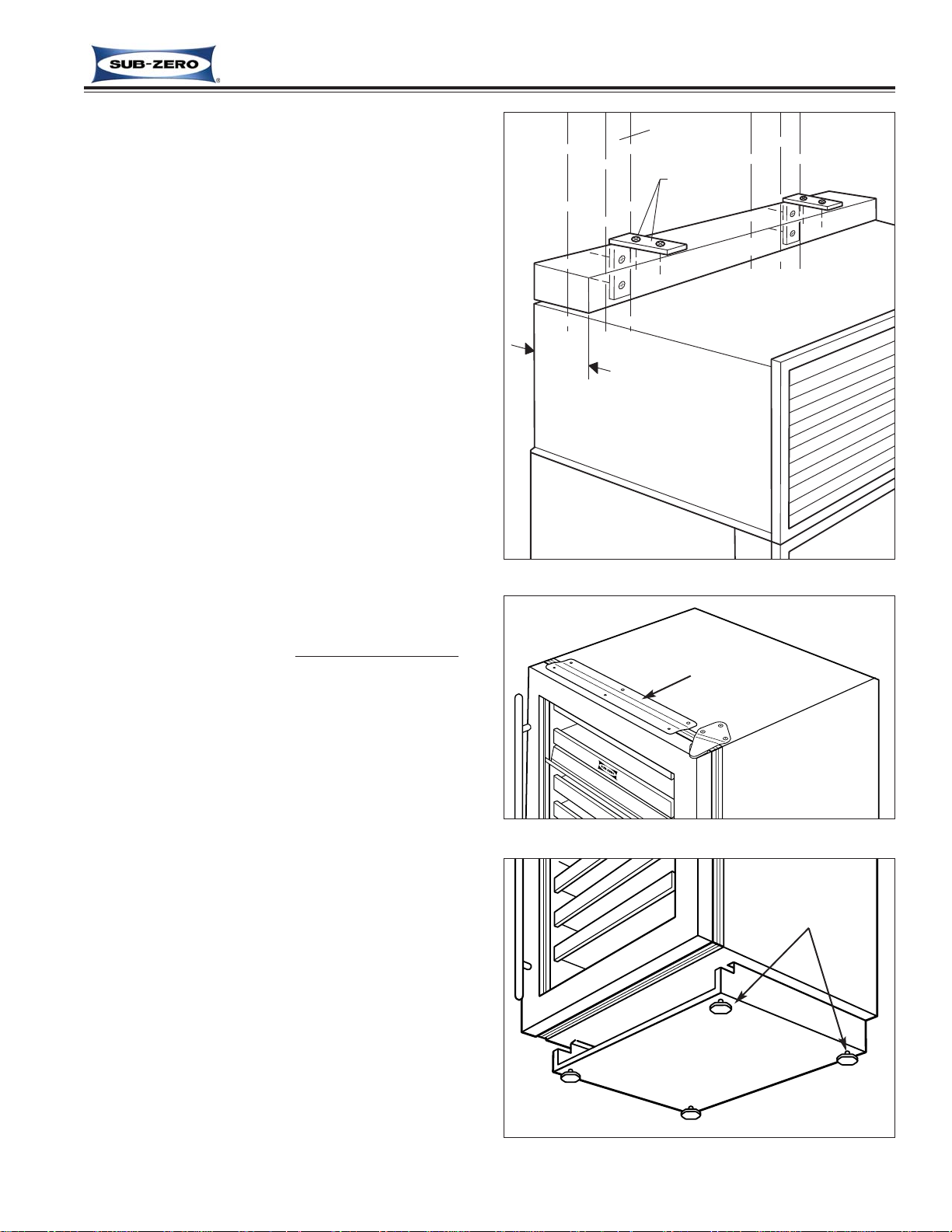
Figure 2-3. Anti-Tip Components
Wall Stud
Wood Block
Screws &
L-Bracket
Min. 3”
(76.2 mm)
Anti-Tip Components Installation (430-2)
If anti-tip components (aka wood block / blocking kit)
need be installed, follow these steps (See Figure 2-3):
1. Locate and mark two wall studs at back of unit
installation location.
2. Identify and mark proper height to clear unit top.
Space between unit top and bottom of wood block
must NOT be more then 1/4" (6.1 mm).
3. Using the L-brackets and screws provided, secure
wood block to wall studs, located in step 1, making
sure screws extend 7/8" (22.2 mm) into each wall
stud. The wood block must extend a minimum of 3"
(76.2 mm) over unit.
4. Utilizing front and rear levelers, raise and level unit
until it contacts wood block (See leveling instructions
on following pages).
5. Refer to Installation Guide provided with the unit for
any additional information needed.
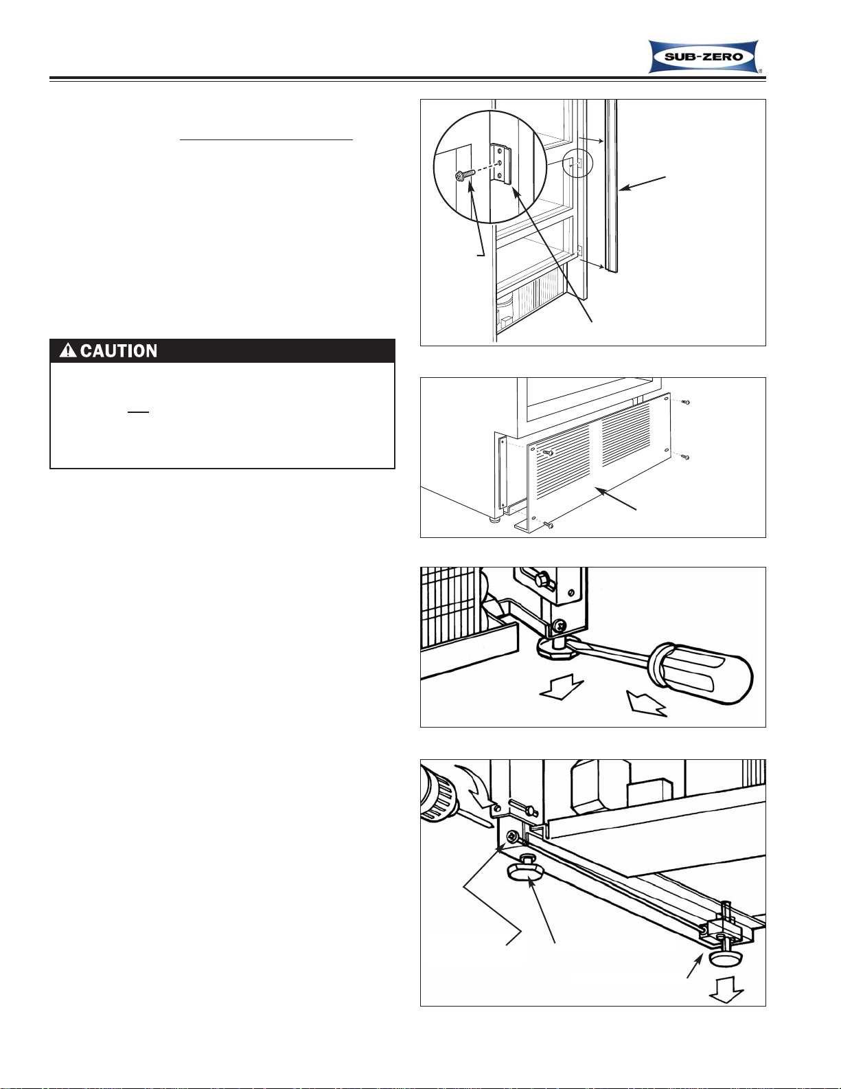
Unit Leveling (424-2, 424FS-2)
NOTE: Model 424-2 must be leveled before installing
into rough-in opening. If unit is already installed and
anchored with countertop bracket (See Figure 2-4),
Extract anchor screws before leveling, reinstalled after.
To Level 424-2 - Place it in front of rough-in opening,
then turn each leveling leg clockwise to raise unit, counterclockwise to lower unit (See Figure 2-5).
To Level 424FS-2 - Turn each leveling leg clockwise
to raise unit, counterclockwise to lower unit (See Figure
2-2).
Figure 2-5. Leveling Legs
Figure 2-4. Countertop Bracket
Leveling Legs (4)
Clockwise to raise,
Counterclockwise
to lower
Countertop Bracket
Page 9
Installation Information
Wine Storage
Wine Storage
(400-
(400-
2
2
)
)
Series
Series
2-4
#3758410 - Revision C - May, 2014
Rear leveling legs will move only 1/16” (2 mm) for
every 18 revolutions of the Phillips-head adjusting
screw. Do not
over torque. Use lowest torque setting on any power screwdriver. Do not turn rear leveling legs by hand, doing so will damage rear leveler assembly.
Figure 2-6. Molding & Brackets
Figure 2-9. Adjusting Rear Levelers
Figure 2-8. Adjusting Front Leveling Legs
Figure 2-7. Kickplate/Grille Removal
Side Molding
Unit to Cabinet Bracket
Kickplate/ Grille
Rear Leveler
Adjusting Screw
Front Leveling Leg
Rear Leveler Assy
Screw
Unit Leveling (427-2 & 427R-2)
NOTE: Unit must be installed before final leveling
. If
unit is anchored to cabinets, remove anchor screws
before leveling, reinstalled after (See Figure 2-6).
1. Remove kickplate/grille (See Figure 2-7).
2. To raise front, turn front leveler legs counterclock-
wise, clockwise to lower (See Figure 2-8).
3. At front of unit base is an adjusting screw that reach-
es to rear leveler assembly. To raise rear, use
Phillips-head screwdriver to turn adjusting screw
clockwise, counterclockwise to lower (See Figure 2-
9).
Page 10
Wine Storage
Wine Storage
(400-
(400-
2
2
)
)
Series
Series
Installation Information
2-5
#3758410 - Revision C - May, 2014
Figure 2-11. Kickplate Removal
Figure 2-13. Adjusting Rear Levelers
Kickplate
Screw (2)
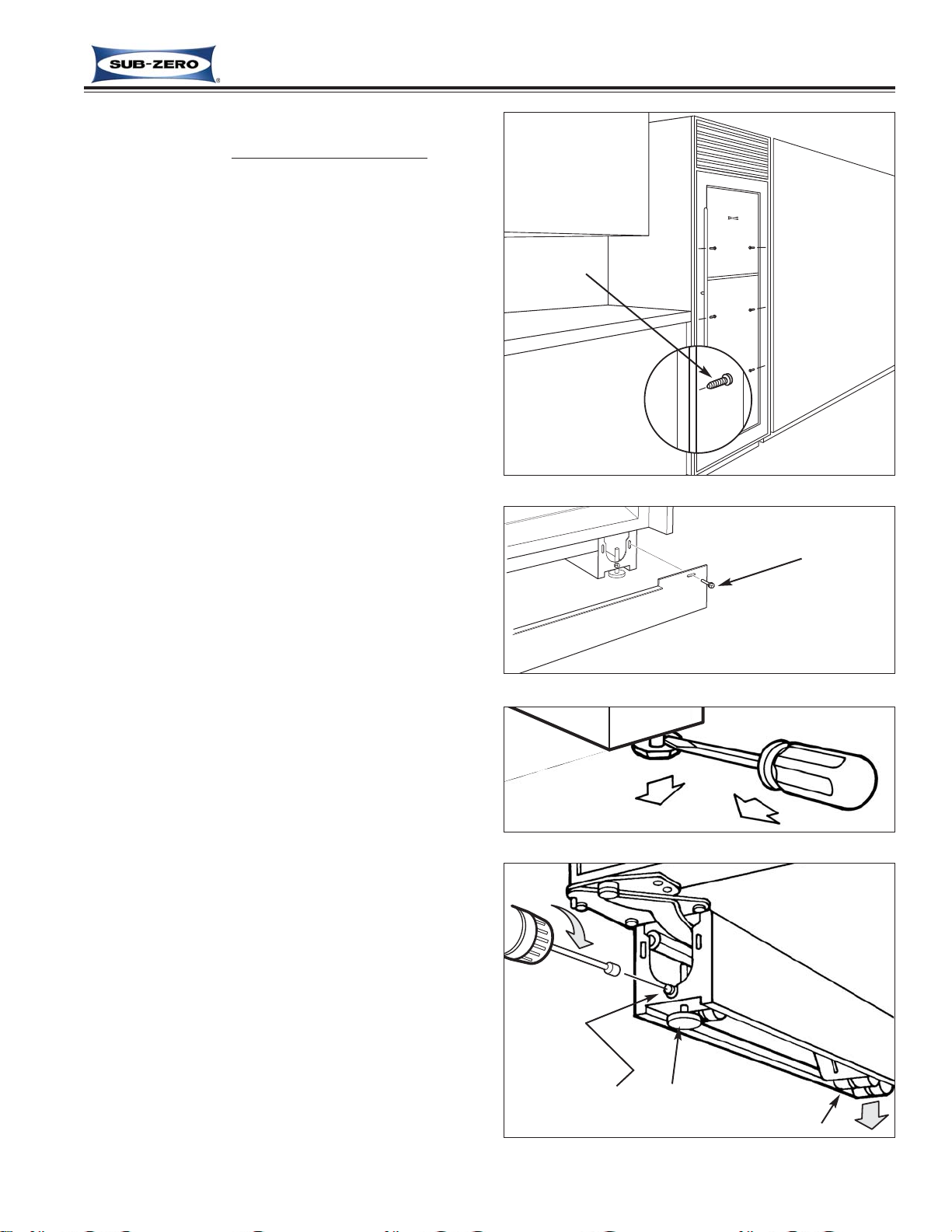
Unit Leveling (430-2)
NOTE: Unit must be installed before final leveling
. If
unit is anchored to cabinets, remove anchor screws
before leveling, reinstalled after (See Figure 2-10).
1. Remove kickplate (See Figure 2-11).
2. To raise front, turn front leveler legs counterclock-
wise, clockwise to lower (See Figure 2-12).
3. At front of unit base is an adjusting screw that reach-
es to rear leveler/roller assembly. To raise unit rear,
use 5/16” socket wrench to turn adjusting screw
clockwise to raise, counterclockwise to lower (See
Figure 2-13).
NOTE: Level is best checked at top & side mainframe.
Figure 2-12. Adjusting Front Leveling Legs
Figure 2-10. Anchoring Screws Removal
Screw
Rear Leveler
Adjusting Screw
Front Leveling Leg
Rear Leveler Assy
Page 11
Installation Information
Wine Storage
Wine Storage
(400-
(400-
2
2
)
)
Series
Series
2-6
#3758410 - Revision C - May, 2014
Figure 2-15. Door / Top Cabinet Hinge Adjustment
Figure 2-16. Door / Top Door Hinge Adjustment
Cabinet Hinge
Shipping Screws
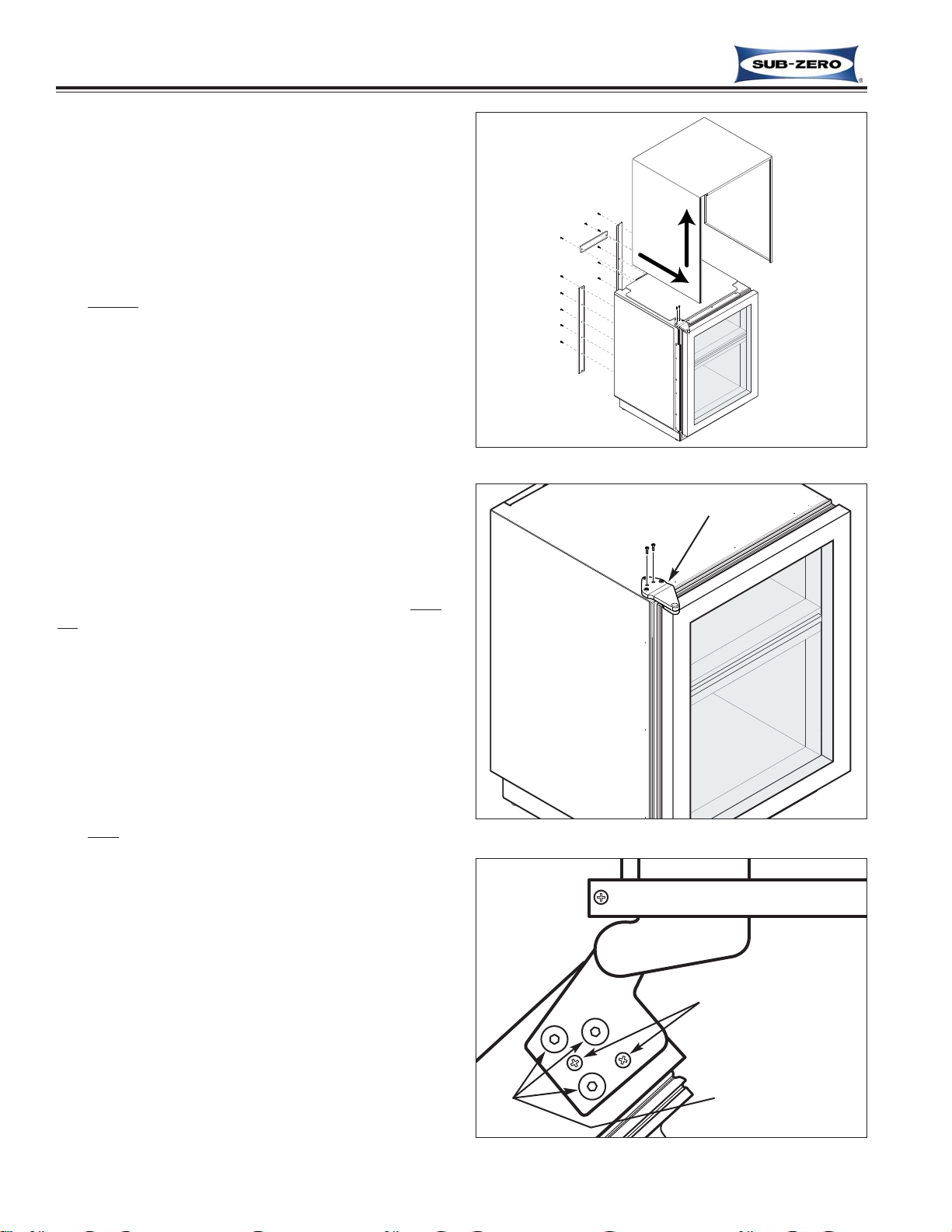
Door Adjustment (424-2, 424FS-2)
NOTE: Unit must be level before adjusting door.
NOTE: If 424FS-2 door needs adjusting, stainless steel
wrap must be removed to adjust top cabinet hinge (See
Figure 2-14).
If unit is properly installed, blocked and leveled, it may
still be necessary to adjust door left to right and/or in
and out. Adjustments are performed at top and/or bottom cabinet
hinge(s) (See Figure 2-15).
1. Working on only one hinge at a time (top or bottom),
remove and discard two small Phillips head shipping
screws from cabinet hinge before attempting adjustments.
2. Using a 1/8” Allen-wrench, loosen and “re-snug” cabinet hinge screws, allowing door adjustment.
3. Adjust door as required.
4. After adjusting door, tighten cabinet hinge screws
and check for proper door seal.
Door and/or Drawer Adjustment (427-2 & 427R-2)
NOTE: Door and/or drawers on models 427-2 & 427R2 are non-adjustable. Instead, door and/or drawer pan
els must be adjusted if there is alignment problems.
Refer to Installation Manual.
NOTE: Unit must be level before adjusting door and/or
drawer panels.
Door Adjustment (430-2)
If unit is properly installed, blocked and leveled, it may
still be necessary to adjust door left to right and/or in
and out. Adjustments are performed at top and/or bottom door
hinge(s) (See Figure 2-16).
1. Working on only one hinge at a time (top or bottom),
remove and discard two small Phillips head shipping
screws from door hinge before attempting adjustments.
2. Using a 1/8” Allen-wrench, loosen and “re-snug” door
hinge screws, allowing door adjustment.
3. Adjust door as required.
4. After adjusting door, tighten door hinge screws and
check for proper door seal.
Remove shipping
screws.
Loosen and re-snug
cabinet hinge
screws.
Top
Door Hinge
Door Hinge Screws
Figure 2-14. Wrap Removal
1. Remove
back brackets.
2. Slide
wrap
forward
& lift up
Page 12

Wine Storage
Wine Storage
(400-
(400-
2
2
)
)
Series
Series
Installation Information
2-7
#3758410 - Revision C - May, 2014
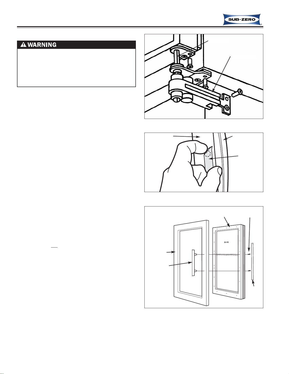
Door Stop Adjustment (427-2 & 427R-2)
Models 427-2 and 427R-2 have a 90° door stop cam
built into the hinge system. The 90° door stop cam is
located in the center portion of the hinge.
To adjust the stop, use a standard straight-blade screwdriver to rotate cam until stop point is reached. (See
Figure 2-17)
NOTE: Door stop adjustment must be performed at
both bottom and top hinges.
Door Stop Installation (430-2)
For the model 430, optional 90° and 105° door stops
are available, free of charge from Parts Distributors
and/or Product Distributors. The part number for the
90° stop is #DS90, and the part number for the 105°
stop is #DS105.
To install a door stop, the door must be closed, then
(See Figure 2-18):
1. Slide door stop cam up onto bottom hinge pin.
2. Position stub on door stop into hole in cabinet
hinge.
3. Retain door stop by pushing E-Ring into groove at
end of bottom hinge pin, making sure E-ring is
clipped securely into groove.
Figure 2-17. Door Stop Adjustment
Figure 2-18. Door Stop Installation
E-Ring
Door Stop
Hinge Pin
90° Stop Cam
Page 13
Installation Information
Wine Storage
Wine Storage
(400-
(400-
2
2
)
)
Series
Series
2-8
#3758410 - Revision C - May, 2014
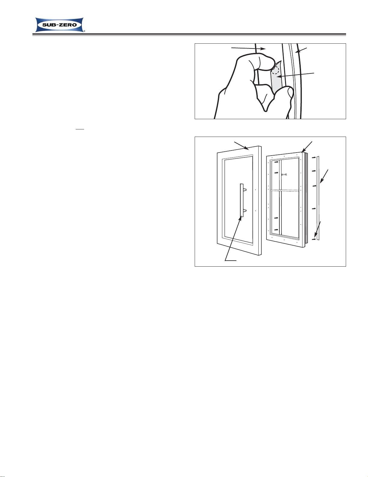
Figure 2-20. Poly Tape Removal
Figure 2-21. Stainless Steel Door Panel Removal
Poly Tape
Door Gasket
Door Frame
Handle
Screws
SS Handle
(Door Hinges &
Screws - not shown)
SS Panel
Poly
Tape
Door Assy
METAL DOOR PANELS MAY HAVE SHARP EDGES.
PROTECTIVE GLOVES SHOULD BE WORN WHEN
HANDLING PANELS.
DOOR PANELS MAY BE HEAVY OR UNSTABLE. IF
THEY WERE TO FALL, THEY COULD CAUSE SERIOUS PERSONAL INJURY.
Door Panel Removal and Installation (All Models)
Figure 2-19. Door Closer Removal
Door Closer
Hinge Pin
Classic, carBon and Platinum Stainless Steel Door
Panel Removal and Installation (424-2)
To remove a 424-2 SS door panel, the door must first
be removed from the unit.
To Remove the Door:
1. Remove mounting screws securing door closer to
the unit base (See Figure 2-19)
2. Slide door closer down off of bottom door hinge pin
NOTE: It may be necessary to lean unit back
slightly to create enough clearance between hinge
pin and floor.
3. Open door and extract screws from top door hinge.
4. Lean door away from unit slightly and lift door out of
bottom cabinet hinge.
To Remove a Stainless Steel Panel:
1. Lay door down and remove bottom door hinge and
switch depressor. (If lock and/or screws are present on bottom handle side, remove them also.)
2. Remove Poly-tape under gasket on handle side
which covers handle mounting screw holes (See
Figure 2-20).
NOTE: Do not
discard tape. It must be reapplied
when panel is reinstalled.
3. Extract handle mounting screws and pull handle
from front of door (See Figure 2-21).
4. Lift stainless steel panel from door.
NOTE: To install stainless steel panel, reverse steps
above.
Page 14
Wine Storage
Wine Storage
(400-
(400-
2
2
)
)
Series
Series
Installation Information
2-9
#3758410 - Revision C - May, 2014
Figure 2-23. Overlay Door Panel Removal
Door Assy
Poly
Tape
Panel
Mounting
Screws
Overlay Panel
SS Handle Shown (Handle may vary)
Figure 2-22. Poly Tape Removal
Poly Tape
Door Gasket
Door Frame
Overlay Door Panel Removal and Installation (424-2)
Overlay panels are attached to the door using screws
passing through the door frame from the rear, into the
panel. The handle may also be attached through the
door frame or just through the panel.
To Remove an Overlay Panel:
1. Open door.
2. Remove Poly-tape under gasket which covers
panel mounting screw holes (See Figure 2-22).
NOTE: Do not
discard tape. It must be reapplied
when panel is reinstalled.
3. Extract panel mounting screws, and possibly handle
mounting screws. (See Figure 2-23)
4. Pull overlay panel from door.
NOTE: To install overlay panel, reverse steps above.
Page 15

Installation Information
Wine Storage
Wine Storage
(400-
(400-
2
2
)
)
Series
Series
2-10
#3758410 - Revision C - May, 2014
Figure 2-25. Door Panel Removal
Figure 2-26. Drawer Panel Removal
Drawer Panel
Mounting Bracket
- Upper
Drawer Panel
Mounting
Bracket
- Bottom
Door Panel Removal and Installation
(427-2 & 427R-2)
Models 427-2 and 427R-2 are NOT supplied with panels from the factory. Panels are purchased separately.
Door panels are attached with screws passing from the
rear through the door frame into the panel. The handle
is attached to the panel.
To remove a door panel:
1. Open door.
2. Remove Poly-tape under gasket which covers
panel mounting screw holes (See Figure 2-24).
NOTE: Do not
discard tape. It must be reapplied
when panel is reinstalled.
3. Extract panel mounting screws. (See Figure 2-25)
4. Pull panel from door.
NOTE: To install panel, reverse steps above.
Drawer Panel Removal and Installation (427R-2)
NOTE: Model 427R-2 is NOT supplied with panels
from the factory. Panels are purchased separately.
Drawer panels are attached using screws passing
through mounting brackets at the bottom of each drawer, and a dog-eared bracket on the back of the panel fitting into slots in the face of the drawers. Handles are
attached to the panels.
To remove a drawer panel (See Figure 2-26):
1. Open drawer.
2. Extract the six screws at bottom drawer panel
bracket.
3. Pull bottom of drawer panel out slightly while pulling
downward.
NOTE: To install panel, reverse steps above.
Figure 2-24. Poly Tape Removal
Poly Tape
Door Gasket
Door Frame
Page 16
Wine Storage
Wine Storage
(400-
(400-
2
2
)
)
Series
Series
Installation Information
2-11
#3758410 - Revision C - May, 2014
Figure 2-29. Stainless Steel Door Panel Removal
Panel
Door Assy
Handle
Screw
(Door Hinges &
Screws - not shown)
Handle
Door closer is spring loaded and may recoil quickly
when detached.
Hinge-Side
Panel Mounting Screw
Handle Stand-off
Panel
Spacer/
Washer
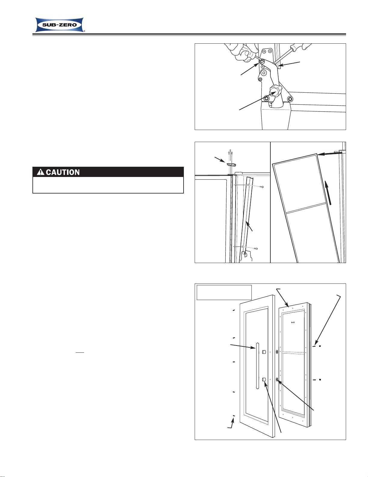
Classic, carBon and Platinum Stainless Steel Door
Panel Removal and Installation (430-2)
To remove a 430-2 SS door panel, the door must first
be removed from the unit.
To Remove the Door:
1. Open door until hole in bottom cabinet hinge aligns
with hole in door closer arm (See Figure 2-27).
2. Insert short screwdriver up into the two holes.
NOTE: This screwdriver will be used to pry the
door closer arm back onto the door hinge stud.
3. Use a small straight-blade screwdriver to remove E-
ring which holds door closer arm to bottom door
hinge stud.
4. Pry door closer arm down off of door hinge stud.
Figure 2-27. Door Closer Disconnect
Remove
E-Ring
Pry down
Screwdriver
up into holes
Figure 7-28a.
Trim/Hinge Removal
Lean door
away from
unit and
lift up
Door
Trim
Door
Hinge
Figure 7-28b.
Door Removal
5. Remove hinge-side door trim (See Figure 7-28a).
6. With a 1/8” Allen-wrench and Phillips screwdriver,
extract all screws from top door hinge.
7. Lean door away from unit and lift off of bottom cabi-
net hinge (See Figure 7-28b).
NOTE: When reinstalling door, use screwdriver in
cabinet hinge hole and door closer arm hole to pry
door closer arm back onto the door hinge stud.
To Remove a Stainless Steel Panel:
1. Lay door down and remove bottom door hinge and
switch depressor at top of door. (If lock and/or
screws are present on top handle side, remove
them also.)
2. Remove panel mounting screws from hinge side of
door.
3. Remove Poly-tape under gasket on handle side
which covers handle mounting screw holes (See
Figure 2-29).
NOTE: Do not
discard tape. It must be reapplied
when panel is reinstalled.
4. Extract handle mounting screws and pull handle
from front of door.
5. Lift stainless steel panel from hinge side first, pivot-
ing it off of handle side of door.
NOTE: To install stainless steel panel, reverse steps
above.
Page 17
Installation Information
Wine Storage
Wine Storage
(400-
(400-
2
2
)
)
Series
Series
2-12
#3758410 - Revision C - May, 2014
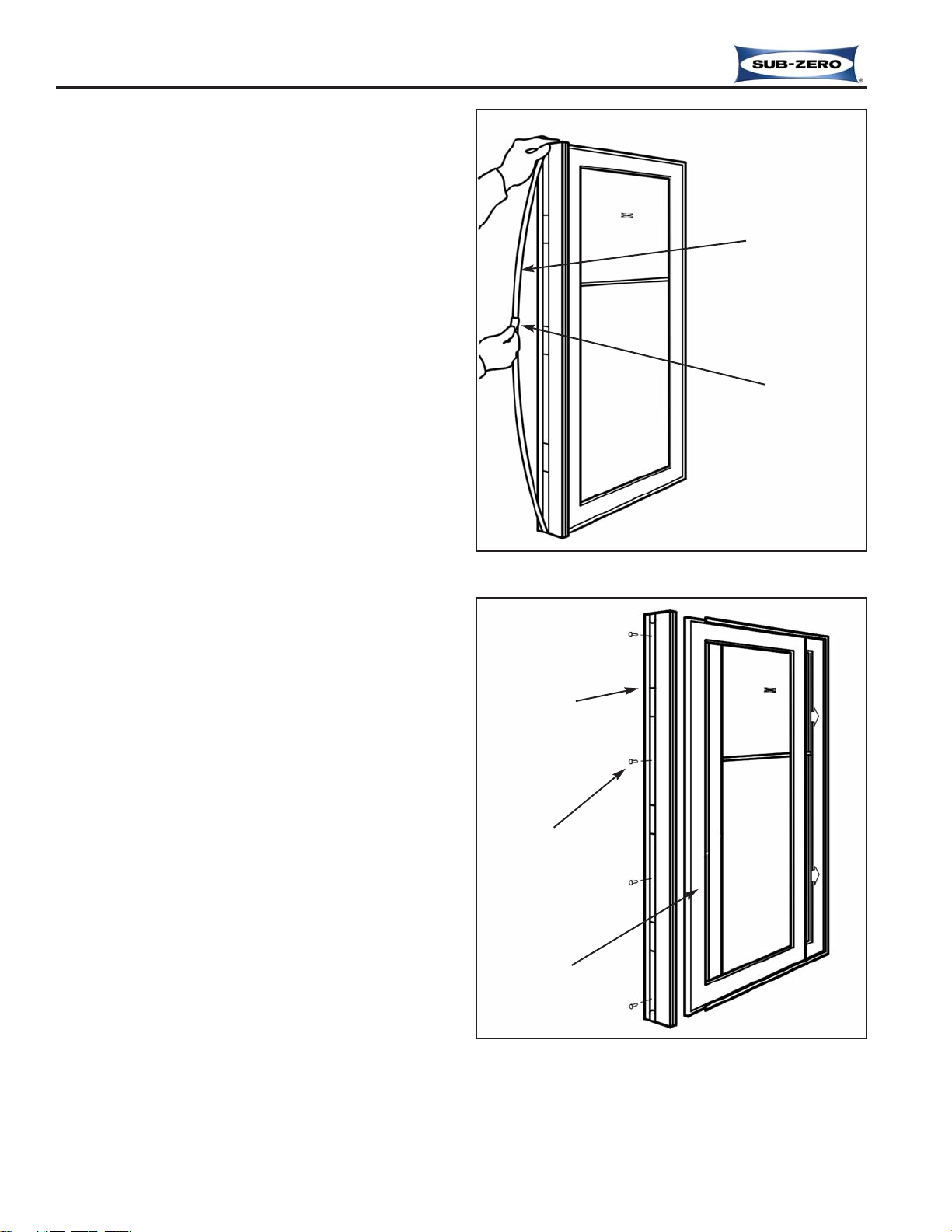
Figure 2-30. Trim Molding Removal
Figure 2-31. Framed and Overlay Handle / Handle
Side Trim & Door Panel Removal
Framed & Overlay Door Panel Removal / Installation
(430-2)
Framed and overlay panels are attached to the door by
sliding 1/4” (6 mm) thick edge of panel under door trim.
On the handle side, there may also be additional
screws passing through the door frame from rear into
the panel for increased support. Overlay handles may
also be attached through the door frame, or just through
the panel.
To remove a framed or overlay panel, the handle, or
trim on handle side must first be removed. Handles
and/or handle-side trim is secured to the door with
screws. The screw heads are then concealed by a
magnetic trim strip.
To Remove Handle or Handle-side Trim (See Figure
7-30 & 7-31):
1. Press a sticky piece of tape to center of magnetic
trim strip.
2. Pull tape so that trim strip bows away from door,
disengaging both ends of trim strip from the endcaps.
3. With mounting screws exposed, extract the screws,
then pull handle (or handle-side trim) from door.
To Remove Panel (See Figure 7-31):
1. Slide panel towards handle side, and out from
under door trim.
NOTE: If the panel will not slide from under door
trim, panel mounting screws and/or handle mounting screws may have been used.
a. Open door and remove Poly-tape from under
gasket.
b. Extract panel mounting screws, and/or handle
mounting screws.
c. Slide panel towards handle side, and out from
under door trim.
Magnetic
Trim Molding
Handle or
Handle-side
Trim
Screws
Piece of
Tape
Framed or
Overlay Panel
Page 18
Electronic Control System
Wine Storage
Wine Storage
(400-
(400-
2
2
)
)
Series
Series
3-2
#3758410 - Revision C - May, 2014
Term/Component Definition / Description
Control Board …………………………..The printed-circuit board (PC Board) containing the microprocessor, relays
and electrical connections for monitoring and controlling functions and operations of the unit.
Microprocessor ……………………...... An electrical component on the control board which receives electrical signals
from other components, processes that information, then sends an electrical
signal to the relays on the board to open or close, and other electronic components in the unit to switch on or off.
Relay …………………………………… Electrical components on the control board which switch other components in
the unit ON and OFF when instructed to do so by the microprocessor.
LED (Light Emitting Diode) ………...... A small electronic “tube” that lights-up when power is supplied to it. In the
control panel assembly, LED’s are arranged to show values (numbers).
LED’s are also used as back-lighting for the indicators in the control panel.
Control Panel Assembly ………………The information input and read-out area of the electronic control system,
located between the two wine storage compartments. NOTE: The model
427R-2 also has a control panel assembly at top front of the top refrigerator
drawer assembly.
Membrane Switch …………...……….. An integral part of the control panel assembly, which consists of the function
keys used for all input functions to the electronic control system.
Keys (Function Keys) ………………… The buttons on the Membrane switch used for input functions. (The keys are:
UNIT ON/OFF, LIGHTS ON/OFF, ALARM ON/OFF, COLDER, WARMER)
Indicators ………………….....………... The words and numbers that are displayed at the control panel. (Example:
Temperature displays, temperature alarm bell, “SERVICE”, and error codes.)
Set-Point ……………………………….. The desired compartment temperature, established by pressing the COLDER
or WARMER keys.
High Offset (Cut-in)………………….....During normal operation of a wine storage unit, it is the maximum evaporator
temperature the electronic control system will allow before calling for cooling.
Low Offset (Cut-out)…………………... During normal operation of a wine storage unit, it is the minimum compart-
ment air temperature the electronic control system will allow before interrupt-
ing cooling.
Offset Temperature Range …………... The difference between the low offset and the high offset.
Thermistor (Temperature Sensor) ….. A resistor with which resistance changes as temperatures around it change.
For electronic control system purposes, the microprocessor measures this
resistance and displays it as a temperature reading at the control panel.
Display Units of Measure……………...Temperatures displayed at the control panel may be in fahrenheit (°F), or cel-
sius (°C), units of measure. Switching from one to the other display units of
measure is accomplished through a series of key strokes.
Error Codes .…………………………... The code numbers accompanied by the letters “EC” that appear in the control
panel display windows during diagnostic mode if the unit experienced specific
problems related to electrical signals supplied by electrical components.
Electrical “Pulse”.................................. A non-constant supply of voltage, or electrical signal, the duration of which is
often measured in milliseconds.
Electrical Polarity..................................The positive ( + ) and negative ( - ) sides of the alternating current sinewave.
WINE STORAGE ELECTRONIC CONTROL TERMINOLOGY & COMPONENT DESCRIPTIONS
The electronic control system monitors, regulates and controls a variety of functions; it also displays temperatures,
possible problems with the appliance and the temperature alarm bell status.
The table below defines some basic electronic control terminology. An understanding of this information is needed
in order to comprehend the operations and functions of the electronic control system.
Page 19

Wine Storage
Wine Storage
(400-
(400-
2
2
)
)
Series
Series
Electronic Control System
3-3
#3758410 - Revision C - May, 2014
BASIC WINE STORAGE ELECTRONIC CONTROL SYSTEM
This page contains a basic illustration of the 400-2 Series electronic control system (See Figure 3-1). Input operations are performed at the membrane switch (part of the control panel assembly), with monitoring, regulating and
controlling functions taking place at the control board (located directly behind the control panel). Temperatures and
possible problems with the unit are displayed at the control panel display. The entire electronic control system is
described in greater detail on the following pages.
NOTE: The diagram below is not an exact electrical representation of the electronic control system. For more
detailed electrical diagrams refer to the wiring diagram and schematic supplied with the unit.
Figure 3-1. Basic Wine Storage (400-2) Series Electronic Control System
WINE STORAGE
ON/OFF
N.C.
COLDER WARMER COLDER WARMER
BELL ON
SERVICE
LIGHTS
UNIT
ON/OFF
ON/OFF
N.O.
N.O.
Page 20

Electronic Control System
Wine Storage
Wine Storage
(400-
(400-
2
2
)
)
Series
Series
3-4
#3758410 - Revision C - May, 2014
Figure 3-2. Control Board Layout
Figure 3-3. Control Board Summary Table
WINE STORAGE CONTROL BOARD
LAYOUT AND SUMMARY TABLE
The electrical connection points on the wine storage control board
are labeled Alphanumerically. These labels correspond with the
alphanumeric control board summary layout table on the wiring diagram. By referencing the table, it is possible to identify which components are connected at which connection points on the control
board. Below is a layout diagram of the control board, followed by a
copy of a summary table. (See Figures 3-2 and 3-3)
NOTE: All components on the control board are non-replaceable. If
problems with the control board are identified, the complete control
board must be replaced.
DESCRIPTIONCIRCUIT FUNCTION COLOR
TAN
WHT/RED
WHT/BLUE
GRAY/WHT
CONTROL REF
FOR HOME ALARMS
EMPTYP2
ALARM CIRCUIT-COMMON FOR HOME ALARMS
ALARM CIRCUIT-NORMALLY CLOSEDP4 FOR HOME ALARMS
ALARM CIRCUIT-NORMALLY OPEN
BLUE/WHITELOWER CABINETP2 SENSES TEMPERATURE
BLUE/BLACKUPPER CABINETP3 SENSES TEMPERATURE
BLUE/REDLOWER EVAPORATORP5 SENSES TEMPERATURE
BLUE/BLACKUPPER CABINETP4 SENSES TEMPERATURE
ORANGE/REDLOWER EVAPORATORP6 SENSES TEMPERATURE
BLUE/YELLOWUPPER EVAPORATORP7 SENSES TEMPERATURE
ORANGE/YELLUPPER EVAPORATORP8 SENSES TEMPERATURE
J1
J8
1
J2
8
1
2
WINE
CONTROL
J3
BOARD
14
E2
E1
E3
J3
P5
P3
LOW VOLTAGE CIRCUITS
GRAY
BLACK
POWER INTO BOARD
POWERS COMPRESSOR
J2 THERMISTER CIRCUITS
P1 REFRIGERANT VALVE
P1 LOWER CABINET SENSES TEMPERATURE BLUE/WHITE
WHITE
COOLS LOWER COMPARTMENT
NEUTRAL INTO BOARD
POWER IN
EMPTY
COMPRESSOR
NEUTRAL
LOWER EVAP. FAN
EMPTYP7
UPPER EVAP. FAN COOLS UPPER COMPARTMENT
LIGHTS OVERRIDEP9 ORANGEON WHEN LIGHTS ON 100%
EMPTY
400 SERIES CONTROL BOARD SUMMARY/ LAYOUT
P12
P8 BLUE
P11
P10 PINK
P6 EMPTY
J3
E2
E3 LIGHTS POWERS LIGHTS BROWN
P13
P14 GROUND EARTH GROUND GREEN/YELLOW
E1
CIRCUIT DESCRIPTION FUNCTION COLOR
120 VOLT CIRCUITS
Page 21

Wine Storage
Wine Storage
(400-
(400-
2
2
)
)
Series
Series
Electronic Control System
3-5
#3758410 - Revision C - May, 2014
WINE STORAGE CONTROL PANEL LAYOUT
Figure 3-4. Wine Storage Control Panel Layout
WHEN IN OFF MODE, 115 VOLTS AC IS STILL PRESENT AT CONTROL BOARD.
Figure 3-5. Unit ON/OFF, Press UNIT ON/OFF Key
BASIC WINE STORAGE INPUT OPERATIONS
The following pages describe basic input operations performed at the control panel. The subjects covered are:
switching unit ON / OFF; adjusting set-point (temperature adjustment); switching lighting system ON / OFF, and
enabling and disabling temperature alarm feature. Please note that though possible to display temperatures in
Fahrenheit or Celsius, in most cases Fahrenheit readings are shown.
Unit ON/OFF
400-2 Series units are shipped in the Off Mode. By pressing and releasing the UNIT ON/OFF key, power is allowed
past the control board to the rest of the unit (See Figure 3-5).
BELL ON
&
SERVICE
indicators
Upper
Compartment
Temp Reading
Lower
Compartment
Temp Reading
Upper Compartment
COLDER
key
WARMER
key
Lower Compartment
COLDER
key
WARMER
key
Alarm Bell
ON/OFF key
UNIT
ON/OFF
key
LIGHTS
ON/OFF
key
Page 22

Electronic Control System
Wine Storage
Wine Storage
(400-
(400-
2
2
)
)
Series
Series
3-6
#3758410 - Revision C - May, 2014
Adjusting Set-Points (Temperature Adjustments)
To adjust set-points, press WARMER or COLDER key on control panel in multiple key strokes
until desired set-point
is achieved (See Figure 3-6). One key stroke equals one degree (1°) change.
NOTE: To check set point, press either the WARMER or COLDER key, keeping in mind that the initial key stroke
will change the previous set-point by a one degree increment or decrement depending on key stroke choice.
NOTE: The set-point will be displayed for ten (10) seconds after the last key stroke. After the 10 second delay, the
compartment temperature will be displayed. As the compartment temperature changes, the temperature displayed
on the LCD will change by no more than one degree per minute.
NOTE: The temperature range in a wine storage compartment is 38°F / 3°C to 65°F / 18°C.
Figure 3-6. Adjust Set-Point, Press COLDER or WARMER Keys
Lighting System ON/OFF
For the purpose of displaying a wine supply, it is possible to energize the lights 100% of the time, even if the door is
closed. To do so, press and release the LIGHTS ON/OFF key (See Figures 3-7). To disable this feature, press and
release the LIGHTS ON/OFF key again.
Alarm “BELL” ON/OFF (Temperature Alarm)
There is an audio/visual temperature alarm that can be enabled to warn a customer if excessive warm or cold temperatures are experienced. To enable the alarm, press and release the key with the bell on it (See Figure 3-8). If
the alarm is enabled, the BELL ON indicator will illuminate. To disable this feature, press and release the key with
the bell on it again, and the BELL ON indicator will de-energize.
NOTE: If the alarm is enabled and there is a temperature problem, the BELL ON indicator will flash and the alarm
will beep. The alarm feature can also be tied in with a home security alarm system.
Figure 3-7. Light System ON/OFF, Press LIGHTS ON/OFF Key
Figure 3-8. Alarm Bell ON/OFF, Press
Adjusting lower compartment set-point “colder”
(Alarm Bell) Key
Page 23

Wine Storage
Wine Storage
(400-
(400-
2
2
)
)
Series
Series
Electronic Control System
3-7
#3758410 - Revision C - May, 2014
UNIQUE WINE STORAGE INPUT OPERATIONS
The following pages illustrate unique input operations performed at the control panel, namely: Temperature Units
Selection Mode, Sabbath Mode and Showroom Mode.
Temperature Units Selection Mode (Selecting Degrees Fahrenheit or Degrees Celsius Display)
The electronic control is initially set to display temperature in Fahrenheit (°F) units of measure. Units of measure
can be converted from °F to °C (Celsius), and/or back again. This operation is called Temperature Units Selection.
NOTE: Temperature Units Selection must be performed within the first minute after switching the unit ON.
To convert temperature units of measure from Fahrenheit (°F) to Celsius (°C) readings, press and hold the alarm bell
key and the UNIT ON/OFF key simultaneously for five (5) seconds, then release the keys (See Figure 3-9). A temperature is now shown in the left display window, and the right display window indicates the units of measure as °F
or °C. In this case, a temperature will be displayed in Celsius (°C) units of measure. (See Figure 3-10)
To switch from Celsius to Fahrenheit, repeat the steps above within 1 minute of switching the unit on.
NOTE: Temperature Units Selection Mode will end ten (10) seconds after the last key stroke.
NOTE: Do not
press and hold the UNIT ON/OFF key first, that will simply switch the unit OFF.
Figure 3-9. Initiating Temperature Units Selection Mode:
Press and Hold Alarm Bell Key and Unit ON/OFF Key Simultaneously for Five (5) Seconds
Figure 3-10. Temperature Units Selection Mode Initiated, Celsius Units (°C) Displayed
Page 24

Electronic Control System
Wine Storage
Wine Storage
(400-
(400-
2
2
)
)
Series
Series
3-8
#3758410 - Revision C - May, 2014
Sabbath Mode (Lights Off Mode)
Sabbath Mode was incorporated into the electronic control system for the observance of certain religious days.
Initiating Sabbath Mode disables the LEDs and lighting system.
To initiate Sabbath Mode, the unit must first be switched OFF using the UNIT ON/OFF key (See Figure 3-11), then
press and hold the UNIT ON/OFF key for ten (10) seconds, until the LEDs and lights switch OFF (See Figure 3-12).
To return to normal operation, press and release the UNIT ON/OFF key.
NOTE: During Sabbath Mode, the evaporator fans may function when the door is open.
NOTE: During Sabbath Mode, the LEDs are disabled and set-points cannot be changed.
Figure 3-11. Switch Unit OFF First
Figure 3-12. Initiate Sabbath Mode, Press and Hold UNIT ON/OFF Key for 10 Seconds
Hold for 10 Seconds
Showroom Mode
Showroom Mode was incorporated into the electronic control system so the appliance could be displayed in a showroom setting. When in Showroom Mode, all cooling functions are disabled, but the lighting system remains active.
To initiate Showroom Mode, the unit must first be switched OFF using the UNIT ON/OFF key (See Figure 3-13).
Then press and hold the upper compartment WARMER and COLDER keys, and the UNIT ON/OFF key, then
release all three keys (See Figure 3-14). The unit is now in Showroom Mode. This can be verified by checked for
evaporator fan operation, and/or compressor operation. To return the unit to normal operation, repeat the steps
above.
NOTE: Always check set-points after returning unit to normal operation.
Figure 3-13. Switch Unit OFF First
Figure 3-14. Initiate Showroom Mode,
Press Upper
COLDER and WARMER Keys and UNIT ON/OFF Key, then Release
Page 25

Wine Storage
Wine Storage
(400-
(400-
2
2
)
)
Series
Series
Electronic Control System
3-9
#3758410 - Revision C - May, 2014
FUNCTION OF THE WINE STORAGE ELECTRONIC CONTROL SYSTEM
The following pages explain monitoring, regulating and controlling functions of the electronic control system. In most
cases signal traces for the 424-2 wiring schematic are used to show current flow for functions being explained.
TO AVOID ELECTRIC SHOCK, POWER TO THE UNIT MUST BE DISCONNECTED WHENEVER ACCESSING
AND/OR REMOVING COMPONENTS POWERED BY ELECTRICITY OR COMPONENTS NEAR OTHER ELECTRICAL COMPONENTS.
EVEN WHEN UNIT IS SWITCHED OFF, AC POWER IS STILL PRESENT AT THE CONTROL BOARD.
Supply Power to the Lighting System
When the unit is plugged in, a continuous 115 Volts AC is supplied to the lighting system, making it possible to energize the lights 100% of the time, even if the door is closed. (See Lighting System ON/OFF). The lighting system
can also be disabled for observance of certain religious days, (See Sabbath Mode). The illustration below shows
normal operation, with 115 Volts AC supplied to the unit. (See Figure 3-15)
ELECTRIC SHOCK HAZARD. 115 VOLTS AC IS STILL PRESENT AT THE CONTROL BOARD AND LIGHT
SWITCH WHEN LIGHTS ARE DISABLED.
Figure 3-15. Lighting System Signal Trace (Normal Operation)
NOTE: If display lighting is activated, power is sup-
plied to lights, bypassing light switch
GREEN/YELLOW
NEUT
GRAY
WHITE
LIGHTS
LIGHTS
UPPER
M
EVAPORATOR FAN MOTORS
LOWER
M
AWECO REF VALVE
680 Ω
BROWN
N.C.
ORANGE
PINK
N.O.
BLUE BLUE
N.O.
TAN
ORANGE
PINK
CONDENSER FAN MOTOR
M
STARTING RELAY
OVERLOAD PROTECTOR
WHITE
COMPRESSOR
M
COMPRESSOR
J8
WINE
CONTROL
BOARD
BLACK
L1
115 VOLTS
60 CYCLES
J1
1
J2
8
1
2
J3
14
BLUE
PINK
E2
E1
E3
Page 26

Electronic Control System
Wine Storage
Wine Storage
(400-
(400-
2
2
)
)
Series
Series
3-10
#3758410 - Revision C - May, 2014
Display Average Compartment Temperatures
The temperature signal from the thermistor in each compartment is monitored by the microprocessor, then displayed
in the control panel display. The LED arrow closest to the appropriate display window indicates which compartment
(upper or lower) the temperature is associated with. Though compartment air
temperature fluctuates slightly, the
“average” temperature is displayed (See Figure 3-16).
NOTE: The temperature range in a wine storage compartment is 38°F / 3°C to 65°F / 18°C.
NOTE: If a compartment temperature should ever exceed either the high offset or low offset (for example: when a
door is left open), the temperature displayed at the control panel will change by 1° per minute.
Figure 3-16. Temperature Display (Shown in Fahrenheit Units of Measure)
Upper
Compartment
Temp Reading
Lower
Compartment
Temp Reading
Lower Compartment Arrow
Upper Compartment Arrow
Page 27

Control Compressor, Condenser Fan, Dual Refrigerant Valve and Evaporator Fan Motors
The control senses evaporator and compartment temperatures via thermistors; one on each evaporator, and one in
each compartment. High Offset (Cut-in) is governed by the evaporator temperatures. Low Offset (Cut-out) is governed by the compartment temperatures. High Offset and Low Offset are based on the set-point.
If either evaporator calls for cooling (evaporator temperature at high offset), power is supplied to the compressor and
condenser fan motor, cycling them ON. The corresponding evaporator fan relay supplies power to the appropriate
evaporator fan switch, cycling the fan on. Then, two relays on the control board are used to control the dual refrigerant valve. The relays are in series with one another. The first “pulse” relay controls the length of time the solenoid
is energized (500ms / 30 pulses per 1/2 second). The second “sign” relay controls the negative polarity, or positive
polarity of the pulse supplied to the valve’s solenoid (determined by which evaporator is calling for cooling, ( + ) =
Upper Evaporator, ( - ) = Lower Evaporator). So, when an evaporator calls for cooling, the bead inside of the T-connection of the refrigerant valve is forced to one side or the other, depending on the polarity of the pulse, supplying
refrigerant to the appropriate evaporator (See Figure 3-17).
NOTE: If neither compartment is calling for cooling, the compressor and condenser fan are switched off.
NOTE: Evaporator fans are switched off when the door is open and disabled if the unit is in Showroom Mode.
NOTE: When in Sabbath Mode, evaporator thermistors still control energizing of the compressor and evaporator
fans, except
there is a random fifteen
(15) to twentyfive (25) second delay
before power
is supplied to
components.
Wine Storage
Wine Storage
(400-
(400-
2
2
)
)
Series
Series
Electronic Control System
3-11
#3758410 - Revision C - May, 2014
Figure 3-17. Cooling Signal Trace (Upper Evaporator at High-Offset Temperature, Calling for Cooling)
1. Temperature at
high offset,
Calling for
cooling
2. Temperature
above low
offset
5. 115VAC pulse,
(+ polarity)
supplied to
solenoid,
valve opens
supplying
refrigerant to
upper evaporator
3. Energized
4. Energized
J8
WINE
CONTROL
BOARD
BLACK
L1
J1
1
J2
8
1
2
J3
14
E2
E1
E3
MEMBRANE SWITCH
115 VOLTS
60 CYCLES
BLUE
PINK
LOW VOLTAGE
GREEN/YELLOW
NEUT
GRAY
WHITE
N.C.
BROWN
PINK
BLUE BLUE
ORANGE
N.O.
N.O.
TAN
OVERLOAD PROTECTOR
WHITE
ORANGE
PINK
LIGHTS
LIGHTS
UPPER
M
EVAPORATOR FAN MOTORS
LOWER
M
AWECO REF VALVE
680 Ω
CONDENSER FAN MOTOR
M
COMPRESSOR
M
COMPRESSOR
STARTING RELAY
THERMISTER 1
LOWER CABINET
THERMISTER 2
UPPER CABINET
DISPLAY
J8
WINE
CONTROL
BOARD
THERMISTER 3
J1
1
J2
8
1
2
J3
BLUE W/WHITE
BLUE W/WHITE
BLUE W/BLACK
BLUE W/BLACK
BLUE W/RED
ORANGE W/RED
BLUE W/YELLOW
ORANGE W/YELLOW
WHITE W/RED
WHITE W/BLUE
GRAY W/WHITE
LOWER EVAPORATOR
THERMISTER 4
UPPER EVAPORATOR
14
E2
E1
E3
Page 28

Electronic Control System
Wine Storage
Wine Storage
(400-
(400-
2
2
)
)
Series
Series
3-12
#3758410 - Revision C - May, 2014
Monitor and Control Off-cycle Defrost
Since High Offset (Cut-in) is governed by the evaporator temperature, the refrigeration system cannot be energized
until evaporator temperatures exceed 39°F / 4°C, with a 38°F/3°C set-point, and/or exceed 66°F / 19°C, with a
65°F/18°C set-point.
Figure 3-18. Off-cycle Defrost Signal Trace
No cooling called for
Refrigeration system not energized;
evaporators defrost
DISPLAY
J8
WINE
CONTROL
BOARD
BLACK
J1
1
J2
8
1
2
J3
14
E2
E1
E3
MEMBRANE SWITCH
L1
115 VOLTS
60 CYCLES
BLUE
PINK
NEUT
GREEN/YELLOW
GRAY
LOW VOLTAGE
J1
1
J8
WINE
CONTROL
BOARD
J2
8
1
2
J3
14
E2
E1
E3
WHITE
N.C.
BROWN
PINK
BLUE BLUE
ORANGE
N.O.
N.O.
TAN
ORANGE
PINK
LIGHTS
LIGHTS
UPPER
M
EVAPORATOR FAN MOTORS
LOWER
M
AWECO REF VALVE
680 Ω
CONDENSER FAN MOTOR
M
OVERLOAD PROTECTOR
WHITE
BLUE W/WHITE
BLUE W/WHITE
BLUE W/BLACK
BLUE W/BLACK
BLUE W/RED
ORANGE W/RED
BLUE W/YELLOW
ORANGE W/YELLOW
WHITE W/RED
WHITE W/BLUE
GRAY W/WHITE
COMPRESSOR
M
COMPRESSOR
STARTING RELAY
THERMISTER 1
LOWER CABINET
THERMISTER 2
UPPER CABINET
THERMISTER 3
LOWER EVAPORATOR
THERMISTER 4
UPPER EVAPORATOR
Page 29

Wine Storage
Wine Storage
(400-
(400-
2
2
)
)
Series
Series
Electronic Control System
3-13
#3758410 - Revision C - May, 2014
POSSIBLE WINE STORAGE ERROR INDICATORS
All wine storage units are equipped with an audio-visual temperature alarm feature, as well as low voltage wiring
provisions to allow the alarm to be tied into a home security alarm system. This section explains the temperature
alarm feature and the audio and/or visual error indicators that may alert a customer of a malfunction.
NOTE: If the temperature alarm feature is tied into a home security system, the connections are made using the
security system’s logic. If problems occur between the wine storage unit and the security system, then a home
security system technician should be contacted.
Warm Temperature Alarm
A warm temperature alarm can occur if either wine storage compartment remains warm for too long, causing several
consecutive maximum run-time cycles. During a warm temperature alarm, warm temperature readings may be displayed at the control panel, the SERVICE indicator will flash (See Figure 3-19). A warm temperature alarm also cuts
power to the compressor and fans, and logs error code “10” or “12” and possibly “15” (covered later in this section),
depending on the compartment experiencing the warm temperature alarm. If the temperature alarm feature has
been enabled by pressing the bell key on the control panel, the BELL ON indicator will also flash, and the audible
alarm will beep. (See Figure 3-20)
NOTE: To clear the warm temperature alarm, the problem must be corrected, then press the UNIT ON/OFF key to
switch the unit Off, then press it again to switch the unit back ON. (See Figure 3-21) Also see Clearing Error
Codes, later in this section.
Figure 3-19. Warm Temperature Alarm, “SERVICE” Flashing
Figure 3-20. Warm Temperature Alarm with BELL ON Feature Enabled:
“SERVICE” and “BELL ON” Flashing with Audible Alarm Beeping
BEEP! BEEP! BEEP!
Figure 3-21. Clear Warm Temperature Alarm, Press UNIT ON/OFF Key to Off, Then ON
(Also see Clearing Error Codes, later in this section.)
Page 30

Electronic Control System
Wine Storage
Wine Storage
(400-
(400-
2
2
)
)
Series
Series
3-14
#3758410 - Revision C - May, 2014
Figure 3-22. Cold Temperature Alarm, “SERVICE” Flashing
Figure 3-23. Cold Temperature Alarm with BELL ON Feature Enabled,
“SERVICE” and “BELL ON” Flashing with Audible Alarm Beeping
BEEP! BEEP! BEEP!
Figure 3-24. Clear Cold Temperature Alarm, Press UNIT ON/OFF Key to Off, Then ON
(Also see Clearing Error Codes, later in this section.)
Cold Temperature Alarm
A cold temperature alarm can occur if either wine storage compartment remains below 38°F / 3°C for too long, causing several consecutive maximum run-time cycles. During a cold temperature alarm, cold temperature readings may
be displayed at the control panel, the SERVICE indicator will flash (See Figure 3-22). A cold temperature alarm also
cuts power to the compressor and fans, and logs error code “11” or “13” (covered later in this section), depending on
the compartment experiencing the cold temperature alarm. If the temperature alarm feature has been enabled by
pressing the bell key on the control panel, the BELL ON indicator will also flash, and the audible alarm will beep.
(See Figure 3-23)
NOTE: To clear the cold temperature alarm, the problem must be corrected, then press the UNIT ON/OFF key to
switch the unit Off, then press it again to switch the unit back ON. (See Figure 3-24) Also see Clearing Error
Codes, later in this section.
Page 31

Wine Storage
Wine Storage
(400-
(400-
2
2
)
)
Series
Series
Electronic Control System
3-15
#3758410 - Revision C - May, 2014
Thermistor Malfunction Error Indicators
The diagrams below illustrating what a customer may see on the display if there is a thermistor fault, such as a short
or open condition. (See Figures 3-25, 3-26, 3-27) A thermistor fault will cause power to the compressor and fans to
be cut, and error codes to be logged (covered later in this section). If the temperature alarm feature has been
enabled by pressing the bell key on the control panel, the BELL ON indicator will also flash, and the audible alarm
will beep.
NOTE: Correcting/repairing the thermistor problem will clear the Thermistor Malfunction Error Indicator.
Figure 3-25. EE” at Right and “SERVICE” Flashing = Upper Compartment Thermistor (or its Wiring) Fault
(NOTE: Alarm will Beep and BELL ON will also Flash if Alarm is Enabled)
Figure 3-26. EE” at Left and “SERVICE” Flashing = Lower Compartment Thermistor (or its Wiring) Fault
(NOTE: Alarm will Beep and BELL ON will also Flash if Alarm is Enabled)
Figure 3-27. “SERVICE” Alone Flashing = An Evaporator Thermistor (or its Wiring) Fault
(NOTE: Alarm will Beep and BELL ON will also Flash if Alarm is Enabled)
Page 32

WINE STORAGE TROUBLESHOOTING INPUT OPERATIONS
The following few pages explain troubleshooting input operations performed at the control panel, namely: Diagnostic
Mode, Manual Valve Activation Mode and Temperature Log Recall.
Diagnostic Mode
Initiating Diagnostic Mode allows the Service Technician to observe real-time temperature readings from all thermistors without temperature averaging. If errors were registered by the thermistors or the defrost system, “Error Codes”
will also be displayed during diagnostic mode.
To initiate Diagnostic Mode, the unit must be ON, then press and hold either
COLDER key, and press the UNIT
ON/OFF key, then release both keys (See Figure 3-28). If no error codes are registered, the left display area will
show real-time temperature of the thermistor, the right display area will show the thermistor location code, and all
indicators will illuminate. Pressing either COLDER key or either WARMER key while in Diagnostic Mode will toggle
to the next or previous thermistor location, respectively. (See Figure 3-29, 3-30 and 3-31)
NOTE: If the COLDER and UNIT ON/OFF keys are pressed and held for ten (10) seconds, Manual Valve Activation
Mode will be initiated (this is covered later in the section).
NOTE: Diagnostic Mode will end ten (10) seconds after the last key stroke.
Figure 3-28. Initiate Diagnostic Mode - Press and Hold Either COLDER Key, Then the UNIT ON/OFF Key
(“UE” Indicates Upper Evaporator)
Figure 3-29. Toggle Through Temperature Readings - Press Either COLDER Key or Either WARMER Key
(“LE” Indicates Lower Evaporator)
Figure 3-30. Toggle Through Temperature Readings - Press Either COLDER Key or Either WARMER Key
(“UP” Indicates Upper Compartment)
Figure 3-31. Toggle Through Temperature Readings - Press Either COLDER Key or Either WARMER Key
(“LO” Indicates Lower Compartment)
Electronic Control System
Wine Storage
Wine Storage
(400-
(400-
2
2
)
)
Series
Series
3-16
#3758410 - Revision C - May, 2014
Page 33

Wine Storage
Wine Storage
(400-
(400-
2
2
)
)
Series
Series
Electronic Control System
3-17
#3758410 - Revision C - May, 2014
Diagnostic Mode Indicators
If “EE” is observed in the left display area during Diagnostic Mode - The thermistor, or its wiring in the location
indicated by the code at right is open or shorted (See Figure 3-32).
Figure 3-32. “EE” Observed in Diagnostic Mode = Thermistor (or its wiring) Fault in Location Indicated
If “EC” is observed in the right display area during Diagnostic Mode - Numbers at left are “Error Codes” (See
Figure 3-33). Error Codes indicate problems logged by specific components. If error codes are logged, they will
appear before temperature readings and can be toggled through with the temperature readings as described on the
previous page. (See Error Code Table below.)
Figure 3-33. Numbers at Left with “EC” at Right = Error Code (See Error Code Table Below)
Wine Storage Error Code Table
CODE INDICATION
05 Upper Cabinet Thermistor read open or shorted for 10+ seconds, or repeatedly read erratic temp’s
06 Upper Evaporator Thermistor read open or shorted for 10+ seconds, or repeatedly read erratic temp’s
07 Lower Cabinet Thermistor read open or shorted for 10+ seconds, or repeatedly read erratic temp’s
08 Lower Evaporator Thermistor read open or shorted for 10+ seconds, or repeatedly read erratic temp’s
10 Upper Cabinet Warm Temperature alarm
11 Upper Cabinet Cold Temperature alarm
12 Lower Cabinet Warm Temperature alarm
13 Lower Cabinet Cold Temperature alarm
15 Sealed System Fault (evap temperature cannot drop 5° in 5 minutes, 3 consecutive valve activations)
Clearing Error Codes
If error codes are observed in diagnostic mode, a non-flashing
SERVICE indicator will appear on the display when
Diagnostic Mode ends, indicating error codes are still logged. To clear a non-flashing SERVICE indicator and the
error codes, the problem must be corrected and the unit must be ON. Then, the bell key must be pressed and held
for fifteen (15) seconds. The control will emit a short “beep” when the error codes is cleared. (See Figure 3-34)
Figure 3-34. Clear Error Code & Non-flashing SERVICE Indicator - Press & Hold Bell Key for 15 Seconds
Press and hold for 15 seconds
Page 34

Electronic Control System
Wine Storage
Wine Storage
(400-
(400-
2
2
)
)
Series
Series
3-18
#3758410 - Revision C - May, 2014
Manual Valve Activation Mode
Manual Valve Activation Mode forces the refrigerant valve to open (feeding refrigerant to the desired evaporator),
and energizes the appropriate evaporator fan motor, as well as the compressor and condenser fan motor. Once initiated, this mode lasts for five (5) minutes, during which time the evaporator temperature for that compartment is displayed at the control panel.
While in this mode, the Service Technician can observe the evaporator temperatures, and check for proper voltage
readings at the activated components without having to wait for the evaporator to call for cooling.
To initiate Manual Valve Activation Mode, the unit must be ON, then press and hold the desired compartment COLDER key and UNIT ON/OFF key for ten (10) seconds (See Figure 3-35). The evaporator temperature for that compartment will be displayed in left display window and the right display window will show the thermistor location code.
NOTE: If the COLDER and UNIT ON/OFF keys are pressed and held for less then ten (10) seconds, Diagnostic
Mode will be initiated. This was covered earlier in the section.
NOTE: It is possible to toggle through the other temperature readings, as in Diagnostic Mode, but in this case the
temperature readings will last for five (5) minutes rather than ten (10) seconds.
NOTE: The compressor overload could prevent the compressor from energizing.
NOTE: Manual Valve Activation Mode will end five (5) minutes after initiated. It is possible to end this five (5)
minute run time and return to normal operation by switching the unit OFF then back ON. If this is done, note that
the electronic control will observe a three minute minimum compressor OFF time when the unit is switched back
ON. This is to protect the compressor and its electricals.
Figure 3-35. Initiating Refrigerant Valve Activation Mode:
Press and Hold Desired COLDER Key and UNIT ON/OFF Key for 10 Seconds
Press and hold for 10 seconds
Page 35

Wine Storage
Wine Storage
(400-
(400-
2
2
)
)
Series
Series
Electronic Control System
3-19
#3758410 - Revision C - May, 2014
Temperature Log Recall Mode
The electronic control system is equipped with a temperature history data storage system. This system logs/stores
the average temperature of each individual thermistor every four hours, along with any event indicators (explained
later in this section), that may have occurred. These four-hour periods are referred to as “indexes”. Up to 64 indexes can be stored for each compartment, making it possible to observe the preceding ten days, sixteen hours of the
unit’s temperature history (each index equals 4 hour temperature average; 4 hours X 64 indexes = 10 days, 16
hours). After 64 indexes are stored, each new index will bump the oldest index. Index number “1” being the most
recent four-hour temperature average and index number “64” being the oldest. Accessing this temperature history
data so it can be viewed on the display is accomplished by initiating Temperature Log Recall Mode.
To initiate the Temperature Log Recall Mode, the unit must be ON. Now, press and hold the desired compartment
WARMER key, then press the UNIT ON/OFF key, then release both keys (See Figure 3-36). The left display window
will show average compartment thermistor temperature and in the right display window will be the index number.
The first index number will be “1”, indicating the most recent four-hour temperature average.
Figure 3-36. Initiating Temperature Recall Mode: Press WARMER Key and UNIT ON/OFF Key
(First Reading is Latest Average Temperature with Index #1 Displayed)
Figure 3-37. Toggle UP Through Indexes, Press WARMER Key in Multiple Key Strokes
Figure 3-38. Toggle DOWN Through Indexes, Press COLDER Key in Multiple Key Strokes
To toggle up through the indexes (from 1 to 64), press the same WARMER key in multiple key strokes (See Figure
3-37). To toggle down
through the indexes (from 64 to 1), press the corresponding COLDER key in multiple key
strokes (See Figure 3-38).
Page 36

Electronic Control System
Wine Storage
Wine Storage
(400-
(400-
2
2
)
)
Series
Series
3-20
#3758410 - Revision C - May, 2014
Figure 3-39. BELL ON Illuminates - Indicates Power Failure / Interruption During that Index Period
Figure 3-40. SERVICE Illuminates - Indicates Unit was switched OFF During that Index Period by Pressing
UNIT ON/OFF Key
Figure 3-41. Double Dashes ( - - ) Displayed Instead of Temperature for Several Consecutive Index Periods -
Indicates Bad EEPROM on Control Board. Board Must be Replaced
NOTE: If the unit was in Showroom Mode during any of the 64 indexes, average temperatures will continue to be
logged. No event indicator will appear with these temperatures.
NOTE: If the unit was switched OFF by pressing the UNIT ON/OFF key during any of the 64 indexes and there was
still 115V AC supplied to the control board, the average temperatures will continue to be logged. This means temperatures would be expected to rise and the SERVICE indicator would be present in all indexes in which the unit
was switched OFF.
NOTE: Temperature Log Recall Mode will end ten (10) seconds after the last key stroke.
Temperature Log Event Indicators
The diagrams below illustrate possible event indicators that may be observed while in Temperature Log Recall
Mode. (See Figures 3-39 through 3-41)
Page 37

Wine Storage
Wine Storage
(400-
(400-
2
2
)
)
Series
Series
Electronic Control System
3-21
#3758410 - Revision C - May, 2014
1 4 Hours
2 8 Hours
3 12 Hours
4 16 Hours
5 20 Hours
6 24 Hours (1 Day)
7 28 Hours
8 32 Hours
9 36 Hours
10 40 Hours
11 44 Hours
12 48 Hours (2 Days)
13 52 Hours
14 56 Hours
15 60 Hours
16 64 Hours
17 68 Hours
18 72 Hours (3 Days)
19 76 Hours
20 80 Hours
21 84 Hours
22 88 Hours
23 92 Hours
24 96 Hours (4 Days)
25 100 Hours
26 104 Hours
27 108 Hours
28 112 Hours
29 116 Hours
30 120 Hours (5 Days)
31 124 Hours
32 128 Hours
33 132 Hours
34 136 Hours
35 140 Hours
36 144 Hours (6 Days)
37 148 Hours
38 152 Hours
39 156 Hours
40 160 Hours
41 164 Hours
42 168 Hours (7 Days)
43 172 Hours
44 176 Hours
WINE STORAGE TEMPERATURE LOG INDEX CHART
45 180 Hours
46 184 Hours
47 188 Hours
48 192 Hours (8 Days)
49 196 Hours
50 200 Hours
51 204 Hours
52 208 Hours
53 212 Hours
54 216 Hours (9 Days)
55 220 Hours
56 224 Hours
57 228 Hours
58 232 Hours
59 236 Hours
60 240 Hours (10 Days)
61 244 Hours
62 248 Hours
63 252 Hours
64 256 Hours (10 Days,
16 Hours)
Index # Previous Hours Time Frame
Index # Previous Hours Time Frame Index # Previous Hours Time Frame
NOTE: The chart above applies to the hours in which the control has power. Temperature history data is stored
whenever the control has 115V AC supplied to it. If power to the unit is interrupted, the average temperatures for
that time period are stored with the event indicator. The temperature history data is stored in a non-volatile memory,
so the data is not erased by a power failure, but actual time passage during the power failure will not be shown.
Page 38

Electronic Control System
Wine Storage
Wine Storage
(400-
(400-
2
2
)
)
Series
Series
3-22
#3758410 - Revision C - May, 2014
MODEL 427R-2 REFRIGERATOR SECTION
ELECTRONIC CONTROL TERMINOLOGY & COMPONENT DESCRIPTIONS
The table below defines some of the basic electronic control system terminology.
Term/Component Definition / Description
Main Control Board ..……....…… The printed-circuit board (PC Board) which contains a microprocessor, relays, triacs and
electrical connections that monitor and control all functions of the appliance.
Microprocessor ……….…....…... An electrical component on the control board which receives electrical signals from
other components, processes the information, then sends electrical signals to relays and
triacs on the board to open or close, switching components in the appliance ON or OFF.
Relay …………………….....……. An electrical component on the control board which switches other components in the
appliance ON or OFF when instructed to do so by the microprocessor.
Triac …………………….......…… Similar in function to the relay, the triac is a three terminal semiconductor for controlling
current in either direction.
Control Panel Assembly ….....… (Also referred to as the Control Keypad Interface), is that part of the electronic control
system where all input operations are performed (located at top front of upper drawer).
Membrane Switch ……….……... Part of the control panel assembly, which consists of the function keys.
Keys (Function Keys) ……......... The “buttons” on the Membrane Switch used for input operations: “POWER”, “ALARM”,
“ICE MAKER”, “WARMER” and “COLDER”
LCD (Liquid Crystal Display) ..... A semi-liquid substance sandwiched between glass in the display of the control panel
assembly. The molecules of this semi-liquid substance have no specific orientation.
However, when electricity is applied to them, they react predictably, aligning and
straightening in such a way as to control light passage.
Indicators .....……..………….…... The words, numbers and icons that appear on the display of the control panel assembly
through the use of LCD’s.
Error Codes .………...…………... The code numbers that may appear on the display of the control panel assembly when
accessing Error Code History. Error Codes are logged if the unit experienced specific
problems related to electrical signals supplied by electrical components.
Temperature Units of Measure.... Temperature observed on the display of the control panel assembly may be in
Fahrenheit units of measure (°F) or Celsius units of measure (°C). A series of key
strokes allows the temperature units of measure to be switched to display as either °F
or °C.
Set-Point ……………...……….... The desired zone temperature, established by pressing the COLDER or WARMER
keys.
High Offset (Cut-in) ……...…...... As the zone air temperature cycles up and down, the high offset is the maximum zone
temperature that the electronic control system will allow before calling for cooling.
Low Offset (Cut-out)………........ As the zone air temperature cycles up and down, the low offset is the minimum zone air
temperature that the electronic control system will allow before interrupting cooling.
Thermistor ……………..………. (Also Referred to as a Temperature Sensor), is a resistor with which resistance changes
as the temperature around it changes. For electronic control system purposes, the
microprocessor measures the resistance, then displays it as a temperature reading.
Page 39

Wine Storage
Wine Storage
(400-
(400-
2
2
)
)
Series
Series
Electronic Control System
3-23
#3758410 - Revision C - May, 2014
Figure 3-42. 427R-2 Wiring Schematic
MODEL 427R-2 REFRIGERATOR SECTION ELECTRONIC CONTROL SYSTEM OVERVIEW
This page contains the wiring schematic for the refrigerator section of the model 427R-2. Input operations for the
electronic control system are performed at the control panel (located inside the upper drawer), with monitoring, regulating and controlling functions taking place at the main control board. Temperatures and possible problems with the
unit are shown in the control panel display. The entire electronic control system is described in greater detail on the
following pages.
NOTE: For more detailed electrical diagrams refer to the wiring diagram and schematic supplied with the unit.
HIGH VOLTAGE
ORANGE
J2
J6
MAIN
J4
BOARD
J5
LOW VOLTAGE
THERMISTER
CABINET
BLUE W/ WHITE
BLUE W/ WHITE
NEUTRAL WHITE
WHITE
BLACK
PURPLE
BLUE
J3
NEUTRAL WHITE
ORANGE
L1
115 VOLTS
60 CYCLES
P4
P3
P1
P2
BLACK
PURPLE
RED
564
31
DPDT RELAY
YELLOW
ORANGE
NEUT
OVERLOAD
PROTECTOR
RED
DOOR SWITCH
DOOR SWITCH
NEUTRAL WHITE
CONDENSER FAN MOTOR
M
2000 Ω
MULLION HEATER
COMPRESSOR
M
EVAPORATOR FAN MOTOR
M
TOP DRAWER LIGHTS
LOWER DRAWER LIGHTS
BLUE /W BLACK
BLUE /W BLACK
COMPRESSOR
STARTING RELAY
DRAWER
CONTROL
P4
WHITE
BLACK
J2
BLACK
WHITE
RED
YELLOW
ORANGE
BLUE
P2
P3
P1
BLUE
J3
PURPLE
MAIN
BOARD
J6
J5
J4
THERMISTER
EVAPORATOR
Page 40

Electronic Control System
Wine Storage
Wine Storage
(400-
(400-
2
2
)
)
Series
Series
3-24
#3758410 - Revision C - May, 2014
Figure 3-43. Main Control Board Layout
Figure 3-44. Control Board Summary Table
MODEL 427-2 REFRIGERATOR SECTION
CONTROL BOARD LAYOUT AND SUMMARY TABLE
Electrical connection points on the control board are labeled alphanumerically. These labels correspond with the
alphanumeric summary table, located on the wiring diagram. By referencing the summary table, it is possible to
identify which components are connected at which points on the main control board. Below is a layout diagram of
the control board, and a copy of the summary table. (See Figures 3-43 & 3-44)
NOTE: All components on the control board are non-replaceable. If a problem with the control board is identified,
the complete control board must be replaced.
NOTE: There is also a small PC board in the control panel assembly (Not Shown). All components in the control
panel assembly are non-replaceable. If a problem with the control panel is identified, the complete control panel
assembly must be replaced.
CIRCUIT
LOW VOLTAGE THERMISTOR CIRCUITS
120 VOLT CIRCUITS
TERMINAL
MAIN CONTROL BOARD SUMMARY
DESCRIPTION
WHITE
PURPLE
COLOR
BLACK
BLUE
RED
YELLOW
ORANGE
ORANGE
BLUE/YELLOW
BLACK
WHITE
YELLOW
BLUE/WHITE
BLUE/YELLOW
RED
BLUE
GROUND FOR DISPLAY BOARD POWER SUPPLY
12VDC POWER SUPPLY FOR DISPLAY BOARD
GROUND FOR DISPLAY BOARD POWER SUPPLY
SERIAL DATE TRANSMIT
SERIAL DATA RECEIVE
12VDC POWER SUPPLY FOR DISPLAY BOARD
SENSES EVAPORATOR TEMPERATURE
SENSES REFER CABINET TEMPERATURE
SENSES IF DRAWER OPEN
POWERS COMPRESSOR AND CONDENSER FAN
POWERS DEFROST CIRCUIT AND FILL TUBE HEATER
SENSES EVAPORATOR TEMPERATURE
POWERS EVAPORATOR FAN
POWER INTO BOARD
NEUTRAL INTO BOARD
FUNCTION
POWERS LIGHTS
NOT USED
DRAWER LIGHT SENSE
NOT USED
NOT USED
NOT USED
NEUTRAL
NOT USED
EVAPORATOR FAN
DEFROST HEATER
COMPRESSOR
POWER IN
LIGHTS
NOT USED
NOT USED
NOT USED
NOT USED
REFRIGERATOR COMPARTMENT
DISPLAY WIRING
EVAPORATOR
DISPLAY WIRING
DISPLAY WIRING
DISPLAY WIRING
DISPLAY WIRING
EVAPORATOR
NOT USED
NOT USED
NOT USED
DISPLAY WIRING
UPPER
EVAP
EVAP
DISPLAY
DISPLAY
DISPLAY
DISPLAY
DISPLAY
DISPLAY
UPR
LIGHTS
FAN 1
DEFROST
COMPRESSOR
L1
LN
J5-3,4
J3-3
P3
P4
P2
P1
J3-1
J3-2
J3-6
J3-5
J3-4
J2-1
J3-7
J5-1,2
J2-4
J2-3
J2-2
J4-5
J5-5,6
J5-7
J6-2
J6-1
J5-8
J4-2
J4-1
J6-3
J4-4
J4-3
J4-6
P4
WHITE
P3
BLACK
J2
P1
P2
BLUE
PURPLE
MAIN
BOARD
J6
J4
J3
J5
Page 41

Wine Storage
Wine Storage
(400-
(400-
2
2
)
)
Series
Series
Electronic Control System
3-25
#3758410 - Revision C - May, 2014
MODEL 427R-2 REFRIGERATOR SECTION CONTROL PANEL LAYOUT
NOTE: The LCD is not back lit. It will appear darker than the LED’s in the wine section.
Figure 3-45. 427R-2 Refrigerator Control Panel Layout
REFRIGERATOR SET-POINT
ADJUSTMENT KEYS
LCD
(Liquid Crystal Display)
DRAWER AJAR
ALARM ON/OFF KEY
UNIT
ON/OFF KEY
SERVICE
OFF
REFRIGERATOR
WARMERCOLDER
ON/OFF
UNIT
ON/OFF
Page 42

Electronic Control System
Wine Storage
Wine Storage
(400-
(400-
2
2
)
)
Series
Series
3-26
#3758410 - Revision C - May, 2014
WHEN IN OFF MODE, 115 VOLTS AC IS STILL PRESENT AT CONTROL BOARD.
Figure 3-46. Unit ON/OFF - Press UNIT ON/OFF Key
MODEL 427R-2 REFRIGERATOR SECTION BASIC INPUT OPERATIONS
The following few pages describe the basic input operations performed at the 427R-3 control panel (switching unit
ON/OFF; adjusting set-point (temperature adjustment); switching ice maker system ON/OFF and enabling and disabling door ajar alarm feature). Please note that though possible to display temperatures in Fahrenheit or Celsius,
in most cases Fahrenheit readings are shown.
Unit ON/OFF
All units are shipped in OFF Mode. When power is supplied to the unit, a trace of the word “OFF” is visible on the
LCD. By pressing the UNIT ON/OFF key (See Figure 3-46), power is allowed past the control board to the rest of
the unit. This will be indicated by the unit lights and LCD energizing.
NOTE: Whenever the unit is switched OFF using the UNIT ON/OFF key, a trace of the word “OFF” will be visible on
the LCD as long as power is supplied to the unit. This differs in Sabbath Mode, which will be covered later.
Adjusting Set-Point (Temperature Adjustments)
To adjust set-points, press WARMER or COLDER key on control panel in multiple key strokes
until the desired set-
point is achieved. One key stroke equals one degree change (Fahrenheit or Celsius). (See Figure 3-47)
NOTE: Temperature range is +34°F (+1°C) to +45°F (+7°C), with initial set-point of +38°F (+3°C).
NOTE: The initial stroke of the WARMER or COLDER keys will change previous set-point by one degree.
NOTE: The set-point will be displayed on the LCD for ten (10) seconds after the last WARMER or COLDER key
stroke. After the ten (10) second delay, the zone temperature will be displayed. As the zone temperature changes,
the temperature displayed on the LCD will change by no more than one degree per minute.
Figure 3-47. Adjusting Set-Point - Press WARMER or COLDER Key In Multiple Key Strokes
REFRIGERATOR
WARMERCOLDER
ON/OFF
UNIT
ON/OFF
REFRIGERATOR
WARMERCOLDER
ON/OFF
UNIT
ON/OFF
Page 43

Wine Storage
Wine Storage
(400-
(400-
2
2
)
)
Series
Series
Electronic Control System
3-27
#3758410 - Revision C - May, 2014
Drawer Ajar Alarm ON/OFF
When the drawer ajar alarm feature is activated, the alarm will alert a customer if a drawer is stuck open, or accidentally left open. To enable the alarm feature, press the bell ON/OFF key on the control panel. A bell icon will appear
on the LCD indicating that the alarm feature is active. (See Figure 3-48) If a drawer is open for 30 seconds, the bell
icon will blink and the audible alarm will beep. To disable the alarm, press the bell ON/OFF key and the bell icon will
disappear, indicating the alarm feature is OFF.
Alarm is active if bell is displayed
Figure 3-48. Drawer Ajar Alarm ON/OFF - Press Alarm Bell (
) ON/OFF Key
MODEL 427R-2 REFRIGERATOR SECTION UNIQUE INPUT OPERATIONS
The following few pages describe unique input operations performed at the control panel that you would not expect
a customer to perform every day. The input operations described are Temperature Unit Selection Mode, Sabbath
Mode, Showroom Mode, and Manual Freezer Evaporator Defrost.
Temperature Units Selection Mode (Selecting Degrees Fahrenheit or Degrees Celsius Display)
The electronic control is initially set to display temperature in Fahrenheit (°F) units of measure. Units of measure
can be converted from °F to °C (Celsius), and/or back again. This operation is called Temperature Units Selection.
NOTE: Temperature Units Selection must be performed within the first minute after switching the unit ON.
To convert the units of measure from Fahrenheit to a Celsius readings, press and hold the bell ON/OFF key and the
UNIT ON/OFF key simultaneously for five (5) seconds, then release the keys. “ °C “ will appear on the LCD indicating temperatures will now be displayed in Celsius units of measure. (See Figure 3-49) To convert back to
Fahrenheit units of measure, repeat the steps above.
NOTE: Bottom Drawer must be closed. If not closed, unit will enter Model Configuration Mode.
NOTE: Temperature Units Selection Mode will end ten (10) seconds after the last key stroke.
Figure 3-49. Converting Temperature Units of Measure (within first minute after switching unit ON)
Press and Hold the Bell ON/OFF Key and UNIT ON/OFF Key for 5 Seconds
Press and hold for 5 seconds
REFRIGERATOR
WARMERCOLDER
ON/OFF
UNIT
ON/OFF
ON/OFF
REFRIGERATOR
WARMERCOLDER
ON/OFF
UNIT
ON/OFF
Page 44

Electronic Control System
Wine Storage
Wine Storage
(400-
(400-
2
2
)
)
Series
Series
3-28
#3758410 - Revision C - May, 2014
Sabbath Mode
Sabbath Mode was incorporated into the electronic control system for the observance of certain religious days.
Initiating Sabbath Mode disables the LCD, lighting system and the door ajar alarm feature.
To initiate Sabbath Mode, the unit must first be switched OFF using the UNIT ON/OFF key (See Figure 3-50), then
press and hold the UNIT ON/OFF key for ten (10) seconds, until the LCD and lights switch OFF (See Figure 3-51).
To return to normal operation, press and release the UNIT ON/OFF key.
NOTE: During Sabbath Mode, the evaporator fan may function when drawers are open.
NOTE: During Sabbath Mode, the LCD is disabled and set-points cannot be changed.
Figure 3-51. After Unit is Switched OFF, Press and Hold UNIT ON/OFF Key for 10 Seconds
Figure 3-50. To Enter Sabbath Mode, Switch Unit OFF First
Press and hold for 10 seconds
Showroom Mode
Showroom Mode allow the appliance to be displayed in a showroom setting. When in Showroom Mode, all cooling
functions are disabled, but the lighting system and LCD remain active.
To initiate Showroom Mode, the unit must first be switched OFF using the UNIT ON/OFF key (See Figure 3-52).
With the unit OFF, press and hold the WARMER and COLDER keys, then press the UNIT ON/OFF key (See Figure
3-15). To return unit to normal operating condition, repeat the steps above.
NOTE: Always recheck set-points after returning unit to normal operating condition.
NOTE: It is possible to determine if a unit is in Showroom Mode by initiating Diagnostic Mode. If “Sr” appears on
the LCD during Diagnostic Mode, the unit is in Showroom mode. This is covered later in this section.
Figure 3-53. After Unit is Switched OFF, Press and Hold the WARMER and COLDER Keys,
Then Press the UNIT ON/OFF Key
Figure 3-52. To Enter (or Exit) Showroom Mode, Switch Unit OFF First
OFF
REFRIGERATOR
WARMERCOLDER
ON/OFF
UNIT
ON/OFF
REFRIGERATOR
WARMERCOLDER
ON/OFF
UNIT
ON/OFF
OFF
REFRIGERATOR
WARMERCOLDER
ON/OFF
UNIT
ON/OFF
REFRIGERATOR
WARMERCOLDER
ON/OFF
UNIT
ON/OFF
Page 45

Wine Storage
Wine Storage
(400-
(400-
2
2
)
)
Series
Series
Electronic Control System
3-29
#3758410 - Revision C - May, 2014
FUNCTIONS OF MODEL 427R-2 REF. SECTION ELECTRONIC CONTROL SYSTEM
The following few pages explain monitoring, regulating and controlling functions of the electronic control system.
Display Zone Temperatures
Temperature signals from the compartment thermistor are monitored by the microprocessor, then displayed on the
LCD. Though the zone air temperature fluctuates, average temperature is displayed (See Figure 3-54).
NOTE: If zone temperature changes, temperature display will change by one (1) degree per minute.
Figure 3-54. Display Zone Temperatures
Average temperature displayed
Figure 3-55. Signal Trace Schematic (High Voltage) of Lighting System
1. 115 Volts supplied to light
system unless
OFF, or in
Sabbath Mode.
2. Switch position monitored for
alarm and fan operation.
Supply Power to the Lighting System
Power is supplied to the lighting system through the control board when the unit is switched ON by pressing the
UNIT ON/OFF key. With a drawer open, the light switch allows power to the lights. (See Figure 3-55).
NOTE: Power to the lights is monitored by the microprocessor to control the door ajar alarm feature and to help
control the operation of the evaporator fan.
NOTE: When in Sabbath Mode, the lighting system is disabled. Sabbath Mode will be covered later.
REFRIGERATOR
WARMERCOLDER
ON/OFF
UNIT
ON/OFF
HIGH VOLTAGE
ORANGE
J2
J6
MAIN
J4
BOARD
J5
NEUTRAL WHITE
WHITE
P4
BLACK
P3
PURPLE
P1
BLUE
P2
BLACK
PURPLE
RED
J3
564
31
NEUTRAL WHITE
ORANGE
DPDT RELAY
L1
YELLOW
115 VOLTS
60 CYCLES
ORANGE
NEUT
OVERLOAD
PROTECTOR
RED
DOOR SWITCH
DOOR SWITCH
NEUTRAL WHITE
CONDENSER FAN MOTOR
M
2000 Ω
MULLION HEATER
COMPRESSOR
M
EVAPORATOR FAN MOTOR
M
TOP DRAWER LIGHTS
LOWER DRAWER LIGHTS
COMPRESSOR
STARTING RELAY
Page 46

Electronic Control System
Wine Storage
Wine Storage
(400-
(400-
2
2
)
)
Series
Series
3-30
#3758410 - Revision C - May, 2014
Regulate Zone Temperature and Fan-Assisted Off-Cycle Defrost
When the thermistor in the refrigerator compartment reaches high off-set temperature, calling for cooling, the evaporator fan is energized, but the compressor is not allowed to run until the thermistor on the evaporator reaches 38°F
(3°C). (See Figure 3-56)
If either drawer is opened while the evaporator fan is operating, the microprocessor will detect the power signal to
the lights and cut power to the fan.
Though compartment air temperatures will fluctuate, the LCD will only display average temperature.
NOTE: If compartment temperature exceeds either high or low offset (Ex: drawer is left open), temperature display
will change by one degree per minute.
NOTE: If refrigerator compartment thermistor is faulty, compressor operation defaults to 20 minutes ON, 40 minutes
OFF cycling, EE appears in left of LCD, SERVICE will flash and Error Code 05 will be logged.
NOTE: If evaporator thermistor is faulty, the compressor will not energize until zone air temperature exceeds high
offset by 5°F (3°C). SERVICE flashes and Error Code 06 is logged.
NOTE: When in Sabbath Mode, the refrigerator compartment thermistor still controls compressor operation, except
there is a random 15 to 25 second delay before the compressor is energized.
Figure 3-56. Signal Trace - Regulate Refrigerator Zone Temperature
1. Thermistor at high off-set
temp. calling for cooling.
2. No Power
to lights.
5. Compressor
energized.
4. Evap Thermistor
above 38°F (3°C).
3. Evap fan energized.
HIGH VOLTAGE
ORANGE
J6
J4
J5
J2
NEUTRAL WHITE
WHITE
BLACK
PURPLE
MAIN
BOARD
NEUTRAL WHITE
ORANGE
P4
P3
P1
BLUE
P2
J3
BLACK
PURPLE
RED
564
31
DPDT RELAY
L1
YELLOW
115 VOLTS
60 CYCLES
ORANGE
NEUT
OVERLOAD
PROTECTOR
RED
DOOR SWITCH
DOOR SWITCH
NEUTRAL WHITE
CONDENSER FAN MOTOR
M
2000 Ω
MULLION HEATER
COMPRESSOR
M
EVAPORATOR FAN MOTOR
M
TOP DRAWER LIGHTS
LOWER DRAWER LIGHTS
COMPRESSOR
STARTING RELAY
LOW VOLTAGE
THERMISTER
CABINET
DRAWER
CONTROL
BLUE W/ WHITE
BLUE W/ WHITE
P4
WHITE
BLACK
J2
BLACK
WHITE
RED
YELLOW
ORANGE
BLUE
P2
P3
P1
BLUE
PURPLE
MAIN
BOARD
J6
BLUE /W BLACK
BLUE /W BLACK
THERMISTER
J3
EVAPORATOR
J5
J4
Page 47

Wine Storage
Wine Storage
(400-
(400-
2
2
)
)
Series
Series
Electronic Control System
3-31
#3758410 - Revision C - May, 2014
Monitor Compressor Run Duration, Displays If Service is Needed
The microprocessor observes the state of the compressor relay to determine the length of compressor run time (See
Figure 3-57). If the compressor runs 100% (4 hours), an error code is logged (EC 50), and defrost will be initiated,
but SERVICE will not
flash.
If several 100% compressor run periods occur, and a drawer is not opened during the last excessive compressor run
period, and the temperature in the zone is not able to fall half way between set-point and low off-set, then SERVICE
will flash (See Figure 3-58).
NOTE: To clear an error code, the problem must be corrected, then the Alarm ON/OFF key pressed for fifteen (15)
seconds. Failure to clear an error code will cause SERVICE to display constant.
NOTE: If the unit is ever switched OFF then immediately back ON, the compressor will not energize for at least 3
minutes. This 3 minute minimum OFF time is used to protect the compressor and its electricals.
Figure 3-58. Service Flashing if several 100% compressor run periods occurred, a drawer was not opened
during last excessive run period, and temperature is not able to fall half way between set point & low off-set.
Figure 3-57. Signal Trace Schematic - Compressor Run
Compressor relay closed, allowing 115 Volts AC to
compressor. This is observe by microprocessor.
HIGH VOLTAGE
ORANGE
J2
J6
MAIN
J4
BOARD
J5
NEUTRAL WHITE
WHITE
BLACK
PURPLE
BLUE
L1
115 VOLTS
60 CYCLES
P4
P3
P1
P2
BLACK
PURPLE
NEUT
M
2000 Ω
OVERLOAD
PROTECTOR
M
RED
NEUTRAL WHITE
ORANGE
J3
564
DPDT RELAY
YELLOW
31
ORANGE
RED
DOOR SWITCH
DOOR SWITCH
M
NEUTRAL WHITE
CONDENSER FAN MOTOR
MULLION HEATER
COMPRESSOR
STARTING RELAY
COMPRESSOR
EVAPORATOR FAN MOTOR
TOP DRAWER LIGHTS
LOWER DRAWER LIGHTS
SERVICE
REFRIGERATOR
WARMERCOLDER
ON/OFF
UNIT
ON/OFF
Page 48

Electronic Control System
Wine Storage
Wine Storage
(400-
(400-
2
2
)
)
Series
Series
3-32
#3758410 - Revision C - May, 2014
POSSIBLE 427R-2 REFRIGERATOR SECTION ERROR INDICATORS
The diagrams on this page illustrate what a customers may see on the LCD if a problem/error exists with the unit.
NOTE: To clear indicators and error codes, problem must be corrected then press bell ON/OFF key for fifteen (15)
seconds.
Figure 3-59.
“EE” Displayed and “SERVICE” Flashing = Refrigerator Compartment Thermistor (or its Wiring) Fault
Figure 3-61.
“Service” Flashing = Several 100% Run Periods, a Drawer was Not Open During Last 100% Run Period, and
Zone Temperature Not Able to Fall Half Way Between Set Point and Low Off-Set.
Figure 3-62.
“SERVICE” Steady, not Flashing = Error Codes Observed in Diagnostic Mode, but Not Cleared
Figure 3-60.
“Service” Flashing = Evaporator Thermistor (or its Wiring) Fault
Figure 3-63.
“- - ” (Double Dashes) Displayed = Model Configuration was not Performed
SERVICE
REFRIGERATOR
WARMERCOLDER
ON/OFF
UNIT
ON/OFF
SERVICE
REFRIGERATOR
WARMERCOLDER
ON/OFF
UNIT
ON/OFF
SERVICE
REFRIGERATOR
WARMERCOLDER
ON/OFF
UNIT
ON/OFF
SERVICE
REFRIGERATOR
WARMERCOLDER
ON/OFF
UNIT
ON/OFF
REFRIGERATOR
WARMERCOLDER
ON/OFF
UNIT
ON/OFF
Page 49

Wine Storage
Wine Storage
(400-
(400-
2
2
)
)
Series
Series
Electronic Control System
3-33
#3758410 - Revision C - May, 2014
427R-2 Ref Thermistor Codes
THERMISTOR LOCATION CODE
Refrigerator Compartment r
Refrigerator Evaporator E
MODEL 427R-2 REFRIGERATOR SECTION TROUBLESHOOTING INPUT OPERATIONS
The following few pages explain troubleshooting input operations performed at the control panel. The input operations described are Diagnostic Mode, Manual Component Activation Mode and Temperature Log Recall.
Diagnostic Mode
Initiating Diagnostic Mode allows the Service Technician to observe real-time temperature readings from all thermistors without temperature averaging.
To initiate Diagnostic Mode, the unit must be ON, then press and hold the COLDER key, and the UNIT ON/OFF key,
then release both keys (See Figure 3-64). At the left side of the LCD will be the real-time temperature of the thermistor, at the right will be the thermistor location code, and all icons will illuminate. Pressing the COLDER key while
in Diagnostic Mode will toggle forward to the next thermistor location (See Figures 3-65), while pressing the
WARMER key will toggle to the previous thermistor location.
NOTE: If the COLDER and UNIT ON/OFF keys are pressed and held for ten (10) seconds, Manual Component
Activation Mode will be initiated. This is covered later in the section.
NOTE: Diagnostic Mode will end twenty (20) seconds after the last key stroke.
Figure 3-65. Toggle Through Temperature Readings - Press COLDER Key.
(“E” Indicates Evaporator)
NOTE: In this model, with only two location codes, pressing the WARMER key at this time will also toggle to the
evaporator temperature reading.
Figure 3-64. Initiate Diagnostic Mode - Press COLDER and UNIT ON/OFF Keys.
(“r” Indicates Refrigerator Compartment)
ICE
SERVICE
OFF
REFRIGERATOR
WARMERCOLDER
ON/OFF
UNIT
ON/OFF
ICE
SERVICE
OFF
REFRIGERATOR
WARMERCOLDER
ON/OFF
UNIT
ON/OFF
Page 50

Electronic Control System
Wine Storage
Wine Storage
(400-
(400-
2
2
)
)
Series
Series
3-34
#3758410 - Revision C - May, 2014
Figure 3-66. “EE” Observed in Diagnostic Mode = Thermistor Fault in Location Indicated by Code
Figure 3-67. “Sr” Observed While in Diagnostic Mode = Unit is in Showroom Mode
If “Sr” is observed during Diagnostic Mode, the unit is in Showroom Mode, which was explained earlier in this section (See Figure 3-67).
If “EC” is observed in the right display area during Diagnostic Mode, the numbers at left are “Error Codes” (See
Figure 3-68). Error Codes indicate problems registered by specific components. If error codes are registered, they
will appear before temperature readings and can be toggled through with the temperature readings as described on
the previous page. (See Error Code Table below and instructions on clearing Error Codes on next page.)
Figure 3-68. “EC” Observed While in Diagnostic Mode = Error Code
(See table below & how to clear Error Codes on next Page)
427R-2 Refrigerator Compartment Error Code Table
CODE INDICATION
05 Refrig. cabinet thermistor read open or shorted for 10+ seconds, or repeatedly read erratic temp’s
06 Refrig. evaporator thermistor read open or shorted for 10+ seconds, or repeatedly read erratic temp’s
50 Excessive Refrigerator Compressor Run
Diagnostic Mode Indicators
If “EE” is observed in left display area during Diagnostic Mode, the thermistor in that location is open or shorted, or
there is a break in that thermistor’s wiring (See Figure 3-66).
ICE
SERVICE
OFF
REFRIGERATOR
WARMERCOLDER
ON/OFF
UNIT
ON/OFF
ICE
SERVICE
OFF
REFRIGERATOR
WARMERCOLDER
ON/OFF
UNIT
ON/OFF
ICE
SERVICE
OFF
REFRIGERATOR
WARMERCOLDER
ON/OFF
UNIT
ON/OFF
Page 51

Wine Storage
Wine Storage
(400-
(400-
2
2
)
)
Series
Series
Electronic Control System
3-35
#3758410 - Revision C - May, 2014
If Error Codes are observed in Diagnostic Mode, a non-flashing SERVICE indicator will appear on the LCD when
Diagnostic Mode ends, indicating error codes are still stored (See Figure 3-69). To clear a non-flashing SERVICE
icon and the error codes, the problem must be corrected and the unit must be ON, then the door ajar alarm bell
ON/OFF key must be pressed and held for fifteen (15) seconds. The control will emit a short “beep” when the
SERVICE indicator and error codes are cleared. (See Figure 3-70)
Figure 3-69. Non-flashing SERVICE after Diagnostic Mode = Error Codes are Stored/Not Cleared
Press and hold for 15 seconds
BEEP!
Figure 3-71. Initiate Manual Component Activation Mode -
Press and Hold COLDER Key and UNIT ON/OFF Key for 10 Seconds
Manual Component Activation Mode
Manual Component Activation Mode energizes the cooling system for five (5) minutes, allowing a Service Technician
to check for proper voltage readings at activated components without having to wait for the zone to call for cooling.
To initiate Manual Component Activation Mode the unit must be ON, then press and hold the COLDER key and the
UNIT ON/OFF key for ten (10) seconds (See Figure 3-71). All cooling functions will begin and the compartment
temperature will be displayed at left in the LCD and at right will be the thermistor location code.
NOTE: If a COLDER and the UNIT ON/OFF keys are pressed and held for less than ten (10) seconds, Diagnostic
Mode will be initiated. This was covered earlier in the section.
NOTE: It is possible to toggle through the other temperature readings as in Diagnostic Mode, but in this case the
temperature readings will last for five (5) minutes rather than twenty (20) seconds.
NOTE: The compressor overload could prevent the compressor from energizing.
NOTE: Manual Component Activation Mode will end five (5) minutes after it is initiated. It is possible to end this five
(5) minute run time and return to normal operation by switching the unit OFF then back ON. If this is done, note that
the electronic control will observe a 3 minute minimum compressor OFF time when the unit is switched back ON.
This is to protect the compressor and its electricals.
Press and hold for 10 seconds
Figure 3-70. Clear Error Code - Press & Hold Bell (
) ON/OFF Key for 15 Seconds
SERVICE
REFRIGERATOR
WARMERCOLDER
ON/OFF
UNIT
ON/OFF
REFRIGERATOR
WARMERCOLDER
ON/OFF
ON/OFF
UNIT
ON/OFF
SERVICE
ICE
OFF
REFRIGERATOR
WARMERCOLDER
UNIT
ON/OFF
ON/OFF
Page 52

Electronic Control System
Wine Storage
Wine Storage
(400-
(400-
2
2
)
)
Series
Series
3-36
#3758410 - Revision C - May, 2014
Temperature Log Recall Mode
The electronic control system is equipped with a temperature history data storage system. This system logs/stores
the average temperature of each individual thermistor every two hours, along with any event indicators (explained
later in this section), that may have occurred. These two-hour periods are referred to as “indexes”. Up to 168
indexes can be stored for each compartment, making it possible to observe the preceding fourteen days of the unit’s
temperature history (each index equals 2 hour temperature average; 2 hours X 168 indexes = 14 days). After 168
indexes are stored, each new index will bump the oldest index. Index number “1” being the most recent two-hour
temperature average and index number “168” being the oldest. Accessing this temperature history data so it can be
viewed on the LCD is accomplished by initiating Temperature Log Recall Mode.
There are two ways to initiate Temperature Log Recall Mode. One allows viewing of compartment temperature history only (see below), the other allows viewing of compartment temperature history and evaporator temperature history (see following page).
To View Compartment Temperature History Only - Begin with the unit ON. Now, press and hold the desired
compartment WARMER key, then press the UNIT ON/OFF key, then release both keys (See Figure 3-72). The left
display area on the LCD will show average compartment thermistor temperature and in the right display area will be
the index number. The first index number will be “1”, indicating the most recent two-hour temperature average. The
right display area will also flash the thermistor location code at 3 second intervals (See Figure 3-73).
Figure 3-72. Initiate Temperature Log Recall Mode To View Compartment Temperature History Only -
Press and Hold WARMER Key, Then Press UNIT ON/OFF Key
Figure 3-73. Thermistor Location Code Flashes Every 3 Seconds
Figure 3-74. Toggle Up Through Indexes - Press WARMER Key in Consecutive Key Strokes
Figure 3-75. Toggle Down Through Indexes - Press COLDER Key in Consecutive Key Strokes
To toggle up through the indexes (from 1 to 168), press the same WARMER key in multiple key strokes (See Figure
3-74). To toggle down through the indexes (from 168 to 1), press the corresponding COLDER key in multiple key
strokes (See Figure 3-75).
REFRIGERATOR
WARMERCOLDER
ON/OFF
UNIT
ON/OFF
REFRIGERATOR
WARMERCOLDER
ON/OFF
UNIT
ON/OFF
REFRIGERATOR
WARMERCOLDER
ON/OFF
UNIT
ON/OFF
REFRIGERATOR
WARMERCOLDER
ON/OFF
UNIT
ON/OFF
Page 53

Wine Storage
Wine Storage
(400-
(400-
2
2
)
)
Series
Series
Electronic Control System
3-37
#3758410 - Revision C - May, 2014
Figure 3-78. Initiate Temperature Log Recall Mode To View Temperature History -
Press and Hold UNIT ON/OFF key first, then WARMER Key
Figure 3-76. Initiate Diagnostic Mode - Press and Hold COLDER Key, then the UNIT ON/OFF Key
Figure 3-77. Toggle Through Readings - Press COLDER Key or WARMER Key Until Desired Thermistor
Temperature is Displayed
To View Compartment and Evaporator Temperature History - Begin with the unit ON and in Diagnostic Mode
(See Figure 3-76). While in Diagnostic Mode, toggle through the readings until the desired thermistor temperature is
displayed on the LCD (See Figure 3-77). Now, press and hold the UNIT ON/OFF key first, then the WARMER key,
then release both keys (See Figure 3-78). The left display area on the LCD will show average thermistor temperature and in the right display area will be the index number “1” indicating the most recent two-hour temperature average. The right display area will also flash the thermistor location code at 3 second intervals (See Figure 3-79).
Figure 3-79. Thermistor Location Code Flashes Every 3 Seconds
Figure 3-80. Toggle Up Through Indexes - Press WARMER Key in Consecutive Key Strokes
Figure 3-81. Toggle Down Through Indexes - Press COLDER Key in Consecutive Key Strokes
To toggle up through the indexes (from 1 to 168), press the same WARMER key in multiple key strokes (See Figure
3-80). To toggle down
through the indexes (from 168 to 1), press the corresponding COLDER key in multiple key
strokes (See Figure 3-81).
ICE
SERVICE
OFF
REFRIGERATOR
WARMERCOLDER
ON/OFF
UNIT
ON/OFF
ICE
SERVICE
OFF
REFRIGERATOR
WARMERCOLDER
ON/OFF
UNIT
ON/OFF
REFRIGERATOR
WARMERCOLDER
ON/OFF
UNIT
ON/OFF
REFRIGERATOR
WARMERCOLDER
ON/OFF
UNIT
ON/OFF
REFRIGERATOR
WARMERCOLDER
ON/OFF
UNIT
ON/OFF
REFRIGERATOR
WARMERCOLDER
ON/OFF
UNIT
ON/OFF
Page 54

Electronic Control System
Wine Storage
Wine Storage
(400-
(400-
2
2
)
)
Series
Series
3-38
#3758410 - Revision C - May, 2014
Figure 3-83. SERVICE Illuminates - Indicates Unit was switched OFF During that Index Period by Pressing
UNIT ON/OFF Key
Figure 3-84. Bell Illuminates - Indicates Power Failure / Interruption During that Index Period
NOTE: If the unit was in Showroom Mode during any of the 168 indexes, average temperatures will continue to be
logged. No event indicator will appear with these temperatures.
NOTE: If the unit was switched OFF by pressing the UNIT ON/OFF key during any of the 168 indexes and there
was still power supplied to the control board, the average temperatures will continue to be logged. This means temperatures would be expected to rise and the SERVICE icon would be present in all indexes in which the unit was
OFF.
NOTE: Temperature Log Recall Mode will end twenty (20) seconds after the last key stroke.
Temperature Log Event Indicators
The diagrams below illustrate possible event indicators that may be observed while in Temperature Log Recall
Mode. (Also see Temperature Log Index Chart on next page)
Figure 3-82. “bl” Indicates Index is “blank” - No Temperature has Been Logged Yet
(Only possible within first 14 days of unit operation, or after new control board is installed during service)
REFRIGERATOR
WARMERCOLDER
ON/OFF
UNIT
ON/OFF
SERVICE
REFRIGERATOR
WARMERCOLDER
ON/OFF
UNIT
ON/OFF
REFRIGERATOR
WARMERCOLDER
ON/OFF
UNIT
ON/OFF
Page 55

Wine Storage
Wine Storage
(400-
(400-
2
2
)
)
Series
Series
Electronic Control System
3-39
#3758410 - Revision C - May, 2014
Index= Hours Past
1 = 2 Hrs
2=4 Hrs
3=6 Hrs
4 = 8Hrs
5 = 10Hrs
6 = 12 Hrs
7 = 14 Hrs
8 = 16 Hrs
9 = 18 Hrs
10 = 20 Hrs
11 = 22 Hrs
12 = 24 Hrs (1 Day)
13 = 26 Hrs
14 = 28 Hrs
15 = 30 Hrs
16 = 32 Hrs
17 = 34 Hrs
18 = 36 Hrs
19 = 38 Hrs
20 = 40 Hrs
21 = 42 Hrs
22 = 44 Hrs
23 = 46 Hrs
24 = 48 Hrs (2 Days)
25 = 50 Hrs
26 = 52 Hrs
27 = 54 Hrs
28 = 56 Hrs
29 = 58 Hrs
30 = 60 Hrs
31 = 62 Hrs
32 = 64 Hrs
33 = 66 Hrs
34 = 68 Hrs
35 = 70 Hrs
36 = 72 Hrs (3 Days)
37 = 74 Hrs
38 = 76 Hrs
39 = 78 Hrs
40 = 80 Hrs
41 = 82 Hrs
42 = 84 Hrs
Index= Hours Past
43 = 86 Hrs
44 = 88 Hrs
45 = 90 Hrs
46 = 92 Hrs
47 = 94 Hrs
48 = 96 Hrs (4 Days)
49 = 98 Hrs
50 = 100 Hrs
51 = 102 Hrs
52 = 104 Hrs
53 = 106 Hrs
54 = 108 Hrs
55 = 110 Hrs
56 = 112 Hrs
57 = 114 Hrs
58 = 116 Hrs
59 = 118 Hrs
60 = 120 Hrs (5 Days)
61 = 122 Hrs
62 = 124 Hrs
63 = 126 Hrs
64 = 128 Hrs
65 = 130 Hrs
66 = 132 Hrs
67 = 134 Hrs
68 = 136 Hrs
69 = 138 Hrs
70 = 140 Hrs
71 = 142 Hrs
72 = 144 Hrs (6 Days)
73 = 146 Hrs
74 = 148 Hrs
75 = 150 Hrs
76 = 152 Hrs
77 = 154 Hrs
78 = 156 Hrs
79 = 158 Hrs
80 = 160 Hrs
81 = 162 Hrs
82 = 164 Hrs
83 = 166 Hrs
84 = 168 Hrs (7 Days)
Index= Hours Past
85 = 170 Hrs
86 = 172 Hrs
87 = 174 Hrs
88 = 176 Hrs
89 = 178 Hrs
90 = 180 Hrs
91 = 182 Hrs
92 = 184 Hrs
93 = 186 Hrs
94 = 188 Hrs
95 = 190 Hrs
96 = 192 Hrs (8 Days)
97 = 194 Hrs
98 = 196 Hrs
99 = 198 Hrs
100 = 200 Hrs
101 = 202 Hrs
102 = 204 Hrs
103 = 206 Hrs
104 = 208 Hrs
105 = 210 Hrs
106 = 202 Hrs
107 = 214 Hrs
108 = 216 Hrs (9 Days)
109 = 218 Hrs
110 = 220 Hrs
111 = 222 Hrs
112 = 224 Hrs
113 = 226 Hrs
114 = 228 Hrs
115 = 230 Hrs
116 = 232 Hrs
117 = 234 Hrs
118 = 236 Hrs
119 = 238 hrs
120 = 240 Hrs (10 Days)
121 = 242 Hrs
122 = 244 Hrs
123 = 246 Hrs
124 = 248 Hrs
125 = 250 Hrs
126 = 252 Hrs
Index= Hours Past
127 = 254 Hrs
128 = 256 Hrs
129 = 258 Hrs
130 = 260 Hrs
131 = 262 Hrs
132 = 264 Hrs (11 Days)
133 = 266 Hrs
134 = 268 Hrs
135 = 270 hrs
136 = 272 Hrs
137 = 274 Hrs
138 = 276 Hrs
139 = 278 Hrs
140 = 280 Hrs
141 = 282 Hrs
142 = 284 Hrs
143 = 286 Hrs
144 = 288 Hrs (12 Days)
145 = 290 Hrs
146 = 292 Hrs
147 = 294 Hrs
148 = 296 Hrs
149 = 298 Hrs
150 = 300 Hrs
151 = 302 Hrs
152 = 304 Hrs
153 = 306 Hrs
154 = 308 Hrs
155 = 310 Hrs
156 = 312 Hrs (13 Days)
157 = 314 Hrs
158 = 316 Hrs
159 = 318 Hrs
160 = 320 Hrs
161 = 322 Hrs
162 = 324 Hrs
163 = 326 hrs
164 = 328 Hrs
165 = 330 Hrs
166 = 332 Hrs
167 = 334 Hrs
168 = 336 Hrs (14 Days)
Temperature Log Index Chart
NOTE : The chart below applies to the hours in which the control has power. Temperature history data will only be
stored when the control has 115V AC supplied to it. If power to the unit is interrupted, the average temperatures for
that time period are stored with the event indicator. The temperature history data is stored in a non-volatile memory,
so the data is not erased by a power failure, but actual time passage during the power failure will not be shown.
TEMPERATURE LOG INDEX CHART
Page 56

Electronic Control System
Wine Storage
Wine Storage
(400-
(400-
2
2
)
)
Series
Series
3-40
#3758410 - Revision C - May, 2014
MODEL 427R-2 REFRIGERATOR SECTION SERVICE INPUT OPERATIONS
Model Configuration Mode
The main control board is used in several different models, so when a 427R-2 Unit is manufactured, the main control
board must be configured/programmed by a series of key strokes at the control panel. This is called Model
Configuration.
If a new main control board is installed during a service call, double dashes ( - - ) will appear on the LCD (See
Figure 3-85). This indicates the board must be configured for the model it was installed into. This is accomplished
in Model Configuration Mode, which is entered as soon as power is supplied to the unit. While in this mode, open
the bottom drawer, then toggle through the model codes by pressing the WARMER or COLDER keys, until proper
model code is displayed (See Figure 3-86 and 3-87, and Model Code Table below). With proper model code displayed, press UNIT ON/OFF key to lock the model configuration (See Figure 3-88).
MODEL CODE TABLE
CODE MODEL
br 700BR-3
bC 700BCI-3
27 427R-2
bF 700BFI-2
Figure 3-85. “- - ” Double Dashes when New Board Installed = Model Configuration must be Performed
Figure 3-86. Press WARMER or COLDER key to Toggle Through Model Codes
Figure 3-88. Press UNIT ON/OFF Key to Store Model Configuration
Figure 3-87. Stop When Proper Model Code is Displayed
REFRIGERATOR
WARMERCOLDER
ON/OFF
UNIT
ON/OFF
REFRIGERATOR
WARMERCOLDER
ON/OFF
UNIT
ON/OFF
REFRIGERATOR
WARMERCOLDER
ON/OFF
UNIT
ON/OFF
REFRIGERATOR
WARMERCOLDER
ON/OFF
UNIT
ON/OFF
Page 57

Wine Storage
Wine Storage
(400-
(400-
2
2
)
)
Series
Series
Electronic Control System
3-41
#3758410 - Revision C - May, 2014
Manual Entry Model Configuration Mode
Manual Entry Model Configuration Mode allows a Service Technician to verify a main control board of the 427R
refrigerator section was configured correctly, and/or to reconfigure the main control board if a mistake was made
during the configuration process.
To initiate Manual Entry Model Configuration Mode the unit must be ON and the bottom drawer open
. Then, Press
and hold the drawer ajar alarm bell ON/OFF key and the UNIT ON/OFF key together for 15 seconds. The unit will
now be in Model Configuration Mode, with the model code of the last configuration displayed (See Figure 3-89 and
Model Code Table on previous page). If needed, toggle through the model codes by pressing WARMER or COLDER keys, until appropriate model code is displayed (See Figure 3-90 and 3-91). With appropriate model code displayed, press UNIT ON/OFF key to store model configuration (See Figure 3-92).
Figure 3-89. Press Alarm and UNIT ON/OFF key to Initiate Manual Entry Model Configuration Mode
Figure 3-92. Press UNIT ON/OFF Key to Store Model Configuration
Figure 3-91. Stop When Appropriate Model Code is Displayed
Figure 3-90. Press WARMER or COLDER key to Toggle Through Model Codes
REFRIGERATOR
WARMERCOLDER
ON/OFF
UNIT
ON/OFF
REFRIGERATOR
WARMERCOLDER
ON/OFF
UNIT
ON/OFF
REFRIGERATOR
WARMERCOLDER
ON/OFF
REFRIGERATOR
WARMERCOLDER
ON/OFF
UNIT
ON/OFF
UNIT
ON/OFF
 Loading...