

Page 1

M ODELS 315I AND 315IP ICE M AKER
INSTALLATION &OPERATION
Page 2
CONTENTS
Models 315I and 315IP Installation 4
Installation Checklist 13
odels 315I and 315IP Features 14
M
Models 315I and 315IP Operation 15
Troubleshooting Guide 20
Service Information 22
Sub-Zero Warranty 23
Features and specifications indicated herein and
on the website are subject to change at any time
without notice. Check our website, subzero.com,
for the most up-to-date specifications.
As you follow these instructions, you will
notice WARNING and CAUTION symbols.
This blocked information is important for the
safe and efficient installation of Sub-Zero
equipment. Ther
hazards that may occur during installation.
e are two types of potential
SUB-ZERO®is a registered trademark of Sub-Zero Freezer Company, Inc.
signals a situation where minor injury or
oduct damage may occur if you do not
pr
follow instructions.
states a hazard that may cause serious
y or death if pr
injur
followed.
Another footnote we would like to identify is
ANT NOTE: This highlights infor
T
IMPOR
tion that is especially r
ee installation.
fr
ecautions ar
elevant to a pr
e not
ma
oblem-
-
Page 3

SUB-ZERO MODELS 315I AND 315IP INSTALLATION AND OPERATION
THANK YOU
Congratulations on the purchase of your
Sub-Zero Model 315I ice maker (Model 315IP
ith drain pump). This restaurant-type ice
w
maker is designed for home use. It produces
the same high quality clear ice that you would
xpect from Sub-Zero.
e
he importance of the installation of the Model
T
315I(P) ice maker cannot be overemphasized.
Installation should be done by a qualified
installer.
Before you begin the installation process,
it is recommended that you read the entire
installation instructions. There are key details
that you should take special care to observe
during the installation. By reading these
instructions carefully, you will make the
installation process easier, problem-free and,
most importantly, safe.
Any questions or problems about the
installation should be directed to your
Sub-Zero dealer or Sub-Zero Customer Service
at 800-222-7820. You can also visit our website
at subzero.com.
IMPORTANT NOTE:
Your Sub-Zero ice
maker is designed and manufactured with the
ighest regard for safety and performance.
h
It meets or exceeds the standards of UL and
CUL. Sub-Zero assumes no liability or respon-
ibility of any kind for products manufactured
s
by Sub-Zero that have been altered in any
way, including the use of any parts and/or
other components not specifically approved
by Sub-Zero. Sub-Zero reserves the right to
make design changes and/or improvements
at any time. Specifications and designs are
subject to change without notice.
CONTACT
INFORMATION
Sub-Zero
Customer Service:
800-222-7820
Website:
subzero.com
The Model 315I(P) ice maker is protected by
a warranty that is one of the finest in the
industry. Take a moment to read the warranty
statement on page 23 and refer to it should
service become necessary.
The Operation information in this book will
answer most of your questions about the
es, operation and maintenance of your
featur
ice maker. If you have questions that are not
addressed here, call Sub-Zero Customer
vice at 800-222-7820 or visit our website
Ser
at subzero.com.
3
Page 4

SUB-ZERO MODELS 315I AND 315IP INSTALLATION
ICE MAKER REQUIREMENTS
To properly make and store ice, the Model
15I(P) requires access to air, potable water,
3
115 V AC electrical supply and a drain. The
ice maker must be installed indoors, in a
controlled environment.
IR SUPPLY
A
The ice maker uses a fan to take in room air at
the front of the ice maker through the right
side of the kickplate/grille. It discharges warm
air out the left side of the kickplate/grille.
Anything placed in front of the kickplate/grille
will restrict air flow and cause a decrease in
performance and efficiency. The minimum air
temperature the ice maker will operate in is
50˚F (10˚C), and the maximum is 100˚F (40˚C).
WATER SUPPLY
The ice maker requires a continuous supply of
potable water at no less than 20 psi (1.4 bar) of
flowing pressure. Static water pressure should
not exceed 80 psi (5.5 bar). The minimum
water temperature the ice maker will operate
in is 40˚F (5˚C), and the maximum is 100˚F
(40˚C).
WATER QUALITY
There is no such thing as “pure” water. All
water, including potable water supplied by
municipalities, contains some impurities.
ater absorbs impurities fr
W
om the air as rain
and as it flows through the ground. Some of
the impurities ar
e solid particles; these are
known as suspended solids and a fine particle
filter will remove them. Other impurities are
chemically bonded to the water molecules and
cannot be filtered
out; these
are called
dissolved solids.
Ice made by the Model 315I(P) will have a
lower mineral content than the water from
which it was formed.
Water with fewer impurities will freeze more
uickly. This occurs because impurities cause
q
the water temperature to rise. This concentrates most of the impurities in the ice maker
water reservoir where they may form hard
deposits known as scale. The Model 315I(P)
dilutes the concentration of minerals by overfilling the reservoir during the harvest cycle
(with the excess water flowing down the
drain). About three quarts of water flow into
the unit each cycle. About one quart of that
rinses the reservoir and goes down the drain.
Some impurities will inevitably remain and will
stick to the inner parts of the ice maker resulting in malformed ice cubes. Built up mineral
scale can shorten the life of your ice maker.
To keep the ice maker operating properly,
these impurities or minerals will have to be
regularly dissolved by an acid cleaning using
Sub-Zero ice maker cleaner. Directions for
cleaning the Ice Making System are on
page 18.
In general, it is always a good idea to filter the
water. A water filter, if it is the proper type, can
remove taste and odors as well as particles.
Some methods of water treatment for
dissolved solids include reverse osmosis and
polyphosphate feeders. A reverse osmosis
system should include post treatment to
satisfy the reverse osmosis water’s ”aggressiveness”. Deionized water is not r
ecom-
mended.
Because water softeners exchange one mineral
for another, Sub-Zero does not recommend
their use for ice makers. Where water is very
hard, softened water may result in white,
mushy cubes that stick together.
If there are questions about the purity of
your water, contact a local point-of-use water
specialist in your ar
ea for recommendations on
water treatment.
4
Page 5
SUB-ZERO MODELS 315I AND 315IP INSTALLATION
335/8"
(854)
153/16"
(386)
293/8"
(746)
4"
(102)
335/8"
(854)
19"
(483)
21/8"
(54)
SIDE VIEWFRONT VIEW
19"
(483)
TOP VIEW
153/16"
(386)
115˚
DOOR SWING
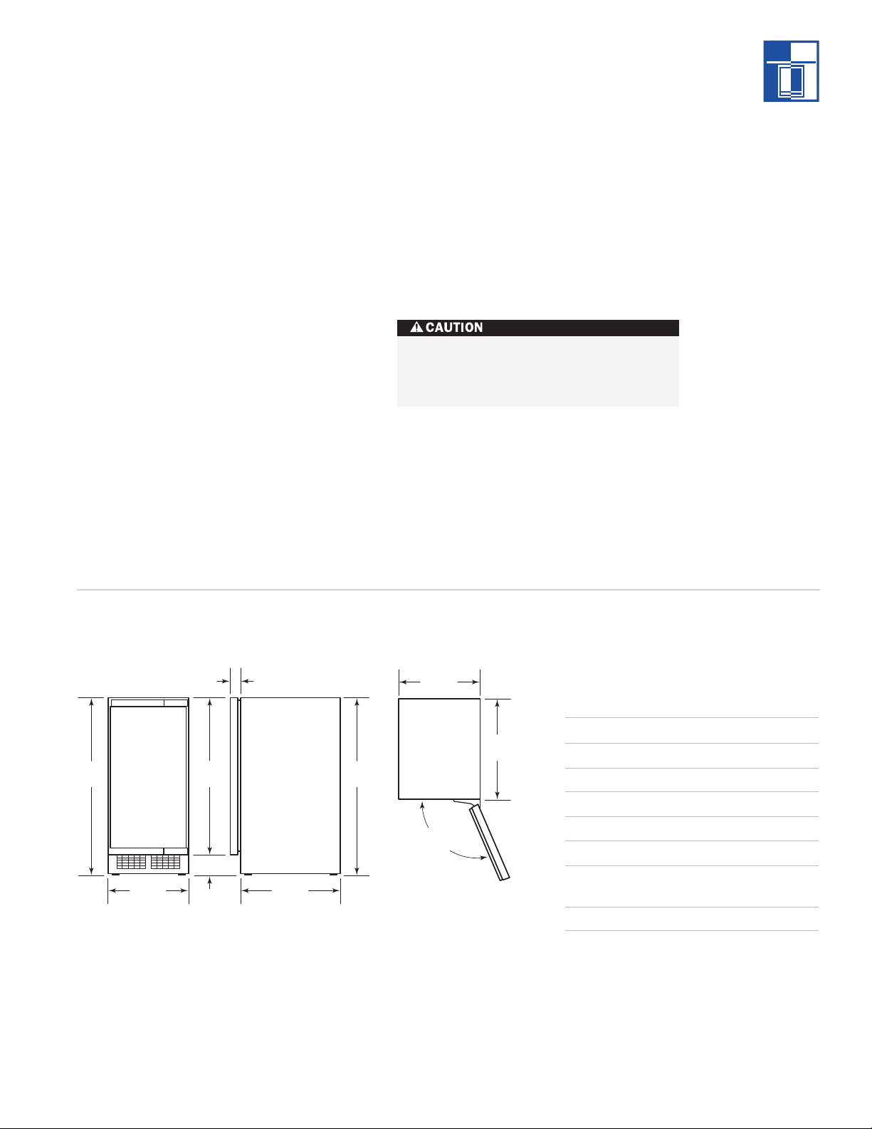
INSTALLATION SPECIFICATIONS
AREA REQUIREMENTS
Before moving the ice maker in place, be sure
the finished opening dimensions, electrical and
lumbing locations are accurate. Refer to the
p
Installation Specifications illustrations on
pages 7–8. The illustrations below provide
verall dimensions for Models 315I and 315IP.
o
Be sure your plumber, electrician and cabinet
installer have this information before finishing
work is completed.
Model 315I is a gravity drain model that
requires a drain tube that is pitched down from
the outlet at the back of the unit to the sanitary
sewer connection. Model 315IP has a built in
drain pump that will pump water up to a drain
point, such as a nearby sink. Refer to specifications on pages 7–8.
IMPORTANT NOTE:
If the ice maker is
installed in a corner, the door swing may be
limited due to handle contact with the wall or
cabinet face.
IMPORTANT NOTE:
ce maker must be at the same level as the
i
The floor under the
surrounding finished floor.
MPORTANT NOTE:When you move the unit
I
using a hand truck or dolly, position the dolly
on the side of the unit and secure the door so
t does not open while transporting the unit.
i
Any finished flooring should be protected
with appropriate material to avoid any
damage fr
om moving the unit.
O VERALL DIMENSIONS
Models 315I and 315IP
Dimensions may vary ±1/8" (3).
MODELS 315I AND 315IP
3
5
Overall Width
1
/16" (386)
Overall Height 335/8" (854)
Overall Depth 24" (610)
Minimum Door Clearance 151/4" (387)
1
5
Rough Opening W
idth
1
/4" (387)
Rough Opening Height 341/2" (876)
Minimum Height Required
(levelers in) 333/4" (857)
Rough Opening Depth 24" (610)
Dimensions may vary ±1/8" (3).
Dimensions in parentheses are in
millimeters unless otherwise specified.
5
Page 6

SUB-ZERO MODELS 315I AND 315IP INSTALLATION
IMPORTANT
NOTE
You must follow
all National
Electrical Code
regulations. In
addition, be aware
of local codes and
ordinances when
installing your
services.
ELECTRICAL REQUIREMENTS
A 115 V AC, 60 Hz, 15 amp circuit breaker and
lectrical supply are required. A separate
e
circuit is required for each unit.
he Model 315I(P) is equipped with a power
T
supply cord with a 3-prong grounding plug,
which must be plugged into a mating 3-prong
rounding-type electrical outlet.
g
Follow the National Electrical Code and local
codes and ordinances when installing the
receptacle. For location of the electrical supply,
refer to the Installation Specifications illustrations on pages 7–8.
IMPORTANT NOTE:
A ground fault circuit
interrupter (GFCI) is not recommended and
may cause interruption of operation.
Do not use an extension cord or twoprong adapter. Electrical ground is
required on this appliance. Do not remove
the power supply cord ground prong.
Shut off the power to the electrical
outlet.
PLUMBING REQUIREMENTS
Rough in the water supply line. Connect a 1/4”
D copper line to the house supply. Be sure to
O
use an easily accessible shut-off valve between
the supply and the unit. This shut-off valve
should not be installed behind the unit. Do not
use “self-piercing” valves. A saddle valve (part
#4-20-088-0) is available from your Sub-Zero
dealer. A line filter is required when the water
supply has a high mineral content. The water
supply must maintain 20 psi (1.4 bar) to 80 psi
(5.5 bar) of water pressure.
The water supply and drain should be roughed
in and ready at the point of installation. An
electrical outlet directly behind the ice maker
will make the installation easier. All electrical,
water and drain connections must conform to
local codes. For location of the water supply,
refer to the Installation Specifications illustrations on pages 7–8.
IMPORTANT NOTE:
Although the Model
315I(P) has been designed to be serviced in
place, in some cases it may be necessary to
pull the unit out for service. For that reason do
not restrict access to the unit at the front, top
and bottom.
If a floor is to be installed after the ice maker,
shims the thickness of the floor should be
installed under the Model 315I(P) to keep the
ice maker level with the floor. Also, allow 1/8"
(3) clearance on each side of the unit for
uding screw heads.
protr
Dimensions in parentheses are in
millimeters unless otherwise specified.6
Installations on a slab:
Use a Model 315IP,
with built-in drain pump and pump the water
to the point of drainage. Drain pump models
will pump one story high.
Installations over a crawl space or
basement:
Either a gravity drain (Model 315I)
or a drain pump (Model 315IP) unit may be
used. If there is not enough room behind the
ice maker for a
drain/waste water receptacle,
the drain will have to be below the floor.
IMPOR
TANT NOTE:
All plumbing must meet
local codes.
Page 7
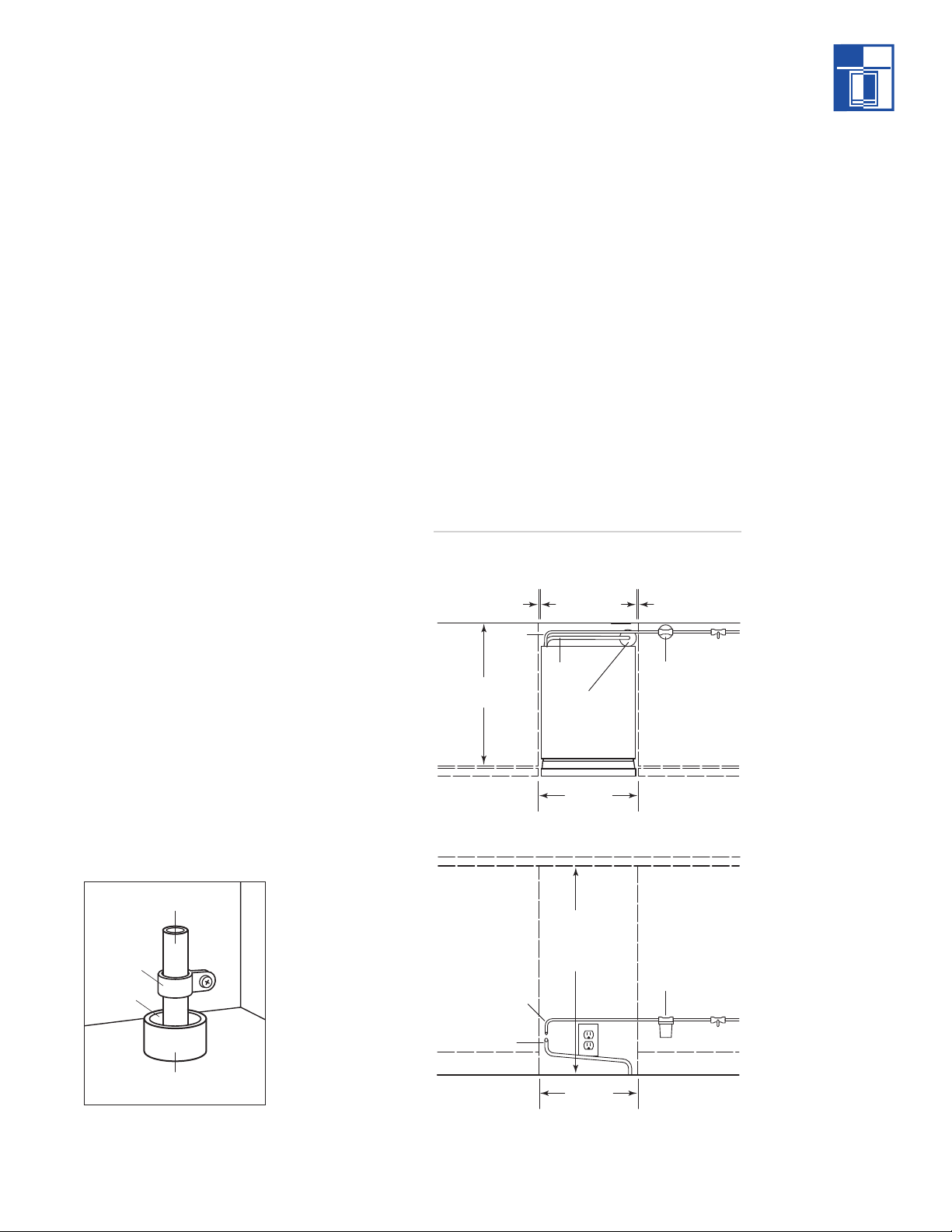
SUB-ZERO MODELS 315I AND 315IP INSTALLATION
151/4"
(387) MIN.
FRONT VIEW
SHUT-OFF
VALVE
WATER
FILTER
WATER
INLET TUBE
DRAIN
TUBE
TOP VIEW
SHUT-OFF
VALVE
WATER
FILTER
341/2"
(876) NOMINAL
333/4"
(857) MIN.
151/4"
(387) MIN.
24"
(610)
1
/8"
(3)
WATER
INLET
TUBE
DRAIN
TUBE
LOCATE DRAIN
WITHIN 2" DIA.
AREA 23" BACK
FROM FRONT
OF UNIT
Drain Tube
Stand Pipe
Drain
Clamp
MODEL 315I GRAVITY DRAIN
The drain and inlet water tubes must be
plumbed before connecting to the ice maker.
efer to the illustrations below. All horizontal
R
runs of drain lines must have a
1
/4" (6) per 12"
(305) fall. An air gap will likely be required
etween the ice maker drain tube and the
b
drain/waste water receptacle. A stand pipe
with a trap below it can be used for the
drain/waste water receptacle.
IMPORTANT NOTE:
Poor drainage will cause
a high rate of ice melting in the ice storage bin.
1)
Place the ice maker in front of the installation opening. Adjust leveling legs to the
approximate height.
2)
Remove the door (with hinges), control
knob, control panel, access panel and lower
face plate.
3)
Route the water inlet line (1/4" OD copper
tube) from the wall through the ice maker
to the front.
4)
Route the drain line from the wall position
through the ice maker. If you have a horizontal run longer than 5' (1.5 m), the drain
should be vented at the back of the unit.
9)
Attach the flare nut to the male flare on the
inlet water valve.
10)
Cut the drain tube to the required length.
11)
Connect the 5/8" drain tube to the storage
bin drain fitting at the bottom of the bin.
Secure with hose clamps. Be sure that the
drain tube is pushed up well past the barbs
on the drain fitting. If needed to ease installation, soak the drain hose in hot water just
before connecting to the fitting.
12)
Turn on the water supply and check for
leaks.
13)
Replace the door (with hinges), control
knob, control panel, access panel and lower
face plate. Level the unit as needed.
INSTALLATION SPECIFICATIONS
Model 315I
5)
6)
7)
8)
Drain tube detail
If the electrical outlet for the ice maker is
behind the unit, plug in the unit.
Position the unit in the installation opening.
Cut the water inlet line to the r
length.
Flush the water line. Place the flare nut on
the water line and flare the end of the
equir
ed
copper tube.
7
Page 8
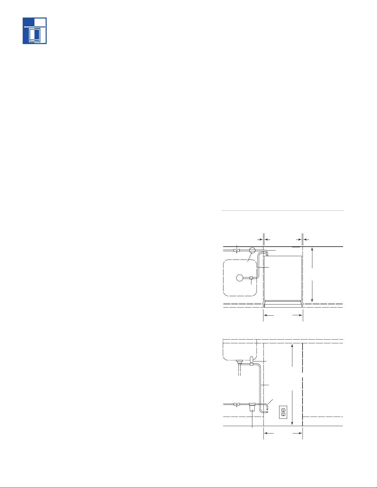
FRONT VIEW
SHUT-OFF
VALVE
WATER
FILTER
WATER
INLET TUBE
AIR GAP
DEVICE
DRAIN
TUBE
TOP VIEW
SHUT-OFF
VALVE
WATER
FILTER
WATER
I
NLET TUBE
DRAIN
TUBE
AIR GAP
DEVICE
24"
(609)
1
/8"
(3)
151/4"
(387) MIN.
151/4"
(387) MIN.
341/2"
(876) NOMINAL
333/4"
(857) MIN.
OPTIONAL
COMPONENTS
Optional installation components
are available
through your
Sub-Zero dealer.
You can also visit
our website at
subzero.com.
For installation
questions, call
Sub-Zero
Customer Service
at 800-222-7820.
SUB-ZERO MODELS 315I AND 315IP INSTALLATION
MODEL 315IP DRAIN PUMP
1)
Place the ice maker in front of the installation opening. Adjust leveling legs to the
pproximate height.
a
emove the control knob, control panel and
2)R
control access panel.
3)
Route the water inlet line (1/4" OD copper
tube) from the wall through the ice maker
to the front.
4)
Locate the coil of 3/8" ID plastic drain tubing
secured to the back of the unit.
DRAIN PUMP KIT
his ice maker can be ordered with a drain
T
pump (Model 315IP) or without (Model 315I).
Models without a pump drain their water by
ravity. However, gravity drain models may
g
be converted to pump models through the
installation of a drain pump kit.
The parts required for this conversion are
available through your Sub
can also visit the Locator section of our website,
subzero.com, to obtain information on the local
5)
Route the plastic drain tube from the back
of the unit to the drain connection point.
IMPORTANT NOTE:
Often an air gap is
required by local codes between the ice maker
drain tube and the drain receptacle. Refer to
parts distributor and/or dealer in your market.
Detailed installation instructions are included
with the kit.
Drain pump kit (#A36892020)
Drain pump (#12250321)
the illustration below.
6)
If the electrical outlet for the ice maker is
behind the unit, plug in the unit.
7)
Position the unit in the installation opening.
INSTALLATION SPECIFICATIONS
Model 315IP
-Zero dealer. You
8)
Cut the water inlet line to the required
length.
9)
Flush the water line. Place the flare nut on
the water line and flare the end of the
copper tube.
10)
Attach the flare nut to the male flare on the
inlet water valve.
urn on the water supply. Make sure that
11)
T
the ice maker is plugged in and the power
is on.
12)
Pour a couple of quarts of water into the ice
storage bin; the drain pump should start
and water should pump out. Check for
leaks.
13)
Replace the contr
ol knob, control panel and
control access panel. Level the unit as
needed.
ANT NOTE:
IMPOR
T
All plumbing must meet
local codes.
Dimensions in parentheses are in
millimeters unless otherwise specified.8
Page 9

SUB-ZERO MODELS 315I AND 315IP INSTALLATION
Flat Head
Screws
INSTALLATION
IMPORTANT NOTE:
Turn on the water supply
and check all fittings for leaks. Make sure the
lectrical harness is attached to the solenoid.
e
et your customer know that the ice maker will
L
not fill with water immediately and that the
first batch of ice produced should be
iscarded. Allow 24 to 36 hours for proper ice
d
production.
LEVELING
Level the Model 315I(P) by turning the leveling
legs counterclockwise to raise or clockwise to
lower.
To assist you in adjusting the front leveling
legs up or down, use a standard screwdriver
blade and place it in the front leveling leg to
turn.
SECURE THE ICE MAKER
To secure the ice maker, install two #8 x1/2" flat
head screws through each hinge. Refer to the
illustration below.
KICKPLATE/ GRILLE INSTALLATION
nce the ice maker is secured, you can install
O
the kickplate/grille. As shown in the illustration
below, there is some adjustment to the
ounting assembly so this decorative piece
m
can fit flush with the surrounding area.
D
O NOT cover the kickplate/grille area.
The unit must be allowed to have ventilation
through these fins. The door panel may hang
in front of the fins, but a decorative kickplate/
grille must not cover the fins.
The kickplate/grille can be painted another
color, if you choose. Follow these easy steps:
Rough up surface to be painted with fine
grit sandpaper.
Wipe with alcohol to ensure it is clean and
dry.
Use an appliance or industrial grade, oil
base, high gloss enamel paint.
Securing the ice maker
Kickplate/grille installation
9
Page 10

SUB-ZERO MODELS 315I AND 315IP INSTALLATION
INSTALLATION
SIDE PANELS
ith Model 315I(P), you must securely fasten
W
the side panels to the adjacent cabinets and
floor.
Panels should be fastened to the floor and
walls using ’L’ brackets (hardware not
provided). To help you move the unit into
place, rout out an area in the floor so the ‘L’
bracket will sit flush with the floor level.
Brackets and screws are provided for
mounting the unit to adjoining cabinets and
side panels.
REVERSE THE DOOR SWING
The hinged side of the door may be reversed
to the other side if desired.
The Model 315I(P) is shipped with the door
hinged at the right. The door and hinges are
designed for placing the hinges on either the
right or the left side of the unit. Moving the
hinges to the left in the pre-drilled holes,
allows the door to pivot from the left side.
Refer to the illustrations below.
IMPORTANT NOTE:
The plastic molding
which covers the top area of the door,
packaged with the ice maker, is required for
this procedure.
1)
Remove the hinge cover.
2)
Remove the door by removing the four
screws that secure the door to the door
inges.
h
3)
Remove the door hinges by removing the
four screws that secure them to the unit.
4)
Remove the four screws from the opposite
hinge side (or left-hand hinge mounting
holes) and reposition into the right-hand
hinge mounting holes.
5)
Install the hinges using the left-hand
cabinet mounting holes.
6)
Install the door using the left-hand door
mounting holes.
7)
Remove the two screws which secure the
upper door panel mounting bracket.
8)
Install the upper door panel mounting
bracket using the left-hand mounting holes.
9)
Install the left-hand door hinge cover with
the original screws.
10)
Check the operation of the door by opening
and closing it.
Dimensions in parentheses are in
millimeters unless otherwise specified.10
Right-hand door swing
Left-hand door swing
Page 11

SUB-ZERO MODELS 315I AND 315IP INSTALLATION
Flush with Top and Side
of Panel
INSTALLATION
DOOR PANEL INSTALLATION
ou should be sure of the door panel size and
Y
placement before proceeding with the installation. If you have questions, contact your
ub-Zero dealer or cabinet supplier. Instruc-
S
tions regarding sizing of the door panel are
provided in the Sub-Zero Design Guide.
For door handle hardware, a D-style pull
centered on the edge opposite the door hinge
side is recommended. Screw heads may have
to be countersunk to ensure that the hardware
does not interfere with the panel fitting flush
with the unit door.
MODELS 315I AND 315IP
Door Panel Width – 1/8" (3) reveal 15" (381)
Door Panel Height – 1/8" (3) reveal
4" (102) toe space 303/8" (772)
Door Panel Thickness
5
/8" (16) min
Door Panel Weight 15 lbs (6.8 kg) max
1
Dimensions may vary
+_
/8" (3).
Remove the handle side bracket attached to
the front of the door and set aside.
Place the door panel lying face down on a
rotected surface to ensure the front is not
p
scratched or damaged.
Position the plastic template provided flush
with the upper edge of the door. Be sure you
are following the exact location for the RH or
LH door position. Refer to the illustration
below.
IMPORTANT NOTE:
Remember you are
viewing the door panel from the back side in
the illustration. The overall size of the panel
shown is the minimum size necessary to cover
the door of the unit. The exact measurements
of your door panel may vary depending on the
particular installation you are following.
Once you have located the proper position for
the hardware, mark the holes, remove
template, and drill pilot holes for mounting of
the hardware. We recommend starting the first
few holes, positioning the hardware, drilling
remaining pilot holes, and securing the
1
mounting brackets with the #8 x
/2" screws.
Refer to the illustrations below.
PANEL
DESIGN
Additional panel
design information
can be found in
the Sub-Zero
Design Guide.
Check our website
at subzero.com.
Template position
Right-hand door panel
Left-hand door panel
11
Page 12

Door Stop Pin
Knock-Out
SUB-ZERO MODELS 315I AND 315IP INSTALLATION
INSTALLATION
90-DEGREE DOOR STOP
Exercise caution when drilling holes for
mounting hardware. This is especially
critical with inset panels.
Install the door panel by engaging the tabbed
bracket to the door first and then sliding the
hinge side hardware over the positioning
screws. You will have a 1/4" inch adjustment,
up and down, side to side, with this hardware.
Once you have the door in place, attach the
1
remaining #8 x
/2" screws to the hinge side
mounting bracket and install decorative caps.
If the reveal on the hinge side of the door
panel is less than
a square corner, severe finger pinching or
damage to the unit may occur.
1
/4", and the panel has
odel 315I(P) has a 90-degree door stop.
M
Follow these steps for installation:
1)
Open the door approximately 80 degrees.
2)
Insert the stop pin into the bottom door
inge (pin enters from the top). The pin
h
must be inserted until the head has made
contact with the hinge body. Refer to the
illustration below.
3)
Insert the stop pin into the top door hinge
(pin enters from the bottom).
4)
Check for proper operation.
HINGE COVER INSTALLATION
IMPORTANT NOTE:
Install the hinge covers
after installation of the ice maker is complete.
The 90-degree door stop must be installed
prior to installing the hinge covers.
1)
Remove the backing paper of the adhesive
pads and bond to the hinge.
2)
Install center covers (magnets will secure
these covers). Refer to the illustration
below.
IMPORTANT NOTE:
dirt or grease before applying covers.
IMPORTANT NOTE:
emove the knock-out in the hinge cover when
r
the 90-degr
90-degree door stop
Hinges must be free of
It will be necessary to
ee door stop is used.
Hinge cover installation
12
Page 13

SUB-ZERO MODELS 315I AND 315IP INSTALLATION
INSTALLATION CHECKLIST
IMPORTANT NOTE:
To ensure a safe and
proper installation, the following checklist
hould be completed by the installer to ensure
s
that no part of the installation has been
overlooked.
Any questions or problems about the installa-
ion should be directed to your Sub-Zero
t
dealer or Sub-Zero Customer Service at
800-222-7820. You can also visit our website
at subzero.com.
Is the unit operating? If not, is the unit
plugged in? Check to see if the unit is
operating before you install.
Has the unit been properly uncrated, and
have all packing materials and tape been
removed from inside the unit?
Have the installation instructions been
followed?
Has the unit been leveled?
Is the kickplate/grille installed?
If applicable, is the door panel installed
properly?
If you are storing or disposing of your old
refrigerator or freezer, please do it safely.
Remove the doors or tightly secure the
doors closed. Child entrapment accidents
can be tragic.
CONTACT
INFORMATION
Sub-Zero
Customer Service:
800-222-7820
Website:
subzero.com
Does the customer understand the unit’s
operation?
Have any installation or service problems
been noted on the product registration
d? Instruct the owner to register the
car
product.
Dimensions in parentheses are in
millimeters unless otherwise specified.
13
Page 14

SUB-ZERO MODELS 315I AND 315IP FEATURES
MODELS 315I AND 315IP FEATURES
WARRANTY
Sub-Zero products
are covered by a
two, five and
twelve year residential warranty
(exclusions apply).
See warranty
details at the end
of this guide.
Undercounter ice maker
Model 315I has a gravity drain, while Model
315IP has a built-in pump to allow water to
rain into adjacent sink
d
24" (610) depth-true design for a complete
integrated look
Door accepts custom panels
Automatic ice maker provides high-quality,
clear ice
Ice storage bin capacity of up to 26 lbs
(12 kg)
Automatic defrost
Reversible door swing
Front venting with removable kickplate/
rille allows unit to be serviced from the
g
front
olid core door with magnetic gasket and
S
door closer
UL approved for US and Canada
Two, five and twelve year residential
warranty – exclusions apply, see warranty
at the end of this guide
MODEL 315I
Ice Maker
Automatic ice maker
Water reservoir
Large capacity
ice storage bin
Serial and model
number plate
Front venting with
removable kickplate/grille
Reversible door hinge
Ice scoop
Four sided magnetic
gasket
Adjustable ice maker
control
14
Page 15

SUB-ZERO MODELS 315I AND 315IP OPERATION
ICE MAKER OPERATION
INITIAL START-UP
emove the control box cover.
1)R
2)
Rotate timer shaft clockwise until the cam is
in the harvest position (switch button out).
3)
Turn on the water supply.
4)
With unit plugged in, rotate the ice maker
control knob to the ON position.
5)
Allow the ice maker to operate for one hour,
and check the size of the cubes; if they are
not correct, adjust as recommended on
page 18.
6)
After the cubes are confirmed to be the
correct size, replace all panels.
USING YOUR ICE MAKER
The ice maker is extremely simple to use; by
turning the ice maker control knob to the ON
position. The Model 315I(P) will automatically
begin to produce ice and will continue to do so
until the ice storage bin is full.
Use the scoop to remove ice and place the ice
scoop in the holder provided (do not leave the
scoop on the ice, as it will gradually disappear
into the ice).
The Model 315I(P) will release a batch of eight
ice cubes about every 30 minutes. At the same
time the cubes fall into the ice storage bin,
water will be entering the ice maker and
draining out.
IMPORTANT NOTE:
Do not store anything in
the ice storage bin other than ice; items like
wine or beer bottles are not only unsanitary,
but labels may also slip off and plug the drain.
ICE CUBES
he ice cubes are tapered cylinders about 1
T
1
/4"
(32) in diameter at the widest end; taper down
to 1" (25) wide at the top; and are 1
igh. When the ice maker is adjusted properly,
h
there should be a
1
/4" (6) indent in the base of
1
/8" (29)
the cube. The ice will appear wet when fresh
and may also develop frost on the outside and
look cloudy. This is normal. The frost will
disappear when liquid is poured over the ice.
ICE STORAGE BIN
All restaurant-type ice makers, such as the
Model 315I(P), operate on this principal: The
ice storage bin is not refrigerated; instead it’s
heavily insulated, much like a picnic cooler or
ice chest. If the ice storage bin were to be
refrigerated, the ice would freeze together into
one very large cluster of ice and would begin
to evaporate. This would yield ice that is very
poor in quality and difficult to remove from the
ice maker.
The Model 315I(P) will continue to operate
until ice builds up high enough to contact thermostat sensor tube in the ice storage bin; then
it will shut off. Models with a drain pump will
occasionally pump out melt water when the ice
maker is off. The pump will only be on for a
few seconds.
RUN TIME
The amount of time the Model 315I(P) will run
to replace melted ice is about two hours per
day. The amount of time the ice maker will run
to replace ice removed is dependent upon how
much ice is removed, how clean the ice maker
is, the surrounding air temperature and the
temperature of the water supplied to the ice
maker. An empty ice maker will usually take
about 24–36 hours to refill.
15
Page 16

SUB-ZERO MODELS 315I AND 315IP OPERATION
ICE PRODUCTION
Ice production has two distinct cycles: freeze
and harvest. One freeze cycle and one harvest
ycle will yield a batch of eight ice cubes.
c
he freeze cycle occurs when water is sprayed
T
against the freezing surface. The harvest cycle
occurs when the ice is released and water
nters the ice maker. A complete cycle takes
e
about 30 minutes.
FREEZE CYCLE
During the freeze cycle the compressor is
pumping refrigerant, the fan motor is blowing
air, and the water pump is circulating water. As
the refrigerated surface absorbs heat from the
water sprayed against it, that heat is moved to
the area where the fan is blowing air. The heat
is transferred to the air, and the warmed up air
is discharged from the ice maker. At the same
time, ice is forming on the refrigerated surface
(located at the upper back of the ice maker).
When the refrigerated surface gets cold
enough, the ice maker’s timer will begin to
turn. When it turns far enough, it will stop the
freeze cycle and begin the harvest.
HOW THE ICE MAKER USES WATER
he ice maker begins with a fixed charge of
T
water that is contained in the reservoir. As the
water is sprayed against the freezing surface,
he part of water that does not contain mineral
t
impurities will freeze and stick to the ice cup
molds. The water containing impurities falls
back into the reservoir. Gradually, during the
freezing portion of the ice making cycle, the
water in the reservoir will become highly
concentrated with mineral impurities.
During the harvest cycle fresh water flows into
the ice maker to dilute the reservoir water and
to rinse the concentrated minerals down the
drain.
HARVEST CYCLE
During the harvest cycle the compressor is still
operating, but the spray pump and fan motor
have stopped. Two other components have
been energized: the hot gas valve and the inlet
water valve. These two valves open and warm
up the freezing surface, allowing the cubes to
fall into the ice storage bin. The timer is still
turning, and when it gets to the end of the
harvest cycle, the freeze cycle will restart.
16
Page 17

SUB-ZERO MODELS 315I AND 315IP OPERATION
Condenser
CLEANING
Make sure that the outside of the unit and
door, ice storage bin, condenser, ice making
ystem and ice scoop are kept clean.
s
ever allow the ice maker to operate without
N
regular cleaning. The ice maker will last longer
if it is kept clean. Regular cleaning should be
one at least once per year, and preferably
d
twice. Some water conditions will dictate more
frequent cleaning of the ice making system
and some carpets or pets will dictate more
frequent cleaning of the condenser.
EXTERIOR CLEANING
Wipe off any spills on the surface of the door
and handle as they occur. If anything spilled on
the door or gasket dries onto the surface, wash
with soap and warm water to remove. Always
use a nonabrasive cloth or pad.
To clean the exterior of a stainless steel model,
use a soft, nonabrasive stainless steel cleaner
like Signature Polish (see side note) and apply
with a soft 100% lint-free cloth.
CLEANING THE ICE STORAGE BIN
he ice storage bin should be sanitized occa-
T
sionally. It is usually convenient to sanitize the
bin after the ice making system has been
leaned, and the ice storage bin is empty.
c
A sanitizing solution can be made of one ounce
of household bleach and two gallons of hot
95˚F–115˚F (35˚C–45˚C) water. Use a clean cloth
and wipe the interior of the ice storage bin
with the sanitizing solution; pour some of the
solution down the drain and allow it to air dry.
CLEANING THE CONDENSER
The condenser should be vacuumed two to
three times per year to remove any lint that
may have been drawn into the condenser.
To access the condenser, use a phillips head
screw driver to remove the kickplate/grille.
Then, using a soft bristle brush, vacuum to
remove dust and lint from the condenser. Refer
to the illustration below for location of the
condenser.
SIGNATURE
POLISH
Signature Polish
is available from
Signature Limited
Laboratory,
P. O. Box 13436,
Dayton, Ohio
45413-0436, or
call 877-376-5474
(toll free).
For maintenance and cleaning, it is
recommended that the circuit breaker to
the unit or the on/off control be shut off.
IMPORTANT NOTE:
To avoid bending the
condenser fins, be sure to vacuum in the
direction of the fins (up and down).
Failure to clean the condenser could
result in temperature loss or mechanical
failure or damage.
Condenser location
17
Page 18

SUB-ZERO MODELS 315I AND 315IP OPERATION
ICE MAKER
CLEANER
Sub-Zero ice
maker cleaner
(8 oz. bottle) is
available from
your Sub-Zero
dealer. Ask for part
#19034306.
ICE MAKER CLEANING
CLEANING THE ICE MAKING SYSTEM
pen the door and turn the ice maker
1)O
control knob to OFF. Refer to the illustration
on page 19 for location of the control knob.
2)
Scoop out all of the ice; either discard it or
save it in a ice chest or cooler.
3)
Pour four ounces of Sub-Zero ice maker
cleaner into the ice maker reservoir (see
side note).
4)
Turn the ice maker control to ON.
5)
Allow the ice maker to operate for about
two hours.
6)
Pour hot water 95˚F–115˚F (35˚C–45˚C) into
the ice storage bin to melt the ice that has
formed. That ice will likely be white and
frosty looking.
7)
Clean the ice storage bin liner of mineral
scale by mixing some ice maker cleaner
and hot water, using that solution to scrub
the scale off of the liner.
8)
Rinse the liner with hot water.
9)
Sanitize the ice storage bin interior.
10)
Replace the ice removed in step 2. The ice
scoop should be washed regularly; wash it
just like any other food container.
ICE MAKER MAINTENANCE
WINTERIZING
lean the ice making system.
1)C
2)
Turn off the water supply.
3)
Drain the water reservoir. Remove the
pump hose.
4)
Disconnect the incoming water line at the
inlet water valve.
5)
Remove control box cover and turn the
timer into the harvest cycle.
6)
With the ice maker operating, blow air
through the inlet water valve; a tire pump
could do the job.
7)
Drain pump models should have about
one-half gallon of RV antifreeze (propylene
glycol) poured into the ice storage bin
drain.
IMPORTANT NOTE: DO NOT
use automotive
antifreeze.
8)
Replace control box cover. Turn the ice
maker OFF and unplug the unit.
To use the ice maker after winterizing, reconnect the pump hose and water line. Repeat the
initial start-up steps outlined on page 15.
ICE MAKER ADJUSTMENTS
18
Sub-Zer
These compounds may cause burns.
If swallowed, DO NOT induce vomiting.
Give large amounts of water or milk. Call
a physician immediately
contact, flush with water
reach of children.
o ice maker cleaner contains acids.
. In case of skin
. Keep out of the
There are three items that may be adjusted:
cube size, storage bin ice level and harvest
time.
IMPORTANT NOTE:
Cube size and harvest
time adjustments should only be done by a
authorized service center technician.
o
Zer
Sub-
CUBE SIZE ADJUSTMENT
The cube size control should only be adjusted
to bring the ice cubes to the correct shape; the
overall size cannot be adjusted. Try to adjust
the cube size control when the ice maker is in
the harvest cycle, or in the first ten minutes of
the freeze cycle.
Page 19

SUB-ZERO MODELS 315I AND 315IP OPERATION
Control Knob
Cube Size Adjustment
1)
Open the door and remove the control box
over.
c
2)
Locate the cube size adjustment screw
hown in the illustration below. To make
s
fuller cubes, turn the screw clockwise about
1
/4 turn. This will make the freezing cycle
onger.
l
3)
To shorten the freezing cycle and make
cubes that are not as full, turn the adjust-
1
ment screw
4)
After the next freezing cycle, the cubes
/4 turn counterclockwise.
should have responded to the adjustment;
if another adjustment is required, do it early
in the freeze cycle.
STORAGE BIN LEVEL ADJUSTMENT
When the ice maker shuts off, the ice level in
the storage bin should be even with the metal
tube inside the bin. If the ice in the storage bin
is too high or too low, turn the ice maker
control knob to adjust the ice storage bin
thermostat. Refer to the illustration below.
To lower the ice level, turn the knob counter-
HARVEST TIME ADJUSTMENT
The amount of harvest time may be adjusted.
It is preset from the factory at about three
inutes, which should be adequate to release
m
all cubes and fill the reservoir. If the timer
needs to be adjusted, follow these steps:
1)
Unplug the ice maker or disconnect the
electrical power.
2)
Remove the kickplate/grille.
3)
Remove the control box cover.
4)
Locate the timer shown in the illustration
below. Loosen the set screw that holds the
two halves of the timer cam together.
5)
Rotate one half of the cam to open or close
the lower portion of the cam. More of an
opening equals more harvest time and less
of an opening means less harvest time.
6)
Tighten the set-screw.
7)
Replace the control box cover and kickplate/
grille.
8)
Reconnect the electrical power.
clockwise. To increase the ice level, turn the
knob clockwise. Usually a
enough for either adjustment.
1
/8 turn will be
Electrical Shock Hazard—Disconnect
electrical power before beginning
removal of parts.
Ice maker control knob
Cube size adjustment
Harvest time adjustment
19
Page 20

SUB-ZERO TROUBLESHOOTING GUIDE
TROUBLESHOOTING GUIDE
ROBLEM POSSIBLE CAUSE POSSIBLE SOLUTION
P
SERVICE
CENTER
Contact your
Sub-Zero dealer or
check the Locator
section of our
website,
subzero.com, for
the authorized
service center
nearest you.
ce maker does not
I
operate
Ice cubes are too
large
Ice cubes are too
small
ce maker is unplugged Plug ice maker in
I
Breaker tripped or fuse is blown Reset breaker or replace fuse –
f it happens again, call a Sub-Zero
i
authorized service center
Ice maker control turned to OFF Turn ice maker control to ON
Storage bin thermostat open, Ice on sensor tube – it is normal for
keeping ice maker off ice maker to be off
Ice maker in room below 50˚F (10˚C)
– room must be warmer for ice
maker to operate
Storage bin thermostat stuck open,
must be replaced
Timer contacts open Replace timer
Cube size control set too cold Adjust cube size control for smaller
cubes (see page 18)
Cube size control set too warm Adjust cube size control for larger
cubes (see page 18)
Not enough water Check water supply – filter may
be restricted
Check inlet water valve – inlet screen
may be restricted
Cube size control stuck closed – Replace timer
timer runs all the time
20
tially
Ice cubes ar
med – ragged sides
for
e par
Ice maker makes ice,
but storage bin does
not fill with ice
Ice cubes are partially
med – white at the
for
bottom
Spray jets par
tially clogged
Clean ice making system with ice
maker cleaner (see page 18)
Storage bin should fill with ice and Clean condenser (see page 17)
ice maker shut off in 24–36 hours –
if not, condenser may be dirty
Storage bin drain may be partially Clean out drain, check installation
estricted
r
Air flow to ice maker may be Check installation – kickplate/grille
obstr
ucted
must be fr
ee of obstr
uctions
Not enough water in reservoir Check water supply – filter may
may be r
estricted
Check inlet water valve – inlet screen
may be r
estricted
Check for water leak in reservoir
Page 21

SUB-ZERO TROUBLESHOOTING GUIDE
TROUBLESHOOTING GUIDE
ROBLEM POSSIBLE CAUSE POSSIBLE SOLUTION
P
nit operates
U
but no ice falling in
storage bin
ce may be stuck in the evaporator Check water supply – filter may
I
and the unit is ”frozen up” be restricted
heck inlet water valve – inlet screen
C
may be restricted or valve does not
operate
ot gas valve may not operate –
H
check and repair or replace
Harvest time set too short – timer
needs adjustment (see page 19)
Too much heat load Inlet water valve leaks through,
must be replaced
No water spray Water pump does not operate, must
be replaced or check for water
leak in reservoir
No airflow Fan motor does not operate or fan
blade is broken, must be replaced
Condenser completely blocked,
must be cleaned (see page 17)
Cube size control will not close Defective control, must be replaced
Inlet water valve leaks through,
must be replaced or not enough
-Zero
refrigerant, call a
authorized service center
Compressor does not operate Start relay or capacitor must be
properly or at all replaced
Call a Sub-Zero authorized service
center
-Zero authorized service
Sub
Not enough r
Restricted system Call a Sub-Zero authorized service
Hot gas valve leaks through Call a Sub-Zero authorized service
efrigerant
Call a
center
center
center
Sub
21
Page 22

SERVICE INFORMATION
SERVICE INFORMATION
CONTACT
INFORMATION
Sub-Zero
Customer Service:
800-222-7820
Website:
subzero.com
If you do need service, be sure to have the
model and serial number of your unit when
ou call. You’ll find these numbers on the
y
model and serial number plate located on the
left sidewall of the reservoir. For warranty
urposes, you will also need the date of
p
installation and the name of your Sub-Zero
dealer. Record this information below for
future reference.
Model Number
Serial Number
Installation Date
Sub-Zero Authorized Service Center and Phone
Sub-Zero Dealer and Phone
BEFORE CALLING FOR SERVICE
PRODUCT REGISTRATION
egister your new Sub-Zero today so that we
R
may ensure your satisfaction. You may register
by one of the following options:
1)
Mail in the completed Sub-Zero Product
Registration Card.
2)
Register online at
3)
Register by phone by calling the Sub-Zero
subzero.com
.
Customer Service Department at
800-222-7820
.
The model and serial numbers of your unit
are printed on the enclosed Sub-Zero Product
Registration Card. If you provide us with your
e-mail address, we will send you exciting new
product updates and recipes as they become
available, along with information on special
events.
22
Before calling a Sub-Zero authorized service
center, refer to the Troubleshooting Guide on
pages 20–21. Check the household fuse or
circuit breaker to see if it has been blown or
tripped and that the electrical connection to
the appliance has not been disconnected.
A power outage may also have caused a
disruption in service.
The infor
copyright pr
Inc. Neither this book nor any information or
images contained her
in whole or in par
permission of Sub-Zero Freezer Company, Inc.
©Sub-Zero Freezer Company, Inc. all rights
reserved.
mation and images in this guide ar
ty of Sub-Zer
oper
ein may be copied or used
t without the expr
o Freezer Company,
ess written
e the
Page 23

S UB-Z ERO F REEZER C OMPANY P RODUCTS
L IMITED W ARRANTY
RESIDENTIAL USE ONLY
ULL FIVE YEAR SEALED SYSTEM WARRANTY
F
LIMITED SIXTH THROUGH TWELFTH YEAR WARRANTY ON THE SEALED SYSTEM
FULL TWO YEAR WARRANTY ON TOTAL PRODUCT*
FULL FIVE YEAR SEALED SYSTEM WARRANTY
For five years from the date of original installation, your Sub-Zero warranty covers all parts and labor
to repair or replace any components that prove to be defective in materials or workmanship in the
ealed system. The sealed system consists of the compressor, condenser, evaporator, drier and all
s
connecting tubing.
FULL TWO YEAR WARRANTY*
For two years from the date of original installation, your Sub-Zero warranty covers all parts and
abor to repair or replace any part of the product, that proves to be defective in materials or work-
l
manship.
LIMITED SIXTH THROUGH TWELFTH YEAR SEALED SYSTEM WARRANTY
From the 6th through the 12th year from the date of original installation, your Sub-Zero warranty
covers all parts that prove to be defective in materials or workmanship in the sealed system (parts
only). The sealed system consists of the compressor, condenser, evaporator, drier and all connecting
tubing.
TERMS APPLICABLE TO EACH WARRANTY
All service provided by Sub-Zero under the above warranty must be performed by an authorized
Sub-Zero service center, unless otherwise specified by Sub-Zero. Service will be provided in the
home during the normal business hours. This warranty applies only to products installed for normal
residential use. Details regarding a non-residential warranty are available upon request.
The warranty applies only to products installed in any one of the fifty states of the United States, the
District of Columbia or the ten provinces of Canada. This warranty does not cover any parts or labor
to correct any defect caused by negligence, accident or improper use, maintenance, installation,
service or repair, including but not limited to improper removal and reinstallation (whether in the unit
or at a remote location) of the condensing unit.
THE REMEDIES DESCRIBED ABOVE FOR EACH WARRANTY ARE THE ONLY ONES THAT
WARRANTIES OR UNDER ANY WARRANTY
SUB-ZERO
ARISING BY OPERA
QUENTIAL OR INCIDENTAL DAMAGES ARISING FROM THE BREACH OF THESE WARRANTIES
ANY O
OR
Some states do not allow the exclusion or limitation of incidental or consequential damages, so the
above limitation or exclusion may not apply to you. This warranty gives you specific legal rights and
you may also have other legal rights, which vary from state to state.
o receive parts an
T
contact y
ment, P. O. Box 44130, Madison Wisconsin, 53744-4130; check the Locator section of our website,
subzero.com, or call 800-222-7820.
* Stainless Steel (classic, platinum and carbon) doors, panels, product frames and stainless interior
surfaces are covered by a limited 60 day parts and labor warranty for cosmetic defects.
* Replacement water filter cartridges are not covered by the product warranty.
WILL PRO
THER WARRANTIES, WHETHER EXPRESS, IMPLIED OR STATUTORY.
our Sub-Zer
VIDE, EITHER UNDER
TION OF LAW. SUB-ZERO WILL NOT BE RESPONSIBLE FOR ANY CONSE-
/or service and the name of the Sub-Zero authorized service center nearest you,
d
o dealer
, distributor or Sub-Zer
THESE
reezer Company
o F
, Customer Service Depart-
23
Page 24

S
UB-ZERO FREEZER COMPANY, INC. P.O. BOX 44130 MADISON, WI 53744-4130 800-222-7820 SUBZERO.COM
17307901
8/2005
 Loading...