

Page 1

PL-2000
Operation Manual
Page 2

PL-2000
Operation Manual
SubSurface Instruments, Inc.
1230 Flightway Drive
De Pere, WI 54115
Phone: (920) 347-1788
FAX: (920) 347-1791
Web: www.ssilocators.com
Page 3

INDEX1STANDARD INSTRUMENT
STANDARD INSTRUMENT. . . . . . . . . . . . . . . . . . . . . . . . . . . . . . . . . . . . . . . . . . . . . 1
OPTIONAL ACCESSORIES . . . . . . . . . . . . . . . . . . . . . . . . . . . . . . . . . . . . . . . . . . . . 2
OPERATION OF TRANSMITTER
Transmitter Unit, Operation Panel . . . . . . . . . . . . . . . . . . . . . . . . . . . . . . . . . . . . 3
Connections, LCD Display of Transmitter . . . . . . . . . . . . . . . . . . . . . . . . . . . . . . 4
Automatic OFF Function . . . . . . . . . . . . . . . . . . . . . . . . . . . . . . . . . . . . . . . . . . . 5
OPERATION OF RECEIVER
Receiver Unit, Receiver Operation Panel. . . . . . . . . . . . . . . . . . . . . . . . . . . . . . . 6
LCD Display of Receiver . . . . . . . . . . . . . . . . . . . . . . . . . . . . . . . . . . . . . . . . . . . 7
Four Operating Modes in Reciever . . . . . . . . . . . . . . . . . . . . . . . . . . . . . . . . . . . 8
Mode Displays . . . . . . . . . . . . . . . . . . . . . . . . . . . . . . . . . . . . . . . . . . . . . . . . . . . 9
How to read Current Measurement . . . . . . . . . . . . . . . . . . . . . . . . . . . . . . . . . . 10
REPLACEMENT OF BATTERIES
Transmitter: How to change the batteries. . . . . . . . . . . . . . . . . . . . . . . . . . . . . . 11
Receiver: How to change the batteries . . . . . . . . . . . . . . . . . . . . . . . . . . . . . . . 12
HOW TO OPERATE THE TRANSMITTER . . . . . . . . . . . . . . . . . . . . . . . . . . . . . . . . 13
HOW TO OPERATE THE RECEIVER . . . . . . . . . . . . . . . . . . . . . . . . . . . . . . . . . . . . 14
MESSAGES DISPLAYED ON THE LCD DISPLAYS
Transmitter Displays, Receiver Displays . . . . . . . . . . . . . . . . . . . . . . . . . . . . . . 15
OPERATION IN THE FIELD
Peak Mode . . . . . . . . . . . . . . . . . . . . . . . . . . . . . . . . . . . . . . . . . . . . . . . . . . . . . 16
Null Mode . . . . . . . . . . . . . . . . . . . . . . . . . . . . . . . . . . . . . . . . . . . . . . . . . . . . . . 17
Inductive Mode . . . . . . . . . . . . . . . . . . . . . . . . . . . . . . . . . . . . . . . . . . . . . . . . . . 18
Operation by One Operator Alone . . . . . . . . . . . . . . . . . . . . . . . . . . . . . . . . . . . 19
Direct Connection Mode. . . . . . . . . . . . . . . . . . . . . . . . . . . . . . . . . . . . . . . . . . . 20
Loop Mode . . . . . . . . . . . . . . . . . . . . . . . . . . . . . . . . . . . . . . . . . . . . . . . . . . . . . 22
Inductive Clamp Mode . . . . . . . . . . . . . . . . . . . . . . . . . . . . . . . . . . . . . . . . . . . . 23
Radio Mode . . . . . . . . . . . . . . . . . . . . . . . . . . . . . . . . . . . . . . . . . . . . . . . . . . . . 24
Sonde Mode . . . . . . . . . . . . . . . . . . . . . . . . . . . . . . . . . . . . . . . . . . . . . . . . . . . . 25
Live Cable Mode . . . . . . . . . . . . . . . . . . . . . . . . . . . . . . . . . . . . . . . . . . . . . . . . 26
How to measure the depth . . . . . . . . . . . . . . . . . . . . . . . . . . . . . . . . . . . . . . . . . 27
How to measure the depth of parallel pipes . . . . . . . . . . . . . . . . . . . . . . . . . . . . 28
APPLICATIONS
How to locate parallel pipes (by Inductive Mode). . . . . . . . . . . . . . . . . . . . . . . . 29
How to locate parallel pipes (by Direct Connection Mode). . . . . . . . . . . . . . . . . 30
Locating branches in pipelines and water services from the main . . . . . . . . . . . 31
WARRANTY. . . . . . . . . . . . . . . . . . . . . . . . . . . . . . . . . . . . . . . . . . . . . . . . . . . . . . . . 32
Page 4

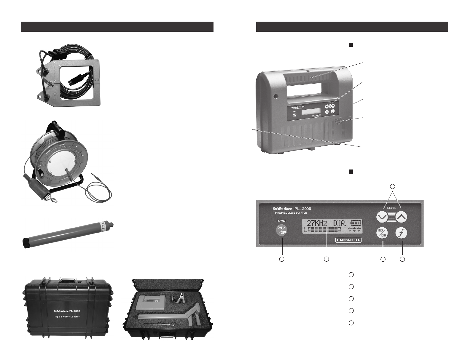
1. Transmitter Unit operated with
8 D batteries
2. Receiver Unit operated with
6 AA batteries
3. Direct Mode Cables
and Ground Stake
4. Soft Carrying Case
Page 5
2
3
1. Inductive Clamp and Cables.
Handle
Operation Panel
Direct Mode Connection
Battery Compartment Cover
Serial Number Plate
1 2 3
4
5
Use the inductive clamp (4 inch opening) for energizing telephone cables and
power cables inductively.
2. Cable Drum with 50 meter cable.
It can be used in the Loop Cable mode
to put a strong signal on a target line, or
when you can’t get a good ground. You
can also make up your own Loop Cable
if you prefer.
OPERATION OF TRANSMITTEROPTIONAL ACCESSORIES
Transmitter Unit
Operation Panel
3. 8 KHz Sonde.
Locate plastic pipes, clay-pipe sewers,
etc. by pushing/pulling a sonde transmitter through them.
4. Heavy-Duty ABS Plastic Hard Case.
Transport the PL-2000 in a custom-foam
hard case for maximum protection.
1
Power Switch, On/Off
2
Mode Selection Switch
3
Frequency Selection Switch
4
Output Power Level Switches
5
LCD Display
Page 6
4
5
OPERATION OF TRANSMITTEROPERATION OF TRANSMITTER
Su bS ur fa c e
PL–2000
k Hz
L
L[ ]
PO WE R O F F
DIR.CABLE
DC12V
6
7
A B C
D E
CO NT IN UO U S
Su bS ur fa c e
PL–2000
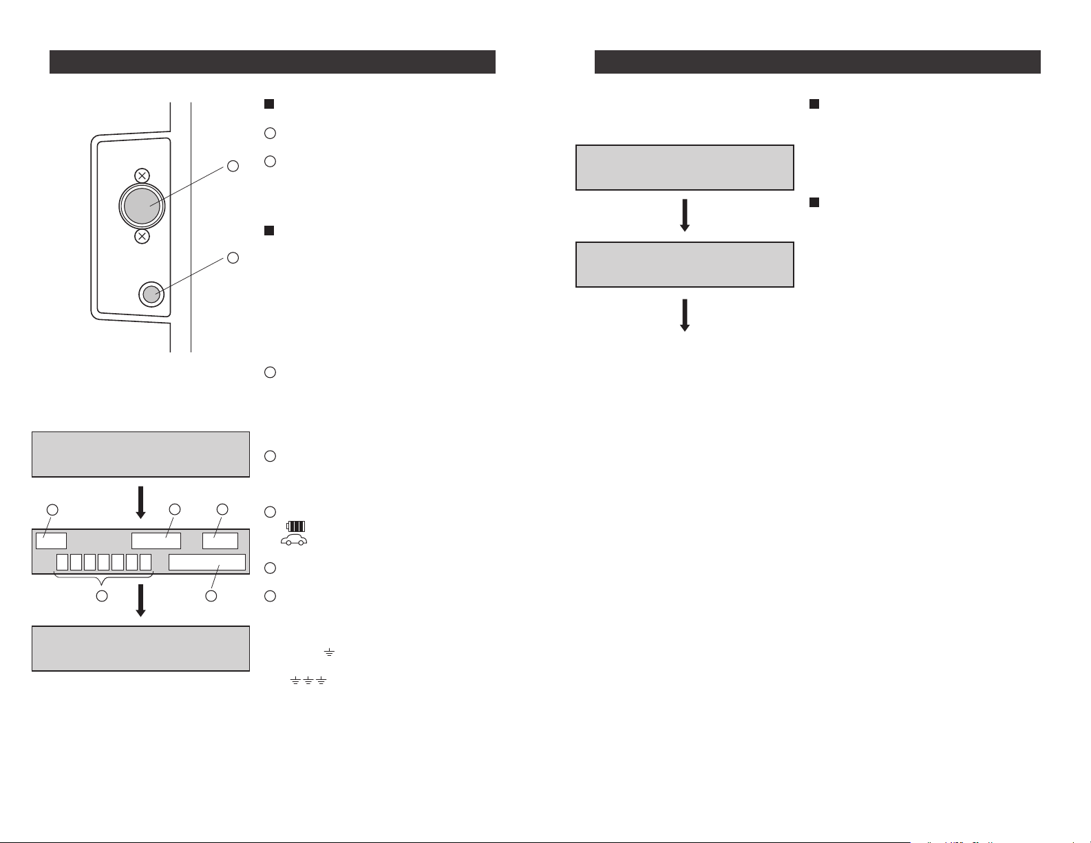
Connections
Direct Mode Connection.
6
External Power Connection.
7
With the optional 12 volts DC power
cables, the Transmitter can be powered
from a truck or a car 12 volts battery.
Transmitter LCD Display
The PL-2000 Transmitter displays the
following information:
To turn the TRANSMITTER ON, push the
Power ON/OFF. The sounds “Tick-Tack” are
repeated four times and indicate that the
Power Switch is ON.
A
Display Frequency:
Inductive Mode : 27kHz or 8kHz.
Direct Mode : 27kHz, 8kHz, 0.5kHz
or MIX. MIX means the simultaneous
output of 27kHz, 8kHz, and 0.5kHz.
B
Output Mode Display:
IND = Inductive Mode
DIR = Direct Connection Mode
Automatic OFF Function
When the TRANSMITTER controls are not
operated in the ON condition for one hour,
the Automatic OFF Function turns OFF the
power.
How to cancel the Automatic
OFF Function
Normally the Automatic OFF Function is activated, but to deactivate this function, push
the Frequency Selection Key and then push
the Power ON/OFF Key.
When the Automatic OFF Function is deactivated, “CONTINUOUS” is displayed on the
Transmitter display.
Note: The transmitter operates in the
Automatic OFF mode every time you
turn it on. If you wish to operate in the
“Continuous” Mode, you must deactivate the Automatic OFF mode each
time after the words “SUBSURFACE
PL-2000” are displayed.
C
Power Source Display:
= D Cell Battery Operation
= Car Battery Operation
D
Display of Output Power from 0 to 7
E
Display of the ground conductivity and
the strength of the current owing in the
Direct Mode.
• POOR means “poor ground
connectivity”
• means “signal level is good”
When the TRANSMITTER controls are not
operated in the ON condition for one hour,
the Automatic OFF Function turns OFF the
power.
Page 7
6
7
Su bS ur f ac e
PIP E L I N E
CABL E L O C AT O R
PL-
2000
KH z S ENS .
A
B
C
D
9
10
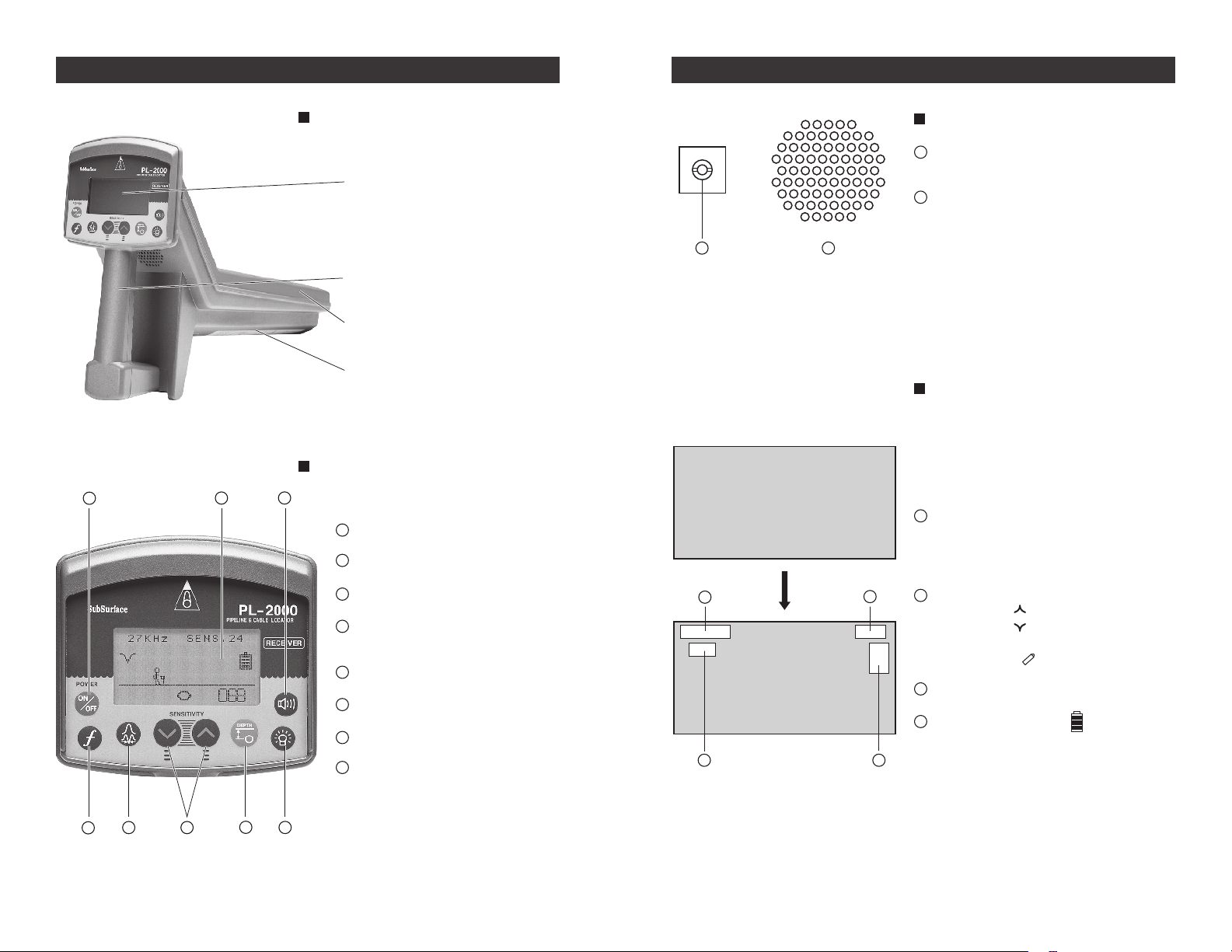
LCD Display
Operation Panel
Handle
Antenna
Battery Compartment
Cover
1
2 3 4 5 6
78
OPERATION OF RECEIVEROPERATION OF RECEIVER
Receiver Unit
Receiver Operation Panel
1
Power ON/OFF Switch
2
Frequency Selection Switch
Back of Receiver
Headphone Jack located on the back of
9
Receiver
10
Speaker located on the back of Receiver
LCD Display of Receiver
The PL-2000 Receiver displays the following
information:
Push the ON/OFF Switch to turn ON and
“SUBSURFACE PL-2000” is displayed.
A
Frequency Display:
27 kHz or 8kHz or 0.5kHz or RADIO or
CABLE. The PL-2000 always “boots”to
27kHz after four “CLICKING” sounds.
Mode Selection Switch
3
Sensitivity Adjustment Increase
4
and Decrease
5
Depth Measurement
6
Back Light Switch
Sound Volume Control
7
8
LCD Display
B
Mode Display:
Peak Mode =
Null Mode =
Long Distance Mode = (DIST)
Sonde Mode =
C
Sensitivity Level ranging from 0 to 40.
D
Battery Power Display.
When the keys are not operated for ve
minutes, the Automatic OFF Function turns
OFF the power to automatically save battery
power.
Page 8

8
9
Left or Right.Pipe.
27 k Hz S E NS. 30
27 k Hz S E NS. 30
Frequency. Sensitivity Level. (00 to 40)
Depth.
NORMALIZED CURRENT MEASUREMENT
(Useful where “ghost” or multiple lines are detected. Highest
current measurement indicates your particular target line.)
Residual Battery Power.
27 k Hz S E NS. 30
Frequency. Sensitivity Level. (00 to 40)
Frequency. Sensitivity Level. (00 to 40)
inch
Numerical Value. (000 to 100) Bar Graph.
Battery Power.
Battery Power.
OPERATION OF RECEIVEROPERATION OF RECEIVER
The PL-2000 Receiver has 4 operating
modes: Peak, Null, DIST, and Sonde.
1. Peak Mode
2. Null Mode
3. DIST Mode
4. Sonde Mode
Four Operating Modes in
Receiver
The “Peak” Mode employs the PL-2000’s
patented differential antenna to produce the most accurate locates. Depth
Measurement (+ or – 5% accuracy) is
available in Peak Mode.
The PL-2000’s “Null” mode is a fast locating tool with “left-right” guidance in a crosssection view of the pipe and the user.
The “DIST” Mode offers even longer
distance locating than the Peak Mode,
as much as 40% – 50% further. Locating
accuracy is less in the DIST Mode, and
Depth Measurement is not available.
The “Sonde” Mode allows the Receiver
to locate sewer Sondes accurately and
measure their depths correctly. Any 512
Hertz Sonde or the SubSurface 8 kHz
Sonde can be used.
Three Active Frequencies and
Two Passive Frequencies
The PL-2000 Receiver has 3 “active”
frequencies, meaning these frequencies
are transmitted by the Transmitter and
matched by the Receiver: 27kHz, 8Hz
and 0.5kHz. Higher frequencies “bleed”
off faster than lower frequencies, and
lower frequences will go longer distances
down the pipes and cables. However,
higher frequencies can be applied more
Continued on page 10
MODE AND FUNCTION DISPLAYS
(Peak Mode, Null Mode, and Depth Measurement Function)
PEAK MODE
Display of Peak Mode
NULL MODE
Display of Null Mode
DEPTH MEASUREMENT
FUNCTION
Display of Depth
Measurement Function
Page 9

10
11
˜
OK
to operate.
Change
batteries.
The residual power is indicated in the LCD.
Transmitter LCD Display
REPLACEMENT OF BATTERIESOPERATION OF RECEIVER
Continued from page 8
easily in the Inductive Mode (Transmitter) than lower frequencies, and the 512
Hz frequency is so low that it can not
be induced at all. The 512 Hz frequency
must be used in the Transmitter’s Direct
Connection Mode only.
“Passive” frequencies are in the Re-
ceiver only, and the Transmitter is not
used. The two “passive” frequencies are
50/60 Hz (current owing A/C) and Radio
(15 kHz – 25 kHz).
How to Read
Current Measurement
The Current Measurement is the normalized
value displayed between 000 and 100
converted from the signal transmitted in the
buried pipeline or cable. The value between
000 and 100 tells the PL-2000 user whether
he/she is locating the primary line or a
secondary conductor. Induced currents on
secondary conductors running parallel and
close to the primary line always have lower
current measurements.
Transmitter Battery Power
When the battery mark displayed in the
LCD is reduced to a blank icon, replace the
batteries.
How to Change the Batteries
Push the Battery Cover in the
direction indicated.
Note: The Current Measurement only
appears in the Depth Measurement
Function of the Peak Mode, and it is
a relative measurement of the current
ow.
The Battery Cover will detach.
Install the 8 “D” cell batteries in the directions shown on the back wall of the battery
compartment. The top row has positive
poles facing right, and the bottom row has
positive poles facing left.
Page 10

12
13
Buried pipeline.
0 = Correct
X = Wrong
1 2
3
(c) (b)
OK to operate.
The residual power is indicated in the LCD.
Receiver LCD Display
Replace
batteries.
˜
HOW TO OPERATE THE TRANSMITTER REPLACEMENT OF BATTERIES
Receiver Battery Power
When the battery mark displayed in the
LCD is reduced to a blank icon, replace the
batteries.
How to Change the Batteries
Push the Battery Cover in the direction indicated by a small Arrow Mark. The Battery
Cover will detach.
Inductive Mode
1. In the Inductive Mode, place the Transmitter in the correct position as shown
below. The Transmitter should face in the
direction of the pipeline. If the Transmitter
is positioned parallel to the pipeline, no
signal will be induced on to the pipeline.
2. Push the Power ON/OFF Switch (1) and
conrm the following:
(a) Check the residual battery power by
the indication of (b).
(b) Conrm the operation mode of IND
(Inductive Mode) (c).
Pull out the Battery Pack and replace all batteries. Install the 6 “AA” cell batteries in the
directions shown on the bottom of the battery pack. Reinstall the battery pack inside
the Receiver with the metal tabs contacting
the battery pack connectors.
Note: When switching ON again soon after
switching OFF, wait for ten seconds
before turning ON to allow the circuits
to de-energize.
3. In the inductive mode, choose the frequency 27 kHz or 8 kHz. 27 kHz is best
for Inductive Mode, and 8 kHz is best for
locating long pipelines.
4. Adjust the power output level:
When the Power ON/OFF Switch is
turned ON, the output level is set near its
maximum. The “L” in the LCD shows the
power output level, rangiing from 0 to 7
bars.
Page 11

14
15
1
3 2
4
MESSAGE DISPLAYED ON THE LCDHOW TO OPERATE THE RECEIVER
How to Operate the Receiver
1. Push the Power ON/OFF Switch (1)
2. Choose one of the following modes at
the Operating Mode Switch (2):
Peak Mode: Used to locate the pipeline
with greatest accuracy.
Null Mode: Faster method for approxi-
mate pipeline location.
Dist Mode: Used to locate the pipeline
over a long distance.
Sonde Mode: Used to locate non-metallic
pipelines such as PVC pipes
and asbestos/cement pipes
with no tracer wire.
3. Choose a frequency (3). Switch the Receiver frequency to the same frequency
as the Transmitter. The sensitivity level
in the Receiver will be automatically set
based upon the strength of the signal
from the transmitter. Adjust the sensitivity
up or down until the signal is shown on
the sides of the pyramid in the display.
4. Adjust the sensitivity (4). If the words
“Excess Sens” appear at the top of the
pyramid, reduce the sensitivity (gain)
using the down arrow key until the signal
re-appears on both sides of the pyramid.
As long as the words “Excess Sens” appear, the user cannot locate the pipeline
position accurately.
If there are no bold bars on the sides of
the pyramid, then increase the sensitivity
using the up arrow key.
If the bold bars are partially up the
pyramid, then the user is locating the line
accurately.
• CHANGE BATT. Indicates time to change the batteries.
• OVER CURRENT Indicates very low resistance to current ow in
• IND. Inductive Mode
• DIR. Direct Mode
• Indicates the use of car battery power.
• POOR Indicates poor ground conductivity or poor current
• Indicates good ground conductivity and good connec-
• CONTINUOUS Indicates the cancellation of the “Automatic OFF”
• POWER OFF Indicates “Power OFF” after non-operation of any con-
2. RECEIVER DISPLAYS
• EXCESS SENS Indicates excess sensitivity. Depress the down arrow
• ERROR DEPTH Indicates the pipeline depth could not be measured.
• ILLEGAL FUNCTION Indicates the depth measurement is not available in
• NO SIGNAL Indicates the signal from the Transmitter is too weak.
• GAIN ERROR Indicates that the input signal to the Receiver is un-
• WAIT “Processing…please wait”
The PL-2000 Transmitter and Receiver display the
following messages on the LCD.
1. TRANSMITTER DISPLAYS
the pipeline in the Direct Mode. The Transmitter automatically adjusts the output power to reduce current.
ow because of a bad connection in the Direct Mode.
tions in the Direct Mode.
function. The Transmitter will operate continuously
until turned OFF or the batteries are dead.
trols for one hour or the Power Switch is turned OFF.
key until the message disappears.
Hold the Receiver still and directly over the line.
this operating mode (Null and DIST).
stable, and the depth cannot be calculated. Increase
the sensitivity at the Receiver or the output power at
the Transmitter.
• POWER OFF Indicates the Power ON/OFF Switch is turned off
• CHANGE BATT. Indicates time to change the batteries.
automatically after non-operation of any controls for
ve minutes.
Page 12

16
17
High sound
070
Low sound
020
Low sound
020
High sound
070
On left side
Pipeline.
Receiver.
Operator's Picture
On left side
On right side
On right side
Low sound.
020
Maximum sound.
080
Low sound.
020
Pipeline.
Receiver.
Directly over
the pipeline.
Bar Graph.
OPERATION IN THE FIELDOPERATION IN THE FIELD
1. PEAK MODE
In the Peak Mode, the pipeline location is
indicated by the “rising pyramid” bar graph,
by the numerical display directly below it,
and an increase in sound output.
The “rising pyramid” bar graph increases
as the Receiver is moved closer to the
pipeline from either side. If there is no “rising
pyramid,” increase the sensitivity using the
Up Arrow key. When the “rising pyramid”
reaches a maximum, the Receiver is directly
over the pipeline.
The numerical display beneath the “rising
pyramid” and the audio sounds are also
indications of the strength of the signal.
Both are also at their maximums when the
Receiver is directly over the pipeline. Often,
small changes in the numbers displayed or
in the audio are easier to detect than small
changes in the height of the pyramid.
2. NULL MODE
a) Hold the Receiver directly over the
pipeline and facing in the direction of
the pipeline. Adjust the sensitivity with
the Sensitivity Up/Down Arrows until the
sensitivity level (upper right corner of
display) is about 30.
b) Adjust the sound level with the Sound
Volume Control Key to a level easily
heard by the user. The sound volume
cycles through 4 levels.
Middle Low Stop High
c) As the Receiver is moved closer to the
pipeline from either side, the sound level
decreases. Directly over the pipeline,
the sound level is at its minimum, and
the small gure jumps from one side of
the pipe to the other very quickly. This
minimum point is the “Null” location.
NOTE: There is no depth measurement
function in the Null Mode.
Page 13

18
19
Move the Transmitter over
the ground surface keeping a space
above the ground of 3 – 4 inches or so.
020
080
5m
020
Right upon
the pipeline.
Max.,Graph and Value.
X
X
X
C
B
A
Move the Transmitter
directly over the pipe.
Look for Maximum
points as X X X.
(+5 to 10ft)
(+5 to 10ft)
(+20 to 25ft)
OPERATION IN THE FIELDOPERATION IN THE FIELD
3. INDUCTIVE MODE
How to set up the Transmitter
In the Inductive Mode the Transmitter delivers the maximum power level to the pipeline
when it is directly over the pipeline and facing in its direction.
1. If the pipeline location is known, set the
Transmitter down directly over it and facing in the direction of the pipeline’s path.
If the location is not known, try to set the
Transmitter near it or ask your assistant
to hold it close to the ground.
2. Choose either the 8 kHz or 27 kHz for
both the Transmitter and Receiver.
3. Set the Receiver’s Operating Mode to
Peak Mode.
4. Set the Transmitter’s output power to its
maximum and the Receiver’s sensitivity
to a high level, such as 30 or 40.
5. With the Receiver, start at a location 2025 feet away from the Transmitter, and
walk in a circle around the Transmitter. If
there is a suspected area for the pipeline,
go there and rotate the Receiver until it
indicates the direction of the pipeline.
Otherwise, circle the Transmitter until the
pipeline is detected. Rotate the Receiver
to determine the direction of the pipeline.
Now, ask your assistant to move the
Transmitter over the pipeline. The Transmitter is directly over the pipeline when
the Receiver’s signal is the strongest.
Finding the Optimum Transmitter
Location with Only One Person
In the Inductive Mode, a single operator can
nd the optimum Transmitter location using
the following procedure.
1. Choose either 8 kHz or 27 kHz for both
the Transmitter and Receiver.
2. Set the Transmitter’s output power to the
maximum and the Receiver’s sensitivity
to a high level, such as 30
or 40.
3. Try to set the Transmitter near the
pipeline, if possible, and facing in the
direction of the path of the pipeline.
4. With the Receiver, start at a location (A)
20-25 feet away from the Transmitter.
When the signal is detected, rotate the
Receiver to determine the direction of
the pipeline and position the Receiver
directly over it. At this spot, place a ag
or make a mark.
5. Move 5-10 feet further away from the
Transmitter to (B), and nd the maximum
Receiver signal by rotating it and moving
it back and forth over the top of the pipe.
Mark the pipeline’s spot again.
6. Move another 5-10 feet away to (C) and
repeat locating the pipeline exactly. Now
the three locations show the exact path
of the line, and the Transmitter should be
moved directly over the line.
Page 14

20
21
Ground Stake.
Black Cable.
Red Cable.
Longer Distance From Line.
27kHz 8kHz
MIX
0.5kHz
2 43
5
(A)(B)
27kHz is chosen automatically
when the Power Switch is turned on.
"Tick" "Tick"
"Tick"
POOR
(B)
(B)
Poor
Ground
Good
Ground
OPERATION IN THE FIELDOPERATION IN THE FIELD
4. DIRECT CONNECTION MODE
The Direct Mode is usually preferred if
the pipeline or a tting, like a hydrant, is
exposed.
1. Plug the Direct Connection Mode cables
into the Transmitter at the connector on
its side. Connect the clamp of the red
cable to the pipeline at a hydrant bolt, and
connect the black cable to the ground
stake, Locate the ground stake adjacent
to the pipeline, 10-15 feet away.
2. Set the output mode at DIR for Direct Mode.
3. Choose a frequency from among the four
available 27kHz, 8kHz, .5kHz, or “Mix”
(all 3), using these considerations.
• For water pipelines and other
gasketed pipes, choose 27 kHz or
8 kHz. In different systems, one frequency will be better than the other.
• For continuous conductors like cop-
per service lines and steel gas lines,
choose .5 kHz.
• For certain conductors, choose “Mix.”
4. Set up the Power Output Level with the
up/down arrow keys.
5. Check the Transmitter display for good
ground conductivity and good clamp connections on the red cable and the black
cable. If 2 or 3 “ground symbols”
are shown, the current transmitted to the
line is good. If “poor ground” is displayed,
improve the clamp contact at the red
cable or move the black cable and ground
stake to a new location.
Finding the Optimum
Transmitter Location
In the Direct Mode, the location of the
ground stake can be critical to locating the
line accurately.
1. The ground stake should be located to
the side of the pipeline and as far away
from it as possible in order to maximize
the current ow in the line. The ground
stake should not be located past the end
of the line or close to an elbow. If these
are nearby, move the ground stake in the
opposite direction, away from them.
2. Check for multiple lines by moving the
Receiver across the entire area between
the ground stake and the red cable’s
clamp connection to the pipeline. If a
second or third line is detected in the
“straddle area,” move the ground stake to
the opposite side of the primary line to be
located.
3. If multiple lines are present, use as low a
frequency as possible, such as 8 kHz or
.5 kHz, to minimize or eliminate “jumping”
to other conductive lines.
Page 15

22
23
Black Cable.
Cable Drum.
Red Cable.
Fitting 1. Fitting 2.
Pipeline.
Transmitter.
Inductive Clamp.
OPERATION IN THE FIELDOPERATION IN THE FIELD
5. LOOP MODE
NOTE: The Loop Mode requires the optional
Cable Drum with 50 meter cable, or
make up your own length of wire cable.
The Loop Mode (or method) is often useful
for locating water mains and service lines
in areas with congested utilities. The Transmitter is operated in the Direct Connection
Mode, and cables are used to directly connect the positive and negative leads from
the Transmitter to the ttings that bracket
the line to be located.
1. Look for two ttings/connections to the
system that bracket the line to be located.
Service line meters, hydrants, and valves
are all suitable in water distribution
systems, but the pipes must all be metal
(and not plastic).
2. Connect the positive lead (red) cable down
to the further-most tting and the negative
lead (black) cable to a nearby tting.
3. Set the Transmitter to 8 kHz (or .5 kHz
for completely continuous conductors) to
minimize signal “jumping.”
4. Locate the buried pipeline with the Receiver
between the two ttings (1) and (2).
NOTE: Any pipelines beyond the ttings will
not be located by use of the Loop
Mode. The signal only ows between
the two ttings.
INDUCTIVE CLAMP MODE
1. The Inductive Clamp Mode is used to
energize insulated wires such as telephone lines and low power electric lines.
The Transmitter is operated in the Direct
Mode, and the cables for the Inductive
Clamp must be plugged into the connector on the side of the Transmitter.
2. Open the jaws of the Inductive Clamp
and close them around the insulated
cable. The ground shield for the cable
should be attached to ground at the opposite end of the line to be traced. Switch
the Transmitter and Receiver to 27 kHz
to induce the strongest signal in the insulated line.
NOTE: The Inductive Clamp Mode requires
the optional Inductive Clamp as
shown above.
NOTE: When the Inductive Clamp is
clamped around a power cable,
wear Rubber Gloves as a safety
precaution to avoid electric shock.
Page 16

24
25
2 3 4
1
Power Transmission Lines.
Radio Station.
PL-2000 Receiver.
RADIO
LED
OFF
ON
8 kHz Sonde.
Detectable
Depth:
15 feet.
OPERATION IN THE FIELDOPERATION IN THE FIELD
7. RADIO MODE
The passive Radio Mode employs only the
PL-2000 Receiver and the ambient radio
signals emanating from power lines, radio
stations, and other low frequency radio
communications. These radio signals are
present all over the earth and they often
energize long pipelines, such as water and
gas lines.
1. Press the Frequency Select key (2) until
“Radio” is displayed on the receiver’s
screen.
8. SONDE MODE
The Sonde Mode is useful for locating nonmetallic pipelines, like PVC or asbestos/cement sewer pipes, clay pipes, concrete, etc.,
that do not have a “tracer wire.” A “Sonde” is
a small battery powered transmitter that can
be attached to a sewer “snake,” other exible rod, or a “PIG,” and pushed, or ushed
through the pipe with a string attached to it.
Check the particular Sonde and PL-2000
Receiver together rst outside of the pipe
on the ground. Conrm that the Receiver
is detecting the Sonde and measuring its
depth correctly.
1. Turn ON the PL-2000 Receiver and
press the Operating Mode key until a
small Sonde appears in the upper left
corner of the display.
2. At the Frequency Selection Key, choose
27 kHz, 8 kHz, or a .5 kHz, depending
upon the frequency transmitted by the
Sonde.
3. Turn ON the Sonde and lay it on its
side. The PL-2000 receiver detects the
Sonde from the side of the Sonde. When
the Sonde moves through the pipe, the
receiver is faced parallel to the pipe (and
the Sonde) and not in the direction of the
pipe (90 degrees from normal operation).
2. At the Operating Mode key (3), choose
the “Peak” Mode. The Radio Mode only
works with “Peak” Mode.
3. Increase or decrease the Sensitivity (4)
with the up/down arrow keys until the
“signal pyramid” appears as two bars on
the pyramid sides.
NOTE: The DEPTH function is not available
in Radio Mode.
4. A Sonde makes 3 peaks: A large one
directly over it and two “false” peaks, one
off each end of the Sonde.
Page 17

26
27
27 kH z SE NS .3 0
inch
Depth. Current Measure.
(000 - 100)
(D)
PIPELINE & CABLE LOCATOR
SENSITIVITY
RECEIVER
ON
OFF
POWER
DEPTH
PL-2000
PIPELINE & CABLE LOCATOR
SENSITIVITY
RECEIVER
PLー960
ON
OFF
POWER
DEPTH
(A)
(C)
(B)
CA BL E SE NS .3 0
CA BL E SE NS .3 0
Display of Peak Mode
Display of DIST Mode
DIST
OPERATION IN THE FIELD
OPERATION IN THE FIELD
9. LIVE CABLE MODE
The Live Cable Mode is useful for scanning
a job site for buried, live power cables with
50/60 Hz AC current owing. The AC current
must be owing and not just be “potential”
current. (The Power Line must be “USING”
substantial current.)
1. At the Frequency Selection key, choose
“Cable.” At the Operating Mode Selection key, choose either “Peak” or “DIST.”
In the “DIST” mode the distance located
is greater but the locating accuracy is
reduced. Adjust the sensitivity to the
maximum with the UP arrow key
(to level 40).
2. Use the PL-2000 Receiver to scan for
the presence of live cables. When a live
cable is detected, it can be traced with
the Transmitter in the Inductive Mode
and the Receiver switched to the matching frequency 27 kHz or 8 kHz.
3. In the Live Cable Mode, the PL-2000
Receiver’s depth function is not available, and the Transmitter is not used.
Depth Measurement in Peak and
Sonde Modes
The Depth Measurement function is available in the Peak and Sonde Modes, and is
nominally accurate to +/- 5%. Like all pipe
and cable locators, there must be at least
70 feet between the Receiver and Transmitter in order for the Depth Measurement to
be accurate, and there must be only one
conductor.
1. For Depth Measurement of a pipe or
cable, select “Peak” at the Operating
Mode key. Locate the line exactly over
the top of it with the PL-2000 Receiver,
and rest the rubber “foot” of the Receiver
on the ground or street (see A).
2. Rotate the Receiver until it is directly
facing in the direction of the line and the
signal is the strongest (see B).
3. Depress the “Depth” key and hold the
Receiver still for a few moments until the
depth is displayed in inches (see C).
4. In the lower right corner of the depth
display is the Current Measurement normalized between 0 and 100. If multiple
lines are present, the primary line has the
highest current.
5. If the message TX POWER DOWN appears on the Receiver, reduce the output
power of the Transmitter.
Page 18

28
29
030
010
080
Figure 1.
2m
AB
A
B
B
A
Figure 2.
Transmitter.
27kH z SEN S . 3 0
inch
27kH z S ENS.3 0
inch
Direct Connection Mode.
Ground Stake.
Current
Measure
of the pipe (1).
Current Measure of the pipe (2).
Pipe (1)
Pipe (2)
APPLICATIONSOPERATION IN THE FIELD
Current Measurement in Parallel
Lines
If two lines are within 2-4 feet of each other
and parallel to each other for at least 50 feet
or more, the primary line may induce a signal
in the secondary line, particularly at higher
frequencies (27 kHz).
The secondary line always has lower current
ow than the primary line, which should be
energized by the Direct Mode at the Transmitter to minimize “jumping.”
How to Locate Parallel Pipes
by Inductive Mode.
NOTE: When parallel pipelines are de-
tected, the Direct Mode should be
utilized when possible.
As shown in the above Figure 1, the Maximum Bar Graph and Maximum Numerical
Value are continued between the points (A)
and (B). In this case, the two pipelines (A) and
(B) must be located separately.
1. Set up the Transmitter at the outside of
the pipeline (A) keeping the distance of 2
meters or so to the pipeline (A) as shown
by the above gure.
1. Locate both lines exactly with the PL-2000
Receiver and press the Depth key with the
Receiver directly over each line. Note the
Current Measurement for each line.
2. The line with the larger Current Measurement value (0-100) is the primary line
attached to the positive (red) Direct
Connection cable from the Transmitter.
3. The ground stake should be moved as far
away from the secondary line as possible.
If the ground stake crosses over the secondary line, both lines may have the same
(or similar) Current Measurements.
2. Move the Receiver from the outside of the
pipeline (A) toward the pipeline (B). The
Bar Graph and the Numerical Vale will be
changed as in the above example. The
point of the Maximum Bar Graph and the
Maximum Numerical Value of 080 is the
location of the pipeline (A).
3. When the pipeline (B) is located, move the
Transmitter to the outside of the pipeline (B).
NOTE: In cases where there are more than
two parallel pipelines in a short
interval, the Inductive Mode can
locate only the two pipelines on the
outsides.
Page 19

30
31
030
030
080
Ground Stake.
APPLICATIONSAPPLICATIONS
030
030
080
Main Pipeline.
Ground Stake.
Branch Pipeline.
Locating Congested Utilities with
the Direct Mode
The Direct Mode in the Transmitter together
with the lowest frequency are the best
strategy for locating lines in areas with congested utilities.
1. Select the Direct Mode in the PL-2000
Transmitter and choose either the 8
kHz or .5 kHz frequency. If the primary
conductor to be located is continuous,
like a steel gas line or a tracer wire,
then choose the .5 kHz frequency. If the
primary target is a water main, choose
8 kHz. For an insulated tracer wire,
remember to ground the far end.
2. Connect the positive (red) cable to a
metal tting connection or valve in the
target line. Position the ground stake for
the negative (black) cable very close or
directly over the top of the target line.
This minimizes energizing the adjacent
lines.
3. Because the ground stake is so close to
the target line, the distance located will
be relatively short.
Locating Branches in Pipelines
and Water Services from the Main
Locating branches in pipelines and service
lines from water mains can be done in the
Direct Mode or the Inductive Mode, but
usually the Direct Mode is preferred. In the
Direct Mode at 8 kHz, the PL-2000 Transmitter has maximum power.
1. In the Direct Mode, select a location for
the ground stake that is on the same side
of the main as the branch pipeline or service line. Put the stake 10-15 feet away
from the main to maximize the power
delivered to both.
2. Use “Peak” Operating Mode to have the
greatest accuracy for locating the branch
line or service line.
3. Walk parallel to the water main 5-10
feet away from it in the area where the
branch pipeline or service line is expected to be. Hold the PL-2000 Receiver
parallel to the main and facing in the
direction of the branch or service line.
When the Receiver crosses over the line,
it should respond immediately.
Page 20

WARRANTY
Warranty
SubSurface Locators and SubSurface
Instruments, Inc. (SubSurface) warrants the
PL-2000 and all of its accessories to be free
from defects in material and/or workmanship
for a period of thirty-six (36) months from the
date of shipment by SubSurface to the original
purchaser, subject to the following:
SubSurface’s warranty obligation is, in its sole
discretion, strictly and absolutely limited to
repair or replacement of any product or part
thereof. Any product for which a warranty claim
is made must, as a condition precedent to warranty coverage, be returned to the factory, shipment prepaid, by the original purchaser and
must be accompanied by a written explanation
of the defect in material and/or workmanship.
Additionally, and as a further condition precedent to warranty coverage, all serial numbers
must be legible and all components of the
product must be intact and not dis-assembled
or opened by un-authorized repair individuals.
All other warranties, express or implied, including, but not limited to, any implied warranty of
tness for a particular purpose and any implied
warranty of merchantability are specically
disclaimed. Specically, and without limita-
tion, damage to the product caused by abuse
or misuse of the product, exposure of the
product to or contact with battery acid, any
caustic substance or water are specically
excluded from the warranty hereunder. Under
no circumstance shall SubSurface be liable
or responsible for any injury to any persons or
any property or for any special, consequential,
incidental, punitive or other damages of any
kind whatsoever incurred by reason of the purchase or use of this SubSurface product. The
Purchaser agrees, by accepting delivery, that
it will forever keep, save and hold SubSurface
and its ofcers, directors, employees, agents,
parents, subsidiaries and afliates, completely
free and harmless from and against any and
all such damages and any and all such costs,
including, but not limited to, attorney’s fees and
legal costs arising therefrom.
32
Page 21

PL-2000
Operation Manual
SubSurface Instruments, Inc.
1230 Flightway Drive
De Pere, WI 54115
Phone: (920) 347-1788
FAX: (920) 347-1791
Web: www.ssilocators.com
 Loading...