

Page 1

SubSurface Instruments Inc.
1841-C Plane Park Drive
De Pere, WI 54115
“AML”
is a Trademark of SubSurface Instruments
(Patents Pending)
All Material
Locator (AML)
Operator’s
Manual
920-347-1788 Phone
920-347-1791 Fax
info@SSILocators.com
www.SSILocators.com
Made
In the
U S A
Page 2

Table of Contents
2 Table of Contents
3 FCC/IC Statements
4Overview
5 Parts
6 Operating Panel & Battery Replacement
7 How it Works
8 Alignment of Signal
9 Technology Overview
10 Search Method
11 About Pipes & Cables
12 About Other Objects
13 About Depth Estimating
14 Depth Estimation via Triangulation
15 Warranty Statement
PAGE DESCRIPTION
2
Page 3

FCC/IC Statements
•FCC
This equipment has been tested and found to comply with the limits for a Class A digital
device, pursuant to Part 15 of the FCC rules. These limits are designed to provide
reasonable protection against harmful interference when the equipment is operated in
a commercial environment. This equipment generates, uses, and can radiate radio
frequency energy and, if not installed and used in accordance with the instruction
manual, may cause harmful interference to radio communications. Operation of this
equipment in a residential area is likely to cause harmful interference in which case
the user will be required to correct the interference at his own expense.
• IC (Industrie Canada)
Operation is subject to the following two conditions:
(1) This device may not cause interference, and
(2) This device must accept any interference, including interference that may cause
undesired operation of the device.
3
Page 4

“AML” ™
“Think, Point, and Shoot”
• One hand operation.
• No separate transmitter/receiver.
• No wires, no stakes, no clips or clamps.
• Metallic and/or Non-Metallic targets.
• On/Off “Point & Shoot”.
• 3 Sensitivity Settings: Hi, Med, Low.
• 4 Alkaline “C” cells.
• Weight 2.5 # with batteries.
• Laser light marks the “spot”.
Just imagine where the target
is, and “point it out”. Think,
scan, use common sense… find
and confirm the target.
4
Page 5
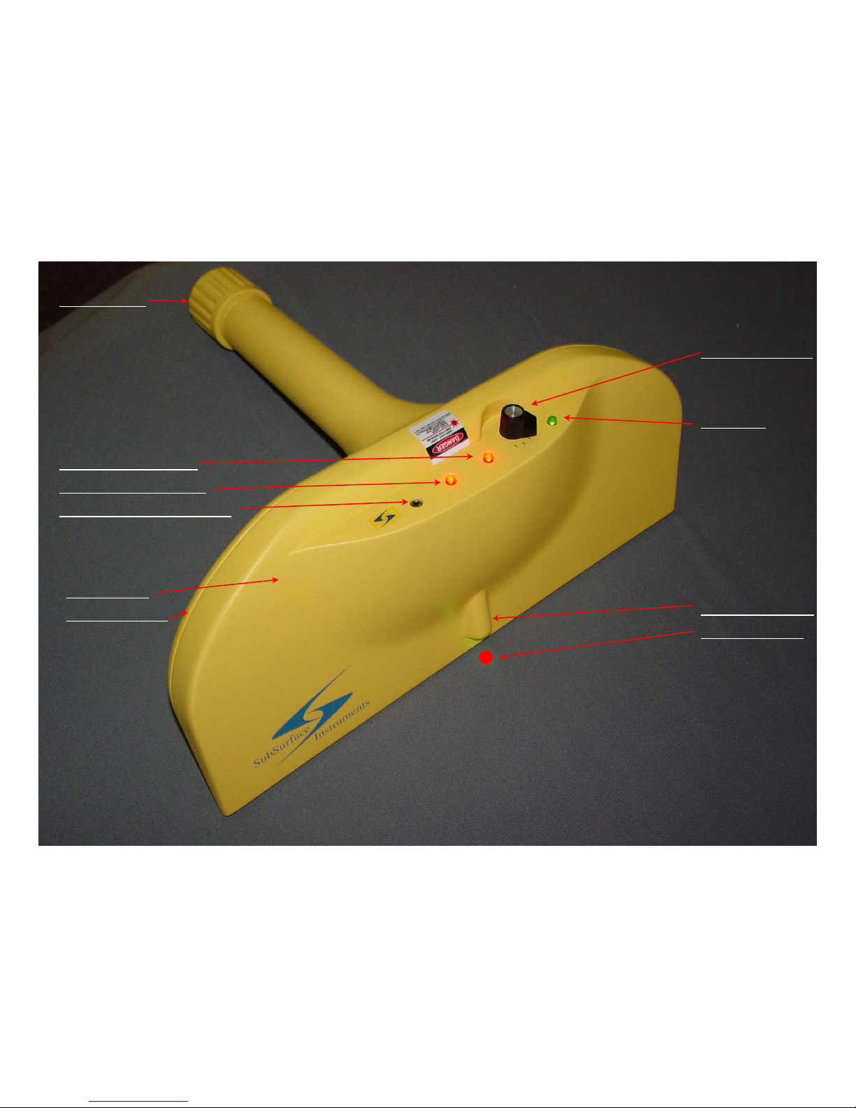
Name the Parts
Battery Access
Screw Off & On
Flashlight-type access:
4 “C” cells recommended.
(Insert “+” end of battery first)
Left side target indicator
Right side target indicator
Test/Tuning Access (covered)
On/Off Knob 4-pos:
Off, and…
3-high, 2-med, 1-lo
w
Green LED
(Indicates unit “ON”
)
Target Laser Cavity
RED Laser marks
the Target Position.
WARNING – DANGER
NEVER point the front of this unit (which contains the “Laser”) in
such a direction that it may cause eye injury to yourself or anyone
else. This Positioning RED Laser can & will come on (activate
automatically) at any moment when the unit is turned ON, even if
you cannot see it; therefore, heed the WARNING at all times.
Handle
T
o
p
Ba
c
k
Fr
o
n
t
Cap
Right Side
Left Side
Clamshell Top
Clamshell Bottom
5
Page 6

Operating Panel & Battery Replacement
Green LED indicates when unit is “ON”
Pointed Knob
is “OFF” in left position,
“ON” in High #3 Sensitivity
“ON” in Med #2 Sensitivity
“ON” in Low #1 Sensitivity
Left Target Indicator:
When the Left Target Indicator “flashes”, it has detected the
vicinity of a possible target. When it becomes “solid” it has a
possible target.
Right Target Indicator:
When the Right Target Indicator “flashes”, it has detected the
Vicinity of a possible target. When it becomes “solid” it has a
possible target.
Left & Right Target Indicators:
When BOTH Left & Right Target Indicators become solid at
the same time, the unit has detected a Target. AT THAT
MOMENT:
The RED Target Position Laser
comes on automatically (not
shown in this photo), and indicates a RED spot on the surface
that is in a direct line to the target.
WARNING – DANGER Please Read Label
DO NOT ALLOW eye contact (yourself or anyone else)
This Laser can & will come on (activate automatically)
whether it can be seen or not, whenever the unit is “ON”.
DO NOT OPEN
, or attempt to open, the Clamshell top
and bottom halves. There are NO user-serviceable
parts inside; AND, the alignment of the
transmitter/receivers will be adversely affected, as
there are molded bosses, shelves, slots, and attach
points for the antennas and electronic components
built into the insides of the clamshells and upper
handle. If this occurs the warranty is automatically
VOID, and factory service is mandatory AT THE
USER’S EXPENSE.
BATTERY REPLACEMENT:
The unit uses just 4 “C” cell batteries. We recommend
alkaline for longer life.
TO CHANGE THE BATTERIES:
1. Unscrew the Battery Cap at the bottom of the handle.
2. Remove & properly discard the old batteries, if any.
3. Insert the new batteries (4), all in the same direction,
into the bottom of the handle, POSITIIVE “+” END
first, one behind the other.
4. Carefully replace the screw cap.
Handle Grip Area
CAUTION: Do not cross-thread or over-tighten the Battery Cap.
6
Page 7

How it works:
A simple
illustration.
Å
-
-
-
-
-
-
-
-
-
-
-
-
-
-
-
-
-
-
-
-
-
1
0
t
o
1
2
f
e
e
t
o
r
m
o
r
e
-
-
-
-
-
-
-
-
-
-
-
-
-
-
-
-
-
Æ
(
I
n
a
d
i
r
e
c
t
l
i
n
e
w
i
t
h
t
h
e
a
i
m
o
f
t
h
e
l
o
c
a
t
o
r
.
)
Not drawn to scale – used for illustration only…
Å-------------------------------------Beam the width of the locator, at the Front edge.-------------------------------------Æ
Extremely high frequency signals are
transmitted and received in line with
the front edge of the instrument. This
return signal is processed on board
and is reported to the flashing, then
becoming steady, Red LEDs.
When both Red LEDs “LOCK” onto a
target at the same time, a RED Laser
Pointer automatically spots the target
on the surface, IN A DIRECT LINE to
the target at the angle at which you
have detected the target (object).
NOTE: If one Red LED locks onto a
target and the other does not, but you
feel the target should be there, try
twisting your wrist around the axis of
the LED which is locked onto the
target/object. This is done in an
effort to “Line up” the front edge of
the unit (thus the other LED) with the
target… when the second Red LED
locks on, you have then locked onto
a target or object and direction.
Automatic
Laser
Pointer
7
On/Off Sensitivity:
(Pointed Black Knob)
Off: Far left position.
On: 3-High
On: 2-Medium
On: 1-Low
This is NOT Radar
Page 8

The Alignment of Signal to Target
Provides the “lay” or “direction” of the target:
Target Line
Horizontal plane with Laser in Front
Center.
The Target line or edge of an object
must align parallel with the Horizontal
Plane of the locator, for the locator to
“lock onto” the target edge. This
provides “direction” of the target edge.
If one Red LED is solid the locator is
not ‘parallel” with the target, OR, there
may be a false target.
Rotate the locator with wrist action
around the axis of the Red LED that is
solid, to attempt to “line the locator up”
with the target.
Hard to Show in a picture:
When the Red LEDs indicate
that a target has been “locked”
onto, and the automatic RED
“Position” Laser activates, it will
appear in a “Direct Line” looking
right across the top of the
locator like aiming a pistol. It is
also the direct line angle to the
target.
8
Please Notice: The “hand” is
not “high up” on the handle,
nor any other object near the
“head” of the locator/detector.
Page 9

Technology Overview
This is not “GPR” (Ground Penetrating Radar), although mu ltiple signals are sent/received and processed. The technology is
proprietary, and patents are pending. “AML” is also Trademarked. So we are not going to talk about the technology, itself. This
is a single handheld unit that weights about 2.5 pounds, and is simple and easy to use… it just takes patience and common
sense. The locator cannot “tell you” what the target is; that’s up to you. It simply tells you a target has been located.
The great thing is this locator finds just about everything. That means it finds about everything you can find with current
technology magnetic, metal detector, radio frequency, and GPR locators; AND about everything else that they CAN’T find. You
just have to know, or figure out, what you are “on”. You can test the unit with the same type target you will be searching for
underground if you find the target in an open or partially filled trench, but completely buried is best. With the knowledge and
understanding that one must go slowly and use common sense; one should understand that this is a great tool. The locator
loves “edges” of objects.. That means that you can transition from known pipe locations of metallic pipe/cable, or have properly
installed tracer wire; right onto those sections that turn into non-metallic pipe, or the tracer wire is not installed properly, or has
corroded over time. Let’s explore further:
If you use the “AML” to find those things that you know are “…somewhere over here. …run through somewhere along there… I
know it’s down here somewhere, but I just can’t find it with my other locators.” You can see how valuable it is. You may not
have been able to find these items at all before now, unless you hit one. What a difference that makes! And, that’s just pipes &
cables… what about all the other markets… use your imagination… the possibilities are nearly endless. However, the
responsibility of locating/detecting, safety, and confirming the target, as always, still lies with the Operator. Like any “tool” the
more you use it, the better you get. As you can imagine, however, a trench with lots items in it close together will be near
impossible to pick out (follow) one single target.
There have been many cases during testing and demos, where we found the target in a matter of seconds. There is NO setup,
NO plugging in cables, NO installing ground stakes, NO trying to run a “snake”, “fiche”, or “sonde” up a non-metallic pipe to then
hook onto, and still not work part of the time. NO “squiggly” lines to try to interpret. NO need to be an engineer to operate it.
Pull it out, turn it on, and start detecting. One word of caution: There is no way to make this unit impervious to physical abuse;
you must protect the unit against physical shock. Working in rain may be a problem; if it’s uncomfortable for you, it will be so for
the unit. Like a horse, “don’t put it away wet”; let it dry off before putting it back in the case. But, DO NOT THROW this un
it
anywhere; not even in the case. It is a scientific instrument, treat it as such… take care of it, and it will take care of you.
9
Page 10

Searching for Pipes & Cables – Scan & Step
• (We’ve located pipes & cable in a matter of seconds using this
method.) Walk up fairly close to the area where the pipes or
cables are thought to be, and...
• Turn on the “AML”. Stand still and point it across to the other side
of the area… Scan a 6’ swath or less, at a time., even 2 to 4’ is
better. (Pretend you are “slicing the earth” in front of you,
attempting to “slice” the pipe, cable, or object in two.)
• Bring the “AML” slowly down through the area from that point of
beginning, to near your feet… being careful not to get too close to
your feet, or you’ll “locate” them, as well.
• NOTE PHOTO AT RIGHT: When the two “RED indicator LED’s”
are lit up at the same time, it is a “hit”; the locator has detected an
object. Continue through the “swath” and mark or remember each
“hit”, then:
• You MUST “confirm” that you ARE on your DESIRED valid target,
take a couple steps to your right or left, or both, and repeat the
scan; and mark the “hits”. Do the hits “line up”? Is this
reasonable? If you need to pinpoint exactly where the target is,
then move to your mark or past it, and hold the AML vertically
(pointed directly at the ground)… move it slowly to find the “hit”.
When detecting, move the unit, not your feet.
• NOTE PHOTO AT RIGHT: The orange spots are marks where we
had “hits”… (There were two more marks to the left that are out of
this picture.) In this “trial” we detected two non-metallic natural
gas lines, 18” apart, parallel to and 3 feet from a third gas line
marked by the required “utility marking service”… these adjacent
two lines could not have been detected with “RF” locators.
• If the pipe or cable turns, make your scans closer together; and/or
scan at varying degrees to the line… 20, 45, 90, etc. It is
“possible” to “scan” down the line but must be done slowly &
carefully. It’s just a lot easier to “scan & step” sideways.
RED Laser Pointer comes on, and points to a spot on the ground, when a
target has been detected.
10
Å
-
-
-
-
-
-
P
i
p
e
D
i
r
e
c
t
i
o
n
-
-
-
-
Æ
.
.
.
.
.
.
.
.
.
.
.
.
.
.
.
.
.
.
.
.
The
Front
Edge
of the
Locator:
When “locked on” th e
target, indicates the lay
of target.
Page 11

About Pipes & Cables
• The “AML” MAY detect the edge–middle–edge of a shallow pipe, or a large pipe, as you “slice” through the
cross-section. If it is a non-metallic pipe with a tracer wire, you may detect the edge-middle-edge-wire or
wire-edge-middle-edge… depending on which side of the pipe the wire is on, in the trench; unless the wire is
in direct line with the edge or middle of the pipe. …as show below:
Pipe
w/Cable
End View
<Cable
“hit” “hit” “hit” “hit”
If Searching Vertically as in Pinpointing:
If Searching at an angle:
“hit”
“hit”
“hit”
While we’ve found the “scan & step” method to be the quickest in most cases; if the pipe is large enough, one may be able to trace
slowly along the pipe similar to the method of using an “RF” locator, if one moves slowly, and keeps the unit steadily “on” the pipe
while holding the unit in the vertical position only… do NOT swing back and forth like an “RF” locator. In such a case, one would
detect only the “center hit”, unless the pipe is very large. One reason we don’t use the walk-in-line method is it is hard not to detect
your feet or shoes when walking and holding the unit vertical.
You MAY be able to “test” the AML on pipes & cables lying on top of the ground or in an open trench so that you can see exactly
how it locates… Keep in mind that it “loves” edges: that is, the sides and top of a round pipe, again depending on size… thus a
small cable or pipe, or a deep one, would only produce one “hit”, on the rounded side that is directly in line with the unit.
Pipe & Cable cross section on the right
shown “oblong” on purpose. The unit will
detect the “edges” it “sees” in a direct line
from/to the unit. If the pipe at the right
were perfectly round, the hits may be
exactly the same distance from the side
as they were from the top. Notice also
that the cable is in the path of the bottom
edge of the pipe, so only three “hits”
would be seen in the case from the right.
11
NOTE: It may not always be possible to detect the
target at 45-degrees due to distance caused by depth.
Page 12

Some Other Objects:
-Key Point to Remember from the last slide – The AML “loves edges” –
-That could be the center “edge”, the side edges, or all three-
-The composition of the object does not matter –
Septic Tanks, Boxes, and all types of buried Drums: Imagine the edges of the tank, box, or drum, and align yourself to
point the locator in such a manner as to detect the edges as previously discussed. By walking around the tank and taking
scans (slicing the tank in two), one can define the outline of the tank. Remember also, that “rounded edges” like a round pipe
will be defined as an edge. The flat surface of the side or top may be detected if the locator is pointing directly at the flat
surface. If the tank has one or more “clean-out lids” on the top, the edges of that lid may also be detected. If one is careful,
one may be able to keep the locator on a detected edge and slide carefully along the edge to outline it, until it turns a corner.
The drain-field pipes are also detectable by the “scan & step” method.
Graves/vaults/Skeletons: Coffins & vaults would be detected as described above. A buried body or skeleton would be
detected by “hits” on the individual larger bones, and multiple hits on groups of smaller bones.
Buried Walls & Old Foundations: May be detected by the edges of the wall or foundation by the same “scan & step” method.
Storm Sewers and other concrete pipe, or pipe-like structures: would be detected like any other pipe, just remember the
estimated size of such a pipe, it’s shape, and any joining structures; in order to imagine where “edges” would be formed.
Rebar in Concrete, Hot Water Pipes in Concrete Floors: Rebar can be detected in concrete by the same method as
detecting pipe in the ground. One may also be able to “slide” along a piece of rebar once detected if very careful. To detect a
pipe or cable under a concrete floor with rebar in the concrete, is slow and tedious, may be done, but is very time consuming.
One may identify the rebar and then the pipe that runs at an angle to the rebar, and/or between the rebar at other than a normal
distance between the bars… but is very tedious, and may just be too difficult. If the concrete is reinforced with fiberglass
particles instead of rebar, detecting a pipe or cable in it becomes easy, because the reinforcement would not be detected.
Think about it… since the AML finds just about everything, it will also find things like tree roots and other things that could
have been “thrown” in the ground and covered up at construction sites… thus the need to always “verify” your locate.
12
Page 13

About Depth & Depth Estimating
“Triangulation”
• This model is not capable of push-button depth – so triangulation may be used on some
targets. (*See next page for additional information on “triangulation”.)
• Use the appropriate method, previously discussed, to find the target while holding the locator
at a 45 degree angle; and note/mark the spot of the laser point on the ground.
• Go to where you think the target would be directly below, based on the angle at the time of
detection; and detect the target with the locator in the vertical position. This is “pinpointing”
directly over the target. (Be careful to avoid detecting one’s own feet.) Mark the spot of the
laser point on the ground.
• The distance between the two marked spots is the estimated depth of the target. *
• Remember, that is the depth from the surface to the “detected edge” of the target. If it is a
shallow or very large pipe, I’d want to do the depth to the center mark (center edge). *
• 10 to 12 feet is the depth that the AML has been repeatedly tested.
Objects have been
found up to 20 feet deep, but they were large and the edges were not precise.
*Regardless, depth by any method, by any locating instrument, should always be considered to be an
“estimate”… BE AWARE that “Triangulation” may NOT be possible, due to the distance necessary to
make the detection at distance from a 45-degree angle. Deeper targets may make it impossible to do
Triangulation because of the greater distance to the target at 45 degrees.
13
Page 14

- Depth Estimate via Triangulation – True of any locator using this method -
Buried
Target
Pipe
Ground Level
Laser
Pointer
Line
Laser
Pointer
Line
“AML” held Vertical
Pinpoint position
“AML” held
At 45 degree angle
Marked Laser SpotMarked Laser Spot
Distance between “spots” is the depth*
NOT Drawn to Scale!
The triangle on the right, if drawn to scale,
would have vertical and horizontal sides
“equal” -- The depth equals the distance
between the two “marked spots”, as long
as the “laser pointer line” is at a 45
degree angle… depending on the
diameter of the target.
Now, notice the triangle at the left does not
completely reach to a “point” at the bottom,
the two sides do not “join” at the bottom.
The vertical side comes off the closest
point: the top of the pipe. The 45 degree
angle comes off the closest point of the
angle in that direction, so the sides do not
meet.
So. If the target were a “wire”, the distance
would be extremely accurate. If the target is
a 48” diameter pipe, the measurement
would be off 2 feet… The top of the pipe
would be 2’ higher than the measured
distance, because the sides of the triangle
come to a point in the center of the pipe.
So: KNOW YOUR TARGET!
(We’re picking the center
detectable “edge” of the
target for this example –
not the outside edges.)
14
*unless the target is not of a small diameter. See the bottom of the corner of the triangle
above as it (hidden) meets at the center of the target… so it will be “shallower” then the
distance between the “spots”, or about ½ the diameter of the target.
Page 15

Warranty Statement
Warranty Period: 12 Months from original user’s purchase. Save your Receipt.
As always, the responsibility, reliability, and operator/bystander safety, of/while finding/locating and confirming a target, lies with the Operator.
Not responsible for errors and/or omissions in this manual.
15
The “AML” models of SubSurface All Materials Locators are specifically guaranteed to be free of defects in material and workmanship for a
period of 12 months (1) year; to the original end-user purchaser.
Physical abuse, battery acid and water damage; as determined at the sole discretion of SubSurface Instruments Inc., are explicitly and
entirely excluded from this warranty. (Additionally, this is a scientifi c instrument and cannot be protected by the manufacturer from
damage if dropped or placed in an environment which will cause physical or chemical harm to the unit; therefore this shall be considered
abuse, also.)
SubSurface Instruments Inc., its owners, employees, dealers, distributors, and/or assigns, shall not be liable for any action, inaction, injury,
or property damage, sustained or expenses incurred, whether consequential or inconsequential; from the use/non use, misuse, improper or
proper use of this or any product designed, ma nufactured, and/or distributed by SubSurface Instruments Inc. Locating accur a cy and
safety, all encompassed, are the sole responsibility of the “Operator-user” of the product.
SubSurface Instruments’ Liability under this warranty is absolutely limited to repair, service, or replacement of the product, at the sole
discretion of SubSurface Instruments Inc. No other warranty is expressed or implied.
Any unit suspected to be in need of repair must be returned to SubSurface Instruments Inc. at its then current location, freight prepaid and
free of charge: FOB Delivered to SubSurface Instruments Inc. at the following or a new address at such time:
SubSurface Instruments Inc.
1841-C Plane Park Drive
De Pere, WI 54115
920-347-1788 phone 920-347-1791 Fax
info@SSILocators.com
www.SSILocators.com
 Loading...