

Page 1
NoWire CellConnect™ GSM Modem Installation Notes
These instructions show you how to connect up the CellConnect GSM Modem to the NoWire equipment as well
as configure it for use in your system.
Note: NoWire COM2 can only have the GSM Modem mode operating or Modbus Slave RTU mode operating,
Not both at the same time.
Safety and Static Protection:
During this procedure remove power from NoWire and the GSM modem. The NoWire circuit board has
statically sensitive components. Though the circuitry is robust avoid static electrical charges whenever possible.
When handling NoWire, whenever possible, hold the circuit board by the edges to avoid touching the
components. Perform this procedure in a low static environment…not on carpet, not wearing nylon clothing, etc.
Discharge any static charges on your body by touching the grounded center screw on a standard electrical
outlet. If possible wear an anti-static wrist strap.
Installation Instructions:
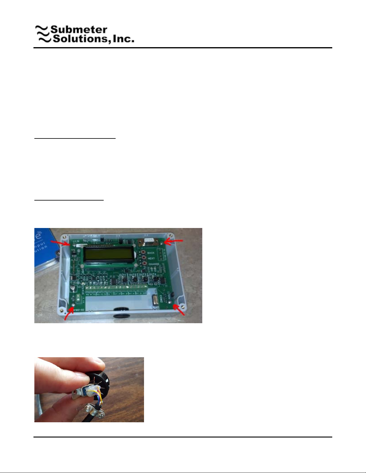
1. Remove the blue cover then remove the 4 mounting screws on the corners of the NoWire circuit board.
Remove the NoWire circuit board from the case.
2. Remove the access plug from the bottom of the NoWire case. Locate the NoWire-GSM serial cable and
carefully push the connector through the plug being careful not pulling out the wires from the connector. Go
slowly and wiggle it attempting to minimize stress on the wires.
45 Logan Ave S, Renton, WA 98057 – phone: 425-228-6831, toll free: 888-64METER Page 1 or 4
www.SubmeterSolutions.com - [email protected]
Page 2
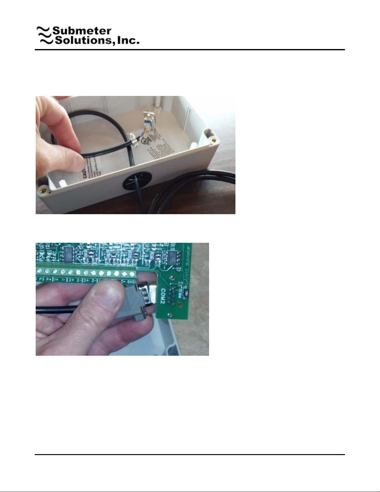
3. Push the connector end of the cable through open hole at the bottom of NoWire and re-insert the access
plug. Pull the cable most of the way through the hole and loop it as shown.
4. Attach the connector cover to connector. Lift the serial connector end of the cable and plug it into the NoWire
Com2 connector. Try to avoid touching the components on the circuit board by holding the board by its edges.
5. Place the NoWire circuit board back in the case laying it down on top of the cable. Don’t force it. Adjust the
cable under the circuit board so it doesn’t bind on the components and metal antenna of the receiver board
underneath. Screw back in the mounting screws to attach the NoWire circuit board back into the case.
6. Re-apply all other wiring such as the power supply, pulse input wires, pulse output wires, etc. Don’t apply
power to NoWire yet.
7. Locate the GSM modem and screw on the antenna and plug in the power supply. Connect and screw down
the 15 pin end of the NoWire-GSM serial cable into the GSM modem.
45 Logan Ave S, Renton, WA 98057 – phone: 425-228-6831, toll free: 888-64METER Page 2 or 4
www.SubmeterSolutions.com - [email protected]
Page 3
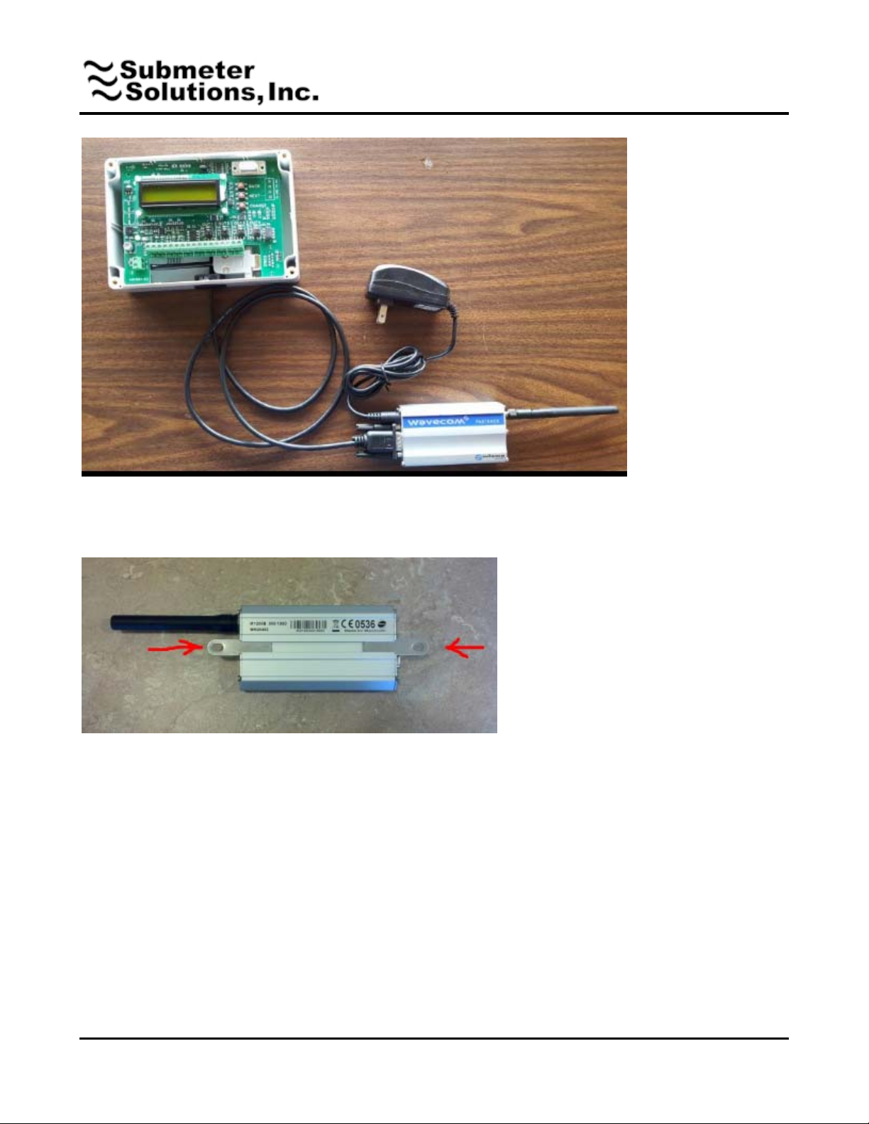
8. Flip the GSM modem over and slide the mounting tabs into the slot on the bottom of the case. Flip it back
over and screw the tabs into the wall to securely mount GSM modem in a location that can be received by the
cellular network, usually right next to the NoWire enclosure works.
9. Apply power to NoWire and the GSM Modem.
45 Logan Ave S, Renton, WA 98057 – phone: 425-228-6831, toll free: 888-64METER Page 3 or 4
www.SubmeterSolutions.com - [email protected]
Page 4
Configuration Instructions:
Reference the NoWire User Manual for navigating throught the setup menus.
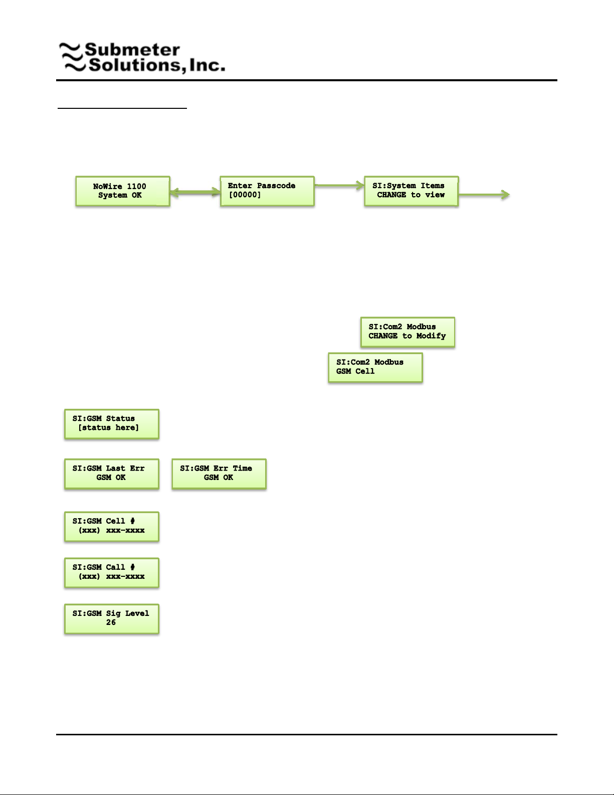
1. Navigate to the System Items setup menu.
CHANGE
BACK
NEXT
(if valid)
User changeable passcode is
entered here. Default is 00000.
CHANGE increments each digit.
NEXT moves to the next digit. If
the displayed passcode is correct
then flow will move to the System
Items in the setup menu.
2. Keep pressing NEXT in the System Items menu until you get to
3. Press CHANGE and NEXT to select “GSM”. Press BACK
4. Press NEXT to cycle thru the following menu items
Current GSM Modem Status: After initialization during startup it should
eventually display “Loop: Chk Signal” and “Loop: Chk Network”
The last error and the time it occurred as seen by the GSM
Modem. Cycling power on NoWire will clear this field. Used
for troubleshooting.
The cellular phone number of the GSM Modem. A Zero number indicates it hasn’t
been read from the GSM modem. Check cable connections, make sure the SIM card
is inserted all the way, and watch the GSM Status menu item.
The phone number to which the GSM Modem calls
Cellular signal level. Levels above 9 are ok. If the level is 0 this may indicate it hasn’t
been read from the GSM modem. Check cable connections, make sure the SIM card
is inserted all the way, and watch the GSM Status menu item.
CHANGE to view
45 Logan Ave S, Renton, WA 98057 – phone: 425-228-6831, toll free: 888-64METER Page
www.SubmeterSolutions.com - [email protected]
4 or 4
 Loading...