

Page 1

NoWire WebConnect™ Ethernet Modem Installation Notes
These instructions show you how to connect up the WebConnect Ethernet Modem to the NoWire equipment as
well as configure it for use in your system.
Note: NoWire COM2 can have the GSM Cell, Ethernet Modem, or Modbus Slave RTU modes operating, Not
multiple at the same time.
Safety and Static Protection:
During this procedure remove power from NoWire and the Ethernet modem. The NoWire circuit board has
statically sensitive components. Though the circuitry is robust avoid static electrical charges whenever possible.
When handling NoWire, whenever possible, hold the circuit board by the edges to avoid touching the
components. Perform this procedure in a low static environment…not on carpet, not wearing nylon clothing, etc.
Discharge any static charges on your body by touching the grounded center screw on a standard electrical
outlet. If possible wear an anti-static wrist strap.
Installation Instructions:
NoWire firmware version must be version 2.02 or higher.
1.Remove the blue cover then remove the 4 mounting screws on the corners of the NoWire circuit board.
Remove the NoWire circuit board from the case.
2. Remove the access plug from the bottom of the NoWire case. Locate the 9 pin serial cable connected to the
WebConnect Ethernet modem. Carefully push the 9 pin connector through the plug being careful not pulling out
the wires from the connector. Go slowly and wiggle it attempting to minimize stress on the wires.
45 Logan Ave S, Renton, WA 98057 – phone: 425-228-6831, toll free: 888-64METER Page 1 or 4
www.SubmeterSolutions.com - sales@SubmeterSolutions.com
Page 2
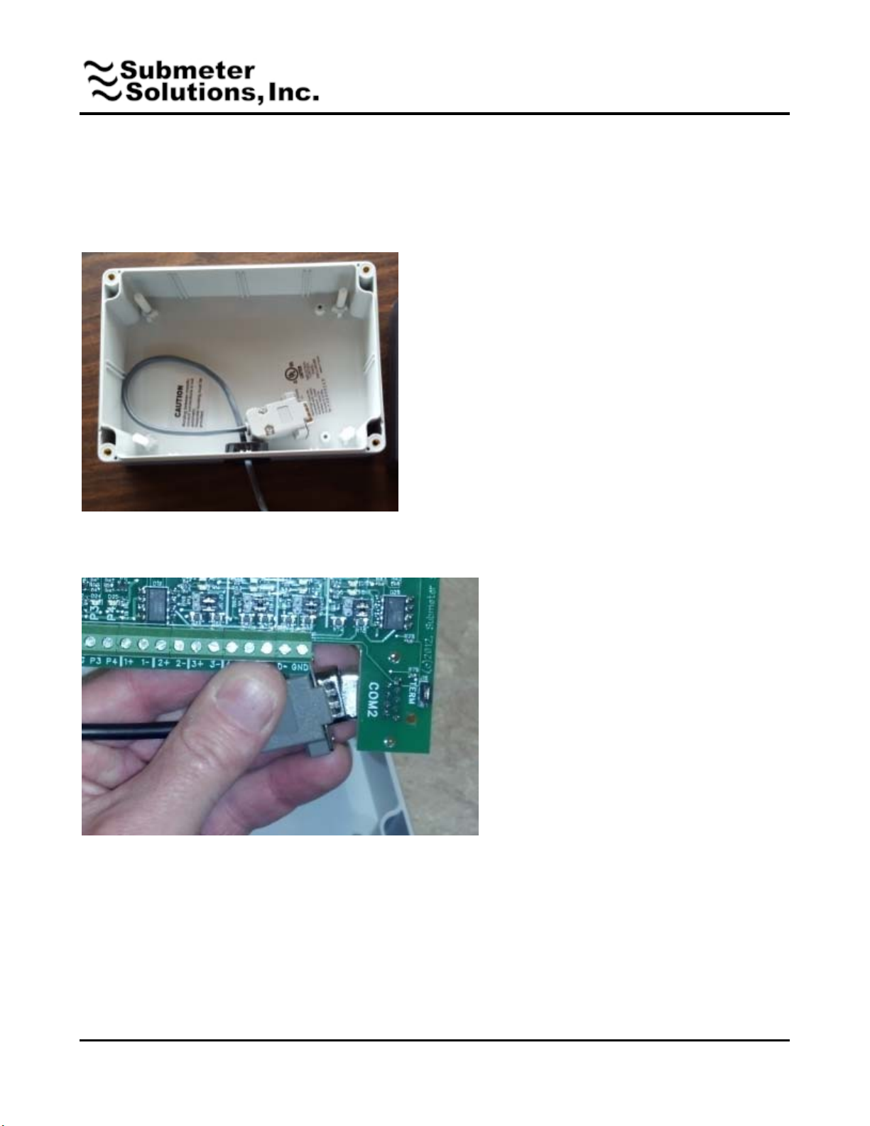
3. Push the connector end of the cable through open hole at the bottom of NoWire and re-insert the access
plug. Attach the connector cover to the conector. Pull the cable most of the way through the hole and loop it as
shown.
4.Lift the serial connector end of the cable and plug it into the NoWire Com2 connector. Try to avoid touching
the components on the circuit board by holding the board by its edges.
5. Place the NoWire circuit board back in the case laying it down on top of the cable. Don’t force it. Adjust the
cable under the circuit board so it doesn’t bind on the components and metal antenna of the receiver board
underneath. Screw back in the mounting screws to attach the NoWire circuit board back into the case.
6. Re-apply all other wiring such as the power supply, pulse input wires, pulse output wires, etc. Don’t apply
power to NoWire yet.
45 Logan Ave S, Renton, WA 98057 – phone: 425-228-6831, toll free: 888-64METER Page 2 or 4
www.SubmeterSolutions.com - sales@SubmeterSolutions.com
Page 3

7. Securely mount the Ethernet modem. It may be most convenient to simply sticky back tape it to the side of
the NoWire enclosure with the two provided sticky back tape squares or you may use the zip tie and zip tie
holder which can be screwed or stuck to a wall.
8. Apply power to NoWire, the WebConnect Ethernet modem, and plug the LAN patch cable into an active RJ45
Ethernet jack. The active Ethernet must have access to the internet and support DHCP. Most Routers installed
by your Internet Service Provider have spare RJ45 jacks in the back which can be used by the WebConnect
Ethernet modem.
45 Logan Ave S, Renton, WA 98057 – phone: 425-228-6831, toll free: 888-64METER Page 3 or 4
www.SubmeterSolutions.com - sales@SubmeterSolutions.com
Page 4

Configuration Instructions:
Reference the NoWire User Manual for navigating through the setup menus.
1. Navigate to the System Items setup menu.
CHANGE
BACK
NEXT
(if valid)
User changeable passcode is
entered here. Default is 00000.
CHANGE increments each digit.
NEXT moves to the next digit. If
the displayed passcode is correct
then flow will move to the System
Items in the setup menu.
2. Keep pressing NEXT in the System Items menu until you get to
3. Press CHANGE and NEXT a couple times to select “Ethernet/Wifi”. Press BACK.
4. Press NEXT to cycle thru the following menu items
This shows current Ethernet Modem Status. At any time you can see various
message displayed indicating progress of the communications with the Ethernet
modem. After initialization during startup it should eventually display:
• “Loop: Chkg Modem”
• “Loop:Enet 01.xx” (modem version number)
• “On: ddd:hh:mm:ss” (how long the modem has been turned on)
• “Loop:Checkng Web”
• “Loop:Web Ok” (this indicates the Submeter Solutions website has connected
successfully.)
“Yes” indicates the Ethernet modem will attempt to automatically retrieve an IP
address from the network DHCP server. “No” indicates a fixed IP address that must
be entered by the user on the next screen. To change this setting Press CHANGE
and NEXT then BACK when done.
If the Auto IP setting above is “Yes” then this displays the IP address provided by the
network to the Ethernet Modem. If the Auto IP setting above is “No” then this is the
user changeable IP address for connecting to the network. To change the IP address
press CHANGE. Then press CHANGE and NEXT to change the IP address. When
done press BACK.
This is the unique MAC address assigned to the Ethenet
modem.
CHANGE to view
45 Logan Ave S, Renton, WA 98057 – phone: 425-228-6831, toll free: 888-64METER Page
www.SubmeterSolutions.com - sales@SubmeterSolutions.com
4 or 4
 Loading...