

Specifications and Main Features
- Model: RGX3905,505D
- Manufacturer: FUJI HEAVY INDUSTRIES LTD.
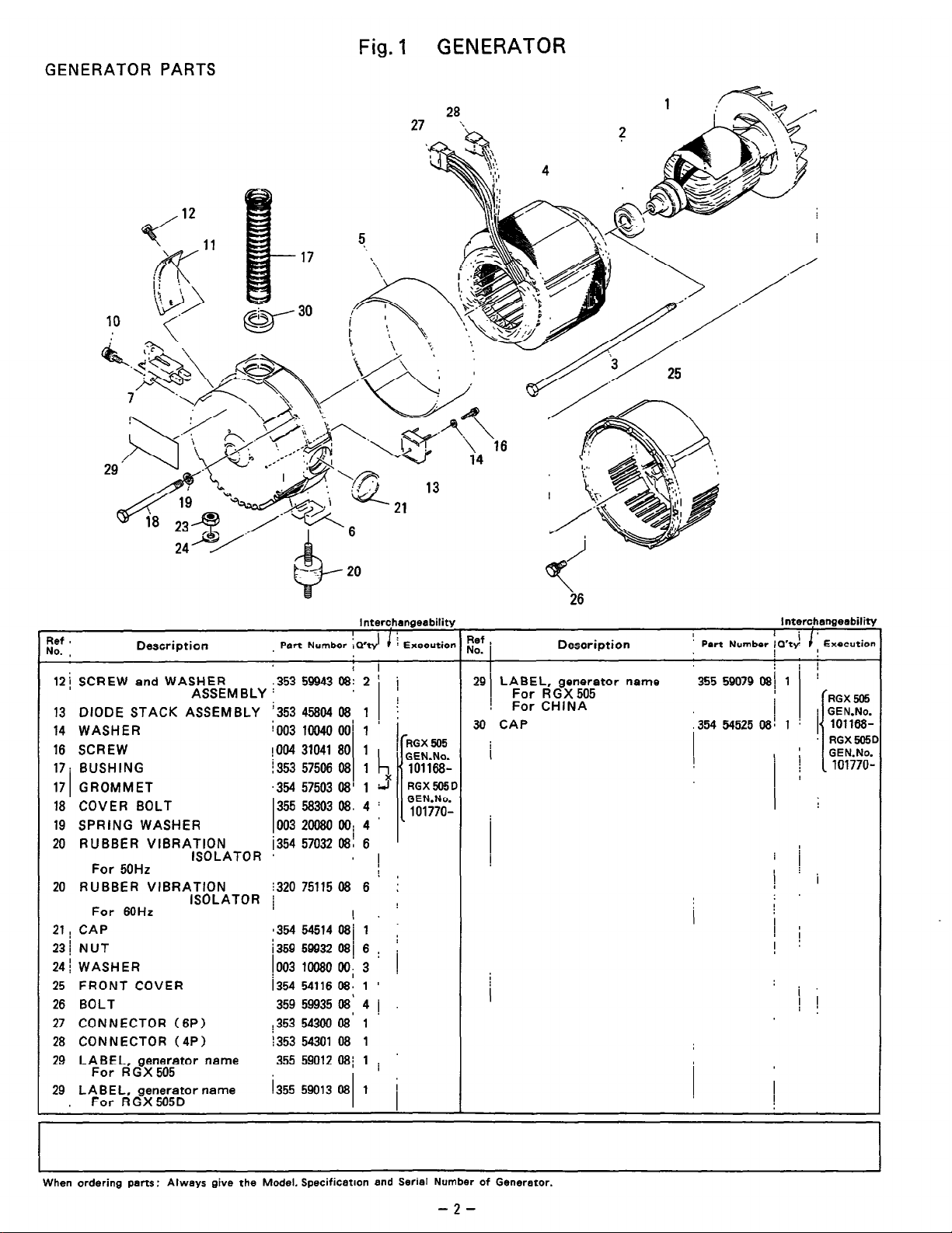
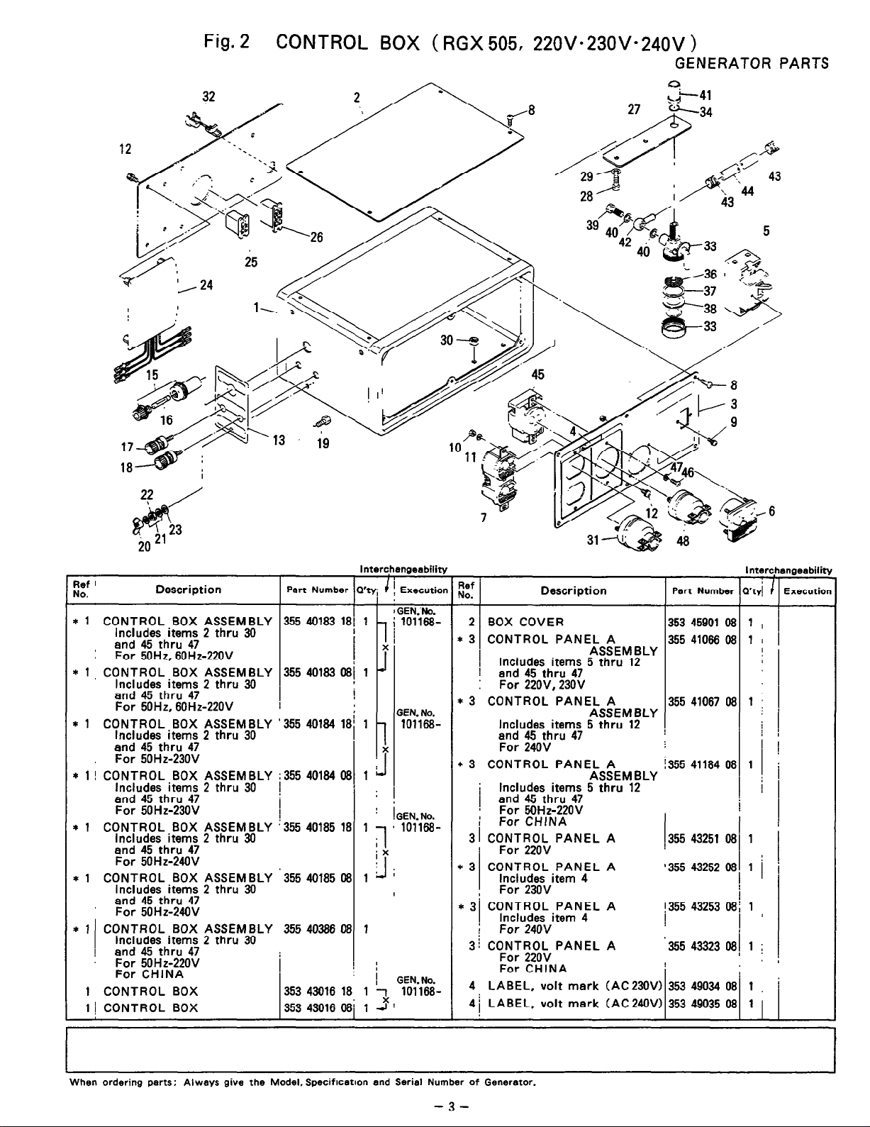
- Always Includes items 2 thru 30
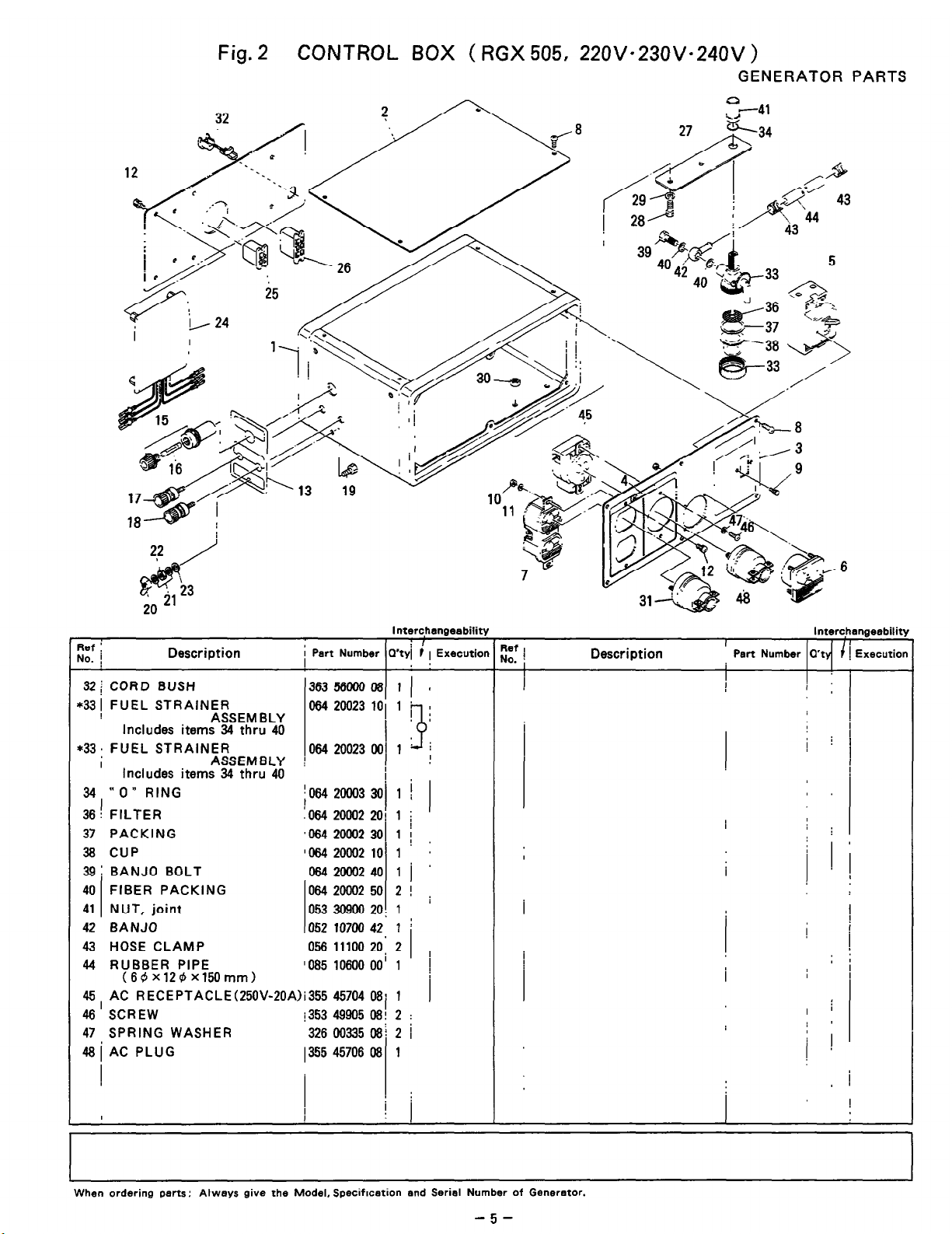
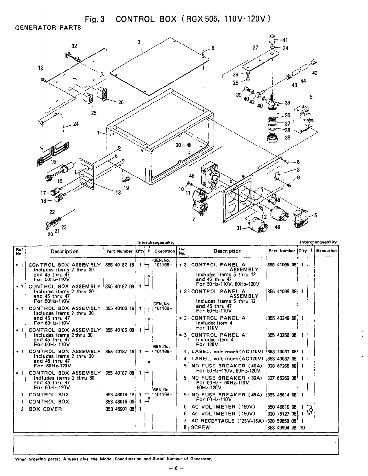
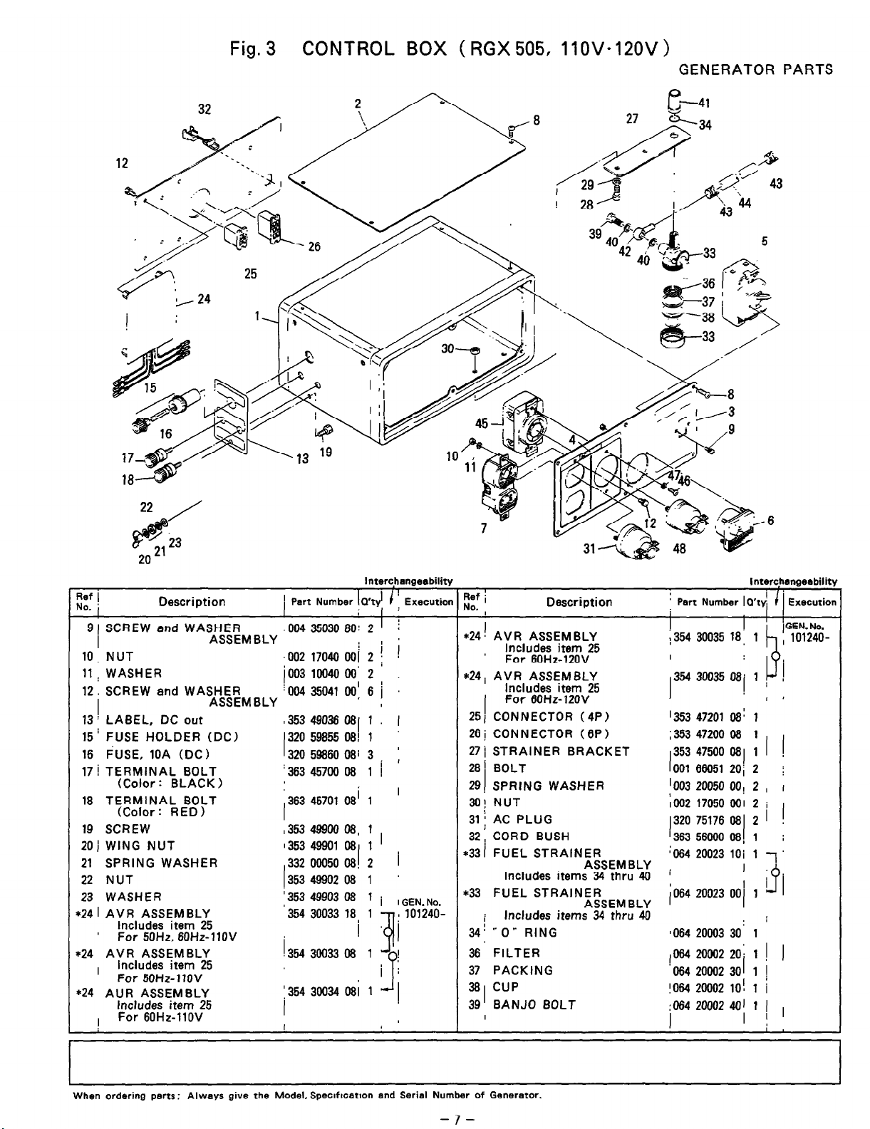
- Control Box assemblies available for the voltage specifications of:
- 220V; 230V; 240V; 110V; 120V
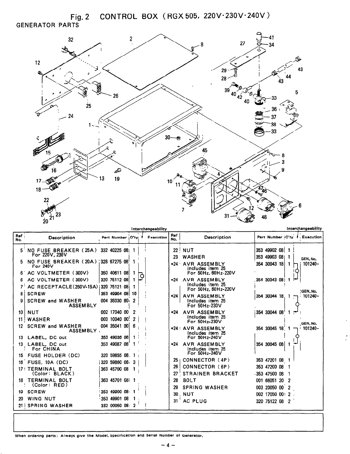
- No Fuse Breakers Options:
- 25 A for 220V, 230 V
- 20 A for 240 V
- AC voltage meter options:
- 300V for models RGX 505 and 505D
- Many types of control panel assembly
- Optional parts like electric starter, oil sensors, control box assemblies are made for particular types of applications and markets
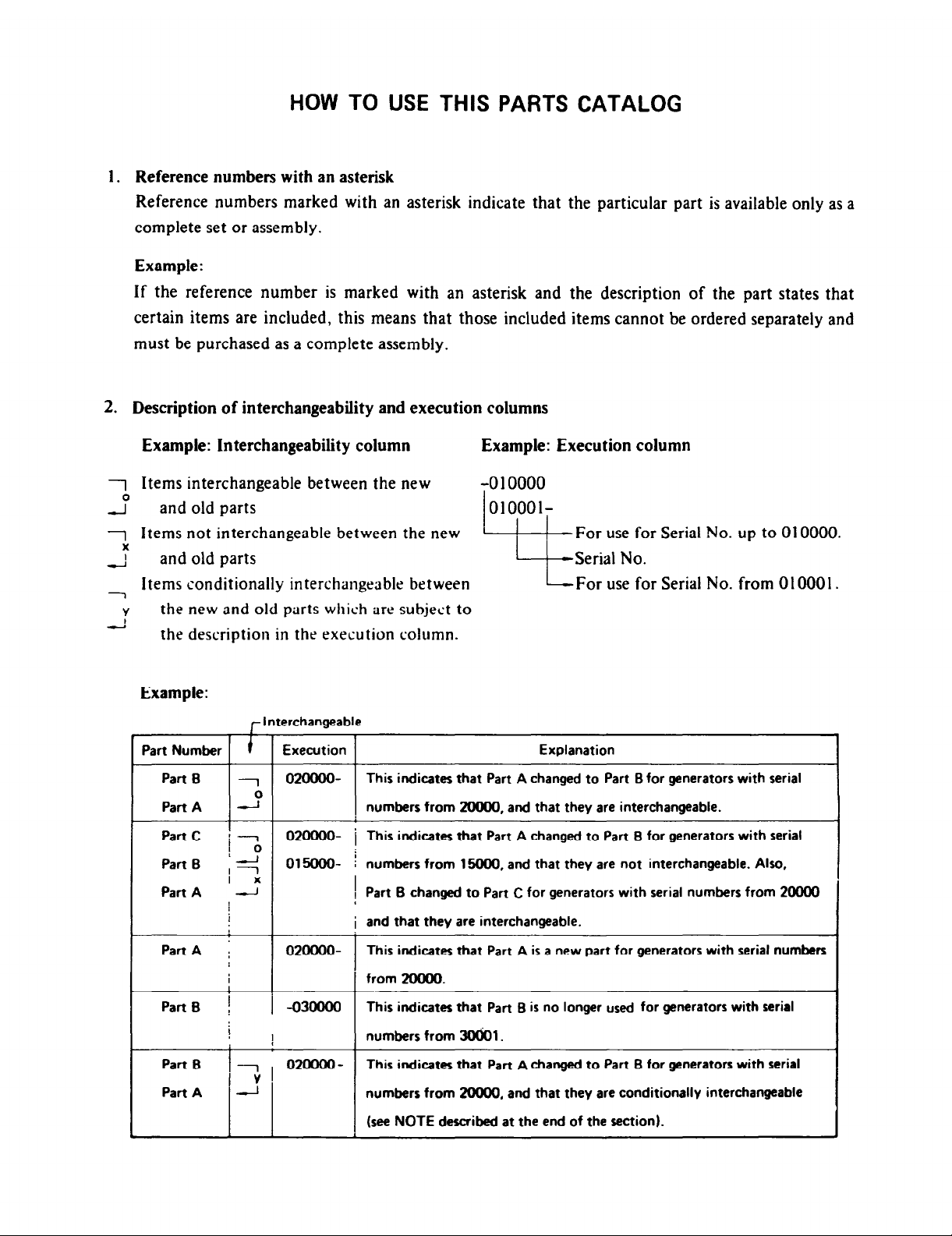
- Many parts are interchangeable between different models for repair and maintenance
Frequently Asked Questions
Q1: What is the model of this generator?
A1: The model is RGX3905,505D.
Q2: Who is the manufacturer of this generator?
A2: The manufacturer is FUJI HEAVY INDUSTRIES LTD.
Q3: What types of control box assemblies are available?
A3: Control box assemblies for 220v,230v and 240v and for 110v and 120v are available.
Q4: Are there options for no fuse breakers?
A4: Yes the options include 25A No Fuse breaker for 220v,230v and 20A No Fuse breaker for 240v.
Q5: Which voltmeter options does the generator have?
A5: The generator boasts an inclusion of 300V AC voltmeter option.
Q6: Is it possible to get any extra components for this generator?
A6: It, indeed, is possible. Some of the extra components that could be available are electric starters, oil sensors, and various control box solutions for the certain applications and markets.
Q7: Are parts interchangeable between models?
A7: Yes, during service and repair, several parts can be exchanged between the generators of different models.
User Manual
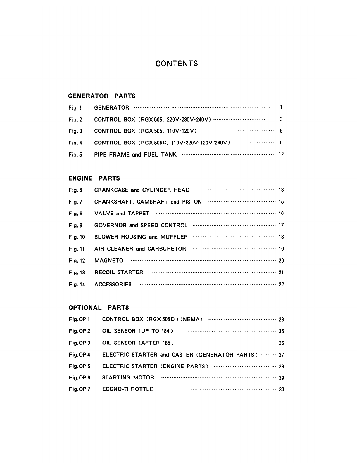
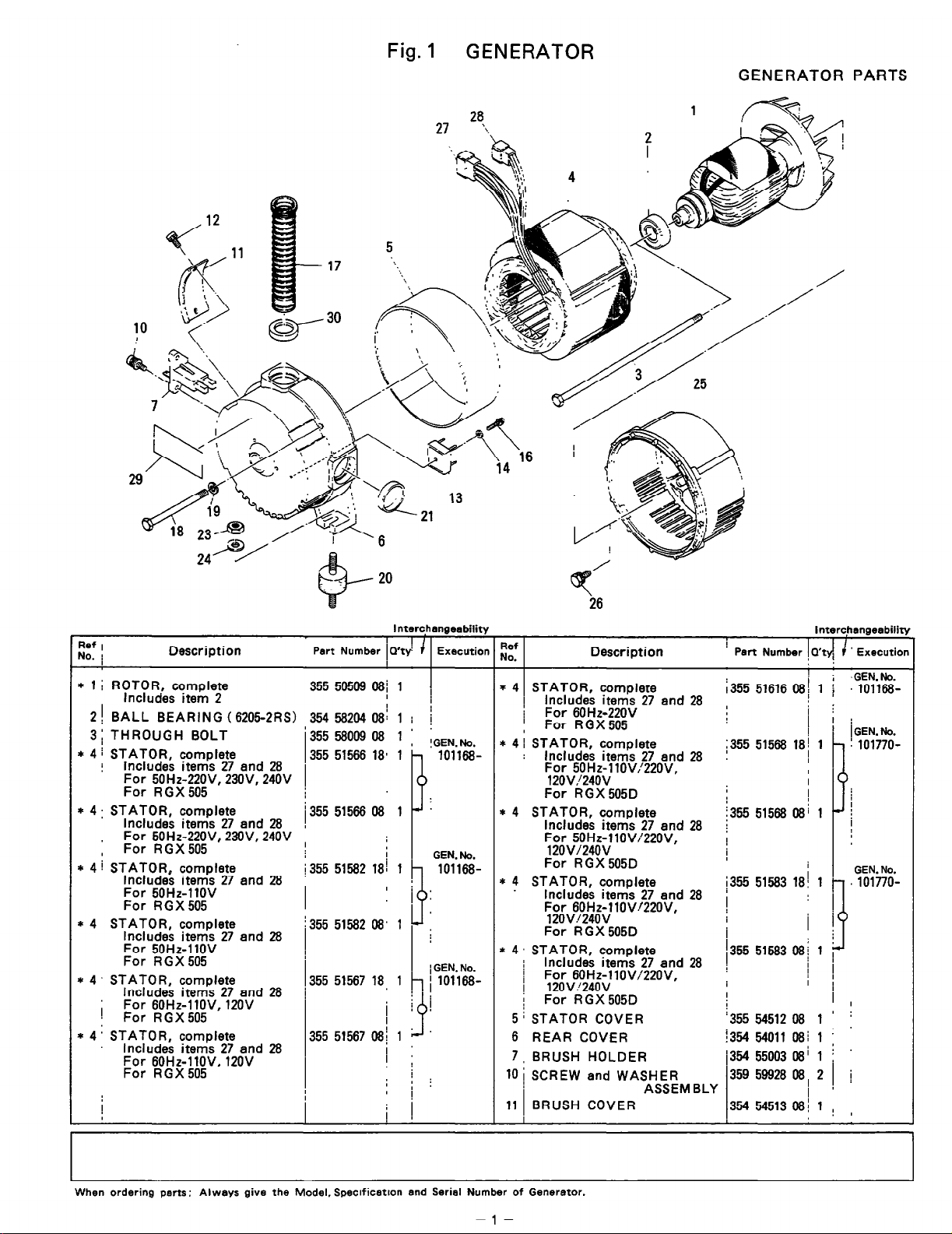
GENERATOR PARTS


ENGINE PARTS


OPTIONAL PARTS


 Loading...