

Page 1
w
-PARTS CATALOG
Generator /
Model
RGX3510
@FUJI HEAVY INDUSTRIES LTD.
ISSUE EMD-GP1082 -
Page 2
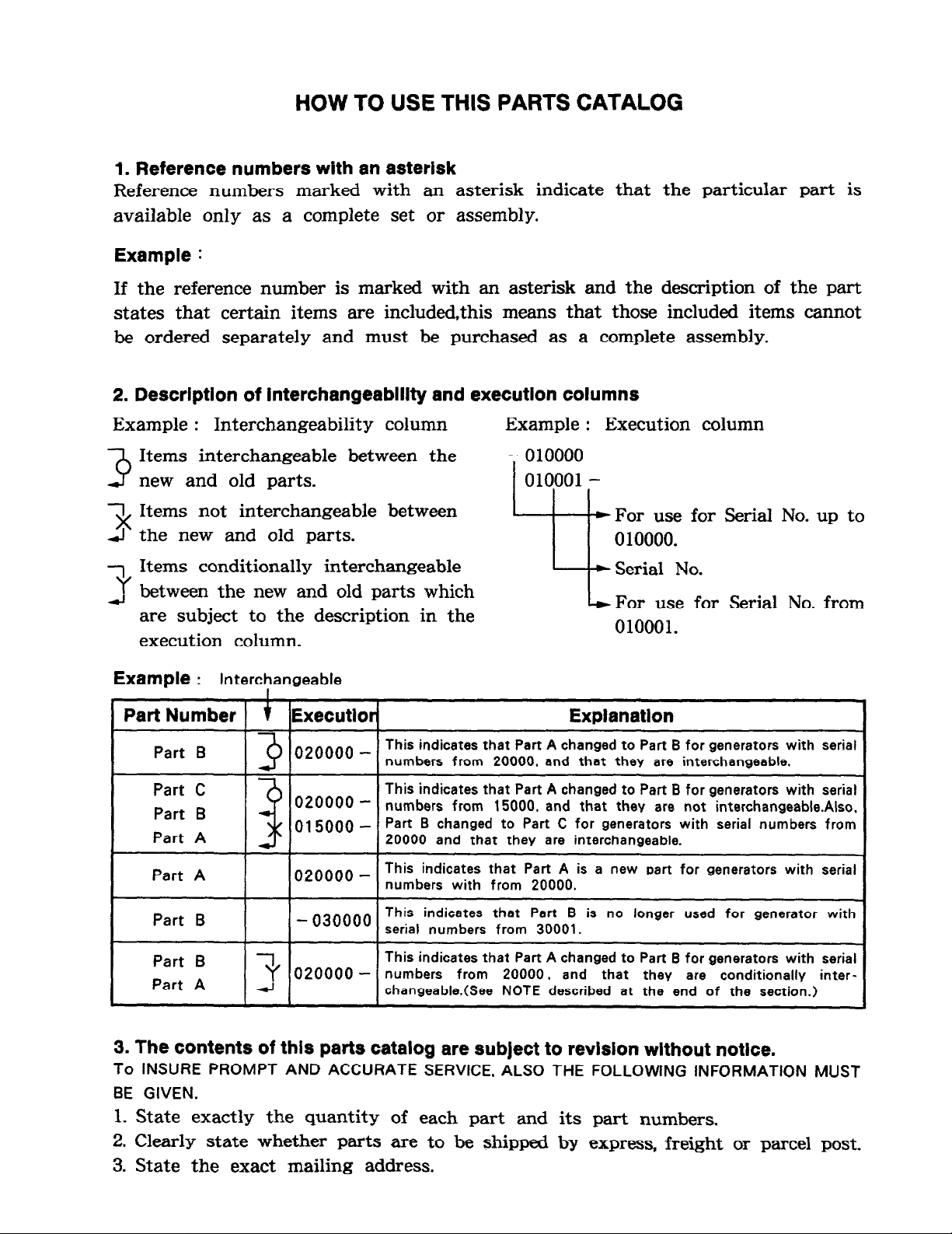
HOW TO USE THIS PARTS CATALOG
1. Reference numbers with an asterisk
Reference numbers marked with an asterisk indicate that the particular part is
available only as a complete set or assembly.
Example :
If the reference number is marked with an asterisk and the description of the part
states that certain items are included.this means that those included items cannot
be ordered separately and must be purchased as a complete assembly.
2. Description of interchangeablllty and execution columns
Example :
Interchangeability column
Example : Execution column
3
3
3
Items interchangeable between the
new and old parts.
Items not interchangeable between
the new and old parts.
Items conditionally interchangeable
For use for Serial No. up to
0 10000.
Serial No.
between the new and old parts which
are subject to the description in the
execution column.
L
For use for Serial No. from
010001.
Example : ,
Interchangeable
Part Number t Executlor Expianatlon
Part B
3
020000 -
This indicates that Part A changed to Part B for generators with serial
numbers from 20000. and that they are interchangeable.
Part C
020000 -
This indicates that Part A changed to Part B for generators with serial
Part B
3
numbers from 15000. and that they are not interchangeabie.Also.
Part A
015000 -
Part B changed to Part C for generators with serial numbers from
20000 and that they are interchangeable.
Part A
020000 -
This indicates that Part A is a new part for generators with serial
numbers with from 20000.
Part B
- 030000
This indicates that Part B is no longer used for generator with
serial numbers from 30001.
Part B
Part A
This indicates that Part A changed to Part B for
generators
with serial
3 020000 -
numbers from 20000. and that they are conditionally interchangeable.(See NOTE described at the end of the section.)
3. The contents of this parts catalog are subject to revision without notice.
To INSURE PROMPT AND ACCURATE SERVICE. ALSO THE FOLLOWtNG INFORMATION MUST
BE GIVEN.
1. State exactly the quantity of each part and its part numbers.
2. Clearly state whether parts are to be shipped by express, freight or parcel post.
3. State the exact mailing address.
Page 3
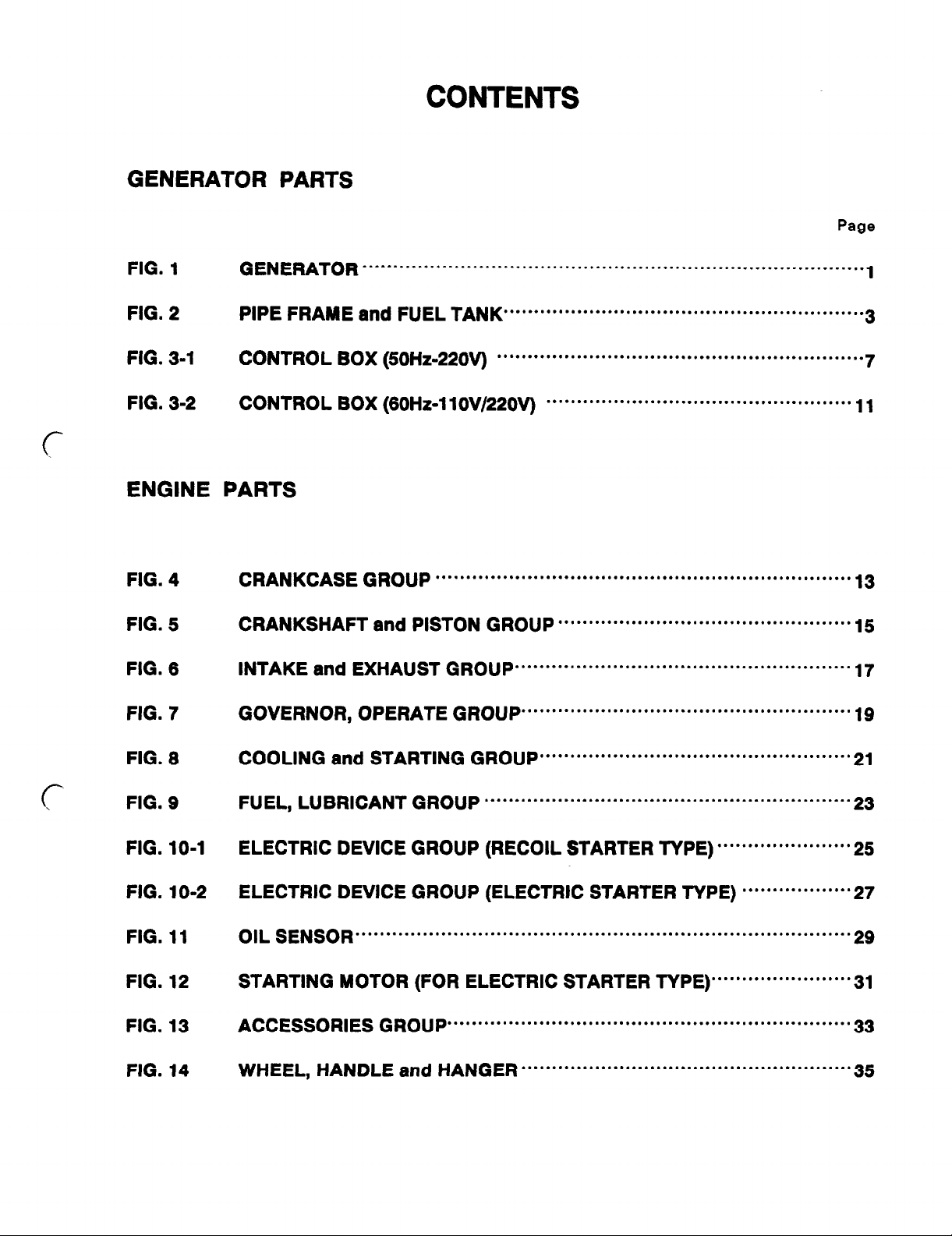
GENERATOR PARTS
CONTENTS
Page
FIG. 1
FIG. 2
FIG. 3-1
FIG. 3-2
FIG. 4
FIG. 5
FIG. 6
FIG. 7
GENERATOR
PIPE FRAME and FUEL TANK
CONTROL BOX (50Hz-220V)
CONTROL BOX (60Hz-11OV/22OV)
CRANKCASE GROUP
CRANKSHAFT and PISTON GROUP
INTAKE and EXHAUST GROUP
GOVERNOR, OPERATE GROUP
. . . ..*............................................................................
. . . . . . . . . . . . . . . . . . . . . . . . . . . . . . . . . . . . . . . . . . . . . . . . . . . . . . . . . . .
. . . . . . . . . . . . . . . . . . . . . . . . . . . . . . . . . . . . . . . . . . . . . . . . . . . . . . . . . . . .
....................................................................
.......................................................
......................................................
. . . . . . . . . . . . . . . . . ..*..............................
................................................
1
3
7
11
13
15
17
19
c-
.
FIG. 8
FIG. 9
FIG. 10-1
FIG. 10-2
FIG. 11
FIG. 12
FIG. 13
FIG. 14
COOLING and STARTING GROUP
FUEL, LUBRICANT GROUP
ELECTRIC DEVICE GROUP (RECOIL STARTER TYPE) “““““““““““ 25
ELECTRIC DEVICE GROUP (ELECTRIC STARTER TYPE) “““““““““ 27
OIL SENSOR
STARTING MOTOR (FOR ELECTRIC STARTER TYPE) “““‘*“““““““‘ 31
ACCESSORIES GROUP
WHEEL, HANDLE and HANGER
.................................................................................
............................................................
..................................................................
...................................................
......................................................
21
23
29
33
35
Page 4
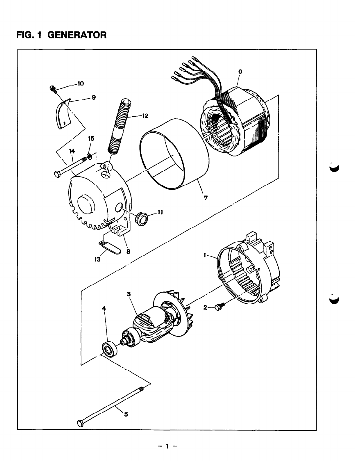
FIG. 1 GENERATOR
Page 5
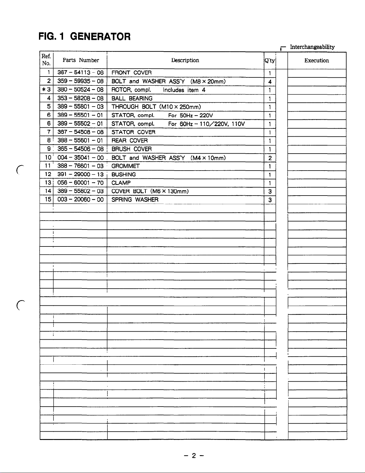
FIG. 1 GENERATOR
r Interchangeability
Ref.
NO.
Parts Number ’ Description
Execution
1 367 -
54113 - 08
FRONT COVER
1
2 359 - 59935 - 08
BOLT and WASHER ASS’Y
(M8 x 20mm)
4
I 3 380 - 50524 - 08
ROTOR, compl. Includes
item 4
1
4 353- 58208-08
BALL BEARING
1
5 389 - 55801
- 03 THROUGH BOLT
(Ml0 x 250mm)
1
6 389 - 55501
- 01 STATOR, compl.
For 50Hz - 220V
1
6 389 - 55502
- 01 STATOR, compl.
For 60Hz - 110/22OV,
11 OV 1
7 367 - 54508
- 08 STATOR COVER
1
8 i 388 - 55601
- 01 , REAR COVER
! 1
: 9 365 - 54506
- 08 ; BRUSH COVER
1 :
10 ’ 004 - 35041
- 00 BOLT and WASHER
ASS’Y (M4 x 10mm)
2
)
(-
1 11 : 388 - 76601 - 03 : GROMMET
lli
12 391 - 29000
- 13 i BUSHING
1
13 ; 056 - 60001
- 70 1 CLAMP
1
14 389 - 55802
- 03 COVER BOLT (M6
X 130mm)
I 3
15 003 - 20060
- 00 SPRING WASHER
3
I
I
: 1
I
c
I
I
I
I
I
I
H
!
I
I
1
I
-2-
Page 6
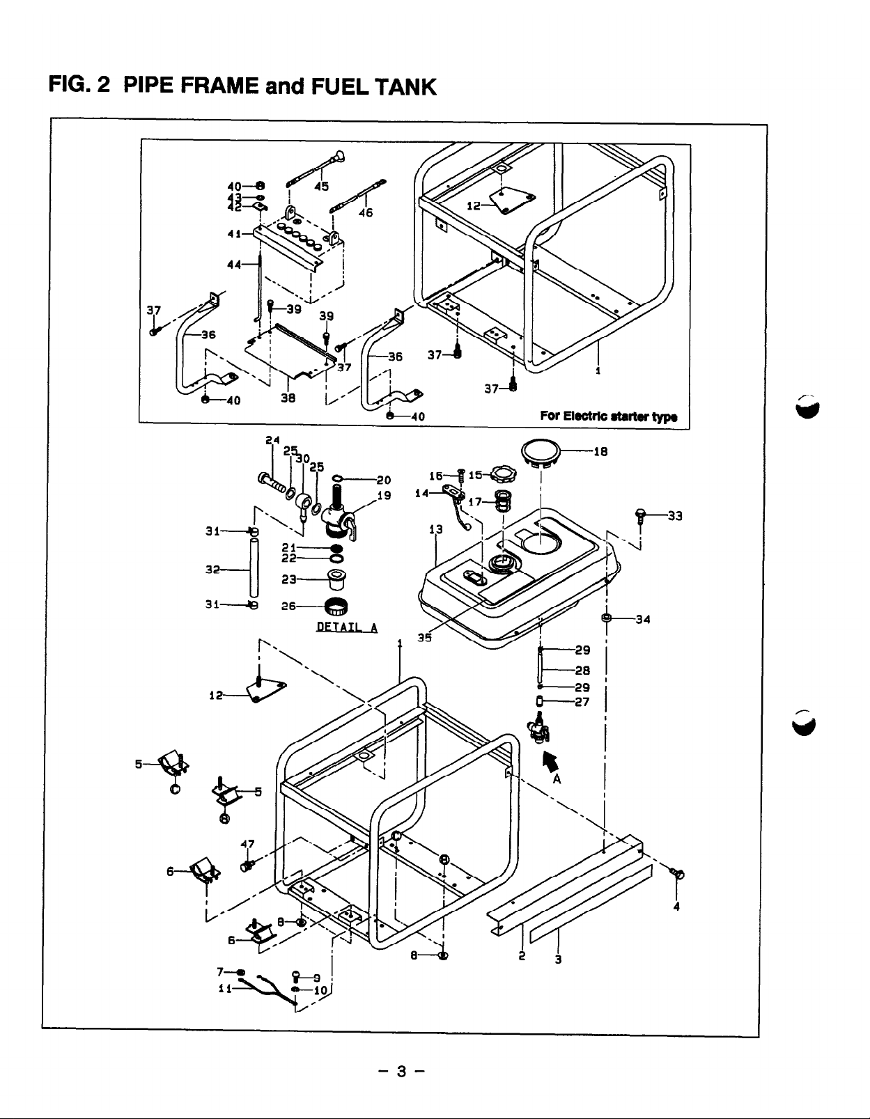
FIG. 2 PIPE FRAME and FUEL TANK
”
-ia
For Elactrlc @artof typa
3i-4
26-e
RJ=TArl A
.
P
4
7-m
Es I
ii
-Ii
-10
/
c
-3-
Page 7
-___-.
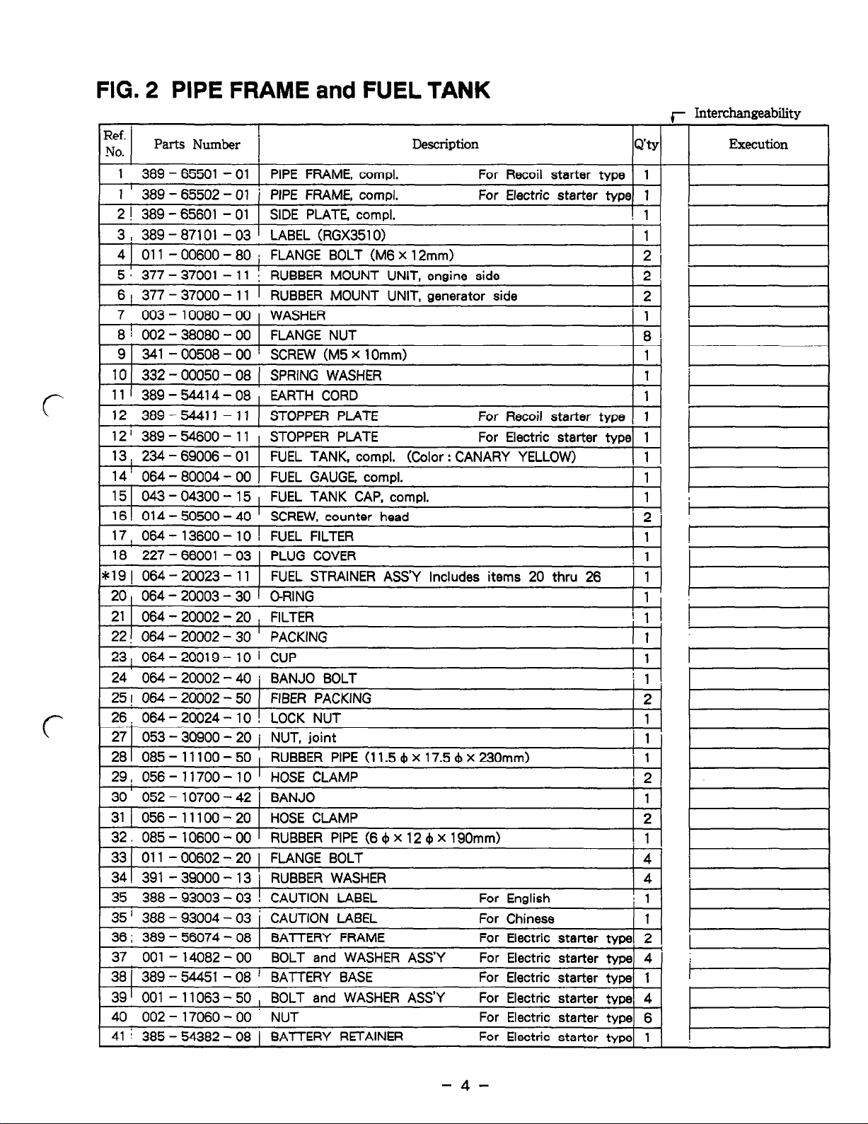
FIG. 2 PIPE FRAME and FUEL TANK
r Interchangeability
.
Ref.
NO.
Parts Number
Description
Q’ty
Execution
1 389 - 65501
- 01 1 PIPE FRAME.
compl. For Recoil
starter type 1
1 I 389 - 65502
- 01 i PIPE FRAME,
compl. For Electric
starter type 1
2 ! 389 - 65601
- 01 1 SIDE PLATE compl.
! 1 I
3 -
- ’
, 389 87101
03 LABEL (RGX3510)
1
4 1 011 - 00600
- 80 : FLANGE BOLT (M6
x
12mm)
2 I
I
5, 377-37001-11
:
J
RUBBER MOUNT UNIT, engine side
’ 2 .
6 ! 377 - 37000 - 11
1 RUBBER MOUNT
UNIT. generator side
2
7 003 - 10080
- 00 WASHER
j 1
8 i 002 - 38080
- 00 FLANGE NUT
8
9 341 - 00508
- 00 ’ SCREW (M5 X 1Omm)
1
*
10 332 - 00050
- 08 1 SPRING WASHER
1 I
11’ 389-54414-08, EARTH CORD
I
1 1
12 389-54411
-11 1 STOPPER PLATE
For Recoil
starter type [ 1
12 i 389 - 54600
- 11 I STOPPER PLATE
For Electric
starter type\ 1
13; 234-69006-01 FUEL TANK, compl. (Color : CANARY YELLOW)
I 1 I
14 ’ 064 - 80004
- 00 FUEL GAUGE compl.
1
15 1 043 - 04300
- 15 , FUEL TANK CAP, compl.
1
16 ! 014 - 50500
- 40 ’ SCREW, counter
head
2 !
17, 064 - 13600
- 10 ! FUEL FILTER
1
18 227 - 66001
- 03 1 PLUG COVER
i 1
lk19 I 064 - 20023
- 11 I FUEL STRAINER
ASS’Y Includes items
20 thru 26 1 I
I I
20, 064 - 20003
- 30 1 CRING
1 1 ’
21 1 064 - 20002
- 20 , FILTER
I 1
I
22! 064 - 20002 - 30
’ PACKING
1
23: 064-20019-10
i CUP
1
I
24 064 - 20002
- 40 i BANJO BOLT
i 1 1
I
25! 064 -20002- 50
( FIBER PACKING
2
26, 064 - 20024 - 10
! LOCK NUT
1
27 1 053 - 30900 - 20
j
NUT, joint
1
281 085- 11100-50
,
RUBBER PIPE (11.5~x17.5~x230mm)
1
29, 056- 11700- 10
’ HOSE CLAMP
I 2
30 052 - 10700 - 42
I BANJO
1
31 i 056-11100-20
I HOSE CLAMP
2
~
32.
085 - 10600 - 00 1
RUBBER PIPE (6 4 X
12 4 X 190mm)
j i-1
33 1 011 - 00602
- 20 1 FLANGE BOLT
4.
34 ! 391 - 39000
- 13 / RUBBER WASHER
4
I I
35 388 - 93003
- 03 ! CAUTION LABEL
For English
: 1 ’
35 ’ 388 - 93004
- 03 ; CAUTION LABEL
For Chinese
I 1
36 ; 389 - 56074 - 08 1 BATTERY FRAME
For Electric starter type1 2
I
I
~. .
37 001 - 14082
- 00 BOLT and WASHER
ASS’Y For Electric
starter type 4
38 ( 389 - 54451
- 08 ! BATTERY BASE
For Electric
starter type 1
39 I 001 - 11063 -
50 , BOLT and WASHER
ASS’Y For Electric
starter type1 4 1
40 002 - 17060 -
00 NUT
For Electric
starter type 6
41 i 385 - 54382-
08 j BATTERY RETAINER
For Electric
starter type 1
I
-4-
Page 8
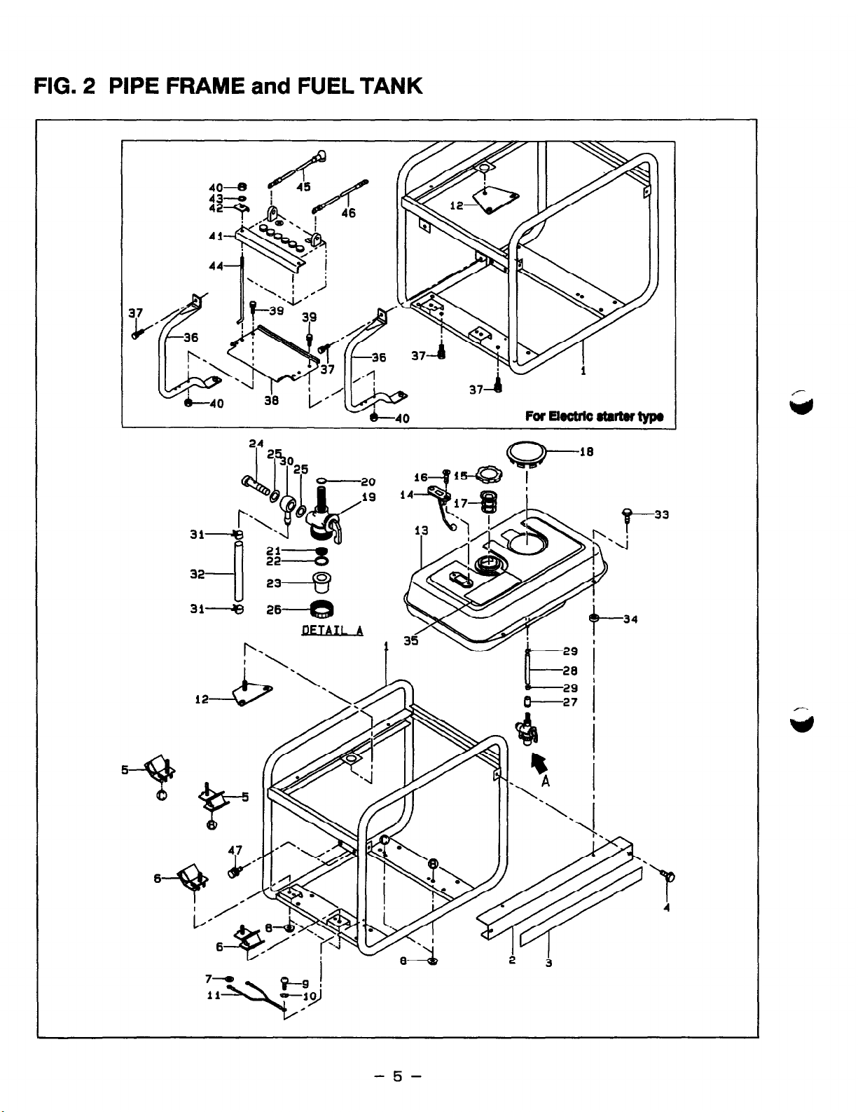
FIG. 2 PIPE FRAME and FUEL TANK
-20
k
33
r-
ii=35
.4
32
a-3
31.--&i
=-e
/
AJl A
T-
34
P-.
29 i
6
-5-
Page 9
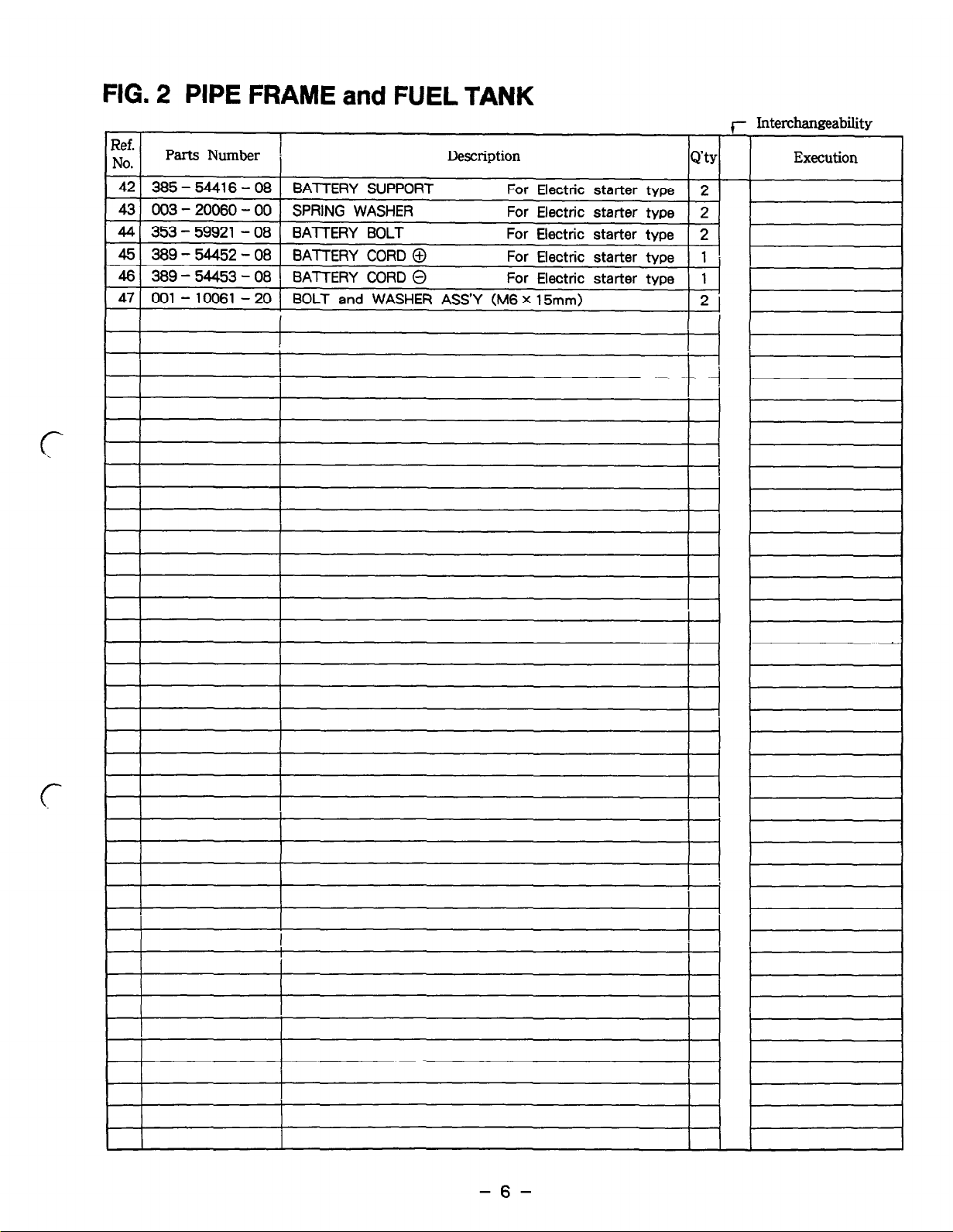
FIG. 2 PIPE FRAME and FUEL TANK
Ref. 1
r Interchangeability
I
No. 1
Parts Number (
Description
QIY
Execution
I
42 385 - 54416 - 08 BATTERY SUPPORT For
Electric
starter type 2
I
43 003 - 20060
- 00 SPRING WASHER
For Electric
starter type 2
44 353 - 59921
- 08 BATTERY BOLT
For Electric
starter type 2
45 389 -
54452
- 08
BATTERY CORD 0 For Electric
starter
type 1
46 389- 54453
- 08 BATTERY CORD @ For Electric
starter type 1
47
001 - 10061
- 20 BOLT and WASHER
ASS’Y (M6 X 15mm)
2
I
I
-6-
Page 10

FIG. 3-1 CONTROL BOX (50Hz-22OV)
/ -y
sffi
22
\
I 24
I
For Elac!tlc
8taitar type
-15
-4
-5
-23
Page 11
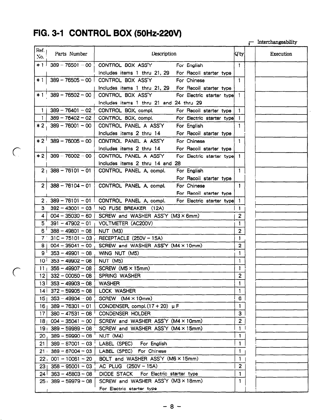
FIG. 3-I CONTROL BOX (50Hz-22OV)
c
r Interdmweabilitv
7
Ref. 1
so. j
Parts Number
Description
Q’ty
Execution
* 1 1 389 - 76501 - 00 ’ ! CONTROL BOX ASS’Y For English 1
I
Includes items 1 thru 21, 29 For Recoil starter type ’
* 1 389 - 76505 - 00 ! CONTROL BOX ASS’Y For Chinese 1 v
1 Includes items 1 thru 21, 29 For Recoil starter type ’
* 1 1 389 - 76502 - 00 (
! Includes items 1 thru 21 and 24 thru 29
! 1 i 389 - 76401 - 02 CONTROL BOX, compl. For Recoil starter type 1
1 (
CONTROL BOX ASS’Y For Electric starter type 1 !F
389 - 76402 - 02 ! CONTROL BOX, compl. For Electric starter type 1 :
* 2 ) 389 - 76001 - 00
Includes items 2 thru 14
For Recoil starter type
l !
* 2 ’ 389 - 76005 - 00 1
:
CONTROL PANEL A ASS’Y For English E
CONTROL PANEL A ASS’Y For Chinese 1
Includes items 2 thru 14 For Recoil starter type
* 2 389 - 76002 - 00 CONTROL PANEL A ASS’Y For Electric starter type 1
Includes items 2 thru 14 and 28
2 ! 388 - 76101 - 01 CONTROL PANEL A, compl. For English
‘I---
l
For Recoil starter type
2 ) 388 - 76104 - 01 i CONTROL PANEL A, compl. For Chinese
I
For Recoil starter type
‘I E
2 I 389 - 76101 - 01 :
3 392 - 43001 - 03 !
CONTROL PANEL A, compl. For Electric starter type 1 :-
NO FUSE BREAKER (12A) I 1
4 ( 004 - 35030 - 60 (
5 :
SCREW and WASHER ASS’Y (M3 X 6mm) p 7
391 - 47902 - 01 1 VOLTMETER (AC200V) 1
6 ’ 388 - 49801 - 08 1 NUT (M3) 2
7 31 C - 75101 - 03 ; RECEPTACLE (25OV - 15A) ( 1
8 j 004 - 35041 - 00 , SCREW and WASHER ASS’Y (M4 x 1Omm) 2
9 ! 353 - 49901 - 08 WING NUT (M5) ! 1
10 1 353 - 49902 - 08
11 1 356 - 49907 - 08 SCREW (M5 X 15mm) 1
12 j 332 - 00050 - 08
NUT (M5) 1 I=
SPRING WASHER 2
131 353-49903-08 * WASHER 1
14 / 372 - 59905 - 08 LOCK WASHER 1
15 1 353 - 49904 - 08 SCREW (M4 x 10mm) 6
16 1 389 - 76301 - 01
17 1
380 - 47531 - 08 CONDENSER HOLDER
18 ; 004 - 35041 - 00 ( SCREW and WASHER ASS’Y (M4 X 1Omm)
19 I 389 - 59989 - 08
CONDENSER, compl.0 7 + 20) u F y;i F
SCREW and WASHER ASS’Y (M4 x 15mm)
20, 389- 59990 -08 ’
21 1 I 389 - 87001 - 03 I LABEL (SPEC) For English k------
21 : 389 - 87004 - 03
NUT (M4) I:! 1 b
LABEL (SPEC) For Chinese /-
22, 001 - 10061 - 20 , BOLT and WASHER ASS’Y (M6 X 15mm) I 1 I
23 1 358 - 95001 - 03 ; AC PLUG (25OV - 15A) -
24 ! I 363 - 45803 - 08
DIODE STACK For Electric starter type
25 ! 389 - 59979 - 08
SCREW and WASHER ASS’Y (M3 X 18mm)
For Electric starter type
-8-
Page 12
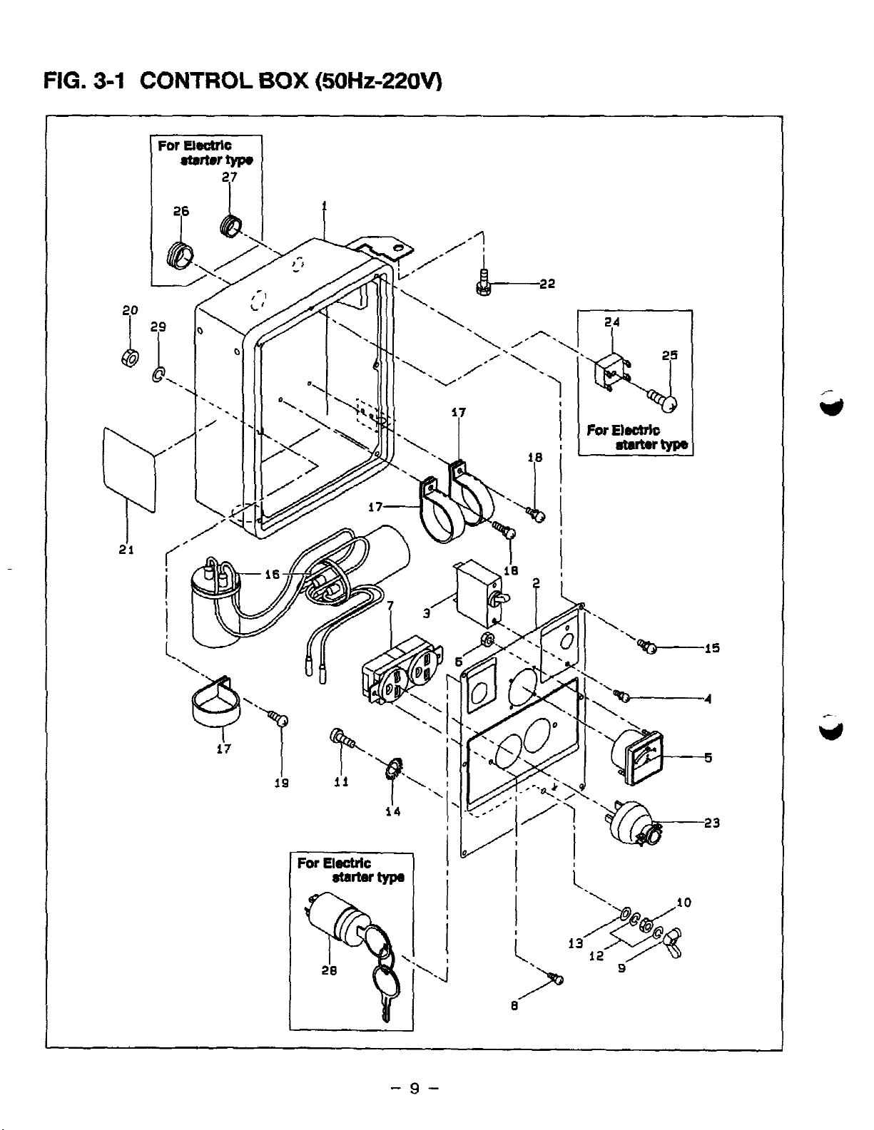
FIG. 3-1 CONTROL BOX (50Hz922OV)
For
libctrk
otarter
typo
-7
27
I
2p
For Electric
starter type
Page 13

FIG. 3-1 CONTROL BOX (5OHz9220V)
r Interchangeability
Ref.
No.
Parts Number Description
Q’ty
Execution
26 385 - 57511 - 08 GROMMET
For Electric starter tvtm 1
27 355 - 57509 - 08 GROMMET
For Electric starter type 1
28 066 - 00003- 00 KEY SWITCH
For Electric starter tvtx 1
29 ] 332 - 00050-08 SPRING WASHER
1 1
I I I
- 10 -
Page 14

FIG. 3-2 CONTROL BOX (60Hz-1 IOV / 22OV)
Page 15

FIG. 3-2 CONTROL BOX (6OHz-1 IOV / 22OV)
t- Interchangeability
Ref. j
I
No. I
Parts Gmber j Description
Q'ty
Execution
* 1 j 389 - 76503 - 00 i CONTROL BOX ASS’Y
For Recoil starter type 1 1 1
/
i Includes items 1 thru 21, 29 thru 31
I i
5
1 ; 389 - 76504
- 00 ) CONTROL BOX
ASS’Y For Electric
starter 1 /
! Includes items
1 thru 21. 24 thru 31
type\
,
I
I
1 1 389 - 76401
- 02 ) CONTROL
BOX, compl. For Recoil
starter type 1 1 I
1 !
389 - 76402
- 02
I
i
CONTROL
BOX, compl. For Electric
starter type/ 1
* 2 ! 389 - 76003 - 00 [ CONTROL
PANEL A ASS’Y
Includes items 2 thru 14 1 1 1
I
1 30 and 31 For Recoil
starter type ) I
* 2 / 389
- 76004
- 00 CONTROL PANEL
A ASS’Y Includes
items
2 thru
14 / 1
I
i 28 thru 31
For Electric starter type’
2 j 388 - 76102 - 01 / CONTROL PANEL A, compl. For Recoil starter type r-j -1
2 j 389 - 76102 - 01 I CONTROL PANEL A. compl.
For Electric starter tvoel 1 1
t
..~
3 1 392 - 43002-
03 1 NO FUSE BREAKER.(14A)
I 1 1
4 1 004 - 35030
- 60 ! SCREW and WASHER ASS’Y (M3 X 6mm)
4
5 ! 391 - 47802
- 01 1 VOLTMETER (AC1 OOV)
1
6 I 388 - 49801
- 08 i NUT (M3)
2
7 ! 343- 11362-
18 i RECEPTACLE (125V- 15A)
1
8 i 004 - 35041 - 00 1 SCREW and WASHER
ASS’Y
(M4 x 10mm)
9 / 353 - 49901 -
08
! WING NUT (M5)
10 i 353 - 49902
- 08 1 NUT (M5)
1 1 (
I
11 i 356 - 49907
- 08 I SCREW (M5 x 15mm)
I 1 I
12 i 332 - 00050
- 08 / SPRING WASHER
121
13 j 353 - 49903
- 08 j WASHER
1 1
I
14 : 372 - 59950
- 08 i LOCK WASHER
1
15 I 353 - 49904
- 08 i SCREW (M4 x 1 Omm)
6
16 I 389 - 76301
- 01 j CONDENSER, compl. (17 + 20) p F
1
17 ! 380 - 45731
- 08 I CONDENSER HOLDER
3
18 ! 004 - 35041
- 00 ! SCREW and WASHER ASS’Y (M4 X 10mm)
2
19 I 389 - 59989
- 08 \ SCREW and WASHER ASS’Y (M4 X 15mm)
1
20 / 389 - 59990
- 08 1 NUT (M4)
1
21 i 389 - 87002
- 03 1 LABEL (SPEC)
1
22 \ 001 - 10061
- 20 1 BOLT and WASHER ASS’Y (M6 X 15mm)
1
23 j 320 - 75176
- 08 t AC PLUG (125V - 15A)
I 2
24 j
363 - 45803
- 08 1 DIODE STACK
For Electric
starter type 1
I
25 j 389 - 59979
- 08 ) SCREW and WASHER ASS’Y (M3 X 18mm)
l I I
I
For Electric starter type
261
385- 57511
-08 1 GROMMET
For Electric
starter
type
1
27 1
355 - 57509
- 08 i GROMMET
For Electric
starter tvpe 1 I
28 ! 066 - 00003 - 00 i KEY SWITCH
1
For Electric
starter tvnel
1 I
I
29! 332- 00050-08 ! SPRING WASHER
I 1 !
30 ! 378 - 45738 - 08 : RECEPTACLE (250V - 15A) I 1 1
31 i 004 - 35041
- 00 i SCREW and WASHER ASS’Y (M4 x 1Omm)
21
32 i 358 - 95001
- 03 [ AC PLUG (250V - 15A)
1
I
I
- 12 -
Page 16

FIG. 4 CRANKCASE GROUP
,
- 13 -
3
J
Page 17

FIG. 4 CRANKCASE GROUP
c
(--
* 1 1 234 - 10101 CRANKCASE, compl. Includes items 2 thru 7
I
For Recoil starter type
Ref.
No.
Parts Number
Description
r Interchangeability
Q’ty
Execution
* 1 1 234- 10102-31 CRANKCASE, compl. Includes items 2 thru 7 1
!
I
For Electric starter type
I I
2 1 227 - 14202 - 03 1 VALVE GUIDE over size
121
I
3 j 044-03000-30 OIL SEAL (TB 3O&x45~x8mm) 1
4 1 060 - 03000 - 20 BALL BEARING (BB 6206C3) 1
5 i 031 - 00600 - 20 DOWEL PIN 2
6 1 010 - 50802 - 90 STUD. muffler 2
7) 010-50601-91 STUD. carburetor 2
*8! 234- 11001 -01 MAIN BEARING COVER, compl. tncludes items 9 and 11 1
101 044-03000-30
I
OIL SEAL (TB 30Qx45&x8mm)
I 1 I
11 060 - 03000 - 20 1 BALL BEARING (BB 6206C3) 1
12 234 - 45001 - 01 1 GOVERNOR GEAR, compl. 1
13 205 - 41901 - 03 GOVERNOR SLEEVE 1
14 227 - 63601 - 03 OIL GAUGE 1
15 021 - 31600 - 20 GASKET 1
16 234 - 13102 - 03 CYLINDER HEAD 1
17 234 - 15001 - 01 GASKET, compl.. head 1
18 234 - 16001 - 03 GASKET. bearina cover 1
19 040-11400-30 PLUG 2
20 021 - 11400 - 20 GASKET 2
21 1 234 - 14302 - 11 1 TAPPET COVER. compl.
I 1 I
221 234- 14401 -01 BREATHER PLATE, compl. 1
23 1 234 - 16006 - 03 GASKET. tappet cover 1
24 234 - 16007 - 03 GASKET, breather plate 1 1
25 085 I - 10800 - 00 RUBBER PIPE (8 4 x 11 4 X 75mm) I 1
26 011 - 00800 - 10 FLANGE BOLT 8
27 001 - 14082 - 80 BOLT and WASHER ASS’Y 8
28 1 011 - 00600- 20 1 FLANGE BOLT
29 1 002 - 38080 - 00 ( FLANGE NUT
lil
* 1 234- 99001 -07 GASKET SET Includes items 15, 17, 18, 23, 24 1
and FIG. 6 Ref. No. 10, 16, 19 and 20
- 14 -
Page 18

FIG. 5 CRANKSHAFT and
PISTON GROUP
13
I
4
4
- 15 -
3
3
Page 19

FIG. 5 CRANKSHAm and PISTON GROUP
f Interchangeability
Ref.
No.
Parts Number
Descri~Lon
Q’ty
Execution
* 1 234 - 20701 - 11
CRANKSHAFT. compl. Includes item
2
1
I
11 002 -
18180 - 00 NUT, flywheel
]
1
12 003 - 20180
- 00 SPRING WASHER,
flywheel
!
1
13 032 - 30300
- 10 WOODRUFF KEY,
flywheel
1
I
I
I
I
1
’ I
1
I
I
I
I
- 16 -
Page 20

FIG. 6 INTAKE and EXHAUST GROUP
UP TO MAR. ‘95
Page 21

FIG. 6 INTAKE and EXHAUST GROUP
t- Interchangeability
Ref. 1
NO.
i
Parts Number
Description
I
I
!
Q3Yl
1 Execution
I
1 234 - 31901
- 00 CAMSHAFT ASS’Y For Recoil
starter type 1
1 234 - 31701
- 03 CAMSHAFT For Electric
starter type 1
2 -
-
, 234 33301
03 TAPPET
2:. l!!!sE
3 227 - 33601
- 03 VALVE SPRING
/
4 234 - 33701
- 03 SPRING RETAINER
5 I 234 - 33401
- 03 i INTAKE VALVE
1
6 234 - 33501
- 03 EXHAUST VALVE
7 234-30101
-01 MUFFLER, compl.
8 j 234 - 34201
- 01 MUFFLER COVER. compl.
Il! I
J
I
9 234 - 35301 - 01
MUFFLER BRACKET
10 234 - 35202 - 01
GASKET, compl., exhaust
11 002-19080-00.
NUT
12. 011 - 00600 - 10
FLANGE BOLT
ii ::
13 : 011 - 00600 - 20
FLANGE BOLT
t 14 1 234 - 32624 - 00 :
AIR CLEANER ASS’Y includes items
15 and 16 1
t14 234 - 32604 - 10
AIR CLEANER ASS’Y includes items
15 thru 17
15 234 - 32604 - 07
CLEANER ELEMENT SET
16 234 - 36003 - 08
GASKET, air cleaner
17 107 - 32733 - 08
LABEL, air cleaner
18 234 -
32901
- 03 !
INSULATOR
19 234 - 35901 - 03 1
GASKET, insulator
20 234 - 35902 -
03 GASKET 2, insulator
21 001 - 10061 -
20 , BOLT and WASHER ASS’Y
22 ’ 226 - 39212 -
00 NUT an
22 002 - 17060 -
00 NUT
231 003- 20060-
00 ! SPRING WASHER
24 ( 234 - 36501 - 01 1 LOCK WASHER
I
I
- 18 -
Page 22

FIG. 7 GOVERNOR, OPERATE GROUP
Page 23

.*
.
FIG. 7 GOVERNOR, OPERATE GROUP
c
r Interchangeability
Ref.
No.
Parts Number Description
Q’ty
Execution
1 234 - 42301 - 01 GOVERNOR LEVER. comcd.
1
I .
I
I
I
I
1
I
I
1
I
I
r
r
-
20
-
Page 24

FIG. 8 COOLING and STARTING GROUP
7
4
I
i9
17
i
-
21
-
Page 25

r
-.
c
FIG. 8 COOLING
and
STARTING GROUP
+- Interchangeability
Ref.
I
No. 1
Parts Number ;
Description
.Q’ty :
Execution
1 234 - 51549 - 06 BLOWER
HOUSING, compl. For Recoil
starter
type 1 1
1 234
- 51420
- 06
BLOWER HOUSING. compl. For Electric
starter
type: 1 )
2 234 - 91701
- 03 LABEL trade
mark
!1
3 073 - 20035
- 50 LABEL, stop switch
For Recoil
starter tvpe 1 1
4 011 - 00600
- 20 FLANGE BOLT
10 ’
5
234 -
52601 - 03 CYLINDER BAFFLE
6 234
- 52801 - 13 HEAD COVER
$7 1 234
- 50221 - 10 RECOIL STARTER
ASS’Y
Includes items 8 thru
17 1
8 ! 234 - 50120
- 18 REEL, compl.
i
1
9 i 161 -50125-08
RATCHET
2
10 253 - 50115 - 08
SPIRAL SPRING
1
11 . 227 - 50131 - 08
FRICTION SPRING
1
12 227 - 50135 - 08
, RETURN SPRING
2 ,
13 , / 161 - 50150 - 08
RATCHET GUIDE
1
14 I 227 - 50152 - 08
:
SET SCREW (M6)
1
15 234-50111 -08
! ROPE
1
16 206 - 50101 - 08
! HANDLE
1
17 : 234 - 50146 - 18
1 STARTING PULLEY
1
181 011 -00600-10
( FLANGE BOLT
19 1 - 00600 - 30
I
141
011
FLANGE BOLT
; 1 I
I
I
I
I
I
I
I
I
1
i 1
iUPT0 JUNE ‘95 /
- 22 -
Page 26

FIG. 9 FUEL, LUBRICANT GROUP
i+- 18
12
I
13
-s!9
22
16
17----a
DETAIL
“A”
- 23 -
Page 27

c
c
FIG. 9 FUEL, LUBRICANT GROUP
I- Interchanneabilitv
-~~--- , _-~-y__--_.
Ref.
I
No.
Parts Number
Description
QIYI
Execution
* 1
234 - 62314 - 10
CARBURETOR ASS’Y Includes
items 2 thru
23
2 209- 62351 -08
SCREW
: -
3 234 - 62541 - 08
THROTTLE VALVE (# 150)
4
237 - 62451 - 08
SCREW
5 234- 62525- 08
CHOKE VALVE
6 206 - 62446 - 08
:!I F
SPRING, pilot
7 209 - 62305 - 08 PILOT SCREW !i, I
8 128 - 62420 - 08
PILOT JET (# 37.5)
9
234 - 62353 - 08
SHAFT ASS’Y, throttle
10 234 - 62550 - 08 RING 4 Is
11
234 - 62521 - 08
LEVER, choke
l. I
12 206 - 62540 - 08 PACKING
13 234 - 62506 - 08
’ FLOAT ASS’Y
1: I-
14 234 - 62440 - 08
MAIN NOZZLE
15 234 - 62401 - 08
MAIN JET (# 97.5)
1 :
16 207 - 62345 - 08
PACKING
17 129-62351 -08 BOLT
1 I=
1
18
226 - 62550 - 08
RING
19
224 - 62312 - 08 NEEDLE VALVE ASS’Y
:i: 7
20 214 - 62515 - 08
PIN, float
21 234 - 62425 - 08
PIPE ASS’Y
1
22 224- 62552 - 08
FLOAT CHAMBER BODY
1
23 224 - 62452 - 08
’ SCREW
1 ?=
’
1 E
E
I
i
I
- 24 -
Page 28

FIG. IO-I ELECTRIC DEVICE GROUP (RECOIL STARTER TYPE)
UP TO MAY ‘95
-
25
-
Page 29

FIG. 10-l ELECTRIC DEVICE GROUP (RECOIL STARTER TYPE)
+- Interchangeability
Ref.
No.
Parts Number
Description
Q’tv
Execution
1 234 - 70250 - 01
FLYWHEEL, comd.
1
I
I
I
I
!
I
c
-.
1 UP TO MAY ‘95
j AFTER JUNE ‘95
I
- 26 -
Page 30

FIG.lO-2 ELECTRIC DEVICE GROUP (ELECTRIC STARTER TYPE)
Page 31

FIG. IO-2 ELECTRIC DEVICE GROUP (ELECTRIC STARTER TYPE)
t- Interchangeability
Ref.
No.
Parts Number
Description
Q’tv
Execution
1 234 - 70203 - 01 FLYWHEEL. compl.
1 I
\
2 234 - 70121
- 11 IGNITION COIL, compl.
1
3 001 - 17062
- 50 BOLT and WASHER ASS’Y
4
t
I I
I
I
I
I
I
I I .
-
28
-
Page 32

FIG. 11 OIL SENSOR
4
\
2
4
1
- 29 -
Page 33

FIG. 11 OIL SENSOR
c
J- Interchangeability
Ref.
No.
Parts Number
Description
Q’ty
Execution
1 KS3 - 11016 - 01
OIL SENSOR. comd. 7
1
- 30 -
Page 34

FIG. 12 STARTING MOTOR (FOR ELECTRIC STARTER TYPE)
8
18
\ \
I
/
I
/
/- 4 A I
V
- 31 -
Page 35

_ -I
- -- . .._
FIG. 12 STARTING MOTOR (FOR ELECTRIC STARTER TYPE)
r Interchangeability
I
Ref.
No.
Parts Number Description
Q'ty
Execution
* 1 234 - 70502 - 00 1 STARTING MOTOR ASS’Y
1
I I
1 Includes items 1 thru 19. 21. 22
i I
s 1 j 209 - 70550 - 08 YOKE, compl.
Includes item 2 1
2 1 209 - 70551 - 08 BRUSH
4
i 3 ! 209- 70545-08 i BRUSH SPRING
141
8
, I ,
4 209 - 70530- 08 BRUSH HOLDER
1
5 209 - 70552 - 08 INSULATOR
1
6 234 - 70554 - 08 1 ARMATURE ASS’Y
1
* 7 234 - 70521 - 08 I CLUTCH. comol.
Includes item 15 1
* 8 234 - 70500 - 08 HOUSING. compl.
Includes item 9 1 1
9 209 - 70511 -08 BUSH
I 1
f
*lO 234 70505 08
- -
1 FRAME,
compl.
Includes items
11 and 12 1
-. 11 209-70510-08 1 BUSH
1
1 121 209-70555-08 1 COVER
I 1
I
13 209 - 70525 - 08 LEVER
1
14 209 - 70515 - 08 MAGNETIC SWITCH,
compl. .1
* 15 234 - 70555 - 08 COLLAR, pinion
stopper Includes item 16 1 1
16 209 - 70557 - 18 SNAP RING
I 1
17 1 209 - 70558 - 08 / THROUGH BOLT
2
181 949-29970-02 1 NUT
2
191 209-70560-08 NUT
1
21 1 107 - 70562 - 08 SPRING WASHER
1
1 221 211 -70584-08 1 NUT
I 1 I
231
214-79007-01
1
BOLT,
starter
25 1 003 - 10080 - 00 1 WASHER
26 003- 20080 - 00 SPRING WASHER
2
27 001 - 10061 - 20 BOLT and WASHER
ASS’Y 1
28 073 - 20010 - 80 ’ LABEL, battery
1
29 234 - 77001 - 01 BRACKET, motor, compl.
1
30 001 - 10061 - 60 BOLT and WASHER ASS’Y
2
31 056 -6OOOl- 70 CLAMP
1
I
-
32
-
Page 36

FIG. 13 ACCESSORlES GROUP
2
\
-
33
-
Page 37

FIG. 13 ACCESSORIES GROUP
Ref.
No.
Parts Number
Description
r Interchangeability
Q’ty
Execution
I
f 1
224 - 90303 -
00 ACCESSORY
TOOLS
KIT Includes
items
2
and 3 1
Page 38

FIG. 14 WHEEL, HANDLE and HANGER
19
I
4
WHEEL KIT
18
2 WHEEL KIT
Page 39

PRINTED IN JAPAN
August 1996 CE
@FUJI HEAVY INDUSTRIES LTD.
INDUSTRIAL PRODUCTS DIV.
Subaru Bldg.
t-7-2, Nishi-Shinjuku, Shinjuku-ku, Tokyo 160, Japan
PHONE ; (Tokyo 03) 3347-2420
FACSIMILE ; (Tokyo 03) 3347-2418
 Loading...