

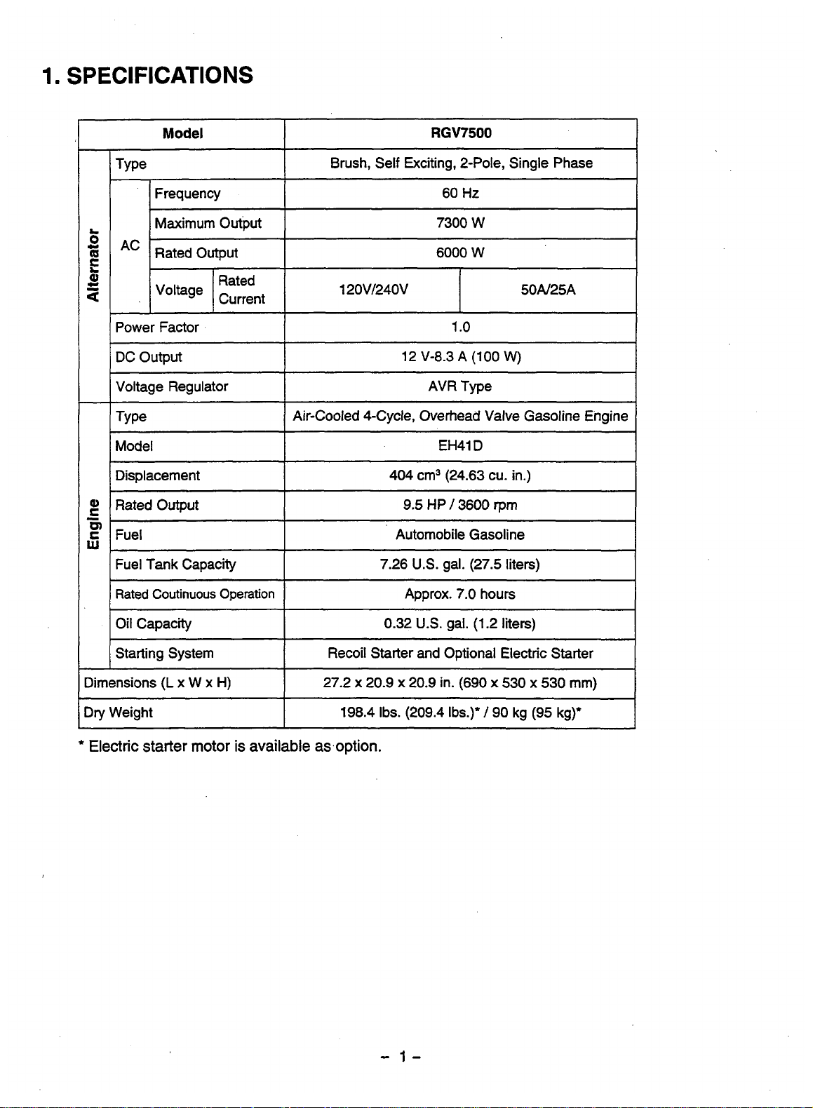
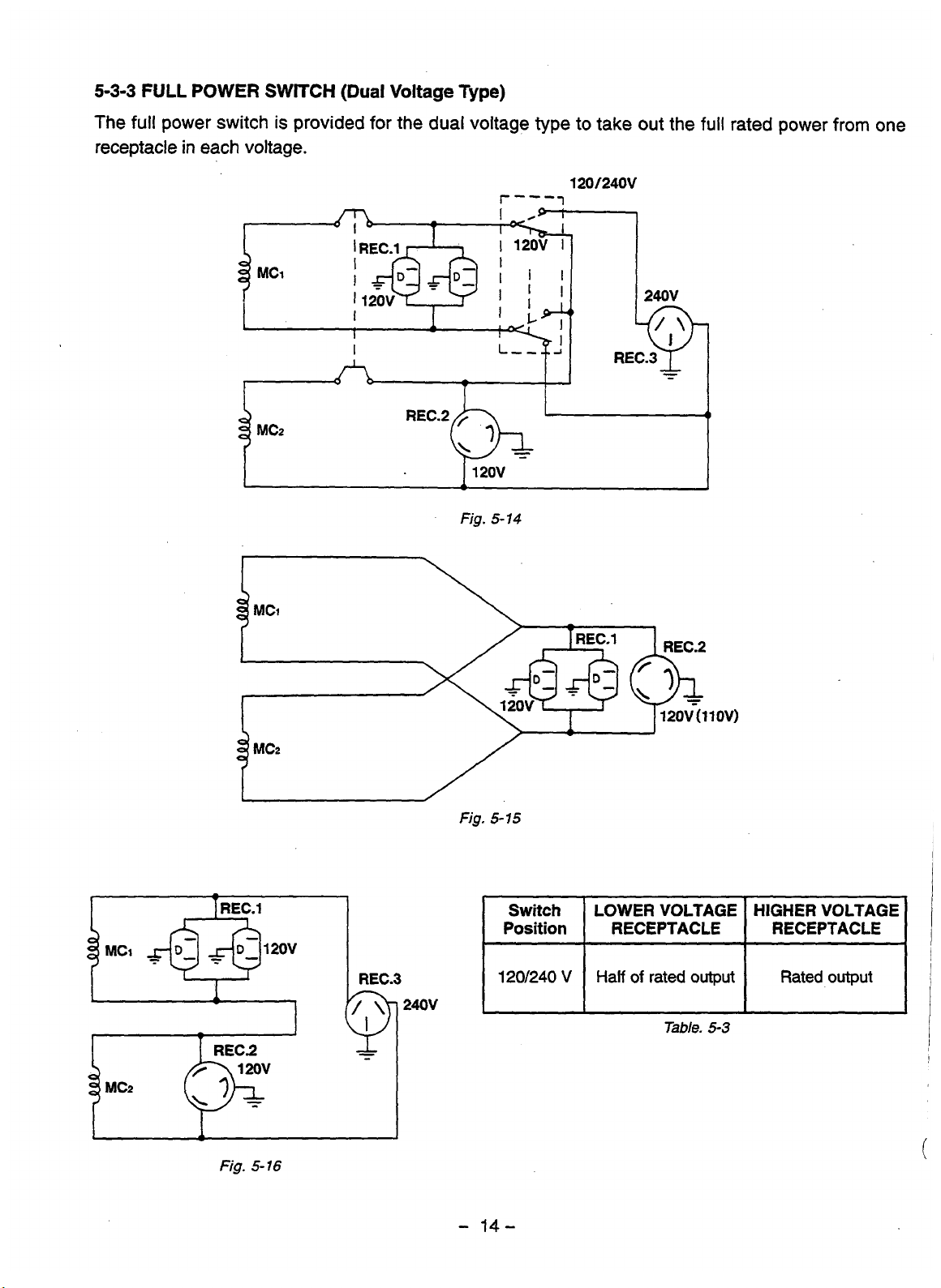
Specifications and Main Features
Model: RGV7500
Type: Two Pole, Single Phase Spin Generator Self Exciting, Brush Set.
Frequency: 60 HZ.
Maximum Output: Maximum Potential Output Voltage is 7300 Watts.
Rated Output: 6000 Watts.
Voltage Rating: 120V with 50A & 240V with 25A.
Power Factor: 1.0.
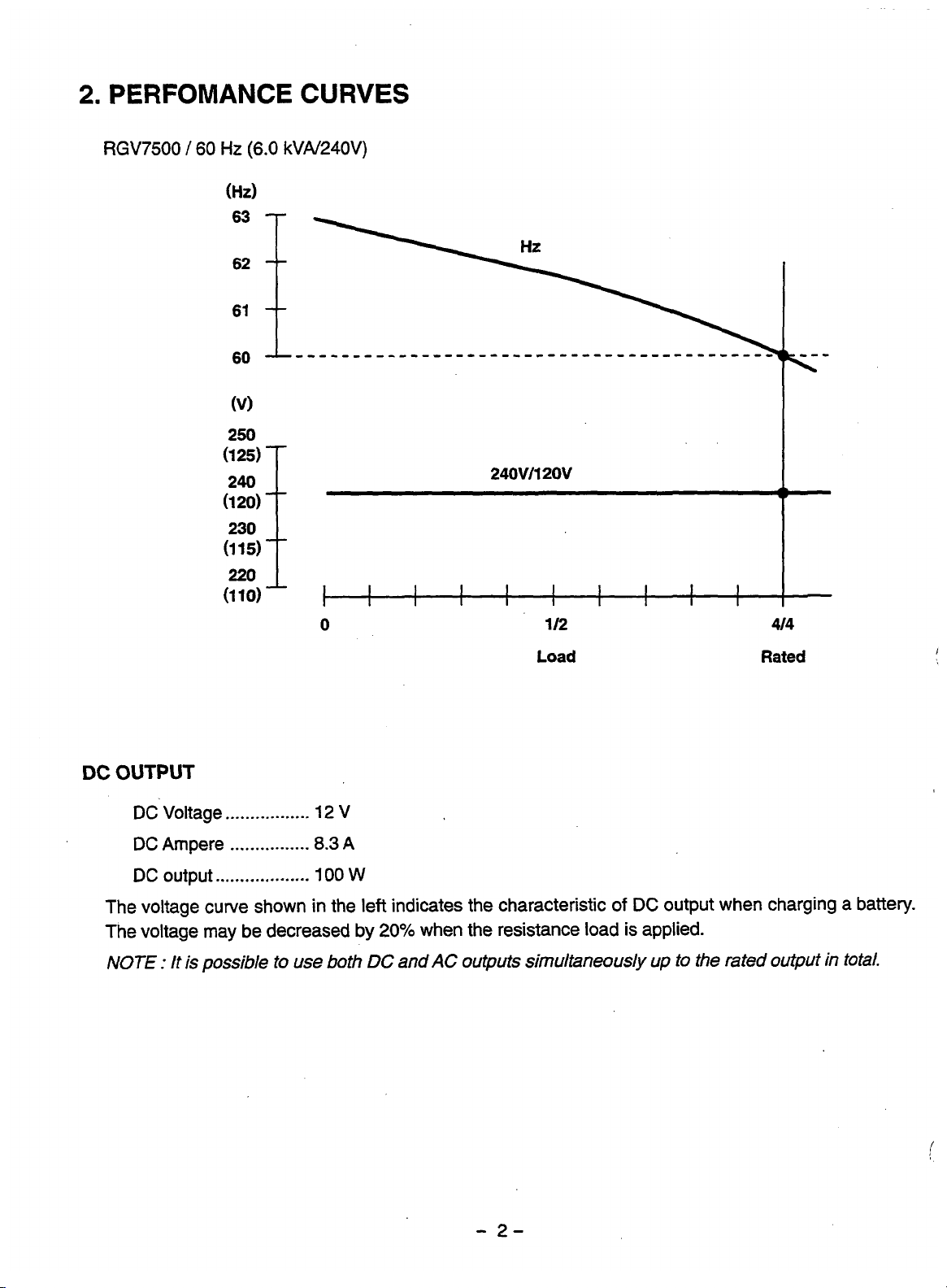
DC Output: Power Supply for 12V and 8.3 A gives an average output of 100 Watts.
Voltage Regulator: AVR type.
Type: Air Cooled Overhead Valve 4 cycle gasoline engine.
Engine Model: EH41D.
Displacement: 404 cm³ which is equivalent to 24.63 cubic inches.
Rated Engine Output: 9.5hp at 3600rpm.
Fuel: Automotive gasoline.
Fuel Tank Capacity: 7.26 U.S gallon equivalent to 27.5 liters.
Rated Continuous Operations: Estimated between 6.5 to 7 hours.
Oil Capacity: 0.32 U.S gallon which is equivalent to 1.2 liters.
Starting System: Comes with a recoil starter, an option for electric starter is also available.
Dimensions (L x W x H): 690 mm x 530 mm x 530 mm which is equivalent to 27.2 inches x 20.9 inches x 20.9 inches.
Weight: A dry weight of 198.4 lbs is noted, whereas additionally with an electric starter the weight is 209.4 lbs, which is 90 Kg and additionally with an electric starter is 95 Kg.
Main Features:
- An stable output voltage is produced by the use of an AVR alternator.
- During low oil levels an oil sensor is in place, whom automatically shuts down the engine.
- A large muffler in place along with an air cleaner aids in a quiet operation.
- Spark plugs suppress noise, hence can interfere with a radio frequency.
- A large fuel tank also results in an additional increase in the amount of time over which the system can be operated.
- Furthermore, the tubular frame used, provides additional sturdiness and protection.
- The design remains compact whilst lightweight.
- Stronger protection and greater lifespan thanks to heavy duty motors with a forged steel crankshaft and no-fuse circuit breakers
- Drip proof alternator which makes these types of devices a lot easier to maintain
Frequently Asked Questions
Q: Is it true that the RGV7500 generator will allow you to boost up to 7300 W? What is the maximum output this generator can reach?
A: The maximum output of the RGV7500 generator is 7300 W.
Q: And what can you tell me about the type of engine which the RGV7500 has?
A: In this case the generator uses an air cooled 4 cycle overhead valve gasoline engine model EH41D.
Q: Does it have a time span in which the generator can continuously run?
A: Roughly around 7.0 hours of continuous operation
Q: And the RGV7500 generator, what is the fuel tank capacity of this generator?
A: The fuel tank capacity is 7.26 U.S. gallons 27.5 liters.
Q: Can you inform me whether this generator has oil sensors?
A: Oil sensors have been fitted in the RGV7500 generator, and it automatically cuts off the engine when the oil goes below a certain level.
Q: ‘How much does the RGV7500 generator weigh?’
A: Its dry weight is 198.4 lb. (209.4 lb. with the electric starter)
Q: ‘Would this generator run both AC and DC outputs at the same time?’
A: Yes, the RGV7500 is designed in such a manner to run both AC and DC outputs simultaneously, upto the rated total output.
Q: ‘What is the measurements of the RGV7500 range?’
A: The measurements of RGV7500 range are 27.2 x 20.9 x 20.9 inches (690 x 530 x 530 mm).
Q: ‘Would you please tell me power factor for RGV7500?’
A: Power factor for RGV7500 is 1.0.
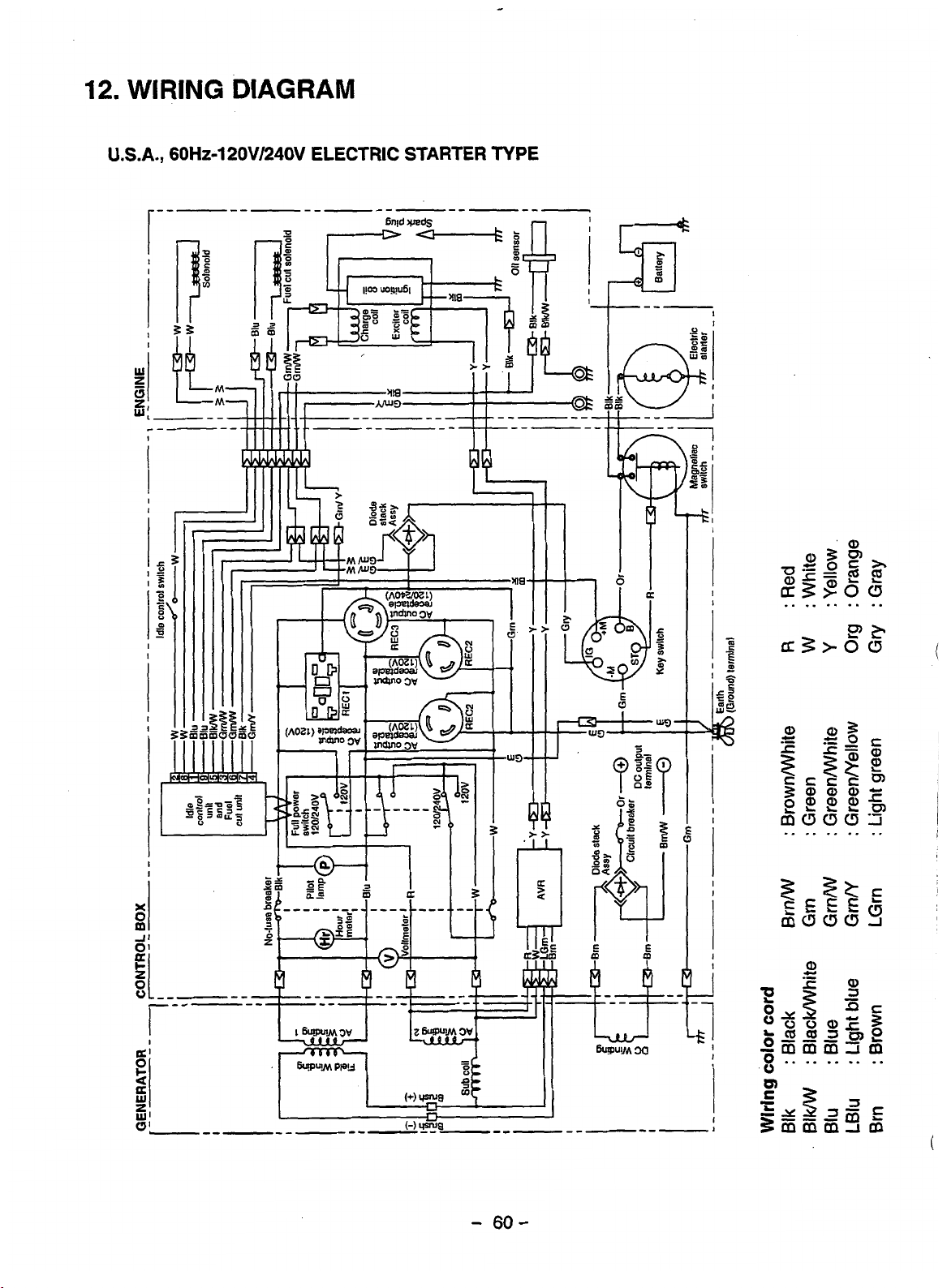
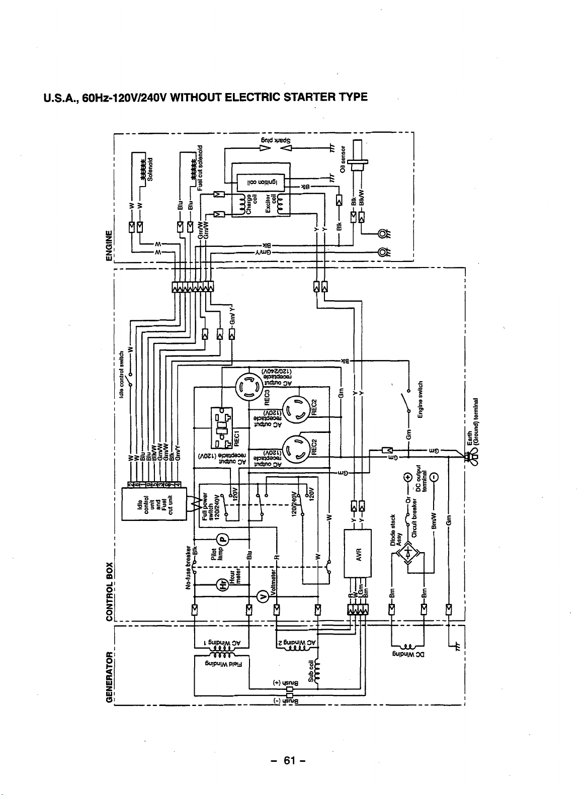
User Manual
SPECIFICATIONS
2. PERFOMANCE CURVES
FEATURES
AVR ALTERNATOR
OIL SENSOR
QUIET OPERATION
NO RADIO NOISE
LARGE FUEL TANK
RUGGED TUBULAR FRAME
MINIMAL MAINTENANCE
LONG-LIFE DURABILITY
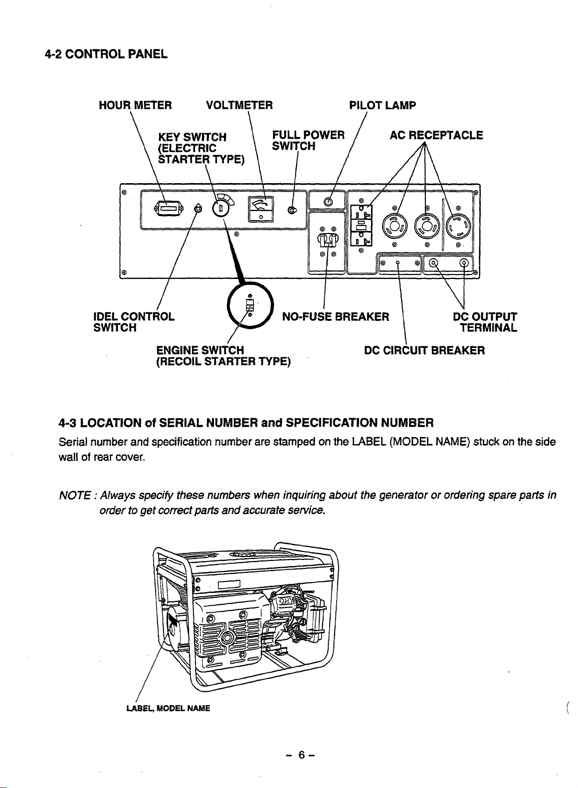
CONTROL PANEL
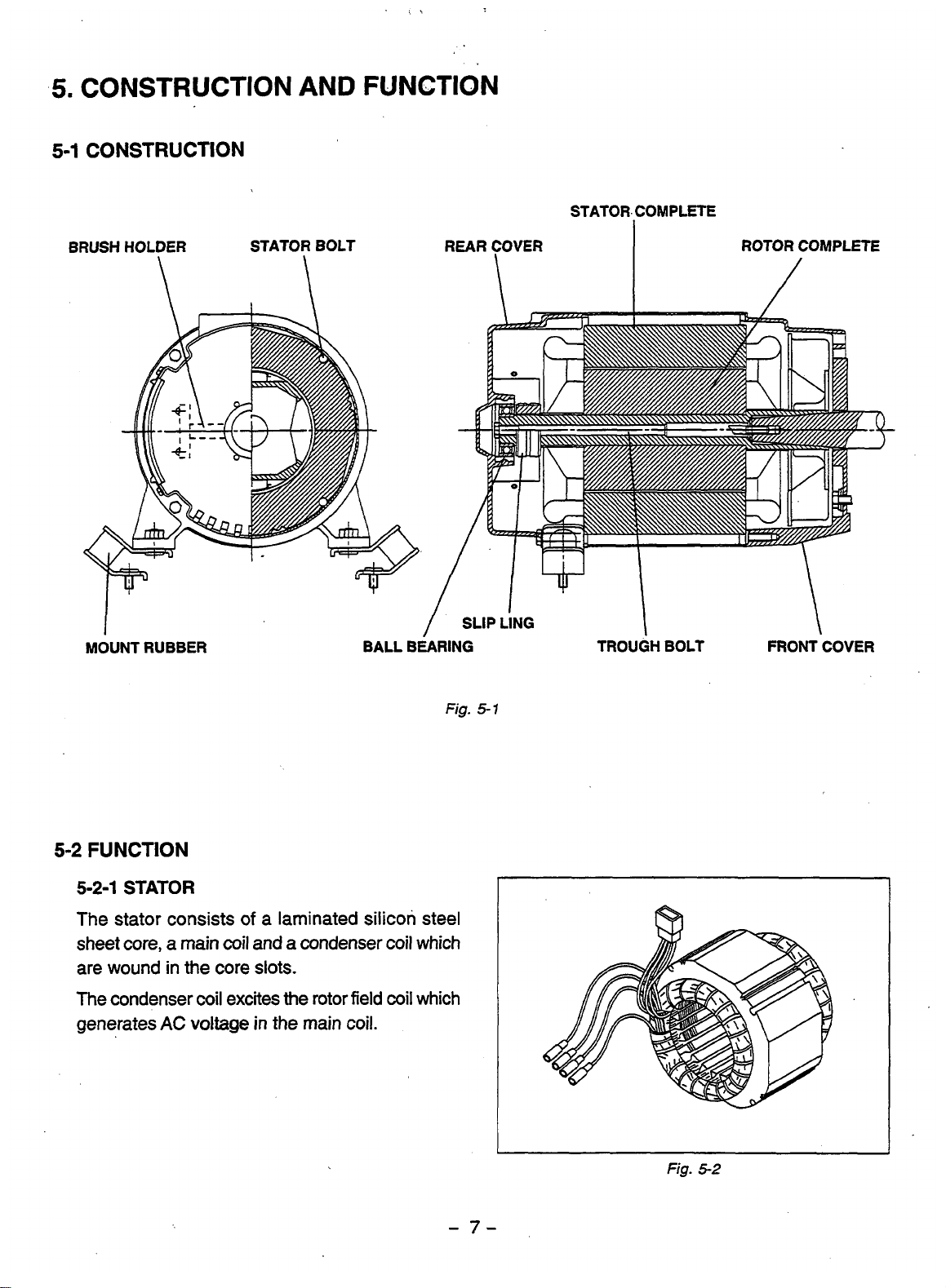
5. CONSTRUCTION AND FUNCTION
CONSTRUCTION
FUNCTION


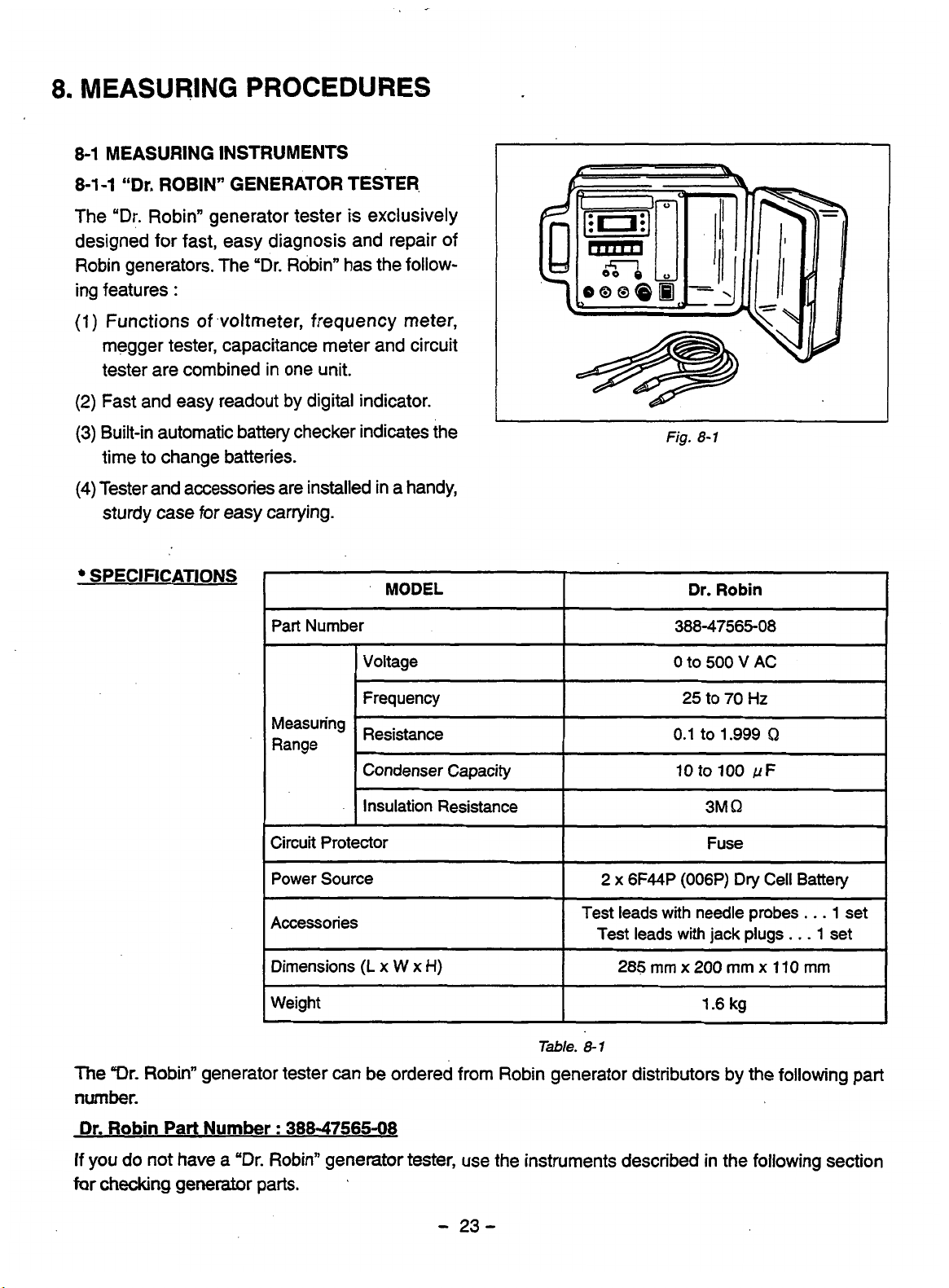
MEASURING INSTRUMENTS


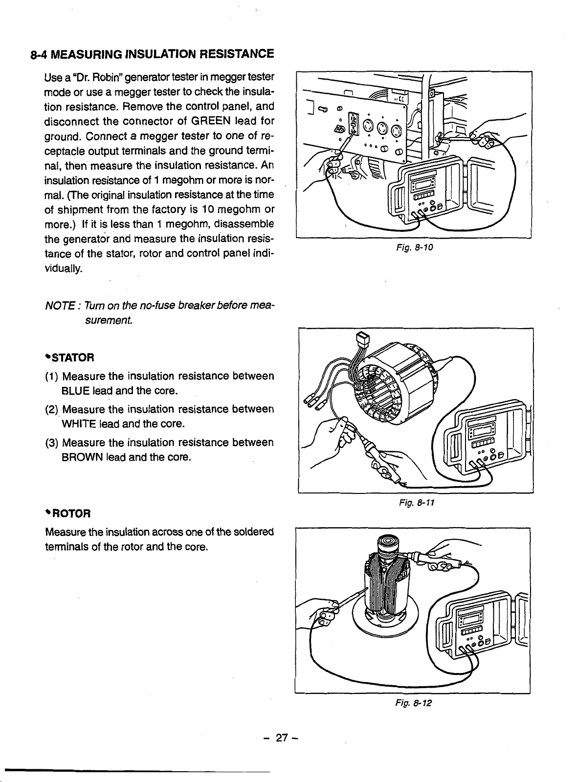
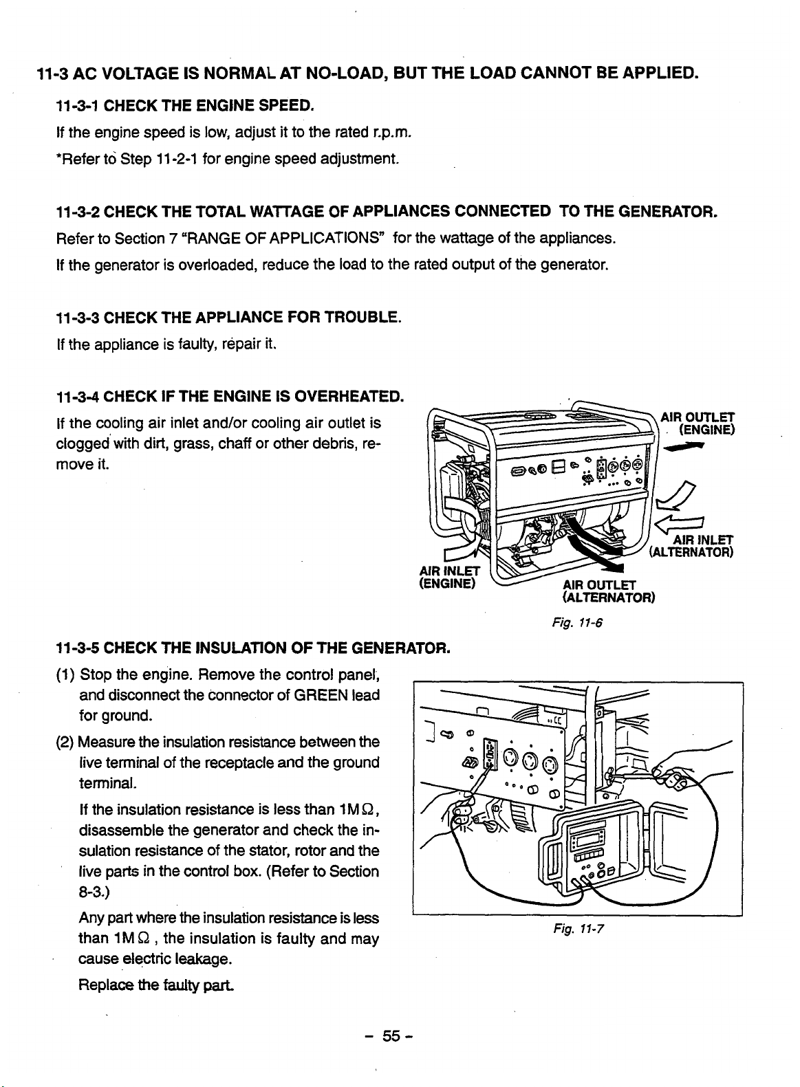
MEASURING INSULATION RESISTANCE

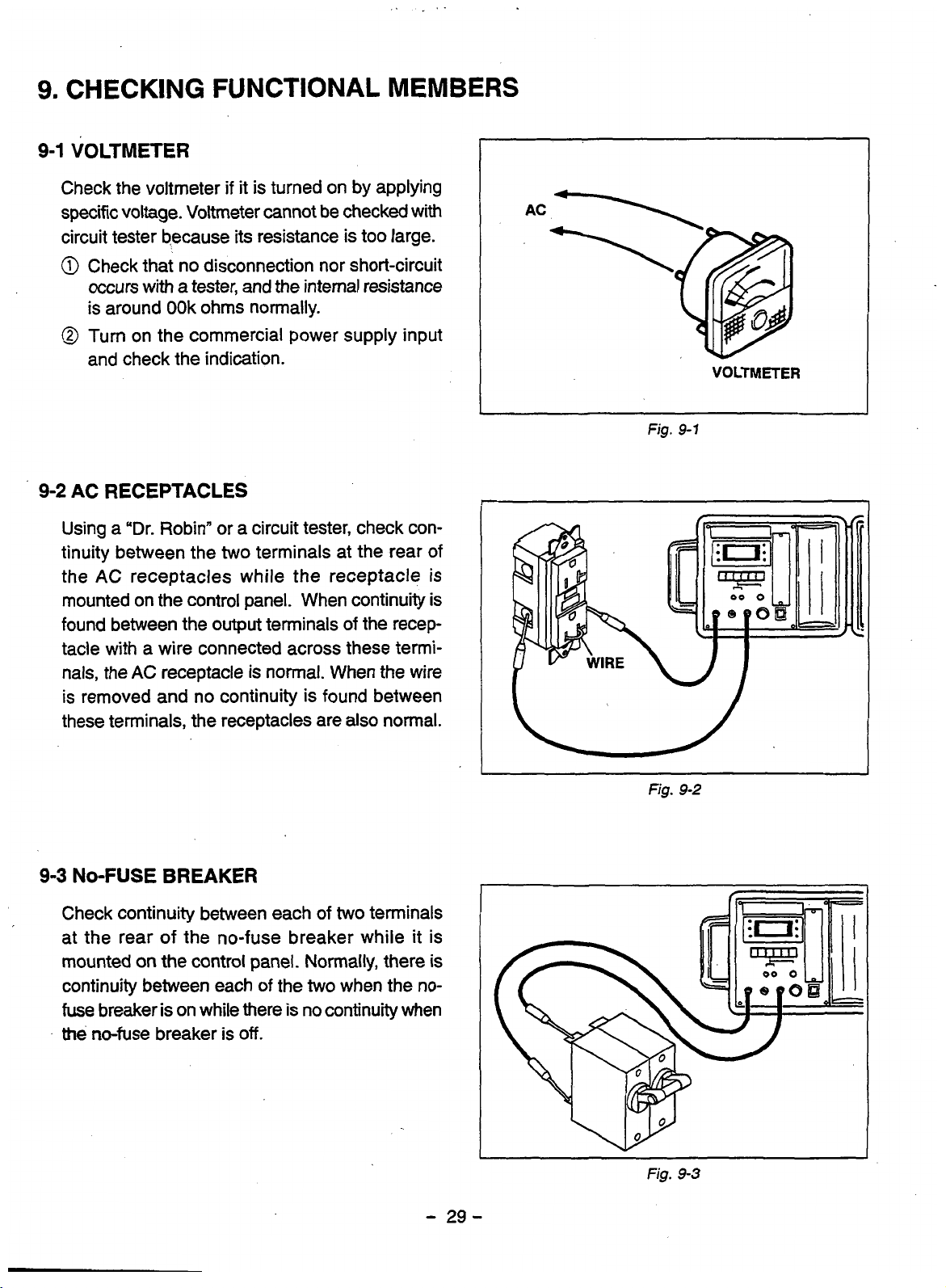
VOLTMETER
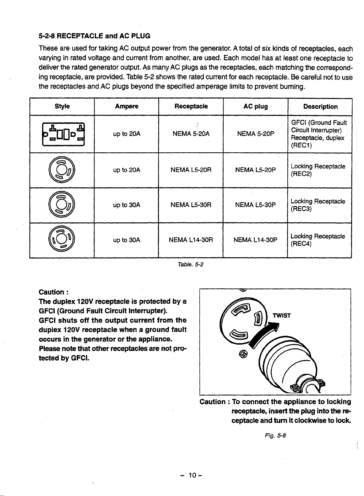
AC RECEPTACLES

STATOR

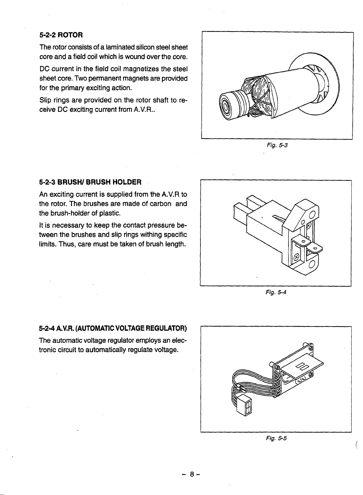
BRUSH


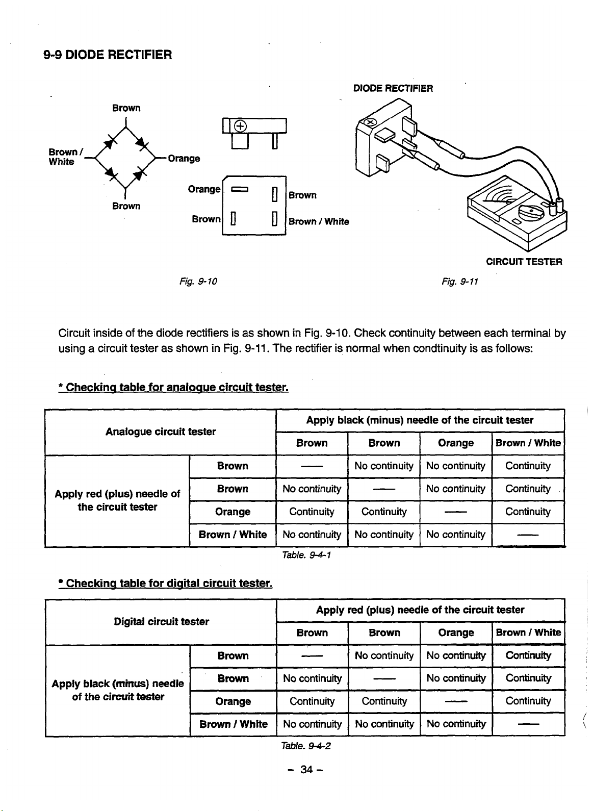
DIODE RECTIFIER


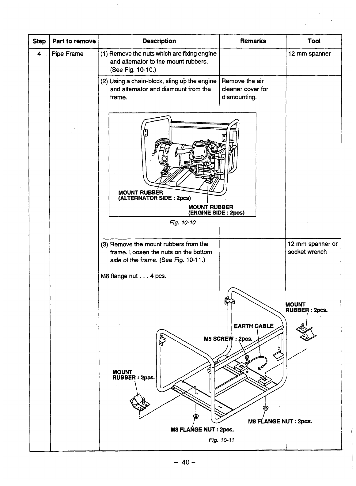
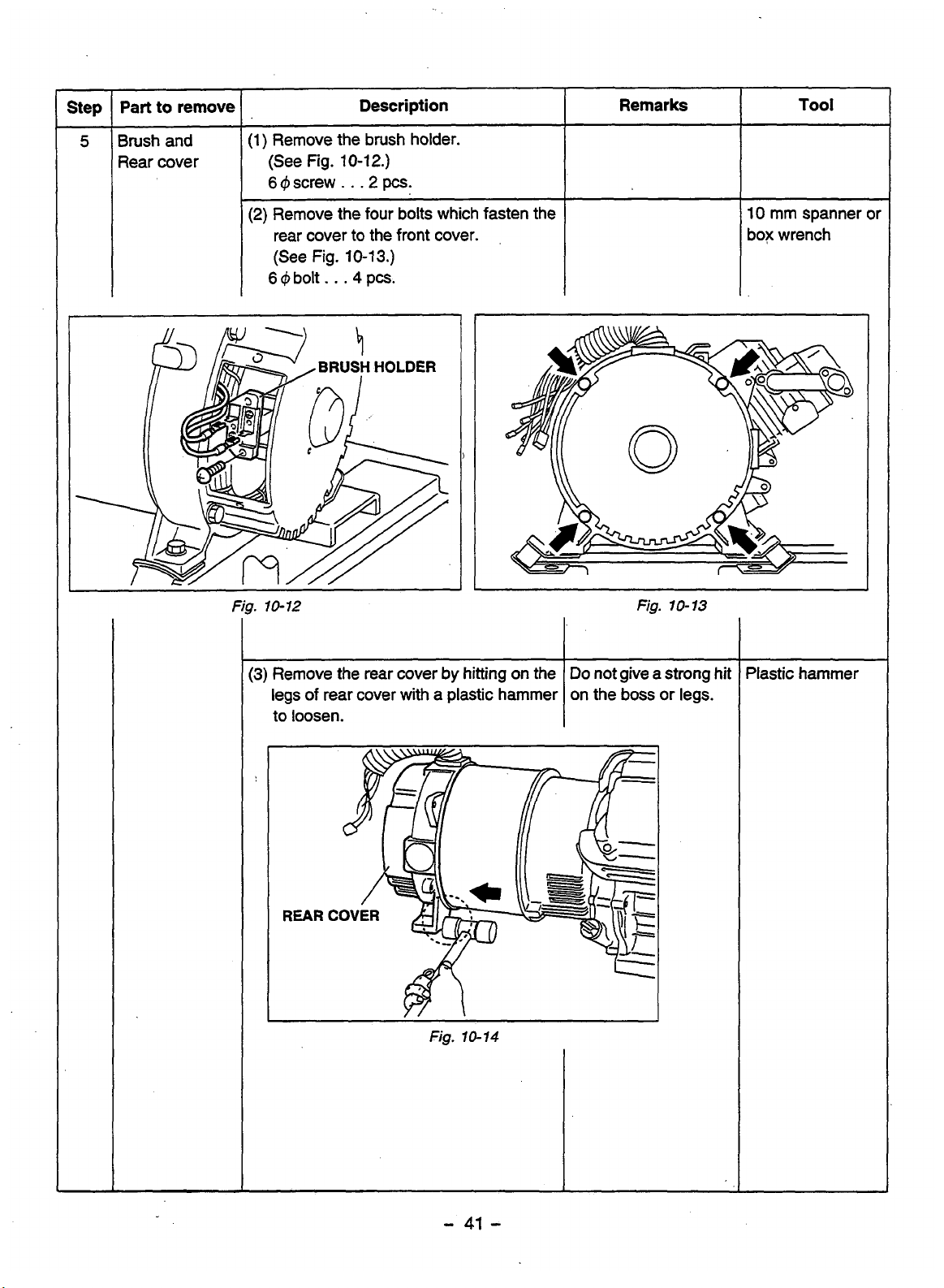
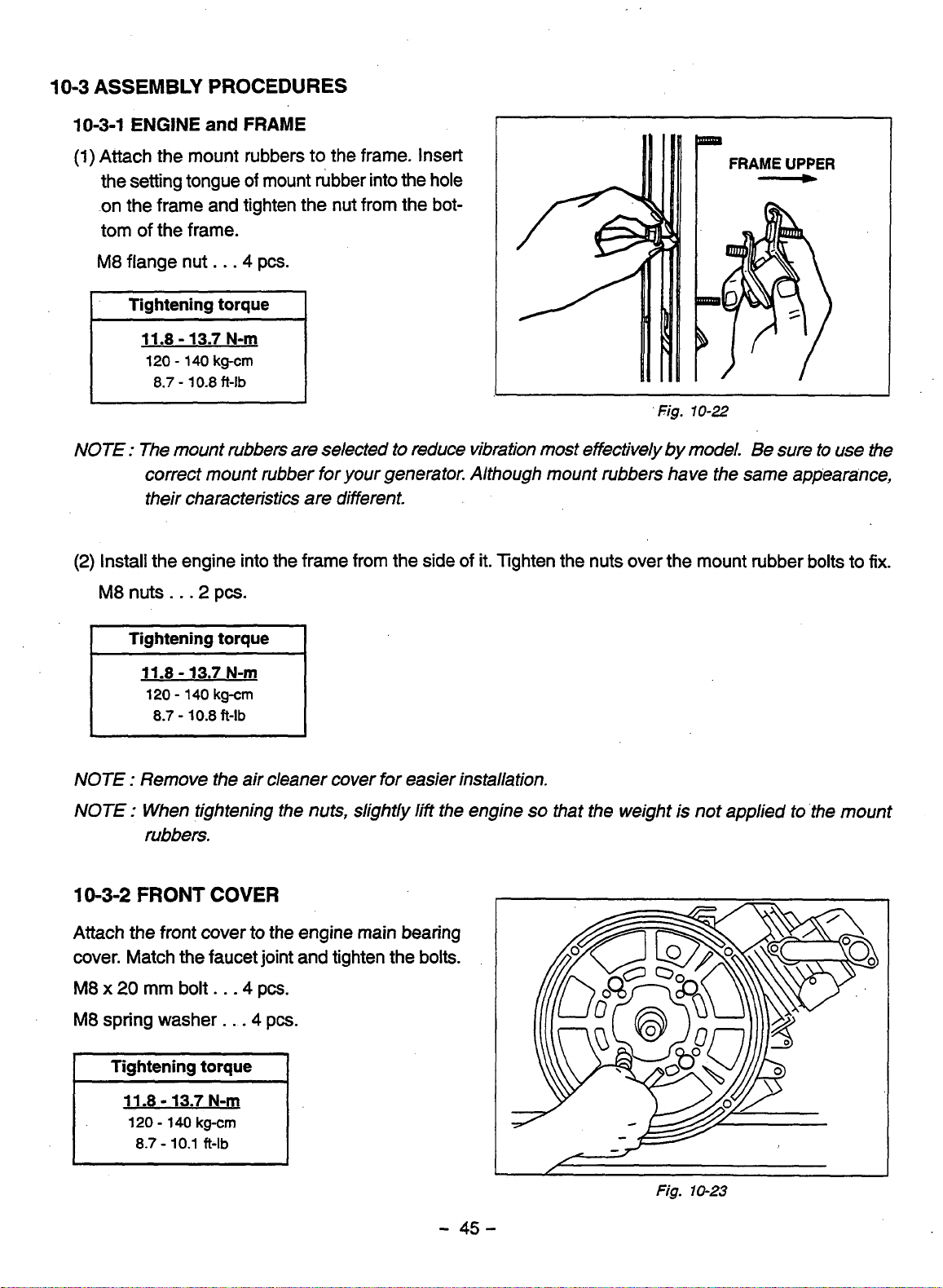
DISASSEMBLY AND ASSEMBLY


 Loading...