

Page 1

SERVICE
MANUAL
Models
RGV2800, RGV4100,
RGV6100
Generators
PUB-GS1277
Rev. 1/04
Page 2

CONTENTS
Section Title Page
1. SPECIFICATIONS....................................................................................................... 1
2. PERFOMANCE CURVES ........................................................................................... 3
3. FEATURES..................................................................................................................5
3-1 BRUSHLESS ALTERNATOR................................................................................5
3-2 CONDENSER TYPE VOLTAGE REGULATOR .................................................... 5
3-3 OIL SENSOR ........................................................................................................5
3-4 QUIET OPERATION ............................................................................................. 5
3-5 NO RADIO NOISE ................................................................................................ 5
3-6 LARGE FUEL TANK..............................................................................................5
3-7 RUGGED TUBULAR FRAME ...............................................................................5
3-8 COMPACT AND LIGHT WEIGHT .........................................................................5
3-9 MINIMAL MAINTENANCE .................................................................................... 6
3-10 LONG-LIFE DURABILITY ...................................................................................6
4. GENERAL DESCRIPTION..........................................................................................7
4-1 EXTERNAL VIEW ................................................................................................. 7
4-2 CONTROL PANEL ................................................................................................ 8
4-3 LOCATION of SERIAL NUMBER and SPECIFICATION NUMBER...................... 9
5. CONSTRUCTION AND FUNCTION .........................................................................10
5-1CONSTRUCTION ................................................................................................ 10
5-2 FUNCTION..........................................................................................................10
5-3 GENERATOR OPERATION ................................................................................16
5-4 OIL SENSOR ......................................................................................................19
6. SAFETY PRECAUTIONS .........................................................................................22
7. RANGE OF APPLICATIONS .................................................................................... 23
8. MEASURING PROCEDURES ..................................................................................26
8-1 MEASURING INSTRUMENTS ........................................................................... 26
8-2 AC OUTPUT MEASURING................................................................................. 29
8-3 DC OUTPUT MEASURING.................................................................................29
8-4 MEASURING INSULATION RESISTANCE ........................................................ 30
9. CHECKING FUNCTIONAL MEMBERS.................................................................... 32
9-1 VOLTMETER.......................................................................................................32
9-2 AC RECEPT ACLES ............................................................................................ 32
9-3 No-FUSE BREAKER........................................................................................... 32
Page 3

Section Title Page
9-4 STATOR .............................................................................................................. 33
9-5 ROTOR ASSEMBLY ........................................................................................... 34
9-6 CONDENSER ..................................................................................................... 34
9-7 DIODE RECTIFIER ............................................................................................. 35
9-8 OIL SENSOR ...................................................................................................... 36
10.DISASSEMBLY AND ASSEMBLY ........................................................................... 37
10-1PREPARATION and PRECAUTIONS ................................................................ 37
10-2 DISASSEMBLY PROCEDURES ....................................................................... 37
10-3 ASSEMBLY PROCEDURES ............................................................................. 38
10-4 CHECKING, DISASSEMBLY and REASSEMBLY of the FRONT PANEL ........ 46
11. TROUBLESHOOTING ............................................................................................ 51
11-1 NO AC OUTPUT................................................................................................ 53
11-2 AC VOLTAGE IS TOO HIGH OR TOO LOW ..................................................... 55
11-3 AC VOLTAGE IS NORMAL AT NO-LOAD,
BUT THE LOAD CANNOT BE APPLIED..................................... 56
11-4 NO DC OUTPUT ............................................................................................... 57
11-5 IDLE CONTROL(OPTIONAL EQUIPMENT) ..................................................... 58
12. WIRING DIAGRAM ................................................................................................. 61
Troubleshooting Manual RGV4101/RGV6101............................................................ 64
1. SPECIFCATIONS..................................................................................................... 64
2. GENERATOR TROUBLE SHOOTING...................................................................... 65
2-1 No AC output...................................................................................................... 65
2-2 AC voltage is too high or too low........................................................................ 67
2-3 AC voltage is normal at No-load, but the load cannot be applied....................... 68
2-4 No DC output...................................................................................................... 69
2-5 Idle control (Optional equipment)........................................................................ 71
3. RANGE OF APPLICATIONS................................................................................... 74
4. WIRING DIAGRAM................................................................................................... 77
NOTE : As for the servicing information on engine protion, please refer to the EH17-2,
EH25-2 and EH34 engine service manual.
Page 4
1. SPECIFICATIONS
ledoM0082VGR0014VGR
epyT esahPelgniS,eloP-2,gniticxEfleS,sselhsurB
CA
ycneuqerF zH06
tuptuOmumixaMW0082W0014
tuptuOdetaRW0032W0063
egatloV
detaR
tnerruC
V021A2.91V021A0.03
V042/V021A6.9/A2.91V042/V021A0.51/A0.03
rotcaFrewoP 0.1
tuptuOCD )W001(A3.8-V21
rotalugeRegatloV epyTresnednoC
epyT enignEenilosaGevlaVdaehrevO,elcyC-4delooC-riA
ledoMD2-71HED2-52HE
tnemecalpsiDmc271
3
).ni.uc05.01(mc152
3
).ni.uc23.51(
tuptuOdetaRmpr0063/PH0.4mpr0063/PH4.6
leuF enilosaGelibomotuA
yticapaCknaTleuF)sretil21(.lag.S.U71.3 )sretil6.61(.lag.S.U83.4
noitarepOsuounituoCdetaR
sruoh0.9sruoh0.7
yticapaCliO)sretil56.0(.lag.S.U71.0 )sretil0.1(.lag.S.U63.0
metsySgnitratSretratSlioceR retratScirtcelElanoitpOdnaretratSlioceR
)HxWxL(snoisnemiD )mm394x514x065(.ni4.91x3.61x0.22 )mm255x034x026(.ni7.12x9.61x4.42
thgieWyrD)gk84(.sbl601 *)gk5.36(gk06/*).sbl041(.sbl231
ENGINE
ALTERNATOR
* Electric starter motor is available as option.
- 1 -
Page 5
ENGINE
ledoM0016VGR
epyT esahPelgniS,eloP-2,gniticxEfleS,sselhsurB
CA
ycneuqerFzH06
tuptuOmumixaMW0085
tuptuOdetaRW0084
egatloV
detaR
tnerruC
V042/V021A02/A04
rotcaFrewoP0.1
tuptuOCD)W001(A3.8-V21
rotalugeRegatloVepyTresnednoC
epyT enignEenilosaGevlaVdaehrevO,elcyC-4delooC-riA
ledoMD43HE
tnemecalpsiDmc833
3
).ni.uc36.02(
tuptuOdetaRmpr0063/PH0.8
leuFenilosaGelibomotuA
yticapaCknaTleuF)sretil5.12(.lag.S.U76.5
noitarepOsuounituoCdetaR
sruoh0.7
yticapaCliO)sretil2.1(.lag.S.U23.0
metsySgnitratS retratScirtcelElanoitpOdnaretratSlioceR
)HxWxL(snoisnemiD )mm036x074x086(.ni8.42x5.81x8.62
thgieWyrD *)gk5.18(gk87/*).sbl081(.sbl271
ALTERNATOR
* Electric starter motor is available as option.
- 2 -
Page 6
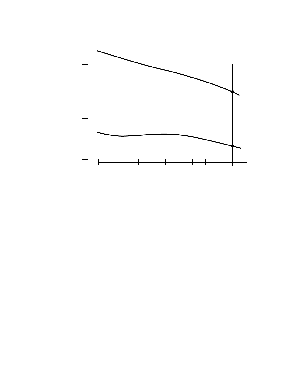
2. PERFOMANCE CURVES
(Hz)
63
250
(
125
240
(
120
230
(
115
220
(
110
62
61
60
(V)
Hz
)
230V/115V
)
)
)
0 1/2 4/4
Load Rated
- 3 -
Page 7

DC OUTPUT
DC Voltage................. 12 V
DC Ampere ................ 8.3 A
DC output................... 100 W
The voltage curve shown in the left indicates the characteristic of DC output when charging a battery.
The voltage may be decreased by 20% when the resistance load is applied.
NOTE : It is possible to use both DC and AC outputs simultaneously up to the rated output in total.
- 4 -
Page 8

3. FEATURES
3-1 BRUSHLESS ALTERNATOR
Newly developed brushless alternator eliminates troublesome brush maintenance.
3-2 CONDENSER TYPE VOLTAGE REGULATOR
A trouble free condenser type voltage regulator ensures a stable voltage under all working conditions.
3-3 OIL SENSOR
Oil sensor automatically shuts off the engine whenever the oil level falls down below the lower limit to
protect the engine from seizure.
3-4 QUIET OPERATION
Robin RGV series generator delivers a quiet operation with :
* A large super silent muffler.
* A quiet 4-stroke Robin Rro OHV engine.
* A silent cyclone air cleaner.
3-5 NO RADIO NOISE
Noise suppressor spark plug is equipped standard to prevent radio frequency interference.
3-6 LARGE FUEL TANK
The large fuel tank allows more than 7 to 10 hours of continuous operation which is sufficient for a half
day or one day work without refueling.
3-7 RUGGED TUBULAR FRAME
Full cradle type rugged tubuler frame protects the generator all around.
3-8 COMPACT AND LIGHT WEIGHT
Newly developed brushless alternator enabled the RGV generators to be very compact in size and light
in weight.
- 5 -
Page 9

3-9 MINIMAL MAINTENANCE
* A brushless alternator release the operator from periodical brush maintenance.
* A trouble free condenser type voltage regulator.
* A drip-proof alternator design.
* No-fuse circuit breakers.
* An electronic pointless ignition system.
* A dust-proof cyclone air cleaner.
3-10 LONG-LIFE DURABILITY
The heavy-duty 4 stroke Robin Rro OHV engine and virtually maintenance-free brushless alternator
ensure greater durability with :
* A brushless alternator with a condenser voltage regulator.
* Full rubber mount in a sturdy tubular frame.
* A forged steel crankshaft supported by two main ball bearings.
* A pointless electronic ignition system.
* A cast-iron cylinder liner.
* A forged aluminum connecting rod.
- 6 -
Page 10
4. GENERAL DESCRIPTION
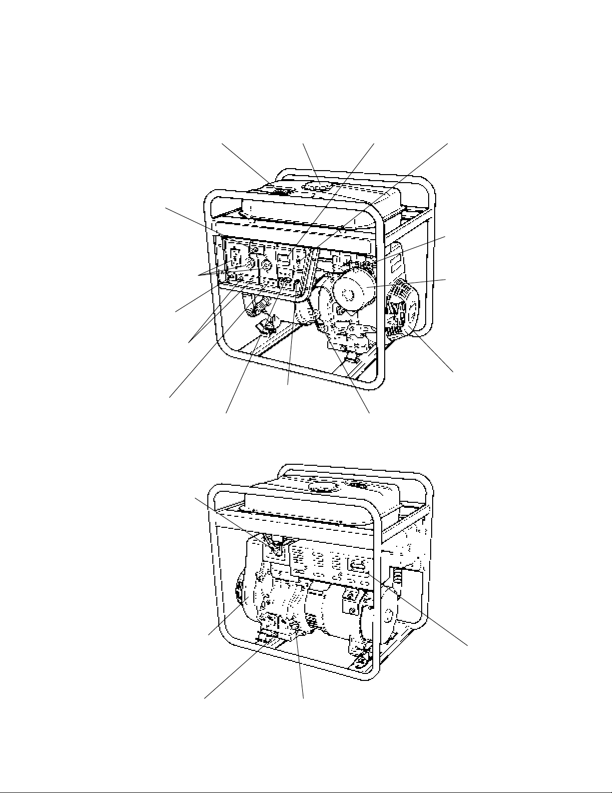
4-1 EXTERNAL VIEW
FUEL GAUGE VOLTMETER
FULL POWER
SWITCH
AC
RECEPTACLE
EARTH
TERMINAL
DC OUTPUT
TERMINAL
DC CIRCUIT
BREAKER
NO-FUSE
BREAKER
TANK CAP
IDEL CONTROL
SWITCH
ENGINE SWITCH
CHOKE KNOB
AIR CLEANER
RECOIL STARTER
OIL SENSOR
SPARK PLUG
ENGINE
EMISSION LABEL
OIL DRAIN PLUG OILGAUGE (OIL FILLER)
- 7 -
MUFFLER
Page 11
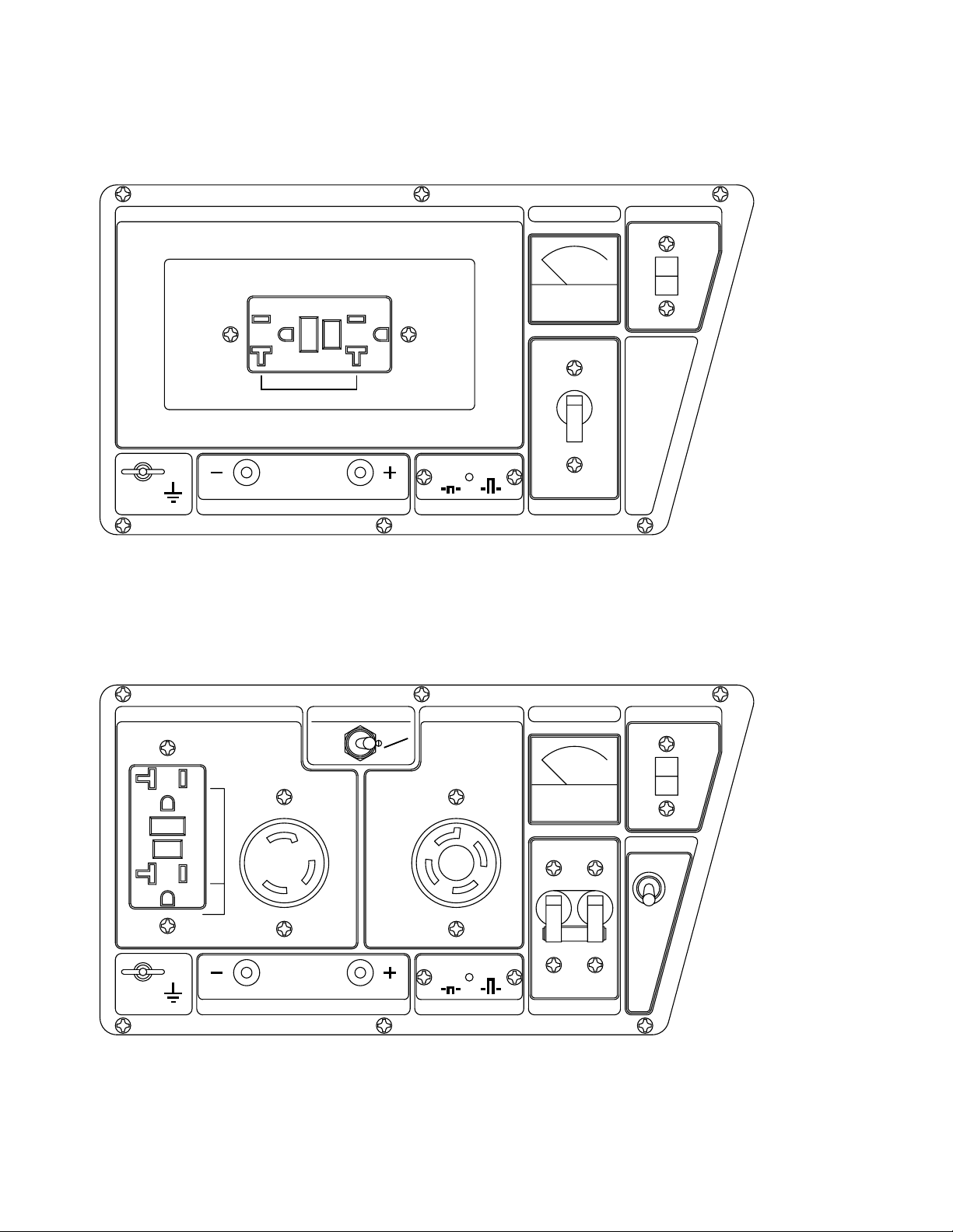
4-2 CONTROL PANEL
* RGV2800 : U.S.A., 60Hz-120V [NEMA RECEPTACLE]
AC OUTPUT
RESET
TEST
TEST
RESET
V METER
AC MAX 20A
DC 12V-8.3A
BATTERY CHARGE ONLY
DC OUTPUT
ON OFF
DC BREAKER
AC BREAKER
* RGV4100 : U.S.A., 60Hz-120V/240V [NEMA RECEPTACLE]
ENGINE SWITCH
ON
OFF
AC 120V AC 120V / 240V
RESET
RESET
TEST
TEST
AC MAX 20A AC MAX 20AAC MAX 30A
30A
125V
DC 12V-8.3A
BATTERY CHARGE ONLY
DC OUTPUT DC BREAKER
FULL POWER SWITCH
120V
120V
240V
20A
ON OFF
V METER
ON
OFF
AC BREAKER
ENGINE SWITCH
ON
OFF
IDEL CONTROL
ON
OFF
- 8 -
Page 12
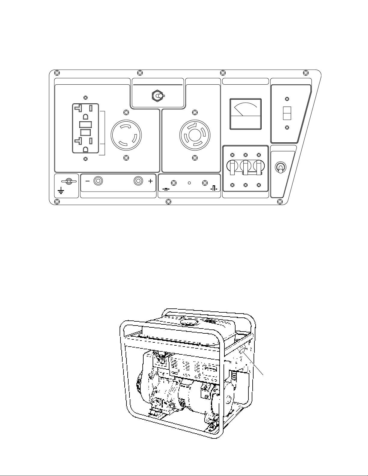
* RGV6100 : U.S.A., 60Hz-120V/240V [NEMA RECEPTACLE]
AC 120V AC 120V / 240VFULL POWER SWITCH
120V
RESET
RESET
TEST
TEST
AC MAX 20A
BATTERY CHARGE ONLY
30A
150V
AC MAX 30A AC MAX 20A
DC 12V-8.3A
DC OUTPUT
120V
/240V
20A
ON OFF
DC BREAKER
V METER
ON
OFF
AC BREAKER
ENGINE SWITCH
ON
OFF
IDEL CONTROL
ON
OFF
4-3 LOCATION of SERIAL NUMBER and SPECIFICATION NUMBER
Serial number and specification number are stamped on the LABEL (MODEL NAME) stuck on the side
wall of control box.
NOTE : Always specify these numbers when inquiring about the generator or ordering spare parts in
order to get correct parts and accurate service.
LABEL,
MODEL NAME
- 9 -
Page 13
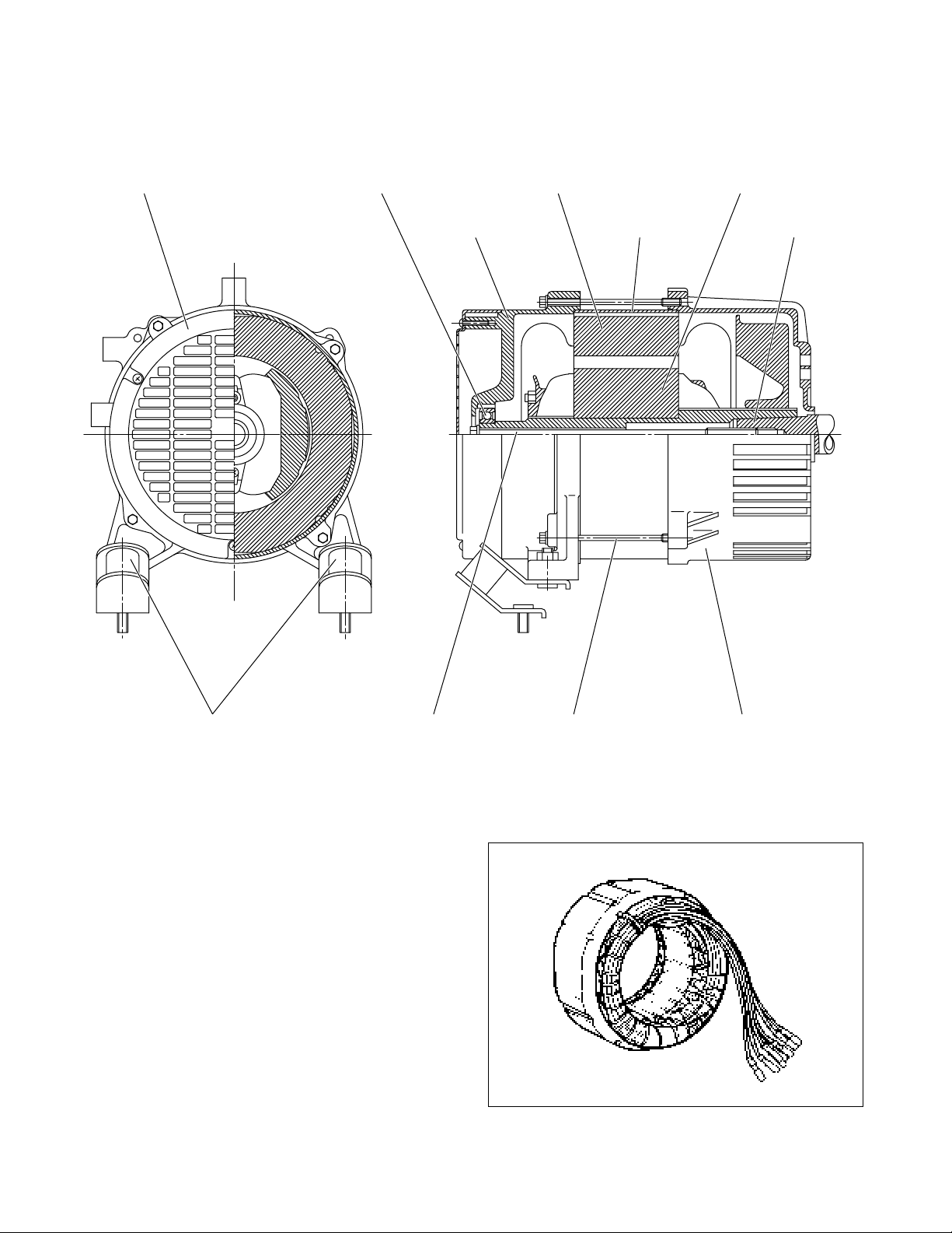
5. CONSTRUCTION AND FUNCTION
5-1 CONSTRUCTION
END COVER
BALL BEARING
STATOR COMPLETE
REAR COVER
STATOR COVER
ROTOR COMPLETE
CRANKSHAFT
THROUGH BOLT COVER BOLT FRONT COVERMOUNT RUBBER
5-2 FUNCTION
5-2-1 STATOR
The stator consists of a laminated silicon steel
sheet core, a main coil and a condenser coil which
are wound in the core slots.
The condenser coil excites the rotor field coil which
generates AC voltage in the main coil.
Fig. 5-1
Fig. 5-2
-
10
-
Page 14
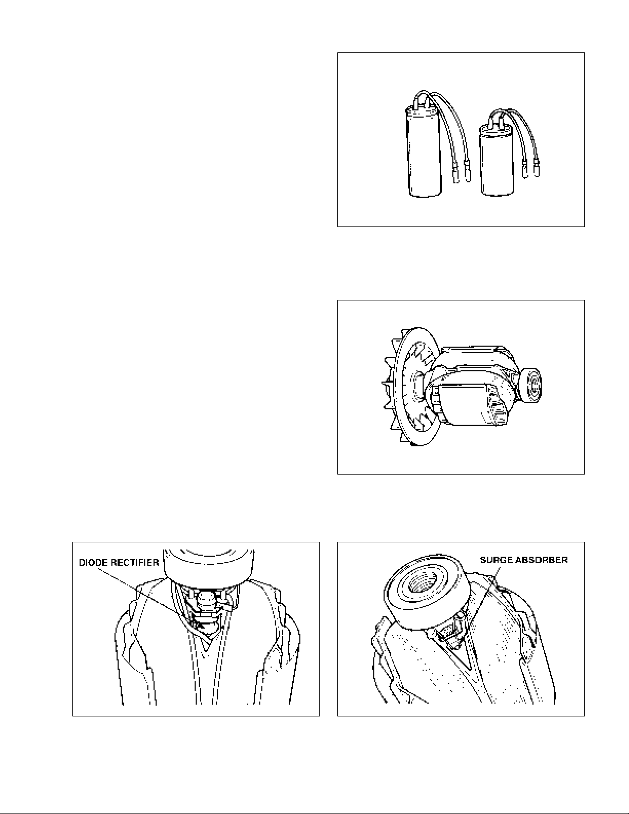
5-2-2 CONDENSER
One or two condensers are installed in the control box and are connected to the condenser coil
of the stator.
These condensers and condenser coil regulate
the output voltage.
5-2-3 ROTOR
The rotor consists of a laminated silicon steel sheet
core and a field coil which is wound over the core.
Fig. 5-3
DC current in the field coil magnetizes the steel
sheet core. T wo permanent magnets are provided
for the primary exciting action.
A diode rectifier and surge absorber is mounted inside of the insulator.
Fig. 5-4
Fig. 5-5BFig. 5-5A
-
11
-
Page 15
5-2-4 NO-FUSE BREAKER
The no-fuse breaker protects the generator from getting damage by overloading or short circuit in the
appliance. Table 5-1 shows the capacity of no-fuse breaker by each spec. and their object of protection.
LEDOMNOITACIFICEPSREKAERBESUF-ONNOITCETORProTCEJBO
0082VGR V021-zH06A02egarepmatuptuolatoT
0014VGR V042/V021-zH06)tnemelE-2,eloP-2(A51egarepmatuptuolatoT
)tnemelE-2,eloP-2(A02egarepmatuptuolatoT
0016VGR V042/V021-zH06
A03elcatpecerA03morftuptuO
Table. 5- 1
5-2-5 DC CIRCUIT BREAKER
The 10 ampere DC circuit breaker mounted on
the control panel protects whole DC circuit from
getting damage by overload or short circuit.
Fig. 5-6
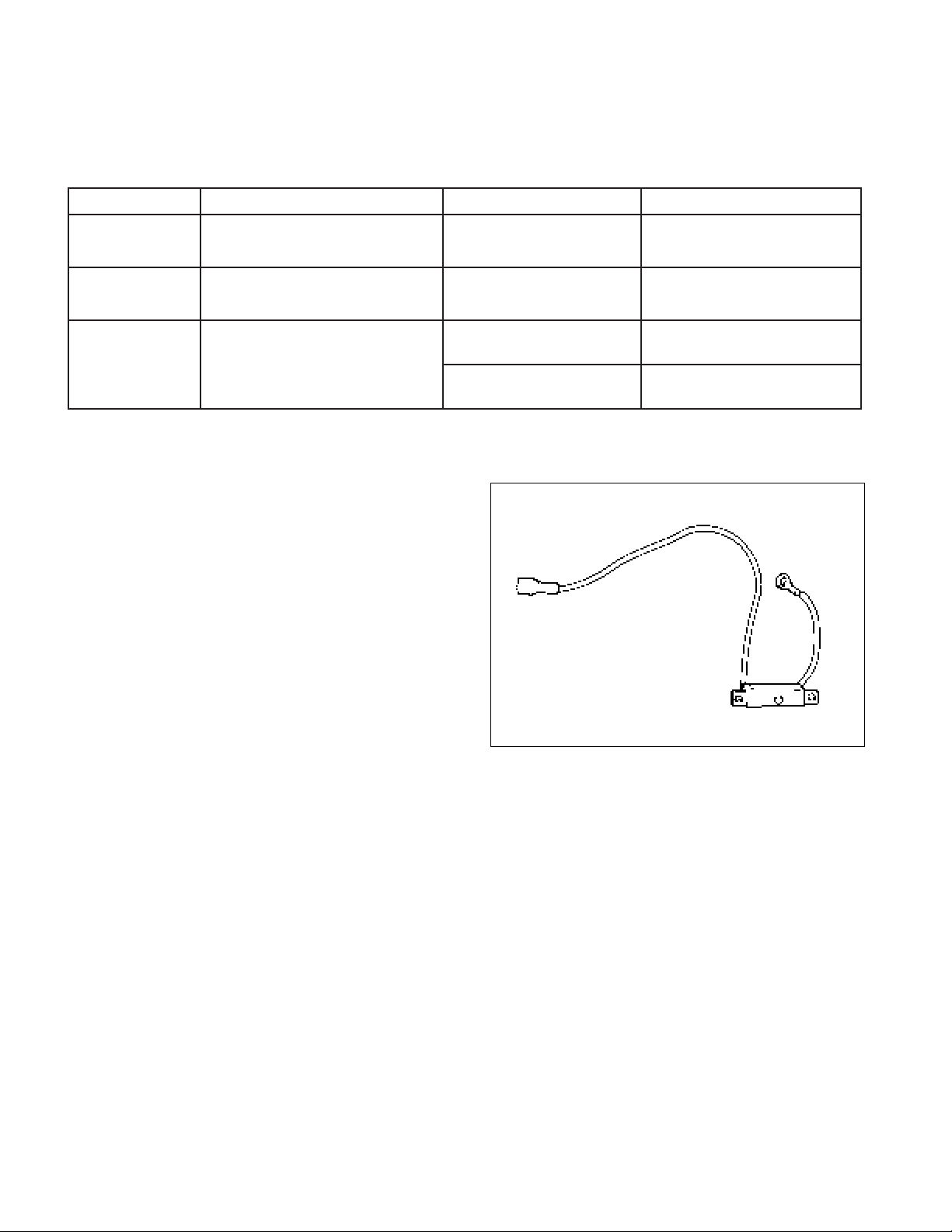
5-2-6 RECEPTACLE and AC PLUG (STD. SPEC.)
These are used for taking AC output power from the generator. A total of six kinds of receptacles, each
varying in rated voltage and current from another, are used. Each model has at least one receptacle to
deliver the rated generator output. As many AC plugs as the receptacles, each matching the corresponding receptacle, are provided. Table 5-2 shows the rated current for each receptacle. Be careful not to use
the receptacles and AC plugs beyond the specified amperage limits to prevent burning.
-
12
-
Page 16
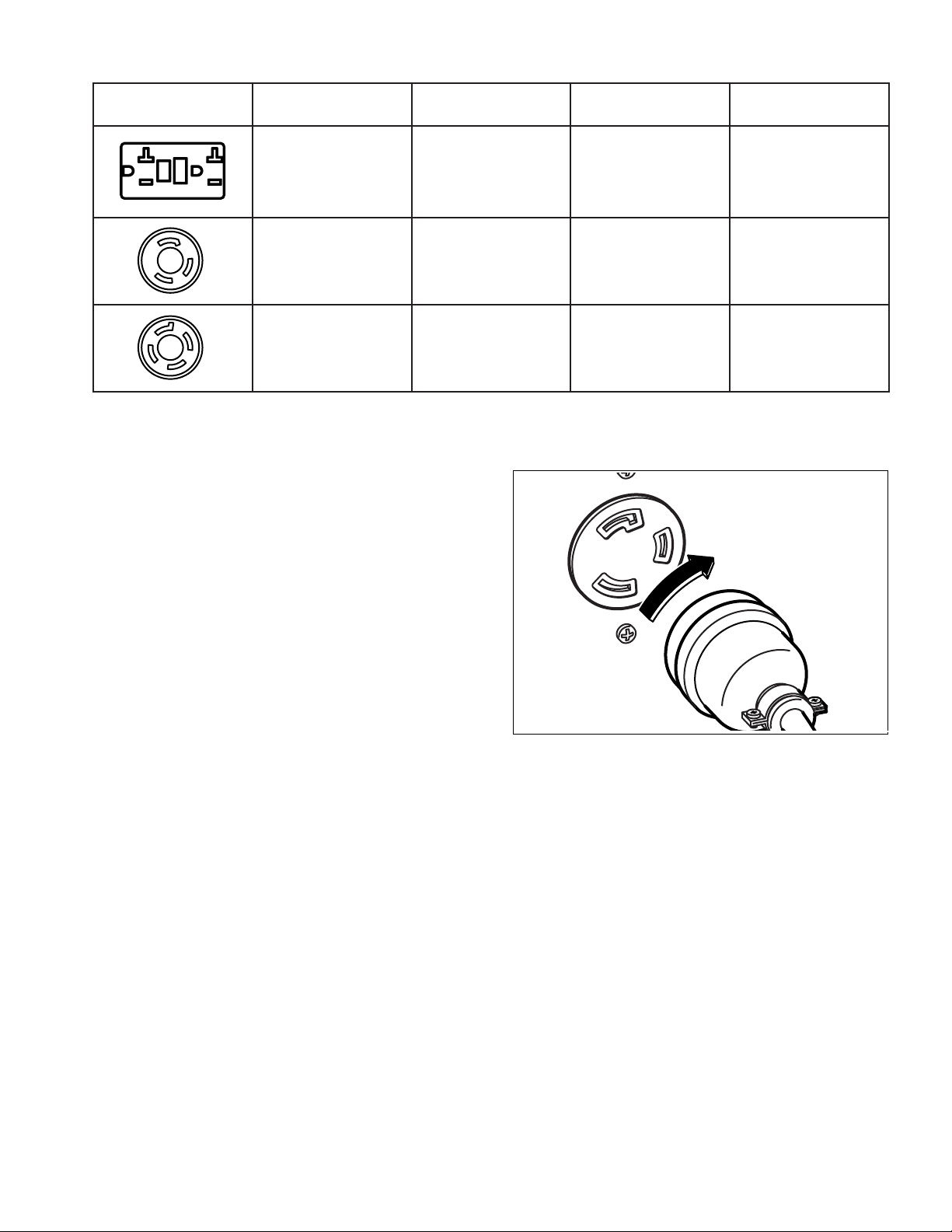
TWIST
elytSerepmAelcatpeceRgulpCAnoitpircseD
A02otpuA02-5AMENP02-5AMEN
tluaFdnuorG(ICFG
)retpurretnItiucriC
xelpud,elcatpeceR
)1CER(
A02otpuR02-41LAMENP02-41LAMEN
A03otpuR03-5LAMENP03-5LAMEN
Table. 5-2
NOTE : If your generator has receptacles pecu-
liar to your country, Table 5-2 does not
apply.
Caution :
The duplex 120V receptacle is protected by a
GFCI (Ground Fault Circuit Interrupter).
GFCI shuts off the output current from the
duplex 120V receptacle when a ground fault
occurs in the generator or the appliance.
Please note that other receptacles are not protected by GFCI.
elcatpeceRgnikcoL
)2CER(
elcatpeceRgnikcoL
)3CER(
Caution : To connect the appliance to locking
receptacle, insert the plug into the receptacle and turn it clockwise to lock.
Fig. 5-8
5-2-7 GFCI RECEPTACLE
After starting the engine, check the GFCI for proper functioning by the following test procedure.
Push yellow TEST button, The red RESET button will pop out exposing the word TRIP. Power is now off
at the outlets protected by the GFCI, indicating that the device is functioning properly.
If TRIP dose not appear when testing, do not use the generator. Call a qualified electrician.
To restore power, push RESET button.
WARNING :
If the RESET button pops out during operation, stop the generator immediately and call a
qualified electrician for checking generator and the appliances.
-
13
-
Page 17
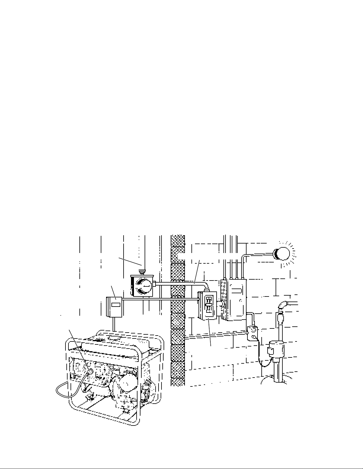
5-2-8 CONNECTING TO DOMESTIC CIRCUITS (HOUSE WIRING)
WARNING :
All Robin generators are a neutral ungrounded type.
If a generator is to be connected to residential or commercial power lines, such as a stand-by
power source during power outage, all connections must be made by a licensed electrician.
Failure in connection may result in death, personal injury , damage to generator, damage to appliances, damage to the building's wiring or fire.
(a) When contnecting a Robin generator to a house wiring, generator output power must be taken from
the 240V-4P receptacle.
(b) Install a transfer switch.
A transfer switch must be installed to transfer the load from the commercial power source to the
generator. This switch is necessary to prevent accidents caused by the recovery from power outage.
Use a transfer switch of the correct capacity . Install transfer switch between the meter and the fuse or
AC breaker box.
Caution : If the neutral wire of house wiring is grounded, be sure to ground the ground terminal of the
generator. Otherwise an electric shock may occur to the operator.
UTILITY HIGH LINE
CONNECTING BOX
240V
RECEPTACLE
MAIN POWER LINE
TRANSFER SWITCH
Fig. 5-9
-
14
-
Page 18
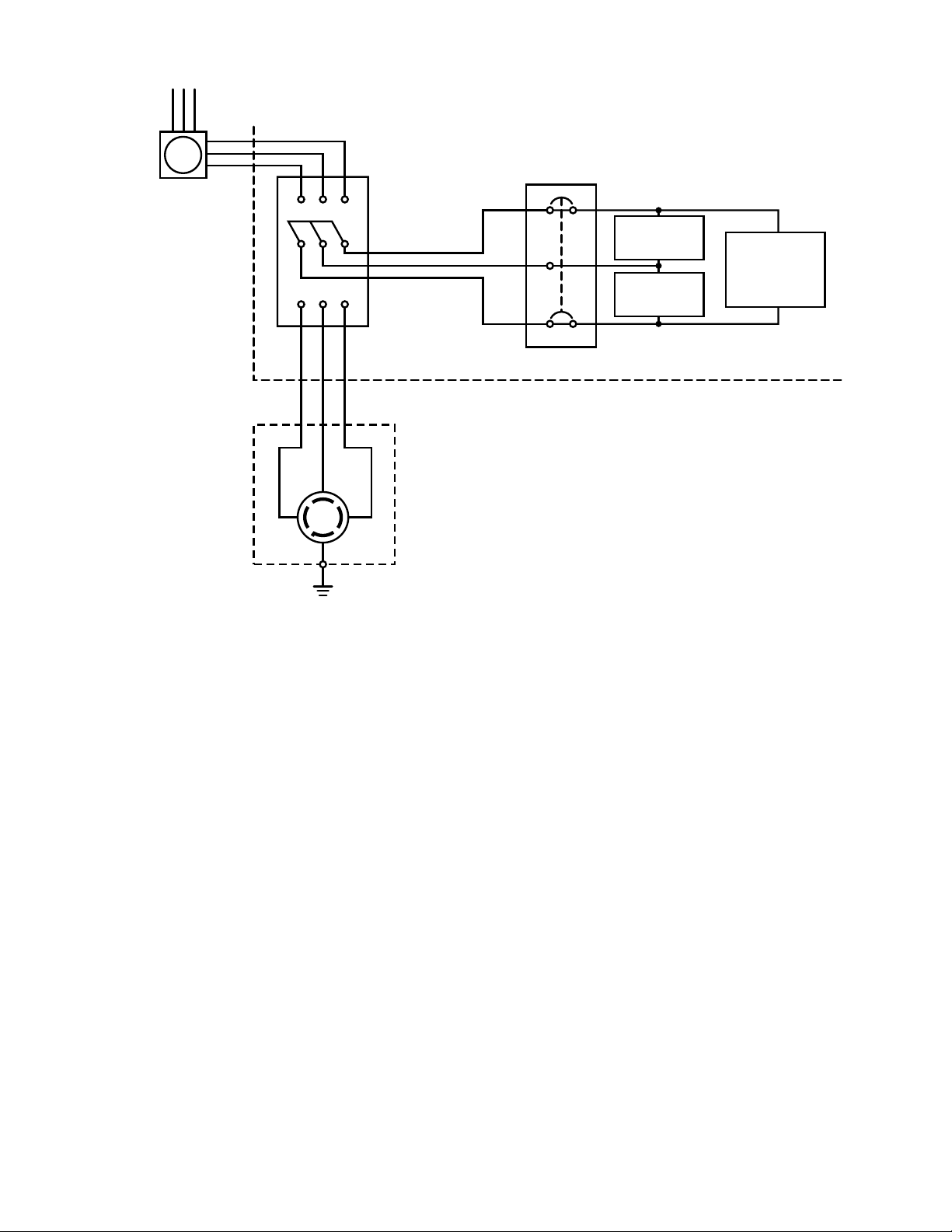
Utility high line
Meter box
Generator
XWY
X
WY
Transfer
switch
(W)
(X)(
)
Y
(G)
240V
4P- Receptacle
House circuit breaker
120V
appliance
120V
appliance
240V
appliance
Fig. 5-10
(c) Operating the generator.
Set the full power switch to 120V/ 240V side.
Turn the house AC breaker off before starting the generator.
Start the generator and warm it up.
Turn the house AC breaker on.
Caution : Do not start the generator with electrical appliance (s) connected and with their switches on.
Otherwise the appliance (s) may be damaged by the surge voltage at starting.
-
15
-
Page 19
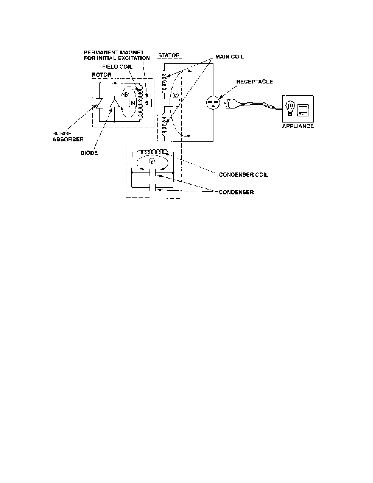
5-3 GENERATOR OPERATION
Fig. 5-11
5-3-1 GENERATION of NO-LOAD VOLTAGE
(1) When the generator starts running, the permanent magnet built-in to the rotor generates 3 to 6V of AC
voltage in the main coil and condenser coil wound on the stator.
(2) As one or two condensers are connected to the condenser coil, the small voltage at the condenser
coil generates a minute current a which flows through the condenser coil. At this time, a small flux is
produced with which the magnetic force at the rotor’s magnetic pole is intensified. When this magnetic force is intensified, the respective voltages in the main coil and condenser coil rise up. As the
current a increases, the magnetic flux at the rotor’s magnetic pole increases further. Thus the voltages at the main coil and condenser coil keep rising by repeating this process.
(3) As AC current flows through the condenser coil, the density of magnetic flux in the rotor changes. This
change of magnetic flux induces AC voltage in the field coil, and the diode rectifier in the field coil
circuit rectifies this AC voltage into DC. Thus a DC current b flows through the field coil and magne-
tizes the rotor core to generate an output voltage in the main coil.
(4) When generator speed reaches 3000 to 3300 rpm, the current in the condenser coil and field coil
increases rapidly. This acts to stabilize the output voltage of each coils. If generator speed further
increases to the rated value, the generator output voltage will reach to the rated value.
5-3-2 VOLTAGE FLUCTUATIONS UNDER LOAD
When the output current c flows through the main coil to the appliance, a magnetic flux is produced and
serves to increase current a in the condenser coil. When current a increases, the density of magnetic
flux across the rotor core rises. As a result, the current flowing in the field coil increases and the generator output voltage is prevented from decreasing.
-
16
-
Page 20
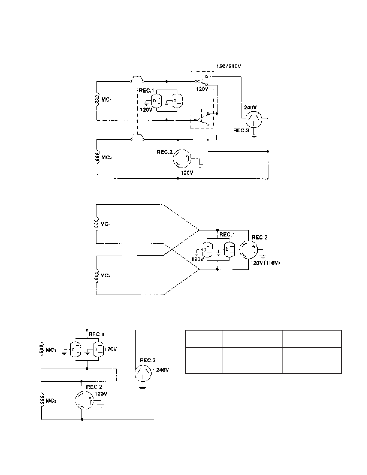
5-3-3 FULL POWER SWITCH (Dual Voltage Type)
The full power switch is provided for the dual voltage type to take out the full rated power from one
receptacle in each voltage.
Fig. 5-12
Fig. 5-14
Fig. 5-13
-
17
-
hctiwS
noitisoP
V042/021tuptuodetarfoflaHtuptuodetaR
Table. 5-3
EGATLOVREWOL
ELCATPECER
EGATLOVREHGIH
ELCATPECER
Page 21

Two main coils are wound over stator core. Each main coil outputs half the rated power at the lower
voltage (120V). These main coils are wound to be in the same phase. The full power switch reconnects
these main coils in parallel or in series.
Fig. 5-12 shows a circuit diagram. When the full power switch is set for single lower voltage indication
(120V), the switch position is as indicated by the lower solid line in the diagram. Fig. 5-13 is a simplified
representation of this circuit, showing the two main coils connected in parallel. In this case, the higher
voltage (240V) at Rec. 3 cannot be taken out. Rec. 2 for the lower voltage can output up to the rated
power (up to 30A if the rated current is over 30A), and Rec. 1 can output up to a total of 15A.
When the full power switch is set for double voltage indication (120V/240V), the switch position is as
indicated by the upper dotted line in Fig. 5-12. Fig. 5-14 is a simplified representation of this circuit,
showing the two main coils connected in series. In this case, power can be taken simultaneously from
the receptacles for the both voltages. Rec. 3 for the higher voltage can output up to the rated power, but
Rec. 1 and Rec. 2 for the lower voltage can output only up to half the rated power each.
Table 5-4 is a summary of the above explanation. Select the proper output voltage by full power switch in
accordance with the appliance to be used.
-
18
-
Page 22
5-4 OIL SENSOR
OIL SENSOR
5-4-1 DESCRIPTION
* The oil sensor mainly functions to detect posi-
tion of the surface of engine oil in the crankcase
of engines for general use and to stop the engine automatically when the oil level goes down
below the lower limit specified. This prevents seizure of engine from occurring due to insufficient
amount of oil in the crankcase.
* Since the sensor has been designed to consume
a part of power supplied to the igniter to energize its electronics circuit, any other external
power supply is not necessary so that it can be
mounted at the oil filler port.
Introduction of newly developed sensing principle features super durability and no change with the
passage of time as it does not use any moving part.
Merits due to introduction of electrical conductivity detection are as follows ;
Fig. 5-15
1 It has resistance to mechanical shocks and property of no change with the passage of time as
sensing element consists simply of electrodes having no moving parts.
2 At the same time, it is capable of detecting the oil level stably as it is not influenced by engine
vibrations.
3 No error occurs due to foam and flow of the oil.
4 Influence against the ignition system or the electronics units can be neglected because an electric
current supplied to the sensor can be decreased.
5-4-2 PRINCIPLE OF SENSING OIL LEVEL
There is a great difference between electric resistance of air and that of oil. Since the resistance of air is
far higher than that of oil, more electric current passes through the oil than through the air, although
absolute value of the current is very small. The sensor detects this current difference and make use of it.
The sensor judges the oil quantity , by comparing a current flowing across a pair of electrodes (inner and
outer) with the reference, in such a way that if a current flows between the electrodes more than the
reference, sufficient oil is in the crankcase, on the other hand, if a current flows less than the reference,
oil is not sufficient. Since an electric current is flown to detect oil quantity, this is called the “electrical
conductivity detection” type of sensor. The oil level to be detected is determined by the length of electrodes and their mounting positions with the engine.
5-4-3 HOW IT OPERATES
[Power supply]
The sensor makes use of a part of primary power source for ignition of the engine (igniter) to drive the
sensor circuit. Power to the sensor can usually be derived from the “stop button” by branching wires out.
-
19
-
Page 23
[Judgement of oil level]
When sufficient oil is in the crankcase, both of inner and outer electrodes are immersed in the oil through
which current flows across the electrodes. The sensor judges that oil in the crankcase is sufficient. When
oil level goes down and the inner electrode is exposed to the air due to consumption of oil, no current flow
between the electrodes as air is considered to be electrically nonconductive. The sensor in this case
judges that oil is insufficient.
[Decision of oil shortage]
Oil level at the electrodes may go down momentarily probably due to the engine being slanted or affected
by vibration even if a sufficient oil is in the crankcase. For that reason, the sensor has an electronic timer
circuit to prevent it from interpreting as short of oil when amount of oil is sufficient. The sensor has been
designed so that the engine is to be stopped only when oil-shortage is detected for 5 seconds uninterrupted. The timer employs an integration circuit and it is to be reset when the inner electrode is soaked in
the oil again before the sensor decides it as oil-shortage. The oil level where the sensor decides as oilshortage, when oil level goes down gradually, is called “threshold level”.
[Automatic stop of engine]
When the sensor decides as oil-shortage, it makes the engine to stop running automatically for protection of engine. Once the stopping circuit is activated, it keeps functioning until it confirms that the engine
has made a complete stop, then the circuit stops functioning automatically.
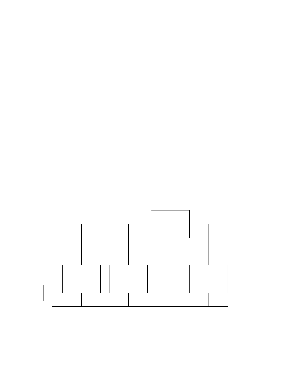
5-4-4 BLOCK DIAGRAM OF THE CIRCUIT
Power circuit
Detection
Inner pole
Oil
Outer pole Engine ground
Detection
circuit
circuit
Deley circuit
Fig. 5- 16
Stopping
circuit
Igniter
1 Power circuit..........This rectifies a part of power to the igniter and regulates it to supply the stabi-
lized power to necessary circuits.
-
20
-
Page 24

2 Detection circuit ..... This detects quantity of oil, sufficient or not, according to difference of electric
resistance across inner and outer electrodes.
3 Delay circuit ........... This his prevents the sensor from making an unnecessary stop of the engine
by momentary lowering of the oil level due to the engine being slanted or
affected by vibration in spite of sufficient oil in the crankcase.
4 Stopping circuit...... This automatically stops the engine running.
5-4-5 CAUTIONS TO BE TAKEN ON HANDLING THE SENSOR
(1) Oil sensor unit
1 Be sure not to damage each wire. Broken or short-circuited power supply wires and/or a ground-
ing wire in particular may lead to malfunction or breakdown.
2 The sensor is not interchangeable from engine to engine because the sensor is to be exclusively
installed individually in each engine employed.
(2) Mounting and wiring of oil sensor unit
1 Although this has been designed to have enough antinoise properties in practical use, do not
route the sensor wirings in the vicinity of noise-generating sources such as ignition plugs or high
voltage cords. This may cause malfunction or breakdown.
2 Since capacity of power source is limited, current flown in the electronic circuit of the sensor is
kept as low as possible. Be sure to use terminals with a high contact reliability of more than that of
tinned terminals.
(3) Operation of oil sensor
1 If operating with the engine kept tilted, oil surface inside of the engine varies and the correct oil
level can not to be detected which in turn obstructs the preventing function of engine seizure.
Operate the engine by keeping it level.
2 When starting the engine with an insufficient oil in the crankcase, engine starts once then it stops
automatically after it runs for 5 seconds.
3 When the engine has been stopped by the oil sensor, voltage remained in the electronic circuit
prevents the sensor from being restarted for 3 seconds after the engine stop. Try to restart the
engine after 3 seconds or more.
-
21
-
Page 25
6. SAFETY PRECAUTIONS
1. Use extreme caution near fuel. A constant danger of explosion or fire exists.
Do not fill the fuel tank while the engine is running. Do not smoke or use open flame near the fuel tank.
Be careful not to spill fuel when refueling. If spilt, wipe it and let dry before starting the engine.
2. Do not place inflammable materials near the generator.
Be careful not to put fuel, matches, gunpowder, oily cloth, straw, and any other inflammables near the
generator.
3. Do not operate the generator in a room, cave or tunnel. Always operate in a well-ventilated
area.
Otherwise the engine may overheat and also, the poisonous carbon monoxide contained in the exhaust gases will endanger human lives. Keep the generator at least 1 m (4 feet) away from structures
or facilities during use.
4. Operate the generator on a level surface.
If the generator is tilted or moved during use, there is a danger of fuel spillage and a chance that the
generator may tip over.
5. Do not operate with wet hands or in the rain.
Severe electric shock may occur. If the generator is wet by rain or snow, wipe it and thoroughly dry it
before starting. Don’ t pour water over the generator directly nor wash it with water. If the generator is
wet with water, the insulations will be adversely affected and may cause current leakage and electric
shock.
6. Do not connect the generator to the commercial power lines.
This may cause a short-circuit or damage to the generator. Use a transfer switch (Optional parts) for
connecting with indoor wiring.
NOTE : The parts numbers of the transfer switches and of the plastic box to store them are as shown in
Table 6-1.
.oNtraPemaNtraPyt'QesahPtnerruCelbawollA
80-40654-563hctiwSrefsnarT11A51
80-50654-763hctiwSrefsnarT11A03
80-60654-043hctiwSrefsnarT11A06
80-80034-763xoBcitsalP11A03
80-90034-843xoBcitsalP11A06
Table. 6-1
7. Be sure to check and remedy the cause of circuit breaker tripping before resetting it on.
CAUTION : If the circuit breaker tripped off as a result of using an electrical appliance, the cause
can be an overload or a short-circuit. In such a case, stop operation immediately and carefully
check the electrical appliance and AC plugs for faulty wiring.
-
22
-
Page 26

7. RANGE OF APPLICATIONS
Generally , the power rating of an electrical appliance indicates the amount of work that can be done by it.
The electric power required for operating an electrical appliance is not always equal to the output wattage of the appliance. The electrical appliances generally have a label showing their rated voltage, frequency, and power consumption (input wattage). The power consumption of an electrical appliance is
the power necessary for using it. When using a generator for operating an electrical appliance, the power
factor and starting wattage must be taken into consideration.
In order to determine the right size generator, it is necessary to add the total wattage of all appliances to
be connected to the unit.
Refer to the followings to calculate the power consumption of each appliance or equipment by its type.
(1) Incandescent lamp, heater, etc. with a power factor of 1.0
Total power consumption must be equal to or less than the rated output of the generator.
Example : A rated 3000W generator can turn thirty 100W incandescent lamps on.
(2) Fluorescent lamps, motor driven tools, light electrical appliances, etc. with a smaller power
factor
Select a generator with a rated output equivalent to 1.2 to 2 times of the power consumption of the
load. Generally the starting wattage of motor driven tools and light electrical appliances are 1.2 to 3
times lager than their running wattage.
Example : A rated 250 W electric drill requires a 400 W generator to start it.
NOTE1 : If a power factor correction capacitor is not applied to the fluorescent lamp, the more power
shall be required to drive the lamps.
NOTE2 : Nominal wattage of the fluorscent lamp generally indicates the output wattage of the lamp.
Therefore, if the fluorescent lamp has no special indication as to the power consumption, efficiency should be taken into account as explained in ltem (5) on the following page.
(3) Mercury lamps with a smaller power factor
Loads for mercury lamps require 2 to 3 times the indicated wattage during start-up.
Example : A 400 W mercury lamp requires 800 W to 1200 W power source to be turned on. A rated
3000 W generator can power two or three 400 W mercury lamps.
(4) Initially loaded motor driven appliances such as water pumps, compressors, etc.
These appliances require large starting wattage which is 3 to 5 times of running wattage.
Example : A rated 900 W compressor requires a 4500 W generator to drive it.
NOTE1 : Motor-driven appliances require the aforementioned generator output only at the starting. Once
their motors are started, the appliances consume about 1.2 to 2 times their rated power consumption so that the excess power generated by the generator can be used for other electrical
appliances.
NOTE2 : Motor-driven appliances mentioned in items (3) and (4) vary in their required motor starting
power depending on the kind of motor and start-up load. If it is difficult to determine the optimum
generator capacity, select a generator with a larger capacity.
-
23
-
Page 27

(5) Appliances without any indication as to power consumption
Some appliances have no indication as to power consumption; but instead the work load (output) is
indicated. In such a case, power consumption is to be worked out according to the numerical formula
mentioned below.
(Output of electrical appliance)
= (Power consumpition)
(Efficiency)
Efficiencies of some electrical appliances are as follows :
Single-phase motor................................ 0.6 to 0.75
Fluorescent lamp ................................... 0.7 to 0.8
The smaller the motor, the
()
lower the efficiency.
Example 1: A 40W fluorescent lamp means that its luminous output is 40W. Its efficiency is 0.7 and
accordingly, power consumption will be 40÷ 0.7= 57W. As explained in Item (2), multiply
this power consumption value of 57 W by 1.2 to 2 and you will get the figure of the necessary capacity of a generator. In other words, a generator with a rated output of 1000W
capacity can light nine to fourteen 40 W fluorescent lamps.
Example 2 : Generally speaking, a 400 W motor means that its work load is 400 W. Efficiency of this
motor is 0.7 and power consumption will be 400÷0.7= 570 W. When this motor is used for
a motor-driven tool, the capacity of the generator should be multiple of 570 W by 1.2 to 3 as
explained in the ltem (3). 570 (W) x 1.2 to 3 = 684 (W) to 1710 (W)
LEDOM0082VGR0014VGR0016VGR
ycneuqerFH06
,pmaltnesednacnI
.cte,retaeh
-rotoM,pmaltnecseroulF
esoprop-lareneg,lootnevird
.cte,pmalyrucreM
.cte,rosserpmoc,pmuP
W0032W0063W0084
.xorppa
W0021
.xorppa
W008
.xorppa
W055
Table. 7-1
.xorppa
W0081
.xorppa
W0041
.xorppa
W058
.xorppa
W0042
.xorppa
W0061
.xorppa
W0011
-
24
-
Page 28

NOTES : Wiring between generator and electrical appliances
1. Allowable current of cable
Use a cable with an allowable current that is higher than the rated input current of the load (electrical
appliance). If the input current is higher than the allowable current of the cable used, the cable will
become excessively heated and deteriorate the insulation, possibly burning it out. Table 7-2 shows
cables and their allowable currents for your reference.
2. Cable length
If a long cable is used, a voltage drop occurs due to the increased resistance in the conductors de-
creasing the input voltage to the load (electrical product). As a result, the load can be damaged. Table
7-2 shows voltage drops per 100 meters of cable.
lanoitceS
3
mm/aera
57.07 81.0/03774.2V5.2V8V5.21
52.12181.0/05684.1V5.1V5V5.7V21V51V81
0.27162.0/73259.0V0.1V3V0.5V8V01V21V51
5.33223.0/54715.0V5.1V5.2V4V5V5.6V5.7
5.55323.0/07233.0V1V2V5.2V5.3V4V5
aG
elbawollA
eriw
A/tnerruc
Voltage drop indicates as V= x R x I x L
/.oNegu
tnemele
mm/.oN
ecnatsiseR
m001/mhO
Table. 7-2
A1A3A5A8A01A21A51
m001reppordegatloV
1
100
R means resistance (Ω / 100 m) on the above table.
I means electric current through the wire (A).
L means the length of the wire (m).
The length of wire indicates round length, it means twice the length from generator to electrical tools.
-
25
-
Page 29

8. MEASURING PROCEDURES
8-1 MEASURING INSTRUMENTS
8-1-1 “Dr. ROBIN” GENERATOR TESTER
The “Dr. Robin” generator tester is exclusively
designed for fast, easy diagnosis and repair of
Robin generators. The “Dr . Robin” has the following features :
(1) Functions of voltmeter, frequency meter,
megger tester, capacitance meter and circuit
tester are combined in one unit.
(2) Fast and easy readout by digital indicator.
(3) Built-in automatic battery checker indicates the
time to change batteries.
(4) Tester and accessories are installed in a handy,
sturdy case for easy carrying.
* SPECIFICATIONS
LEDOMniboR.rD
rebmuNtraP80-56574-883
egatloVCAV005ot0
ycneuqerFzH07ot52
gnirusaeM
egnaR
rotcetorPtiucriCesuF
ecruoSrewoP yrettaBlleCyrD)P600(P44F6x2
seirosseccA
ecnatsiseR999.1ot1.0 Ω
Fig. 8-1
yticapaCresnednoC001ot01 μF
ecnatsiseRnoitalusnIM3 Ω
tes1...seborpeldeenhtiwsdaeltseT
tes1...sgulpkcajhtiwsdaeltseT
)HxWxL(snoisnemiD mm011xmm002xmm582
thgieWgk6.1
Table. 8-1
The “Dr. Robin” generator tester can be ordered from Robin generator distributors by the following part
number.
Dr. Robin Part Number : 388-47565-08
If you do not have a “Dr. Robin” generator tester, use the instruments described in the following section
for checking generator parts.
-
26
-
Page 30

8-1-2 INSTRUMENTS
(1) VOLTMETER
AC voltmeter is necessary. The approximate
AC voltage ranges of the voltmeters to be used
for various types of generators are as follows:
0 to 150V : T ype with an output voltage of 110
or 120V
0 to 300V : T ype with an output voltage of 220,
230 or 240V
0 to 150V, 0 to 330V : Dual voltage type
(2) AMMETER
AC ammeter is necessary. An AC ammeter
with a range that can be changed according
to the current rating of a given generator is
most desirable. (About 10A, 20A, 100A)
Fig. 8-2
(3) FREQUENCY METER
Frequency range : About 45 to 65Hz
NOTE : Be careful of the frequency meter’s input
voltage range.
Fig. 8-3
Fig. 8-4
-
27
-
Page 31

(4) CIRCUIT TESTER
Used for measuring resistance, etc.
(5) MEGGER TESTER
Used for measuring generator insulation re-
sistance. Select one with testing voltage range
of 500V.
Fig. 8-5
(6) T ACHOMETER
Use the contactless type tacho meter.
Fig. 8-6
Fig. 8-7
-
28
-
Page 32

8-2 AC OUTPUT MEASURING
Fig. 8- 8
Use a circuit like the shown in Fig.8-8 for measuring AC output. A hot plate or lamp with a power factor of
1.0 may be used as a load. Adjust the load and rpm. and check that the voltage range is as specified in
Table 8-2 at the rated amperage and rated rpm.
egatlovdetaRV021V042
egnaregatloVV231-801V462-612
Table. 8-2
8-3 DC OUTPUT MEASURING
Fig. 8- 9
Measurement of DC output is executed with the switch turned ON while the current is regulated at 8.3A
by adjusting the load to the generator. If the voltage is within the range from 6V to 14V, the voltage output
is normal.
NOTE : If a battery is connected as a load to the generator, the DC output voltage will increase by
approximately 1 to 2 V . Therefore, carefully observe the electrolyte level and do not overcharge
the battery.
-
29
-
Page 33

8-4 MEASURING INSULATION RESISTANCE
Use a “Dr. Robin” generator tester in megger tester
mode or use a megger tester to check the insulation resistance. Connect a megger tester to one
of receptacle output terminals and the ground terminal, then measure the insulation resistance. An
insulation resistance of 1 megohm or more is normal. (The original insulation resistance at the time
of shipment from the factory is 10 megohm or
more.) If it is less than 1 megohm, disassemble
the generator and measure the insulation resistance of the stator, rotor and control panel individually.
NOTE : Turn on the no-fuse breaker before mea-
surement.
* STATOR
Fig. 8-10
(1) Measure the insulation resistance between
BLUE lead and the core.
(2) Measure the insulation resistance between
WHITE lead and the core.
(3) Measure the insulation resistance between
YELLOW lead and the core.
(4) Measure the insulation resistance between
BROWN lead and the core.
* ROTOR
Measure the insulation across one of the soldered
terminals of the rotor and the core.
Fig. 8-11
Fig. 8-12
-
30
-
Page 34

* CONTROL PANEL
Measure the insulation resistances between the
live parts and the grounded parts.
Fig. 8-13
Any part where the insulation resistance is less than 1MΩ has faulty insulation, and may cause electric
leakage and electric shock.
Replace the faulty part.
-
31
-
Page 35

9. CHECKING FUNCTIONAL MEMBERS
9-1 VOLTMETER
Check the voltmeter if it is turned on by applying
specific voltage. Voltmeter cannot be checked with
circuit tester because its resistance is too large.
1 Check that no disconnection nor short-circuit
occurs with a tester, and the internal resistance
is around 00k ohms normally.
2 Turn on the commercial power supply input
and check the indication.
9-2 AC RECEPTACLES
Fig. 9-1
Using a “Dr. Robin” or a circuit tester, check continuity between the two terminals at the rear of the AC
receptacles while the receptacle is mounted on the control panel. When continuity is found between the
output terminals of the receptacle with a wire connected across these terminals, the AC receptacle is
normal. When the wire is removed and no continuity is found between these terminals, the receptacles
are also normal.
WIRE
AC RECEPTACLE
Fig. 9-2A
Fig. 9-2B
9-3 No-FUSE BREAKER
Check continuity between each of two terminals
at the rear of the no-fuse breaker while it is
mounted on the control panel. Normally, there is
continuity between each of the two when the nofuse breaker is on while there is no continuity when
the no-fuse breaker is off.
NO-FUSE BREAKER
Fig. 9-3
-
32
-
Page 36

9-4 STATOR
Disengage connectors on the wires from stator
and check the resistance between wires with a
“Dr. Robin” or a circuit tester referring to the following table.
Fig. 9-4
noitacificepSgnidniWCA
LEDOM
zHegatloVdeR/etihWeulB/kcalBwolleY/wolleY
0082VGR 06V042/V021,V02185.085.076.1
0014VGR 06V042/V021,V02125.025.099.0
0016VGR 06V042/V021,V02152.052.085.0
Table. 9-1
resnednoC
gnidniW
NOTE : If the circuit tester is not sufficiently accurate, it may not show the values given and may give
erroneous readings. Erroneous readings will also occur when there is a wide variation of resistance among coil windings or when measurement is performed at ambient temperatures different from 20
°
C (68 °F).
-
33
-
Page 37

9-5 ROTOR ASSEMBLY
(1) Using a “Dr. Robin” or a circuit tester, measure the resistance of the field coil at the terminals.
(Ω )
LEDOM0082VGR0014VGR0016VGR
ECNATSISER 57.1 Ω 77.1 Ω 06.1 Ω
Table. 9-2
NOTE 1 :
Because a diode is soldered to the coil ends at
the terminals, resistance may be measured only
when tester probes touche the terminals in one
combination of polarity . Therefore, if no resistance
reading appears, try checking in reverse polarity .
NOTE 2 :
If the circuit tester is not sufficiently accurate, it
may not show the values given and may give erroneous readings. Erroneous reading will also
occur when there is a wide variation of resistance
among coil windings or when measurement is
performed at ambient temperatures different from
20
°
C (68 °F).
Fig. 9-5
9-6 CONDENSER
Use a “Dr. Robin” in capacitance meter mode to check the capacity of condensers.
Fig. 9-6B Type RGV4100, RGV6100Fig. 9-6A Type RGV2800
NOTE : Be sure to discharge condensers by shorting condenser leads each other before checking their
capacitance, or the accurate reading cannot be obtained.
-
34
-
Page 38

RESNEDNOCFOYTICAPACLAMRON
0082VGR0014VGR0016VGR
42 μF02 μ 2xF82 μ 2xF
Table. 9- 3
* If such an instrument is unavailable, the condenser can be checked by replacing with a new one. If the
generator performs good with new condenser, the cause of trouble is defect in original condenser.
9-7 DIODE RECTIFIER
Fig. 9- 7 Fig. 9- 8
Circuit inside of the diode rectifiers is as shown in Fig. 9-7. Check continuity between each terminal by
using a circuit tester as shown in Fig. 9-8. The rectifier is normal when condtinuity is as follows:
* Checking table for analogue circuit tester.
retsettiucricehtfoeldeen)sunim(kcalbylppA
retsettiucriceugolanA
nworBnworBegnarO
nworB ---------ytiunitnocoNytiunitnocoNytiunitnoC
foeldeen)sulp(derylppA
retsettiucriceht
nworB ytiunitnocoN---------ytiunitnocoNytiunitnoC
egnarO ytiunitnoCytiunitnoC---------ytiunitnoC
etihW/nworB ytiunitnocoNytiunitnocoNytiunitnocoN---------
Table. 9-4 -1
etihW/nworB
-
35
-
Page 39

* Checking table for digital circuit tester.
retsettiucriclatigiD
nworB ---------ytiunitnocoNytiunitnocoNytiunitnoC
nworBnworBegnarO
retsettiucricehtfoeldeen)sulp(derylppA
etihW/nworB
eldeen)sunim(kcalbylppA
retsettiucricehtfo
nworB ytiunitnocoN---------ytiunitnocoNytiunitnoC
egnarO ytiunitnoCytiunitnoC---------ytiunitnoC
etihW/nworB ytiunitnocoNytiunitnocoNytiunitnocoN---------
Table. 9-4-2
NOTE 1 : Because of the difference of measuring method between the analogue circuit tester and the
digital circuit tester, polarity of tester needles should be reversed.
NOTE 2 : ”Continuity” means forward direction characteristics of the diode, and different from short
circuit condition (in which a pointer of the tester goes out of its normal scale), shows resistance
to some extent. When results of the checking indicates failure even in one section, replace
with a new one.
NOTE 3 : Simpson brand analogue testers have the characteristics as same as the digital circuit tester.
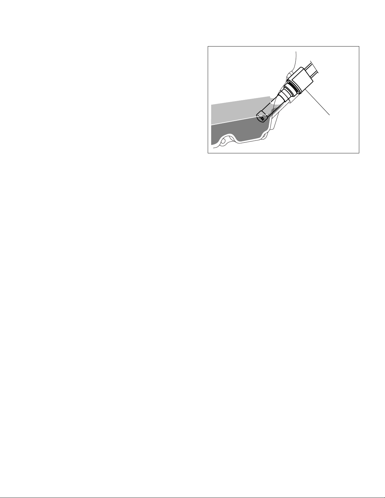
9-8 OIL SENSOR
(1) Disconnect two (2) wires comming from the
sensor at the connection.
(2) Loosen the sensor to remove it from the en-
gine.
(3) Plug the opening of oil filler hole (created after
sensor is removed) with suitable means such
as oil gauge.
(4) Connect the removed wires again with the oil
sensor.
(5) Start the engine with the oil sensor removed
Fig. 9-9
and confirm if ;
a. Engine stops after 5 seconds which is normal, or
b. Engine does not stop after more than 10 seconds which is unusual.
NOTE : The sensor will not operate properly when wire is broken or poorly connected. Check the wires
for correct connection. If it fails to stop within 5 seconds after the wirings have checked, the
sensor is wrong. Replace the sensor with new one.
-
36
-
Page 40

10. DISASSEMBLY AND ASSEMBLY
10-1 PREPARATION and PRECAUTIONS
1) Be sure to memorize the location of individual parts when disassembling the generator so that the
generator can be reassembled correctly . Tag the disassembled part with the necessary information to
facilitate easier and smoother reassembly.
2) For more convenience, divide the parts into several groups and store them in boxes.
3) To prevent bolts and nuts from being misplaced or installed incorrectly, replace them temporarily to
their original position.
4) Handle disassembled parts with care; clean them before reassembly using a neutral cleaning fluid.
5) Use all disassembly/assembly tools properly, and use the proper tool for each specific job.
-
37
-
Page 41

10-2 DISASSEMBLY PROCEDURES
petSevomerottraPnoitpircseDskrameRlooT
1xoblortnoCfomottobehtmorfgnihsubehtffoekaT)1(
).1-01.giFeeS(.xoblortnoceht
gniriwehtnosrotcennocehttcennocsiD)2(
.rotanretlaehtotxoblortnocehtmorf
).1-01.giFeeS(
ehtdnaxoblortnocehtmorfneewteb
).2-01.giFeeS(.enigne
Fig. 10-1 Fig. 10-2
.tuo
gniriwehtnosrotcennocehttcennocsiD)3(
fodnereppuehtsserP
llupdnagnihsubeht
dnatlobmm21x5
dnatlobmm52x5
Fig. 10-3
ehtevomerdnastlobruofehtffoekaT)4(
).3-01.giFeeS(.emarfehtxoblortnoc
.scp2...)kcalb(y'ssArehsaw
.scp2...)kcalb(y'ssArehsaw
-
38
-
rennapSmm8
Page 42

petSevomerottraPnoitpircseDskrameRlooT
2knaTleuF.kantehtmorfleufegrahcsiD)1(
tuobaeractsomtuesU
.reniartsleufehttuhS.1
.drazaherif
.pucreniartsehtevomeR.2
ehtrednuleufeviecerotlessevatuP.3
otkcocleufehtnepodnareniarts
leuftilpsffoepiW
.ylhguoroht
).4-01.giFeeS(.leufegrahcsid
reniartsehtotpucreniartsehthcattA.4
.ydob
.neercs
retlifehtesoltonoD
RUBBER PIPE
HOSE CLAMP
)2(.reniartsehtmorfepiprebburtcennocsiD
Fig. 10-4
sreilP
ehtfopotehtnopmalcesohehtnesooL
morfepiprebburehttuollupdnareniarts
.reniartseht
leuf(rebburdnastlobruofehtffoekaT)3(
.knatleufehtevomernehtdna)knat
hcnerwxob
rorennapsmm01
).6-01.giFeeS(
Fig. 10-5
Fig. 10-6
-
39
-
Page 43

petSevomerottraPnoitpircseDskrameRlooT
3dnarelffuM
ehtxifhcihwstlobowtehtevomeR)1(
revocrelffuM
.enigneehtmorfrelffumeht
.scp2...tunsselniatsmm8
.scp2...rehsawgnirpsmm8
0016VGRdna0014VGRrof
.ecp1...teksagrelffuM
).8-01.giFeeS(
.revocraer
owtehtnesooL.rotanretlaehtotrelffum
evomerdnaegnalfrelffumehtnostun
.scp2...y'ssArehsawdnatlobmm02x8
ehtdna1revocrelffumehtevomeR)2(
.relffumehtmorf2revocrelffum
.scp8...y'ssArehsawdnatlobmm01x6
ehtmorftekcarbrelffumehtevomeR)3(
.scp2...y'ssArehsawdnatlobmm02x8
hcnerwxob
hcnerwxob
hcnerwxob
rorennapsmm21
rorennapsmm01
rorennapsmm21
Fig. 10-7Fig. 10-8
-
40
-
Page 44

petSevomerottraPnoitpircseDskrameRlooT
4emarFepiP0016VGRroF)1(
.emarf
MOUNT
RUBBER
(ALTERNATOR
SIDE : 2 pcs)
rennapsmm01
.emarfehtmorfreniartsleufehtevomeR
enignegnixiferahcihwstunehtevomeR)2(
rennapsmm21
.srebburtnuomehtotrotanretladna
).9-01.giFeeS(
enigneehtpugnils,kcolb-niahcagnisU)3(
ehtmorftnuomsiddnarotanretladna
riaehtevomeR
rofrevocrenaelc
.gnitnuomsid
FUEL STRAINER
Fig. 10-9
(
For RGV6100
MOUNT RUBBER
(ENGINE SIDE : 2 pcs)
)
.scp4...tunegnalf8M
SPACER : 1 pce.
MOUNT RUBBER : 2 pcs.
FRAME
M5 SCREW : 1 pce.
EARTH
CORD
M8 FLANGE
NUT : 2 pcs.
ehtmorfsrebburtnuomehtevomeR)4(
mottobehtnostunehtnesooL.emarf
).01-01.giFeeS(.emarfehtfoedis
Fig. 10-10
rorennapsmm21
hcnerwtekcos
STOPPER PLATE
MOUNT RUBBER : 2 pcs.
M8 FLANGE
NUT : 2 pcs.
-
41
-
Page 45

petSevomerottraPnoitpircseDskrameRlooT
5revocraeR).11-01.giFeeS(.revocdneehtevomeR)1(
Fig. 10-11 Fig. 10-12
6φ .scp3...tlob
6φ .scp4...tlob
rorennapsmm01
)0016VGRtpecxE(
ehtnetsafhcihwstlobruofehtevomeR)2(
.giFeeS(.revoctnorfehtotrevocraer
).21-01
hcnerwxob
rorennapsmm01
hcnerwxob
ehtnognittihybrevocraerehtevomeR)3(
remmahcitsalpahtiwrevocraerfosgel
.nesoolot
REAR COVER
Fig. 10-13
tihgnortsaevigtonoD
.sgelrossobehtno
remmahcitsalP
-
42
-
Page 46

petSevomerottraPnoitpircseDskrameRlooT
6rotatS.revocrotatsehtevomeR)1(
STATOR COVER
STATOR
Fig. 10-14
REAR COVER
SPRING
WASHER : 4 pcs.
COVER BOLT : 4 pcs.
STATOR COVER
STATOR
BRUSHING
GROMMET
Fig. 10-15
-
43
-
Page 47

petSevomerottraPnoitpircseDskrameRlooT
7rotoR.tlobhguorhtehtffoekaT)1(
Fig. 10-16
.nwodedisretratsliocer
hcnerwxoB
fodaehehtnohcnerwxobaylppA
remmahcitsalP
htiweldnahhcnerwehttiH.tlobhguorht
.nesoolotesiwkcolc-retnuocremmaha
elbatgnikrowehtnoenigneehttuP)2(
tuognilluproflootasaliodnatlobaesU)3(
:serudecorpgniwollofehtnirotor
foelohretnecehtotnilioenigneruoP.1
.dnetfahsehtotliohtiwlliF.tfahsrotor
).71-01.giFeeS(
daerhtgniwollofehthtiwtlobaeraperP.2
:ezis
5.1Px01M...0082VGR
5.1Px21M...0016,0014VGR
ehtdnuoraepatlaesfosnrutwefaylppA.3
).81-01.giFeeS(.tlobehtfopit
SEAL TAPE
Fig. 10-17
Fig. 10-18
-
44
-
Page 48

petSevomerottraPnoitpircseDskrameRlooT
7rotoRrotorehtfodaerhtehtotnitlobehtwercS.4
ruoytuokcitstonoD
.tfahs
hcnerwtekcosagnisutlobehteuqroT.5
.esoolffosemocrotorehtlitnu
ehtedisnierusserpciluardyhehT*
morfrotorehttrapasekattfahsrotor
.tfahsenigneeht
tfahsrotormorfylhguorohtlioffoepiW)4(
.tfahsOTPenignedna
.noitarapes
.rotorehtrevoecaf
nopupmujyamtI
hcnerwtekcoS
8revoCtnorF.revoctnorfehtevomeR)1(
Fig. 10-19
tekcosmm21
ehtevomerdnastlobruofehtnesooL
.revoctnorf
.scp4...y'ssArehsawdnatlobmm02x8M
Fig. 10-20
hcnerw
-
45
-
Page 49

10-3 ASSEMBLY PROCEDURES
10-3-1 FRONT COVER
Attach the front cover to the engine main bearing
cover. Match the faucet joint and tighten the bolts.
M8 x 20 mm bolt . . . 4 pcs.
M8 spring washer . . . 4 pcs.
euqrotgninethgiT
m-N7.31-8.11
mc-gk041-021
bl-tf1.01-7.8
10-3-2 ROTOR
(1) Wipe off oil, grease and dust from the tapered
portion of engine shaft and matching tapered
hole of rotor shaft.
Fig. 10-21
(2) Mount the rotor to the engine shaft. Tighten
the through bolt. Apply a wrench on the through
bolt and hit wrench handle clockwise with a
hammer to tighten. If an impact wrench is
available, use it.
Tightening torque :
euqrotgninethgiT
m-N2.31-3.11
0082VGR
0014VGR
0016VGR
mc-gk531-511
bl-tf8.01-7.8
m-N5.42-5.22
mc-gk052-032
bl-tf5.91-6.61
Fig. 10-22
-
46
-
Page 50

10-3-3 STATOR
STATOR COVER
STATOR
(1) Put the stator in the rear cover setting the four
grooves on the side of stator with thread holes
of the rear cover.
(2) Attach the stator cover around the stator.
10-3-4 REAR COVER
(1) Put the rear cover with stator over the rotor.
Tap on the rear cover evenly with a plastic
hammer to press the rotor bearing into the rear
cover.
(2) Fix the rear cover to the adaptor with four bolts,
spring washers, and washers.
RGV6100
M6 x 160 mm bolt . . . 4 pcs.
M6 spring washer . . . 4 pcs.
Fig. 10-23
REAR COVER
M6 washer . . . 4 pcs.
euqrotgninethgiT
m-N9.5-5.4
mc-gk06-05
bl-tf3.4-6.3
RGV2800 and 4100
M6 x 110 mm bolt . . . 4 pcs.
M6 spring washer . . . 4 pcs.
euqrotgninethgiT
m-N9.5-5.4
mc-gk06-05
bl-tf3.4-6.3
(3) Attach the bushing over the lead wire drawn
out from the rear cover. Press the smaller end
of the bushing into the window of the rear
cover.
Fig. 10-24
Fig. 10-25
-
47
-
Page 51

10-3-5 END COVER (RGV4100 only)
Attach the end cover to the rear cover.
10-3-6 FRAME
Fig. 10-26
(1) Attach the mount rubbers to the frame. Insert
FRAME UPPER
the setting tongue of mount rubber into the hole
on the frame and tighten the nut from the bottom of the frame.
M8 flange nut . . . 4 pcs.
euqrotgninethgiT
m-N7.31-8.11
mc-gk041-021
bl-tf8.01-7.8
Fig. 10-27
NOTE : The mount rubbers are selected to reduce vibration most effectively by model. Be sure to use
the correct mount rubber for your generator. Although mount rubbers have the same appearance, their characteristics are different.
(2) Attach the 5 mm terminal of the grounding wires (green / yellow) to the unpainted thread hole of the
frame base plate using a 5 mm brass screw.
(3) Install the engine and alternator assembly into
euqrotgninethgiT
the frame. Put the engine and alternator assembly into the frame from the side of it.
Tighten the nuts over the mount rubber bolts
to fix.
m-N7.31-8.11
mc-gk041-021
bl-tf8.01-7.8
M8 nuts . . . 4 pcs.
NOTE : Remove the air cleaner cover for easier installation.
NOTE : When tightening the nuts, slightly lift the engine and alternator assembly so that the weight is not
applied to the mount rubbers.
-
48
-
Page 52

(4) Fasten the other earth cable with 5 mm termi-
nal to the unpainted bolt hole on the frame.
(See Fig.10-28.)
10-3-7 MUFFLER and MUFFLER COVER
(1) Temporarily fix the muffler bracket to either the
rear or front covers for RGV6100 or RGV2800.
M8 x 20 mm bolt and washer Ass’y . . . 2 pcs.
(2) Attach the muf fler cover 1 and the muffler cover
2 to the muffler.
M6 x 10 mm bolt and washer Ass’y . . . 8 pcs.
euqrotgninethgiT
m-N8.9-9.7
mc-gk001-08
bl-tf2.7-8.5
EARTH CABLE
Fig. 10-28
(3) Put the muffler gasket to the engine.
(4) Attach the muffler with muffler cover to the
engine and the rear cover .
1 Tighten the two nuts for the muffler first. Use
the spring washers for RGV4100 and
RGV6100.
8 mm stainless nut . . . 2 pcs.
8 mm spring washer . . . 2 pcs.
(for RGV4100 and RGV6100 only)
euqrotgninethgiT
m-N4.72-6.12
mc-gk082-022
bl-tf2.02-8.51
2 Tighten the bolts to fix the muffler to the rear
cover.
M8 x 20 mm bolt and washer Ass’y . . . 2 pcs.
(for RGV4100)
euqrotgninethgiT
m-N5.42-6.81
mc-gk052-091
bl-tf0.81-7.31
-
49
-
Fig. 10-29
Page 53

3 For RGV2800 and 6100 : T ighten the two bolts to fix the muf fler bracket to the front cover, rear cover,
and then the two bolts for the muffler to the muffler bracket.
M8 x 20 mm bolt and washer Ass’y . . . 4 pcs. (for RGV2800 and 6100)
euqrotgninethgiT
m-N5.42-6.81
mc-gk052-091
bl-tf0.81-7.31
10-3-8 FUEL TANK
(1) For RGV2600 and RGV4100 only :
Attach the fuel strainer to the bottom of the
fuel tank. Screw in the fuel strainer all the way
and return one to two turns, and then lock it
with the lock nut.
For RGV6000 only :
Attach the fuel strainer to the frame.
euqrotgninethgiT
m-N9.6-9.4
mc-gk07-05
bl-tf0.5-6.3
(2) Mount the fuel tank on the frame with rubber
washers between the tank flange and the frame.
M6 x 20 mm bolt (black) . . . 4 pcs.
Rubber washer . . . 4 pcs.
NOTE : For easy tank assembly, glue the rubber
washers over the mounting holes of the
frame.
(3) Connect the rubber pipe.
First, fit the hose clamps on the rubber pipe and
connect it to the strainer and the carburetor. Then
fasten it with the hose clamps.
For RGV6100, connect the rubber pipe to the
strainer and the fuel tank in the same way.
NOTE : Apply a drop of oil to the rubber pipe for
easier connection.
-
50
Fig. 10-30
-
Page 54

10-3-9 FRONT PANEL
Mount the front panel assembly to the frame.
Refer to Section 10-4 for disassembly, checking and reassembly procedures of the front panel.
(1) Connect the wires from the front panel and
the engine.
(2) Connect the wires drawn out from the stator to
the wires from the front panel.
NOTE : Connect the wires of the same color.
(3) Press the upper end of the bushing into the
bottom window of the front panel.
(4) Mount the front panel to the frame.
M5 x 12 mm bolt and washer Ass’y . . . 2 pcs.
M5 x 25 mm bolt and washer Ass’y . . . 2 pcs.
Fig. 10-31
10-4 CHECKING, DISASSEMBLY and REASSEMBL Y of the FRONT PANEL
10-4-1 CHECKING OF THE FRONT PANEL
Dismount the front panel from frame. Remove the control panel and check each components and wiring.
Refer to Section 9 for the detail of checking procedure for the components in the front panel.
10-4-2 DISASSEMBLY
(1) Remove the control panel from the front panel.
M4 screw . . . 6 pcs. (RGV2800, RGV4100)
M4 screw . . . 7 pcs. (RGV6100)
(2) Disconnect the connectors on the wires to detach the control panel and front panel.
(3) Remove the condensers and diode rectifier from the front panel.
(4) After disconnecting individual wires, remove the control panel components.
NOTE : Full power switch and pilot lamp have their wires soldered. Unsolder them to remove those parts
if necessary.
-
51
-
Page 55

10-4-3 REASSEMBLY
(1) Install the receptacles, no-fuse breaker, terminals, switches, etc. on the control panel and wire them.
NOTE : Circuit diagrams are shown in Section 12. Colored wires are used for easy identification, and are
of the correct capacity and size. Use heat-resistant type wires (permissible temperature range
75
°
C or over) in the specified gauge shown in the circuit diagrams.
(2) Install condensers, and diode rectifier into the front panel.
(3) Connect the wires of control panel components and front panel.
(4) Attach the control panel to the front panel.
M4 screw . . . 6 pcs. (RGV2800, RGV4100)
M4 screw . . . 7 pcs. (RGV6100)
euqrotgninethgiT
m-N5.1-2.1
mc-gk51-21
bl-tf9.01-7.8
-
52
-
Page 56

11. TROUBLESHOOTING
COUPLER STATOR
11-1 NO AC OUTPUT
11-1-1 CHECKING CONDENSER
(1) Check the capacity of condensers using a “Dr. Robin” generator tester in capacitance meter mode.
NOTE : Be sure to discharge condensers by shorting condenser leads each other before checking their
capacitance, or the accurate reading cannot be obtained.
(2) If such an instrument is unavailable, the condenser can be checked by replacing with a new one. If
the generator performs good with new condenser, the cause of trouble is defect in original condenser.
11-1-2 CHECKING STATOR
(1) Remove control panel and disconnect stator
wires at the connectors.
(2) Measure the resistance between terminals on
stator leads. (See Fig.1 1-2) Refer to Table 9-1
for normal resistance.
Fig. 11-1B Type RGV4100, RGV6100Fig. 11-1A Type RGV2800
RESNEDNOCFOYTICAPACLAMRON
0082VGR0014VGR0016VGR
42 μF02 μ 2xF82 μ 2xF
Table. 11-1
If stator is faulty, replace it with a new one.
Fig. 11-2
-
53
-
Page 57

(3) Check the insulation resistance between sta-
tor core and each stator lead using a Dr. Robin
generator tester in megger tester mode or a
megger tester. (Fig. 11-3)
If insulation is bad, replace stator with a new
one.
11-1-3 CHECKING ROTOR
(1) Remove rear cover and stator.
Fig. 11-3
(2) Using a Dr. Robin or a circuit tester, measure
the resistance of the field coil at the terminals.
LEDOM0082VGR0014VGR0016VGR
ECNATSISER 57.1 Ω 77.1 Ω 06.1 Ω
Table. 11-2
NOTE : Because a diode is soldered to the coil
ends at the terminals, resistance may be measured only when tester probes touch the terminals in one combination of polarity. Therefore, if
no resistance reading appears, try checking in
reverse polarity.
[Remedy]
If the resistance is not normal, replace rotor with
a new one.
Fig. 11-4
(Ω )
Fig. 11-5
-
54
-
Page 58

(3) Measure the insulation across one of the sol-
dered terminals of the rotor and the core.
(Fig.11-6)
If insulation is bad, replace rotor with a new
one.
Fig. 11-6
11-2 AC VOLTAGE IS TOO HIGH OR TOO LOW
11-2-1 CHECKING ENGINE SPEED
If the engine speed is too high or too low, adjust it
to the rated r.p.m.
[How to adjust engine r.p.m.]
* Loosen the lock nut on the adjusting screw.
* Turn the adjusting screw clockwise to decrease
engine speed or counterclockwise to increase
engine speed.
daolontadeepsenignelamroN
mpr0573ot0073
11-2-2 CHECKING CONDENSER
SPEED CONTROL LEVER
ADJUSTING SCREW
RGV2800,4100
Check condenser referring to Step 11-1-1.
11-2-3 CHECKING STATOR
Check stator referring to Step 11-1-2.
11-2-4 CHECKING ROTOR
Check rotor referring to Step 11-1-3.
RGV6100
Fig. 11-7
-
55
-
Page 59

11-3 AC VOLTAGE IS NORMAL AT NO-LOAD, BUT THE LOAD CANNOT BE APPLIED.
AIR OUTLET
(
ENGINE
)
AIR INLET
(
ALTERNATOR
)
AIR OUTLET
(
ALTERNATOR
)
AIR INLET
(
ENGINE
)
11-3-1 CHECK THE ENGINE SPEED.
If the engine speed is low, adjust it to the rated r.p.m.
*Refer to Step 11-2-1 for engine speed adjustment.
11-3-2 CHECK THE TOTAL WATTAGE OF APPLIANCES CONNECTED TO THE GENERATOR.
Refer to Section 7 “RANGE OF APPLICATIONS” for the wattage of the appliances.
If the generator is overloaded, reduce the load to the rated output of the generator.
11-3-3 CHECK THE APPLIANCE FOR TROUBLE.
If the appliance is faulty, repair it.
11-3-4 CHECK IF THE ENGINE IS OVERHEATED.
If the cooling air inlet and/or cooling air outlet is
clogged with dirt, grass, chaff or other debris, remove it.
11-3-5 CHECK THE INSULATION OF THE GENERATOR.
Stop the engine. Measure the insulation resistance
between the live terminal of the receptacle and
the ground terminal.
If the insulation resistance is less than 1MΩ, dis-
assemble the generator and check the insulation
resistance of the stator, rotor and the live parts in
the control box. (Refer to Section 8-3.)
Any part where the insulation resistance is less
than 1MΩ, the insulation is faulty and may cause
electric leakage.
Replace the faulty part.
-
56
-
Fig. 11-8
Fig. 11-9
Page 60

11-4 NO DC OUTPUT
11-4-1 CHECK THE AC OUTPUT.
Check the generator by following Step 11-1-1 through Step 11-1-3.
11-4-2 CHECK THE DC BREAKER.
If the DC breaker turned off while charging a battery, check the cables for short-circuit or connection in reverse polarity before resetting it on.
NOTE : If the DC output is used to charge a large
capacity battery or an over-discharged
battery, an excessive current may flow
causing.
Fig. 11-10
11-4-3 CHECK THE DC FUSE.
Check the fuse in the fuse holder.
If the fuse is blown, check for the cause of fuse
blowing, and then replace with a new one.
FUSE : 10 A
NOTE : If the DC output is used to charge a large
capacity battery or an over-discharged
battery, an excessive current may flow
causing fuse blow.
11-4-4 CHECK THE WIRING.
Check all the wires to be connected correctly.
11-4-5 CHECK THE DIODE RECTIFIER.
FUSE
Fig. 11-11
Remove the control panel and check the diode
rectifier with a circuit tester.
Refer to Section 9-7 “DIODE RECTIFIER” for the
checking procedure.
-
57
Fig. 11-12
-
Page 61

11-4-6 CHECK THE DC COIL
Check the resistance between two brown leads from stator with a circuit tester.
LEDOMNOITACIFICEPSECNATSISER
0082VGR zH06V042/V021,V02152.0 Ω
0014VGR zH06V042/V021,V02181.0 Ω
0016VGR zH06V042/V021,V02131.0 Ω
Table. 11-3
If the resistance reading is much larger or smaller than the specified value, the DC coil of the stator is
faulty. Replace stator with a new one.
11-5 IDLE CONTROL
11-5-1 ENGINE SPEED IS NOT INCREASED
WHEN A LOAD IS APPLIED
(1) Inspect the solenoid bracket. Check the bend
angle of solenoid bracket. If the bracket is distorted, correct the angle with proper tool.
(2) Check the wattage of load applied to the gen-
erator. If the generator is loaded over the rated
wattage, the engine speed can not be increased. Most induction loads such as electric motor or electric tools or welding machine
require three to five times large wattage of their
ratings at starting. This starting wattage must
not exceed the rated output of the generator.
(3) Check the slow set r.p.m.
The normal idling speed by the IDLE CONTROL is as follows :
RGV2800 .................. 1900 to 2100 r.p.m.
RGV4100, 6100 ........ 2000 to 2200 r.p.m.
Fig. 11-13
SPEED CONTROL LEVER
The above speed setting is for cold engine condition. If the engine speed is out of adjusting
range of the adjusting screw, move the solenoid backward.
-
58
ADJUSTING SCREW
Fig. 11-14
-
Page 62

(4) Check the wiring through ZCT on the IDLE
CONTROL UNIT.
* Single Voltage Type
Make sure that an output wire from main coil is
passing through the ZCT on the IDLE CONTROL
UNIT.
IDEL CONTROL UNIT
* Dual Voltage Type
Check that two output wires (black wire and red
wire) from main coils are passing through the
ZCT on the IDLE CONTROL UNIT in the same
direction.
(5) Checking the IDLE CONTROL UNIT
Check the resistance between five leads of
IDLE CONTROL UNIT with circuit tester.
5 4
21 3
Terminal number of
the IDEL CONTROL UNIT
Fig. 11-16A
OUTPUT WIRE
ZCT
Fig. 11-15
Fig. 11-16B
yrettabhtiw(retsettiucriC
)V5.1ecruosrewop
1----------2
eldeen)sulp(derylppA
3k052 Ω
retsettiucricehtfo
4k052 Ω
5k5.8 Ω
12345
k052 Ω k052 Ω k57 Ω
∞∞∞
-----------k052 Ω k57 Ω
k052 Ω -----------k57 Ω
k8.7 Ω k8.7 Ω -----------
∞
∞
-----------
∞
∞
∞
Table. 11-4
retsettiucricehtfoeldeen)sunim(kcalbylppA
NOTE : The resistance readings vary depending on the types of circuit testers. The above table shows
an example of the resistance readings measured by an ordinary analogue circuit tester with 1.5
volt battery power source. It is advisable for you to check the resistance readings using your
standard circuit tester and revise the checking table.
-
59
-
Page 63

11-5-2 ENGINE SPEED IS NOT REDUCED WHEN LOAD IS OFF.
(1) Check the distortion of the SOLENOID BRACKET as shown in step 11-5-1-(1).
(2) Check the wiring of SOLENOID.
Check two leads from SOLENOID are securely connected.
(3) Check the wiring of IDLE CONTROL UNIT.
Check all leads from IDLE CONTROL UNIT are securely and correctly connected.
(4) Checking the SOLENOID.
Measure the resistance between two leads
SOLENOID
from SOLENOID.
ecnatsiseRlamroN
13-52 Ω
If the resistance is larger or smaller than this range,
SOLENOID is defective,
Replace with a new one.
Fig. 11-17
-
60
-
Page 64

12. WIRING DIAGRAM
V
+
-
120V
120V
120/240V
120/240V
W
W
GENERATOR CONTROL BOX
Field Winding
AC Winding 2
AC Winding 1
DC Winding
Diode
Sarge absorber
Auxiliary
Winding
for
condenser
2.0Blu
2.0Blk
No-fuse breaker
2.0R
Voltmeter
1.25Y
1.25Brn
Condenser
2.0W
1.25Or
1.25Brn/W
DC output
terminal
Circuit breaker
Diode stack
Assy
Full power
switch
Idle
control
unit
AC output
receptacle
(120/240V)
Auto idle switch
ENGINE
0.75W
0.75W
Solenoid
0.75Blu
Charge coil
Ignition coil
Spark plug
Engin switch
1.25Y
Condenser
1.25Brn
1
5
3
4
2
1
5
3
4
2
0.75W
0.75Blu
0.75LBlu
AC output
receptacle
(
120V
)
AC output
receptacle
(
120V
)
REC2
W
REC3
2.0Grn
0.75Blk
0.75W
0.75W0.75Grn/Y
0.75Blk
0.75LBlu
0.75Blk
Oil sensor
0.75Grn/Y
0.75Blk
Earth
(Ground) terminal
REC1
0.75W
1
3
2
5
4
6
8
7
9
0.75
* RGV2800 : U.S.A., 60Hz-120V TYPE [NEMA RECEPTACLE]
GRNERATOR CONTROL BOX ENGINE
V
Condenser
Diode stack
Assy
Circuit breaker
1.25Brn/W
No-fuse breaker
Voltmeter
0.75
Engine switch
1.25Or
DC output
terminal
2.0Blk
REC1
+
-
AC output
receptacle
(120V)
W
0.75Blk
1.25Grn
Earth
(Ground) terminal
Diode
Sarge absorber
Auxiliary
Winding
for
condenser
AC Winding 1AC Winding 2
Field Winding
DC Winding
2.0Blk
2.0Blu
2.0R
2.0W
1.25Y
1.25Y
1.25Brn
1.25Brn
1.25Grn
* RGV4100 : U.S.A., 60Hz-120V/240V TYPE [NEMA RECEPTACLE]
0.75Blk
0.75Blk
0.75Grn/Y
0.75Grn/Y
Ignition coil
Spark plug
Oil sensor
-
61
-
Page 65

*RGV6100 : U.S.A., 50Hz-120V/240V TYPE [NEMA RECEPTACLE
GENERATOR CONTROL BOX
No-fuse breaker 1
Diode
AC Winding 1
Field Winding
Sarge absorber
V
Voltmeter
Auxiliary
Winding
for
condenser
DC Winding
0.75
AC Winding 2
2.0Y
2.0Y
1.25Brn
1.25Brn
2.0Blk
2.0Blu
2.0R
2.0W
Diode stack
Assy
Circuit breaker
Idle
control
unit
and
Fuel
cut unit
Full power
switch
120/240V
2
5
120/240V
8
2.0W
Condenser
1.25Brn/W
120V
4
6
120V
Condenser
1.25Or
2
2
8
8
1
1
9
9
5
5
3
3
6
6
7
7
4
4
1
3
7
9
+
DC output
terminal
-
0.75W
0.75W
0.75Blu
0.75Blu
0.75Blk/W
0.75Grn/W
0.75Grn/W
0.75Blk
0.75Grn
)
120V
AC output
receptacle
(
REC1
W
)
120V
W
AC output
receptacle
(
REC2
No-fuse
0.75Grn
Earth
(Ground) terminal
Auto idle switch
W
REC4
REC3
breaker 2
2.0Grn
Engin switch
0.75W
2.0Grn
(120V/240V)
AC output receptacle
0.75Blk
0.75Blk
ENGINE
0.75W
0.75W
0.75Grn/W
0.75Y
0.75Blk/W
0.75Grn/W
0.75Blk/W
0.75W
0.75W
0.75Blu
0.75Blu
Fuel cut solenoid
Charge coil
0.75Grn/Y
Solenoid
Ignition coil
Spark plug
0.75Blk
Oil sensor
-
62
-
Page 66

*RGV4100, 6100 : ELECTRIC STARTER TYPE
CONTROL BOX
1.25Grn
1.25Grn/Y(RGV4100,6100 for BS)
1.25Grn
Earth
(Ground) terminal
Diode
stack
Assy
0.75Gry
IG
-M
ST
Key switch
)
)
RGV6100
(
RGV4100
(
0.75Blu
0.75Grn/W
+M
B
1.25R
1.25Or
)
)
RGV6100
(
RGV4100
(
0.75LBlu
0.75Grn/W
)
)
RGV4100
RGV6100
(
(
0.75Blk
1.25Blk
ENGINE
Magnetiec
switch
0.75Blu (RGV4100
0.75Grn/W(RGV6100
0.75Grn/Y
0.75Blk/W
0.75LBlu (RGV4100)
0.75Grn/W(RGV6100)
0.75Blk/W
14Blk
14Blk
)
Electric
starter
)
Charge coil
0.75Grn/Y
Ignition coil
0.75Blk
Oil sensor
+
Battery
Spark plug
-
Wiring color cord
Blk : Black Brn/W : Brown/White R : Red
Blk/W : Black/White Grn : Green W : White
Blu : Blue Grn/W : Green/White Y : Yellow
LBlu : Light blue Org : Orange
Brn : Brown Gry : Gray
-
63
-
Page 67

1. SPECIFICATIONS
ledoM1014VGR1016VGR
epyT esahPelgniS,eloP-2,gniticxEfleS,sselhsurB
CA
ycneuqerF zH06
tuptuOmumixaMW0014W0085
tuptuOdetaRW0063W0084
egatloV
detaR
tnerruC
V042/V021A0.51/A0.03V042/V021A0.51/A0.03
rotcaFrewoP 0.1
tuptuOCD )W001(A3.8-V21
rotalugeRegatloV epyTresnednoC
epyT enignEenilosaGevlaVdaehrevO,elcyC-4delooC-riA
ledoM*)SD2-52HE(D2-52HE *)SD43HE(D43HE
tnemecalpsiDmc152
3
).ni.uc23.51(mc833
3
).ni.uc36.02(
tuptuOdetaRmpr0063/PH4.6mpr0063/PH0.8
leuF enilosaGelibomotuA
yticapaCknaTleuF).lag.S.U83.4(sretil6.61 ).lag.S.U76.5(sretil5.12
noitarepOsuounituoCdetaR
sruoh0.7
yticapaCliO).lag.S.U62.0(retil0.1 ).lag.S.U23.0(retil2.1
metsySgnitratS *)retratScirtcelE(retratSlioceR
)HxWxL(snoisnemiD )mm255x034x026(ni7.12x9.61x4.42 )mm036x074x086(ni8.42x5.81x8.62
thgieWyrD *)gk5.36(.sbl0.041/)gk06(.sbl3.231 *)gk5.18(.sbl7.971/)gk57(.sbl0.271
ENGINE
- 64
ALTERNATOR
Specifications are subject to change without notice.
* : Electric starter motor model : RGV4101 and RGV6101.
-
Page 68

2. GENERATOR TROUBLESHOOTING
COUPLER STATOR
2-1 NO AC OUTPUT
2-1-1 CHECKING CONDENSER
(1) Check the capacity of condensers using a “Dr. Robin” generator tester in capacitance meter mode.
NOTE : Be sure to discharge condensers by shorting condenser leads each other before checking their
capacitance, or the accurate reading cannot be obtained.
FOYTICAPACLAMRON
RESNEDNOC
1014VGR1016VGR
02 μ 2xF03 μ 2xF
Table. 2-1
(2) If such an instrument is unavailable, the con-
denser can be checked by replacing with a
new one. If the generator performs good with
new condenser, the cause of trouble is defect
in original condenser.
Fig. 2-1
2-1-2 CHECKING STATOR
(1) Remove control panel and disconnect stator
wires at the connectors.
(2) Measure the resistance between terminals on
stator leads. (See Fig.2-2) Refer to Table 2-2
for normal resistance.
If stator is faulty, replace it with a new one.
LEDOM
1014VGR 06V042/V021,V02145.045.002.1
1016VGR 06V042/V021,V02122.022.064.0
Fig. 2-2
noitacificepSgnidniWCA
zHegatloVdeR/etihWeulB/kcalBwolleY/wolleY
resnednoC
gnidniW
Table. 2-2
-
65
-
Page 69

(3) Check the insulation resistance between sta-
tor core and each stator lead using a Dr. Robin
generator tester in megger tester mode or a
megger tester. (Fig. 2-3)
If insulation is bad, replace stator with a new
one.
2-1-3 CHECKING ROTOR
(1) Remove rear cover and stator.
Fig. 2-3
(2) Using a Dr. Robin or a circuit tester, measure
the resistance of the field coil at the terminals.
(Ω)
LEDOM1014VGR1016VGR
ECNATSISER 58.4 Ω 3.5 Ω
Table . 2-3
NOTE : Because a diode is soldered to the coil
ends at the terminals, resistance may be measured only when tester probes touch the terminals in one combination of polarity. Therefore, if
no resistance reading appears, try checking in
reverse polarity.
[Remedy]
If the resistance is not normal, replace rotor with
a new one.
Fig. 2-4
Fig. 2-5
-
66
-
Page 70

(3) Measure the insulation across one of the sol-
dered terminals of the rotor and the core.
(Fig.2-6)
If insulation is bad, replace rotor with a new
one.
Fig. 2-6
2-2 AC VOLTAGE IS TOO HIGH OR TOO LOW
2-2-1 CHECKING ENGINE SPEED
If the engine speed is too high or too low, adjust it
to the rated r.p.m.
[How to adjust engine r.p.m.]
* Loosen the lock nut on the adjusting screw.
* Turn the adjusting screw clockwise to decrease
engine speed or counterclockwise to increase
engine speed.
daolontadeepsenignelamroN
mpr0573ot0073
2-2-2 CHECKING CONDENSER
SPEED CONTROL LEVER
ADJUSTING SCREW
RGV4101
Check condenser referring to Step 2-1-1.
2-2-3 CHECKING STATOR
Check stator referring to Step 2-1-2.
2-2-4 CHECKING ROTOR
Check rotor referring to Step 2-1-3.
RGV6101
Fig. 2-7
-
67
-
Page 71

2-3 AC VOLTAGE IS NORMAL AT NO-LOAD, BUT THE LOAD CANNOT BE APPLIED.
AIR OUTLET
(
ENGINE
)
AIR INLET
(
ALTERNATOR
)
AIR OUTLET
(
ALTERNATOR
)
AIR INLET
(
ENGINE
)
2-3-1 CHECK THE ENGINE SPEED.
If the engine speed is low, adjust it to the rated r.p.m.
*Refer to Step 2-2-1 for engine speed adjustment.
2-3-2 CHECK THE TOTAL WATTAGE OF APPLIANCES CONNECTED TO THE GENERATOR.
Refer to Section 3 “RANGE OF APPLICATIONS” for the wattage of the appliances.
If the generator is overloaded, reduce the load to the rated output of the generator.
2-3-3 CHECK THE APPLIANCE FOR TROUBLE.
If the appliance is faulty, repair it.
2-3-4 CHECK IF THE ENGINE IS OVERHEATED.
If the cooling air inlet and/or cooling air outlet is
clogged with dirt, grass, chaff or other debris, remove it.
2-3-5 CHECK THE INSULATION OF THE GENERATOR.
Stop the engine. Measure the insulation resistance
between the live terminal of the receptacle and
the ground terminal.
If the insulation resistance is less than 1MΩ, dis-
assemble the generator and check the insulation
resistance of the stator, rotor and the live parts in
the control box.
Any part where the insulation resistance is less
than 1MΩ, the insulation is faulty and may cause
electric leakage.
Replace the faulty part.
-
68
-
Fig. 2-8
Fig. 2-9
Page 72

2-4 NO DC OUTPUT
2-4-1 CHECK THE AC OUTPUT.
Check the generator by following Step 2-1-1 through Step 2-1-3.
2-4-2 CHECK THE DC BREAKER.
If the DC breaker turned off while charging a battery, check the cables for short-circuit or connection in reverse polarity before resetting it on.
NOTE : If the DC output is used to charge a large
capacity battery or an over-discharged
battery, an excessive current may flow
causing.
Fig. 2-10
2-4-3 CHECK THE DC FUSE.
Check the fuse in the fuse holder.
If the fuse is blown, check for the cause of fuse
blowing, and then replace with a new one.
FUSE : 10 A
NOTE : If the DC output is used to charge a large
capacity battery or an over-discharged
battery, an excessive current may flow
causing fuse blow.
2-4-4 CHECK THE WIRING.
Check all the wires to be connected correctly.
2-4-5 CHECK THE DIODE RECTIFIER.
FUSE
Fig. 2-11
Remove the control panel and check the diode
rectifier with a circuit tester.
-
69
Fig. 2-12
-
Page 73

Fig. 2-13 Fig. 2-14
Circuit inside of the diode rectifiers is as shown in Fig. 2-13. Check continuity between each terminal by
using a circuit tester as shown in Fig. 2-14. The rectifier is normal when condtinuity is as follows:
* Checking table for analogue circuit tester.
retsettiucricehtfoeldeen)sunim(kcalbylppA
retsettiucriceugolanA
nworBnworBegnarO
nworB ---------ytiunitnocoNytiunitnocoNytiunitnoC
etihW/nworB
foeldeen)sulp(derylppA
retsettiucriceht
nworB ytiunitnocoN---------ytiunitnocoNytiunitnoC
egnarO ytiunitnoCytiunitnoC---------ytiunitnoC
etihW/nworB ytiunitnocoNytiunitnocoNytiunitnocoN---------
Table. 2-4-1
* Checking table for digital circuit tester.
retsettiucricehtfoeldeen)sulp(derylppA
retsettiucriclatigiD
nworBnworBegnarO
nworB ---------ytiunitnocoNytiunitnocoNytiunitnoC
eldeen)sunim(kcalbylppA
retsettiucricehtfo
nworB ytiunitnocoN---------ytiunitnocoNytiunitnoC
egnarO ytiunitnoCytiunitnoC---------ytiunitnoC
etihW/nworB ytiunitnocoNytiunitnocoNytiunitnocoN---------
Table . 2-4 - 2
etihW/nworB
NOTE 1 : Because of the difference of measuring method between the analogue circuit tester and the
digital circuit tester, polarity of tester needles should be reversed.
-
70
-
Page 74

NOTE 2 : ”Continuity” means forward direction characteristics of the diode, and different from short
circuit condition (in which a pointer of the tester goes out of its normal scale), shows resistance to some extent. When results of the checking indicates failure even in one section,
replace with a new one.
NOTE 3 : Simpson brand analogue testers have the characteristics as same as the digital circuit tester.
2-4-6 CHECK THE DC COIL
Check the resistance between two brown leads from stator with a circuit tester.
LEDOMNOITACIFICEPSECNATSISER
1014VGR zH06V042/V02141.0 Ω
1016VGR zH06V042/V02111.0 Ω
Table. 2-5
If the resistance reading is much larger or smaller than the specified value, the DC coil of the stator is
faulty. Replace stator with a new one.
2-5 IDLE CONTROL (OPTIONAL EQUIPMENT)
2-5-1 ENGINE SPEED IS NOT INCREASED
WHEN A LOAD IS APPLIED
(1) Inspect the solenoid bracket. Check the bend
angle of solenoid bracket. If the bracket is distorted, correct the angle with proper tool.
(2) Check the wattage of load applied to the gen-
erator. If the generator is loaded over the rated
wattage, the engine speed can not be increased. Most induction loads such as electric motor or electric tools or welding machine
require three to five times large wattage of their
ratings at starting. This starting wattage must
not exceed the rated output of the generator.
(3) Check the slow set r.p.m.
The normal idling speed by the IDLE CONTROL is as follows : 2000 to 2200 r.p.m.
The above speed setting is for cold engine condition. If the engine speed is out of adjusting
range of the adjusting screw, move the solenoid backward.
Fig. 2-15
SPEED CONTROL LEVER
ADJUSTING SCREW
Fig. 2-16
-
71
-
Page 75

(4) Check the wiring through ZCT on the IDLE
T
CONTROL UNIT.
* Single Voltage Type
Make sure that an output wire from main coil is
passing through the ZCT on the IDLE CONTROL
UNIT.
IDEL CONTROL UNIT
* Dual Voltage Type
Check that two output wires (black wire and red
wire) from main coils are passing through the
ZCT on the IDLE CONTROL UNIT in the same
direction.
(5)
Checking the IDLE CONTROL UNIT (RGV4101)
Check the resistance between five leads of
IDLE CONTROL UNIT with circuit tester.
5
1
Terminal number of
the IDEL CONTROL UNI
Fig. 2-18A
4
3
2
OUTPUT WIRE
ZCT
Fig. 2-17
Fig. 2-18B
yrettabhtiw(retsettiucriC
)V5.1ecruosrewop
1-----------
2
eldeen)sulp(derylppA
3k052 Ω
retsettiucricehtfo
4k052 Ω
5k5.8 Ω
12345
∞
∞
-----------
∞
∞
∞
Table. 2-6
k052 Ω k052 Ω k57 Ω
∞∞∞
-----------k052 Ω k57 Ω
k052 Ω -----------k57 Ω
k8.7 Ω k8.7 Ω -----------
retsettiucricehtfoeldeen)sunim(kcalbylppA
NOTE : The resistance readings vary depending on the types of circuit testers. The above table shows
an example of the resistance readings measured by an ordinary analogue circuit tester with 1.5
volt battery power source. It is advisable for you to check the resistance readings using your
standard circuit tester and revise the checking table.
-
72
-
Page 76

(6)
Checking the IDLE CONTROL UNIT (RGV6101)
Check the resistance between five leads of
IDLE CONTROL UNIT with circuit tester.
Circuit tester (with battery
power source 1.5 V)
Apply red
+
〇
needle of the
circuit breaker
1
2
3
4
5
6
7
1 2 3 4 5
-------
110 kΩ
110 kΩ
∞ ∞
110 kΩ110 kΩ
∞ ∞
∞ ∞ ∞ ∞ ∞
110 kΩ110 kΩ
-------
Apply black
∞
∞
-------
∞
350 kΩ
∞
89
21
Terminal number of
the IDEL CONTROL UNIT
Fig. 2-19
-
needle of the circuit breaker
〇
6
110 kΩ
110 kΩ
∞ ∞
-------
∞
∞
∞
∞
-------
∞
∞
∞
∞
∞
-------
110 kΩ
∞
∞
7
3 4 5
7
110 kΩ
110 kΩ
∞
110 kΩ
∞
∞
-------
50 kΩ
50 kΩ
50 kΩ
50 kΩ
6
8
∞
∞
∞
9
50 kΩ
50 kΩ
∞
50 kΩ
∞
∞
50 kΩ
8
9
85 kΩ 85 kΩ
85 kΩ 85 kΩ
∞
∞
Table. 2-7
80 kΩ
80 kΩ
∞
∞ ∞
∞
80 kΩ
80 kΩ
2-5-2 ENGINE SPEED IS NOT REDUCED WHEN LOAD IS OFF.
(1) Check the distortion of the SOLENOID BRACKET as shown in step 2-5-1-(1).
(2) Check the wiring of SOLENOID.
Check two leads from SOLENOID are securely connected.
(3) Check the wiring of IDLE CONTROL UNIT.
Check all leads from IDLE CONTROL UNIT are securely and correctly connected.
(4) Checking the SOLENOID.
Measure the resistance between two leads
SOLENOID
from SOLENOID.
ecnatsiseRlamroN
13-52 Ω
-------
0 Ω
0 Ω
-------
If the resistance is larger or smaller than this range,
SOLENOID is defective,
Replace with a new one.
-
73
Fig. 2-20
-
Page 77

3. RANGE OF APPLICATIONS
Generally , the power rating of an electrical appliance indicates the amount of work that can be done by it.
The electric power required for operating an electrical appliance is not always equal to the output wattage of the appliance. The electrical appliances generally have a label showing their rated voltage, frequency, and power consumption (input wattage). The power consumption of an electrical appliance is
the power necessary for using it. When using a generator for operating an electrical appliance, the power
factor and starting wattage must be taken into consideration.
In order to determine the right size generator, it is necessary to add the total wattage of all appliances to
be connected to the unit.
Refer to the followings to calculate the power consumption of each appliance or equipment by its type.
(1) Incandescent lamp, heater, etc. with a power factor of 1.0
Total power consumption must be equal to or less than the rated output of the generator.
Example : A rated 3000W generator can turn thirty 100W incandescent lamps on.
(2) Fluorescent lamps, motor driven tools, light electrical appliances, etc. with a smaller power
factor
Select a generator with a rated output equivalent to 1.2 to 2 times of the power consumption of the
load. Generally the starting wattage of motor driven tools and light electrical appliances are 1.2 to 3
times lager than their running wattage.
Example : A rated 250 W electric drill requires a 400 W generator to start it.
NOTE1 : If a power factor correction capacitor is not applied to the fluorescent lamp, the more power
shall be required to drive the lamps.
NOTE2 : Nominal wattage of the fluorscent lamp generally indicates the output wattage of the lamp.
Therefore, if the fluorescent lamp has no special indication as to the power consumption, efficiency should be taken into account as explained in ltem (5) on the following page.
(3) Mercury lamps with a smaller power factor
Loads for mercury lamps require 2 to 3 times the indicated wattage during start-up.
Example : A 400 W mercury lamp requires 800 W to 1200 W power source to be turned on. A rated
3000 W generator can power two or three 400 W mercury lamps.
(4) Initially loaded motor driven appliances such as water pumps, compressors, etc.
These appliances require large starting wattage which is 3 to 5 times of running wattage.
Example : A rated 900 W compressor requires a 4500 W generator to drive it.
NOTE1 : Motor-driven appliances require the aforementioned generator output only at the starting. Once
their motors are started, the appliances consume about 1.2 to 2 times their rated power consumption so that the excess power generated by the generator can be used for other electrical
appliances.
NOTE2 : Motor-driven appliances mentioned in items (3) and (4) vary in their required motor starting
power depending on the kind of motor and start-up load. If it is difficult to determine the optimum
generator capacity, select a generator with a larger capacity.
-
74
-
Page 78

(5) Appliances without any indication as to power consumption
Some appliances have no indication as to power consumption; but instead the work load (output) is
indicated. In such a case, power consumption is to be worked out according to the numerical formula
mentioned below.
(Output of electrical appliance)
= (Power consumpition)
(Efficiency)
Efficiencies of some electrical appliances are as follows :
Single-phase motor................................ 0.6 to 0.75
Fluorescent lamp ................................... 0.7 to 0.8
The smaller the motor, the
()
lower the efficiency.
Example 1: A 40W fluorescent lamp means that its luminous output is 40W. Its efficiency is 0.7 and
accordingly, power consumption will be 40÷ 0.7= 57W. As explained in Item (2), multiply
this power consumption value of 57 W by 1.2 to 2 and you will get the figure of the necessary capacity of a generator. In other words, a generator with a rated output of 1000W
capacity can light nine to fourteen 40 W fluorescent lamps.
Example 2 : Generally speaking, a 400 W motor means that its work load is 400 W. Efficiency of this
motor is 0.7 and power consumption will be 400÷0.7= 570 W. When this motor is used for
a motor-driven tool, the capacity of the generator should be multiple of 570 W by 1.2 to 3 as
explained in the ltem (3). 570 (W) x 1.2 to 3 = 684 (W) to 1710 (W)
LEDOM1014VGR1016VGR
ycneuqerF zH06
.cte,retaeh,pmaltnesednacnIW0063W0084
,lootnevird-rotoM,pmaltnecseroulF
esoprop-lareneg
.cte,pmalyrucreM
.cte,rosserpmoc,pmuP
Table. 3-1
.xorppa
W0081
.xorppa
W0041
.xorppa
W058
.xorppa
W0042
.xorppa
W0061
.xorppa
W0011
-
75
-
Page 79

NOTES : Wiring between generator and electrical appliances
1. Allowable current of cable
Use a cable with an allowable current that is higher than the rated input current of the load (electrical
appliance). If the input current is higher than the allowable current of the cable used, the cable will
become excessively heated and deteriorate the insulation, possibly burning it out. Table 7-2 shows
cables and their allowable currents for your reference.
2. Cable length
If a long cable is used, a voltage drop occurs due to the increased resistance in the conductors de-
creasing the input voltage to the load (electrical product). As a result, the load can be damaged. Table
7-2 shows voltage drops per 100 meters of cable.
lanoitceS
3
mm/aera
57.07 81.0/03774.2V5.2V8V5.21
52.12181.0/05684.1V5.1V5V5.7V21V51V81
0.27162.0/73259.0V0.1V3V0.5V8V01V21V51
5.33223.0/54715.0V5.1V5.2V4V5V5.6V5.7
5.55323.0/07233.0V1V2V5.2V5.3V4V5
aG
elbawollA
eriw
A/tnerruc
Voltage drop indicates as V= x R x I x L
/.oNegu
tnemele
mm/.oN
ecnatsiseR
m001/mhO
Table. 3-2
A1A3A5A8A01A21A51
m001reppordegatloV
1
100
R means resistance (Ω / 100 m) on the above table.
I means electric current through the wire (A).
L means the length of the wire (m).
The length of wire indicates round length, it means twice the length from generator to electrical tools.
-
76
-
Page 80

4. WIRING DIAGRAM
RGV4101
GENERATOR CONTROL BOX
No-fuse breaker
Diode
Field Winding
Sarge absorber
V
Voltmeter
Auxiliary
Winding
for
condenser
AC Winding 2 AC Winding 1
DC Winding
1.25Y
1.25Y
1.25Brn
1.25Brn
2.0Blk
2.0Blu
2.0R
2.0W
Diode stack
Assy
Circuit breaker
1.25Brn/W
Idle
control
unit
Full power
switch
120/240V
120/240V
Condenser
120V
120V
Condenser
1.25Or
0.75W 0.75W
1
1
5
5
0.75Blu
3
3
4
4
2
0.75LBlu
2
)
120V
AC output
receptacle
(
REC1
W
AC output
REC2
+
DC output
terminal
-
Earth
(Ground) terminal
Idle control switch
W
W
REC3
)
120V
receptacle
(
2.0Grn
)
120/240V
AC output
receptacle
(
0.75Blk
Engin switch
ENGINE
0.75W
0.75W0.75Grn/Y
0.75Blu
0.75Blk
0.75LBlu
0.75Blk
0.75W
0.75W
Solenoid
Charge coil
0.75Blk
0.75Grn/Y
Ignition coil
Spark plug
Oil sensor
RGV4101 (Electric starter model)
GENERATOR CONTROL BOX
Idle
control
unit
Diode
Sarge absorber
Auxiliary
Winding
for
condenser
Field Winding
AC Winding 2 AC Winding 1
DC Winding
No-fuse breaker
V
Voltmeter
1.25Brn
1.25Brn
1.25Y
1.25Y
2.0Blk
2.0Blu
2.0R
2.0W
Diode stack
Assy
Full power
switch
120/240V
120/240V
Condenser
Circuit breaker
1.25Brn/W
1.25Or
1
5
3
4
2
120V
120V
Condenser
DC output
terminal
W
)
120V
AC output
receptacle
(
IG
-M
ST
Key switch
Earth
(Ground) terminal
Idle control switch
W
REC3
2.0Grn
+M
B
0.75W 0.75W
1
5
0.75Blu
3
4
0.75LBlu
2
)
120V
AC output
receptacle
(
REC1
W
REC2
+
1.25Grn
-
AC output
receptacle
(120/240V)
0.75Gry
0.75Blk
1.25Or
1.25R
0.75Blk
0.75LBlu
Diode
stack
Assy
Magnetiec
switch
ENGINE
0.75Blu
14Blk
14Blk
0.75W
0.75W0.75Grn/Y
0.75Blk
0.75LBlu
0.75Blk
0.75W
0.75W
Electric
starter
Solenoid
Charge coil
0.75Blk
0.75Grn/Y
Ignition coil
Spark plug
Oil sensor
Battery
- 77
-
Page 81

RGV6101
GENERATOR CONTROL BOX
No-fuse breaker
Diode
Auxiliary
Winding
for
condenser
Field Winding
AC Winding 2 AC Winding 1
DC Winding
V
Voltmeter
2.0Y
2.0Y
1.25Brn
1.25Brn
Sarge absorber
2.0Blk
2.0Blu
2.0R
2.0W
Diode stack
Assy
Idle
control
unit
and
Fuel
cut unit
Full power
switch
120/240V
120/240V
2.0W
Condenser
Circuit breaker
1.25Brn/W
2
2 0.75W 0.75W
8
8
0.75W
1
1
0.75Blu
9
9
0.75Blu
5
5
0.75Blk/W
3
3
0.75Grn/W
6
6
0.75Grn/W
7
7
0.75Blk
4
4
0.75Grn
)
120V
AC output
receptacle
120V
120V
Condenser
1.25Or
DC output
terminal
(
REC1
W
REC2
0.75Grn
+
-
Idle control switch
W
W
REC3
)
120V
AC output
receptacle
(
No-fuse
breaker
2.0Grn
Engin switch
Earth
(Ground) terminal
2.0Grn
)
120/240V
AC output
receptacle
(
0.75Blk
0.75Blk
ENGINE
0.75W
0.75W
0.75Y
0.75Blk/W
0.75Blk/W
0.75Grn/W
0.75Grn/W
0.75W
0.75W
0.75Blu
0.75Blu
Charge coil
0.75Grn/Y
Solenoid
Fuel cut solenoid
Ignition coil
Spark plug
0.75Blk
Oil sensor
RGV6101 (Electric starter model)
GENERATOR CONTROL BOX
control
cut unit
No-fuse breaker
2.0Blk
Full power
switch
2.0Blu
2.0R
2.0W
Diode stack
Assy
Circuit breaker
120/240V
120/240V
2.0W
Condenser
1.25Brn/W
Diode
Sarge absorber
Auxiliary
Winding
for
condenser
Field Winding
AC Winding 2 AC Winding 1
DC Winding
V
Voltmeter
2.0Y
2.0Y
1.25Brn
1.25Brn
W
)
120V
AC output
receptacle
(
No-fuse
breaker
-M
ST
Key switch
Idle control switch
W
REC3
2.0Grn
IG
2
2 0.75W 0.75W
8
8
1
1
9
9
5
5
3
3
6
6
7
7
4
4
+
DC output
terminal
0.75W
0.75Blu
0.75Blu
0.75Blk/W
0.75Grn/W
0.75Grn/W
0.75Blk
0.75Grn
)
120V
AC output
receptacle
(
REC1
W
REC2
1.25Grn
Idle
unit
and
Fuel
1.25Or
120V
120V
Condenser
-
Earth
(Ground) terminal
1.25Gry
+M
B
AC output
receptacle
1.25Or
1.25R
2.0Grn
)
120/240V
(
1.25Blk
ENGINE
0.75W
0.75W
Solenoid
0.75W
0.75W
0.75Blu
0.75Blu
Electric
starter
Fuel cut solenoid
Charge coil
0.75Grn/Y
Ignition coil
0.75Blk
Oil sensor
+
Battery
Spark plug
-
0.75Grn/W
Diode
0.75Grn / Y
0.75Grn / Y
stack
Assy
0.75Blk
Magnetiec
switch
14Blk
14Blk
0.75Y
0.75Blk/W
0.75Blk/W
0.75Grn/W
-
78
-
Page 82

940 Lively Blvd. Wood Dale, IL 60191 Phone: 630-350-8200 Fax: 630-350-8212
e-mail: sales@robinamerica.com • www.robinamerica.com
PRINTED IN THE USA
 Loading...