

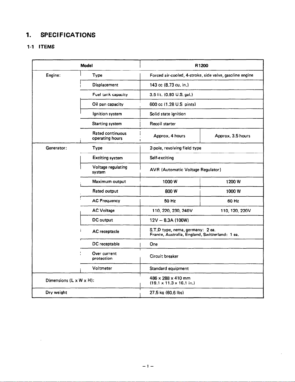
Specifications and Main Features
Engine: R 1200
Model: Forced air-cooled, 4-stroke, side valve gasoline engine
Displacement: 143 cc(8.73 cu.in)
Fuel tank capacity: 3.5 liters (0.93 U.S. gal)
Oil pan capacity: 600 cc (1.28 U.S. pints)
Ignition system: Solid state ignition system
Starting system: Recoil starter
Rated continuous operating hours: Approx.3.5 hours (at rated load of 50 Hz)
Generator type: 2 pole, revolving field type
Exciting system: Self exciting type
Voltage regulating system: AVR(Automatic Voltage Regulator)
Maximum output: 1000 W
Rated output: 800 W (50Hz), 1000 W(60Hz)
Ac frequency: 50 Hz/60 Hz
Ac voltage rating: 110V, 220V, 230V, 240V (50Hz) / 110V, 120V, 220V (60Hz)
Dc output: 12V — 8.3A (100W)
Ac receptacles: 2 ea. (S.T.D type, nema, germany)), 1 ea. (France Australia England Switzerland)
Dc receptacles: One
Over current protection: Circuit breaker
Voltmeter: Standard equipment items
Dimension (Length x Width x Height): 486 x 288 x 410 mm (19.1 x 11.3 x 16.1 in)
Dry weight: 27.5 kg (60.6lbs)
Frequently Asked Questions
Q: What is the fuel tank capacity of the R1200 generator?
A: The fuel tank capacity is 3.5 liters (0.93 U. S. gal).
Q: How long can the generator run on a full tank?
A: Provided the current load is close to that rated for a frequency of 50 Hz, then the generator may be able to last for four hours within a single full tank.
Q: What is the most output power capacity of R1200?
A: The stated limit for all R1200 generators is up to 1000 W.
Q: Can both AC and DC outputs be drawn at the same time?
A: Yes, the generator allows for both AC and DC outputs to be used simultaneously provided the combined output does not exceed the specified capacity.
Q: Which engine is fitted on R1200?
A: It features forced air-cooled 4 stroke gasoline side valve engine.
Q: Calculate the weight of the R1200 generator?
A: Weight without fuel or oil is calculated at 27.5 kg (60.6 lb ).
Q: What are the AC voltage ratings available with the generator?
A: Depending on the frequency, voltages of 110V, 220V, 230V and 240V can be chosen as AC voltage levels.
Q: Which type of ignition system is installed in R1200?
A: The generator has a modern ignition solid state system.
Q: By What means is the generator ignited?
A: The device uses a recoil starter.
Q: Do we need to service the generator?
A:In most cases the generator will not require much attention but it is wise to examine and service the device periodically.
User Manual
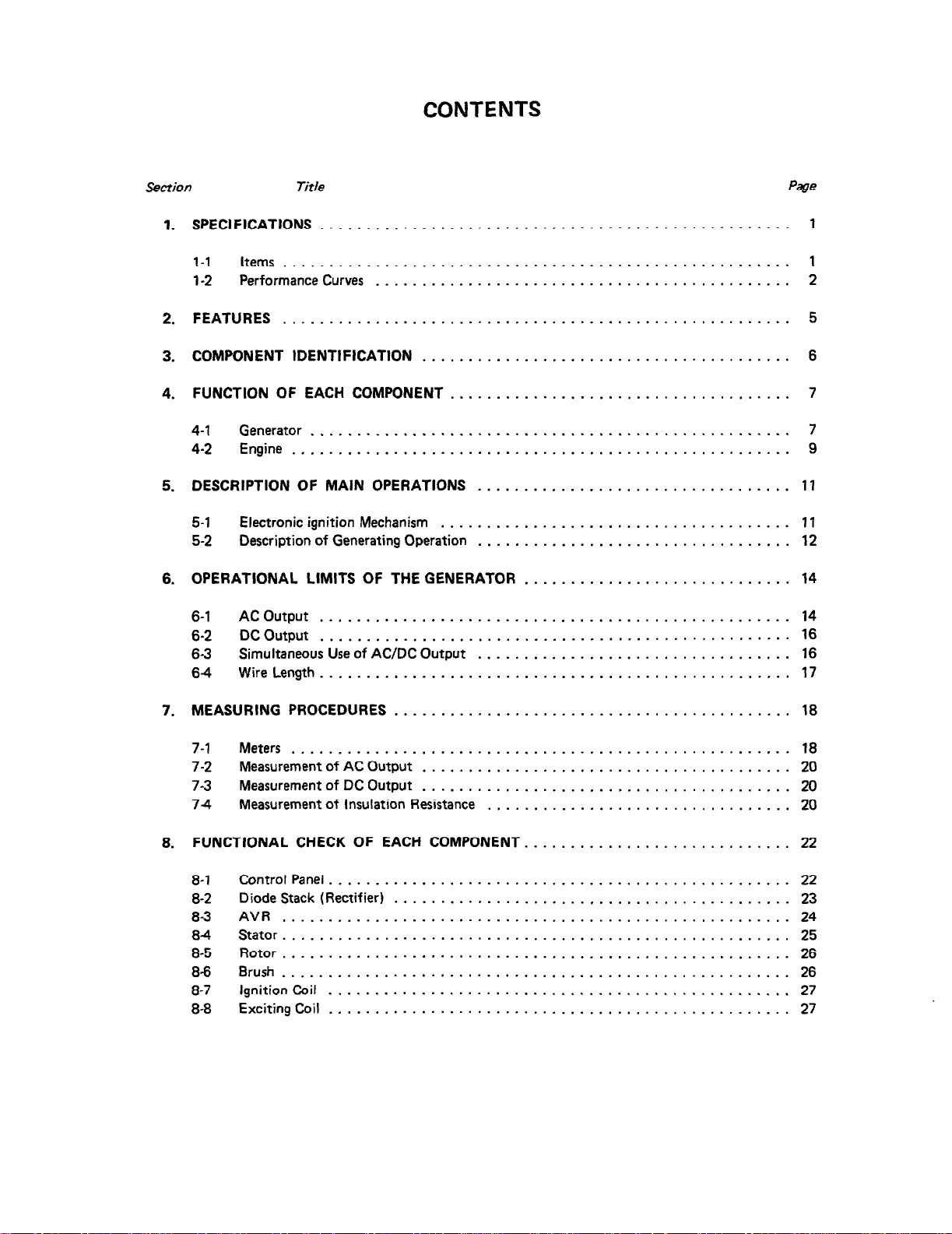
SPECIFICATIONS
l-l ITEMS
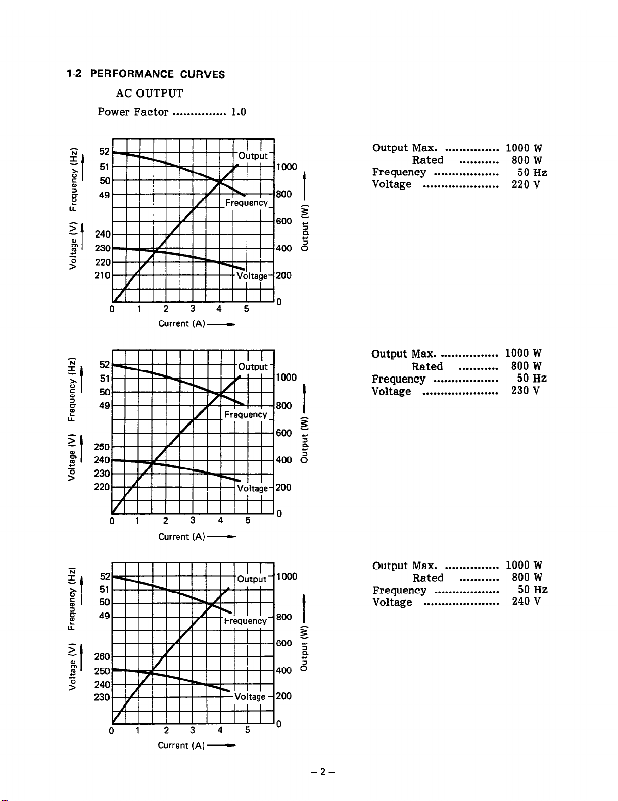
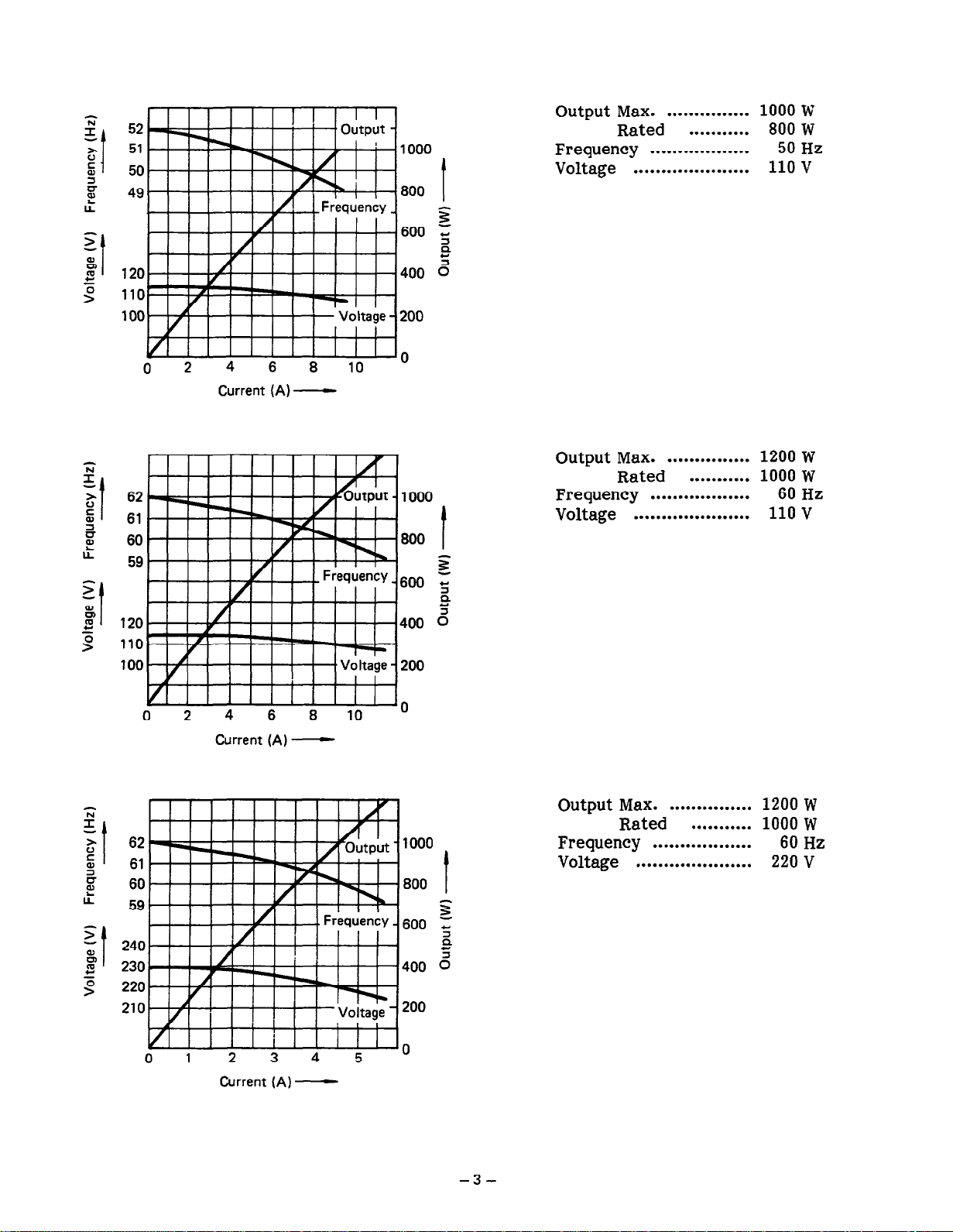
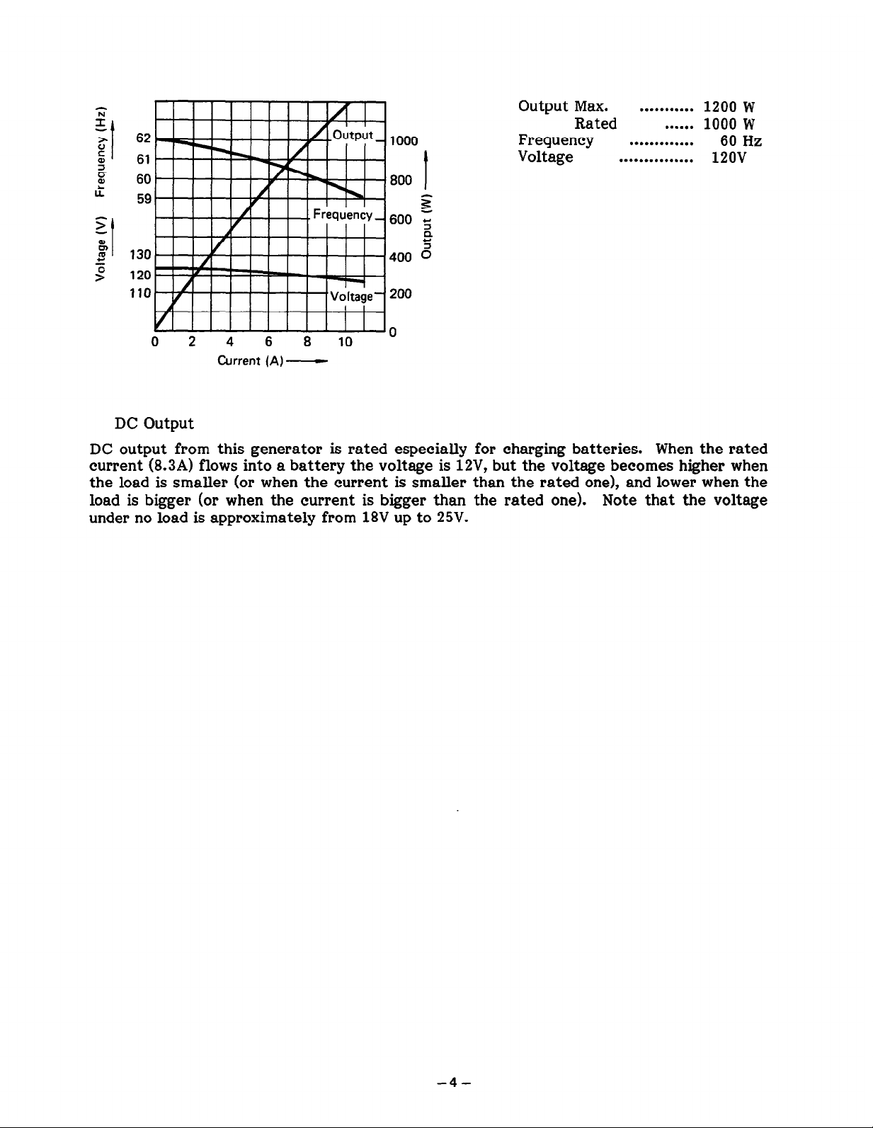
1-2 PERFORMANCE CURVES
FEATURES
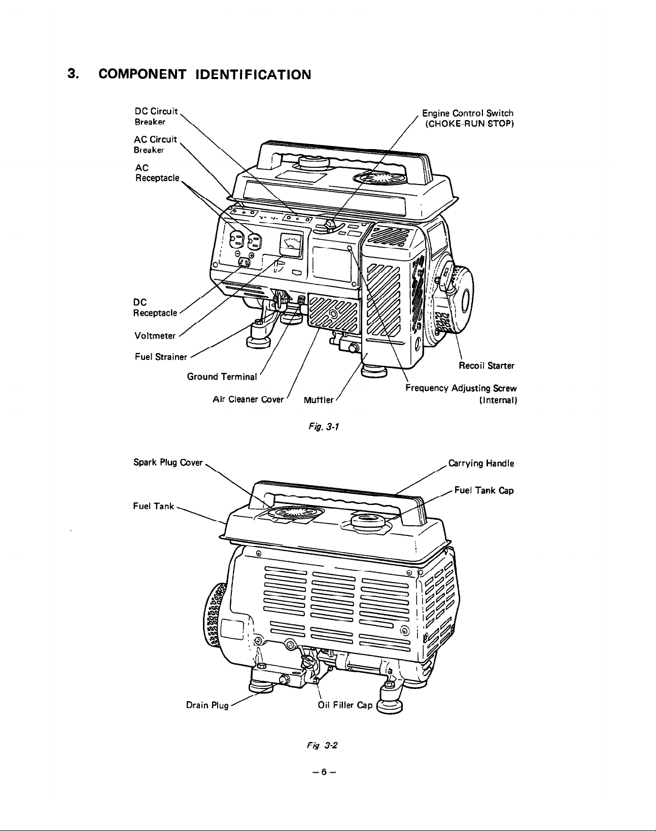
COMPONENT IDENTIFICATION

FUNCTION OF EACH COMPONENT
4-l GENERATOR
4-2 ENGINE
DESCRIPTION OF MAIN OPERATIONS
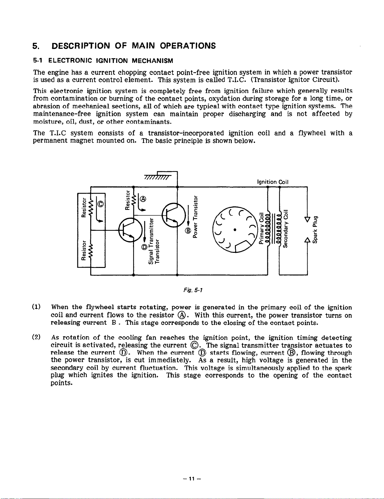
5-l ELECTRONIC IGNITION MECHANISM
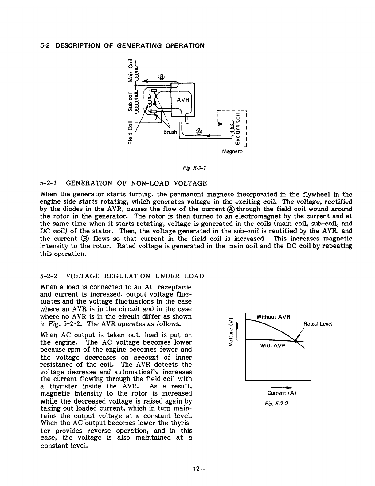
5-2 DESCRIPTION OF GENERATING OPERATION
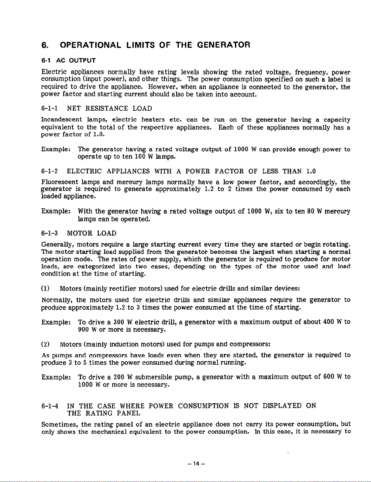
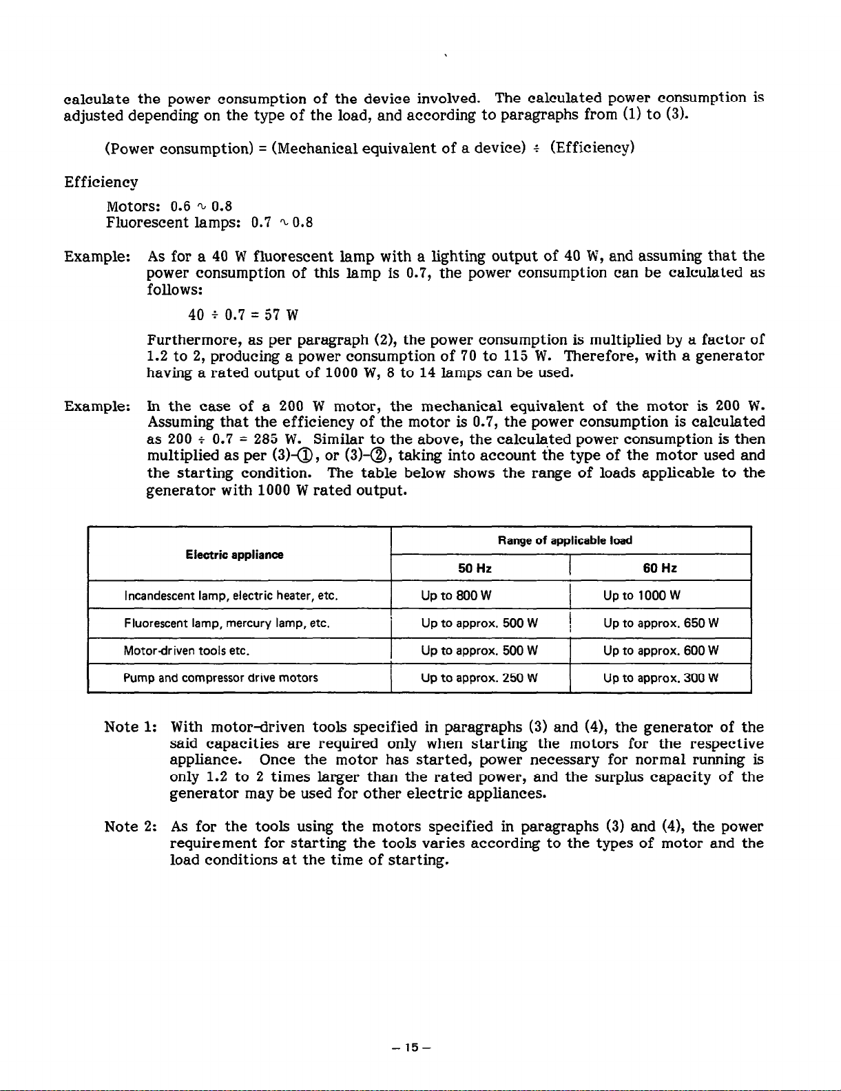
OPERATIONAL LIMITS OF THE GENERATOR
6-1 AC OUTPUT
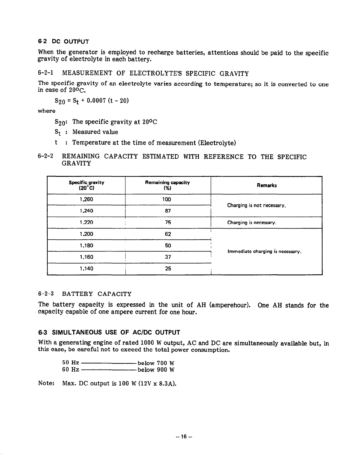
6-3 SIMULTANEOUS USE OF AC/DC OUTPUT
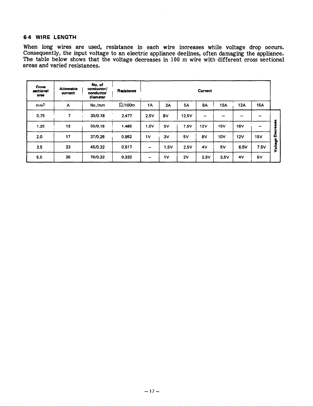
64 WIRE LENGTH
MEASURING PROCEDURES
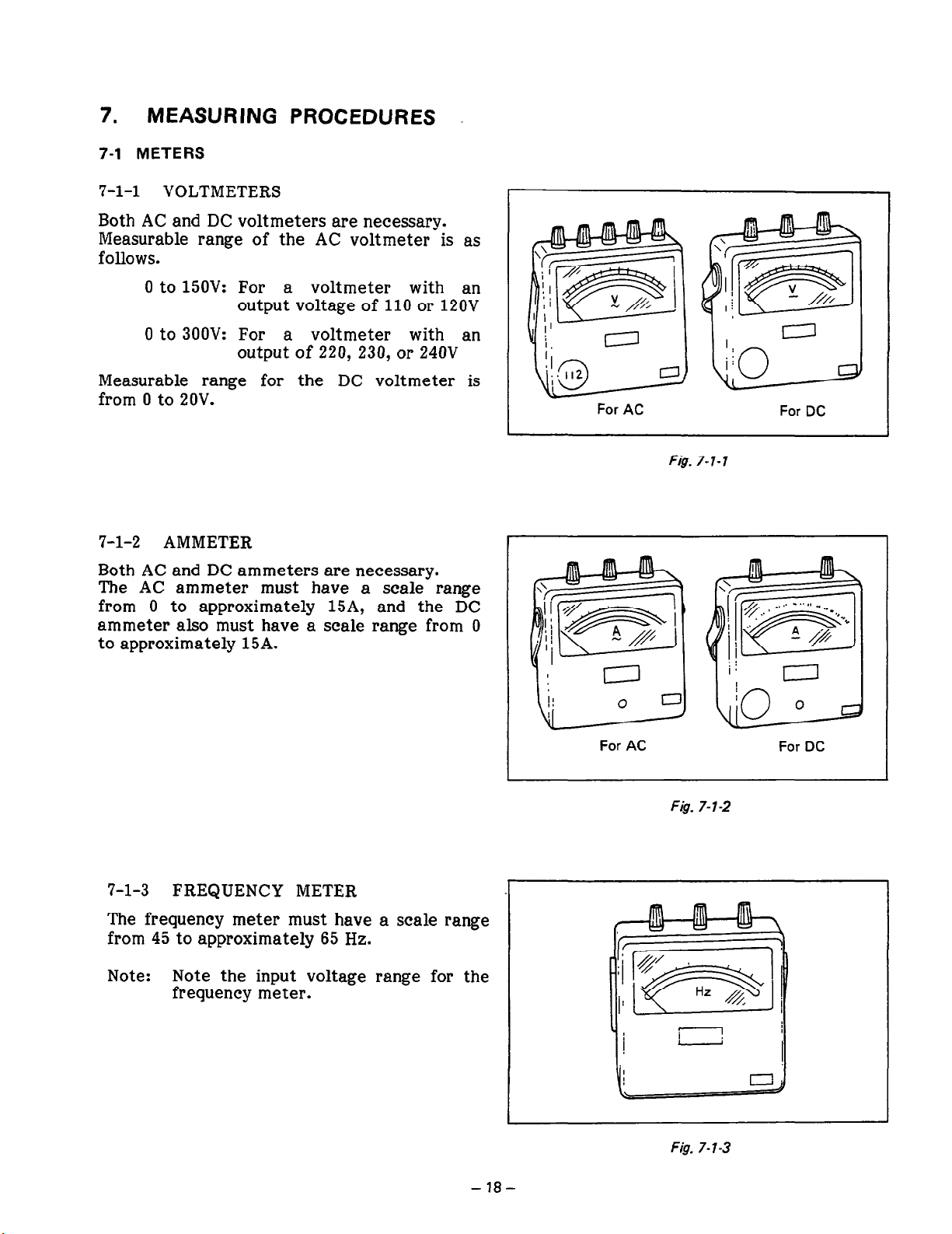
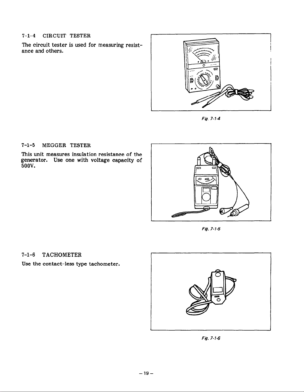
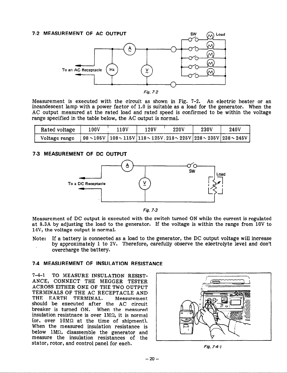
7-1 METERS
73 MEASUREMENT OF DC OUTPUT
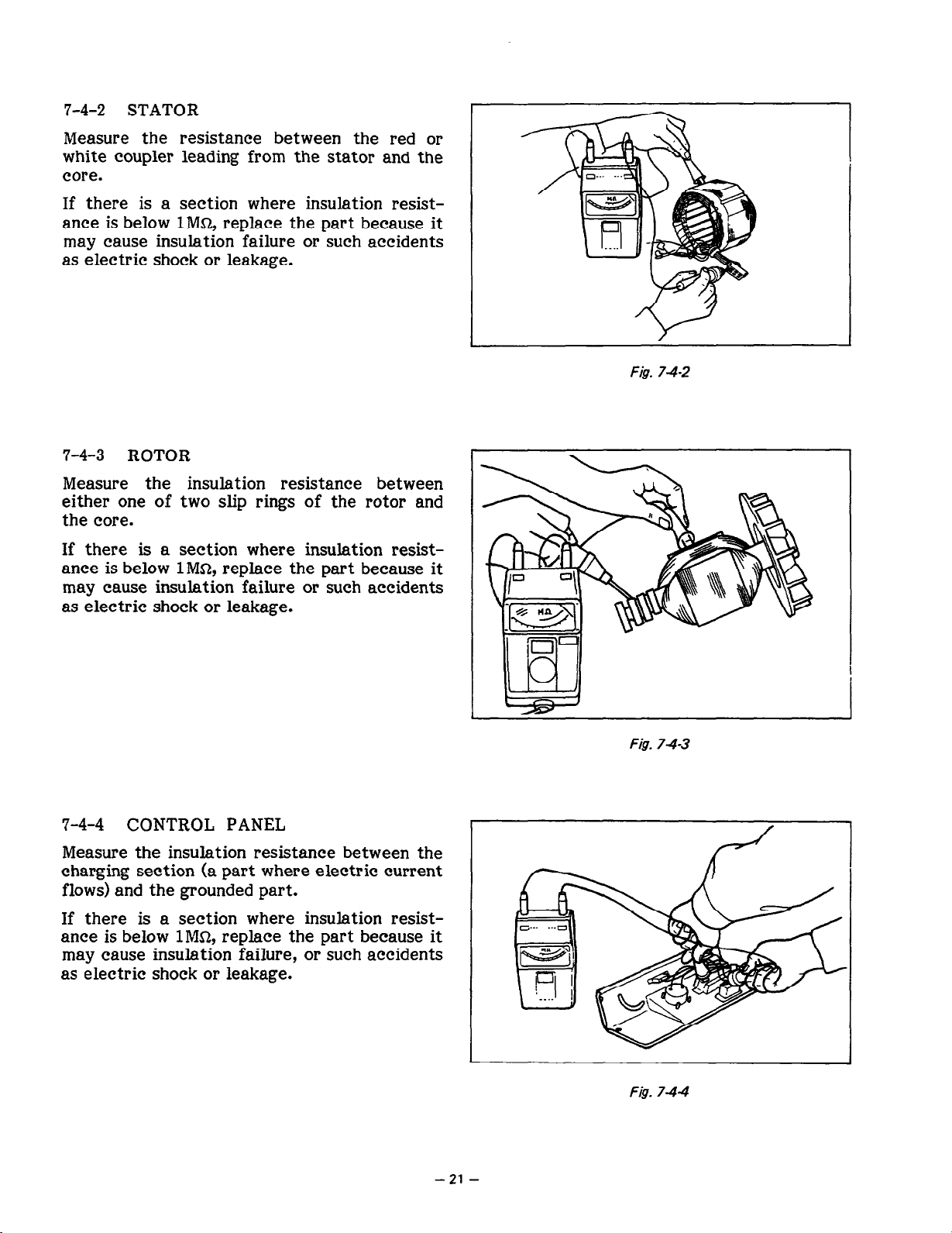
7-4 MEASUREMENT OF INSULATION RESISTANCE
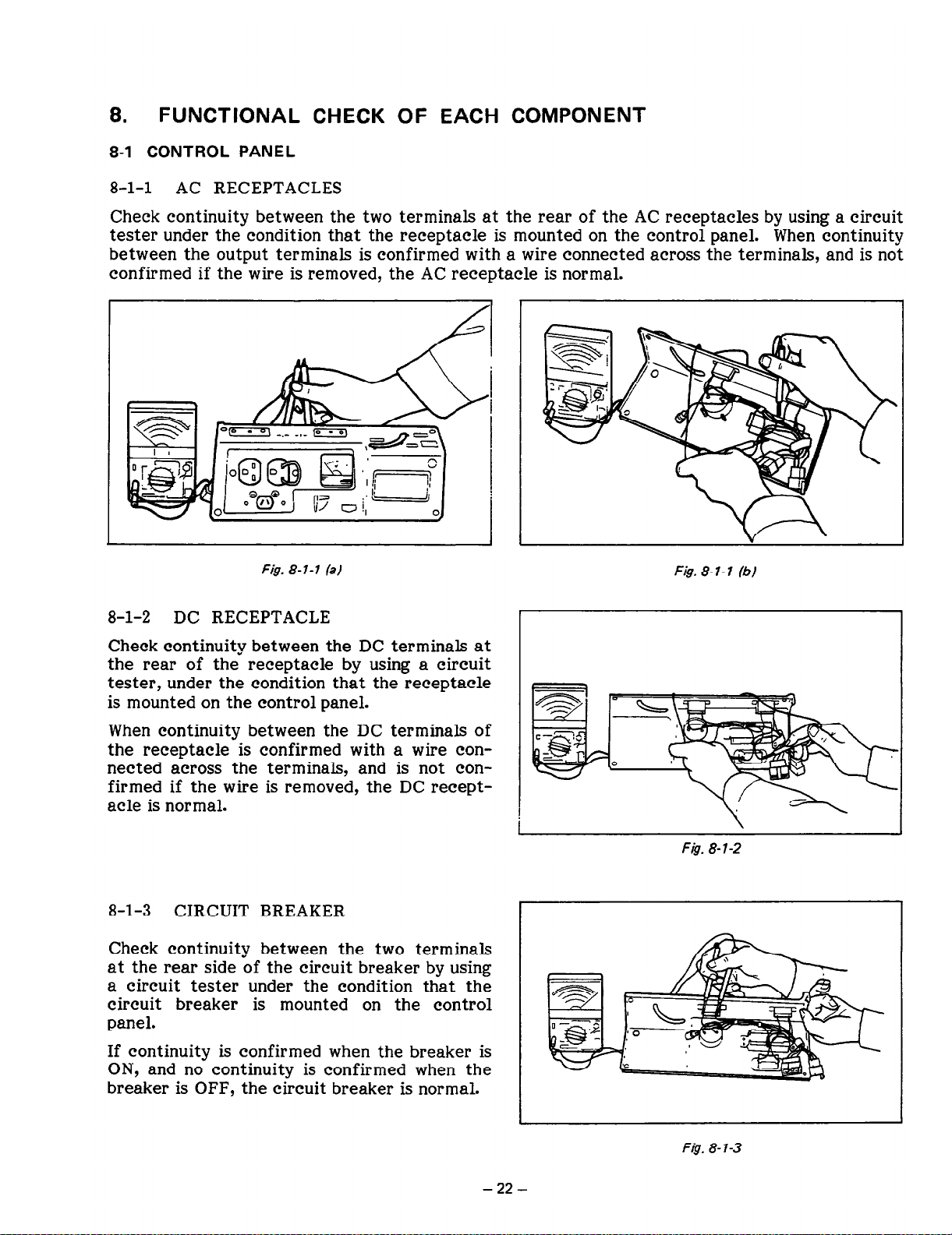
FUNCTIONAL CHECK OF EACH COMPONENT
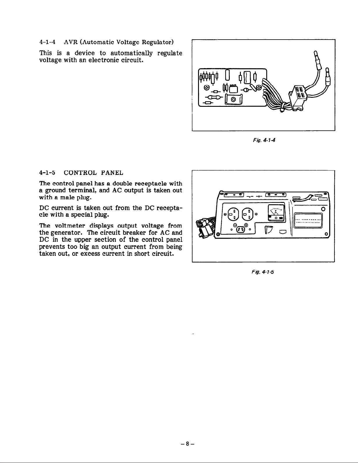
8-1 CONTROL PANEL
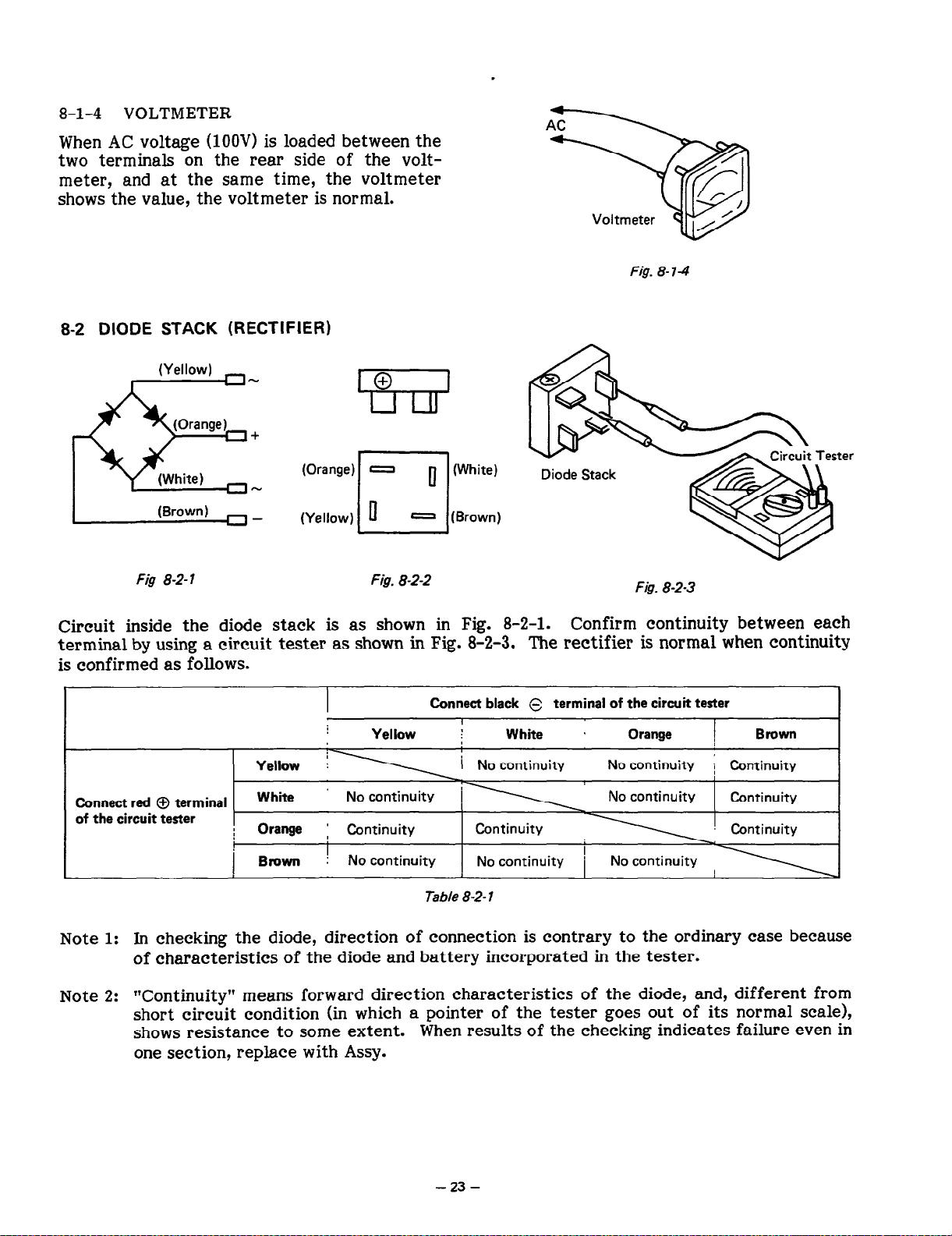
8-2 DIODE STACK (RECTIFIER)
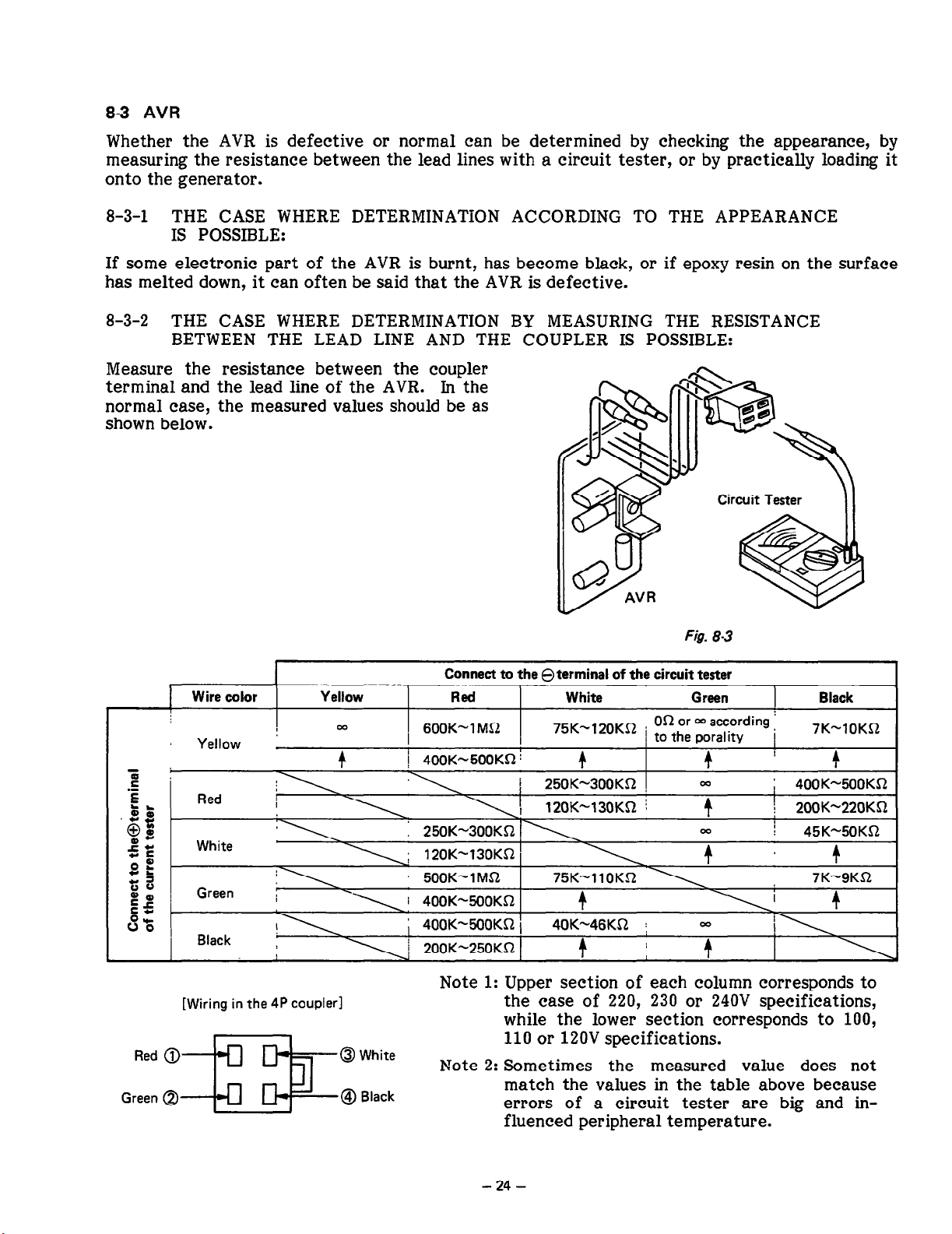
83 AVR
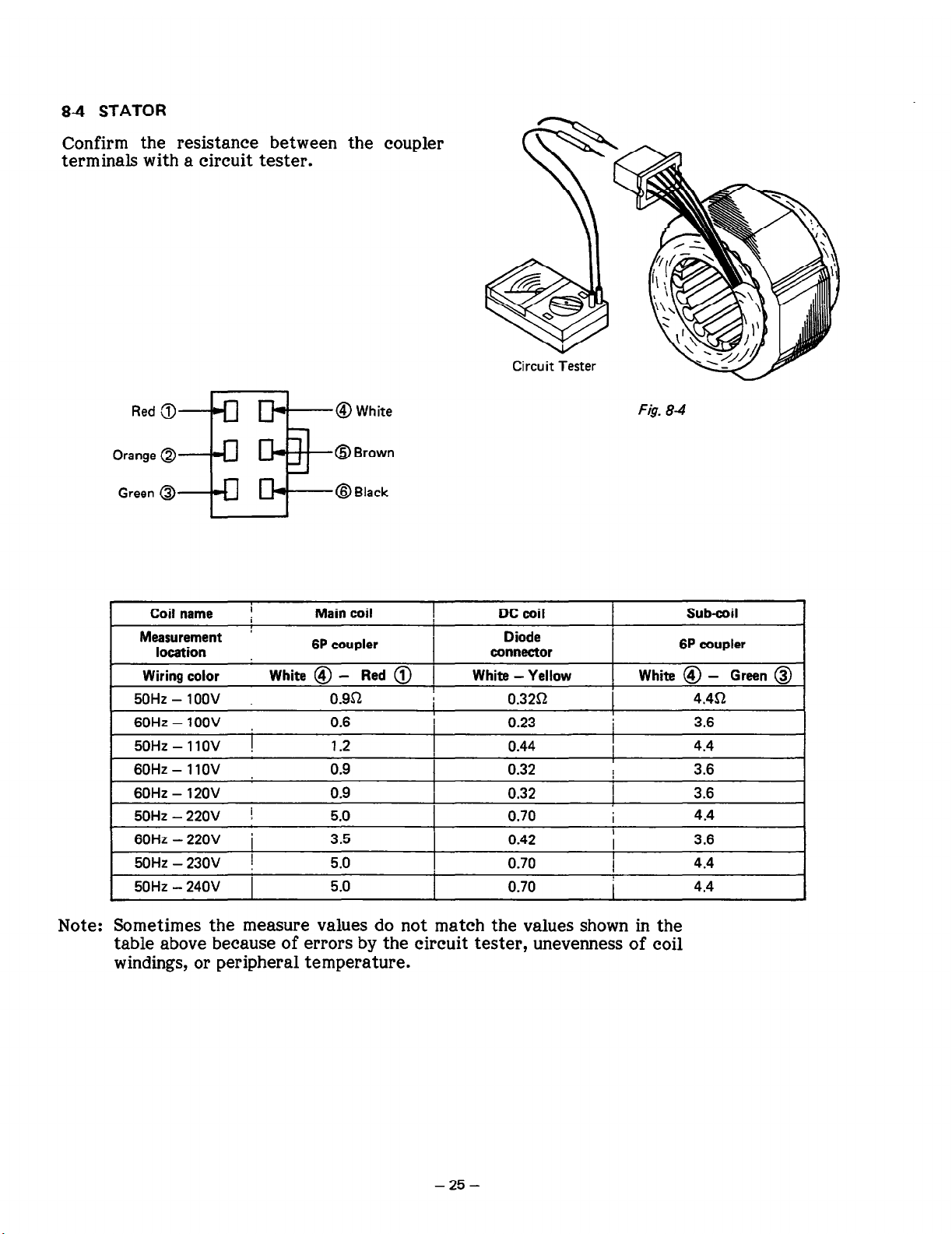
84 STATOR
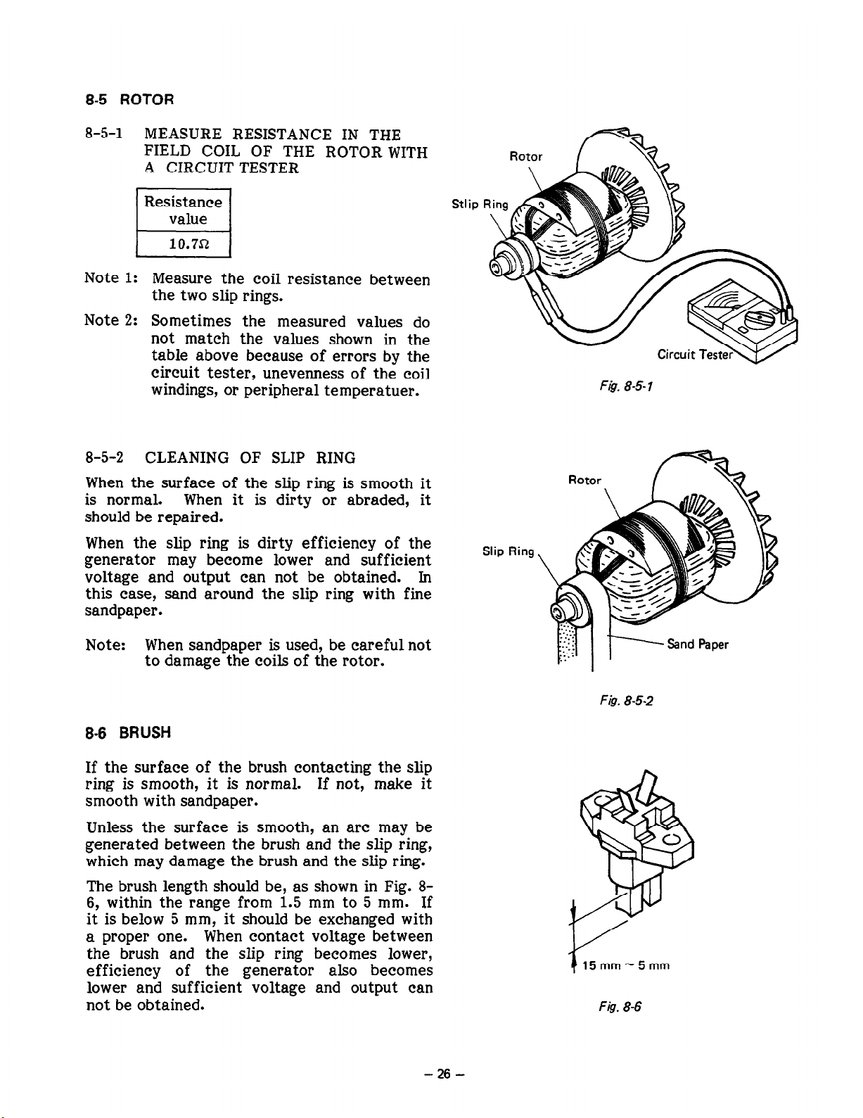
8-5 ROTOR
8-6 BRUSH

8-7 IGNITION COIL
8-8 EXCITING COIL

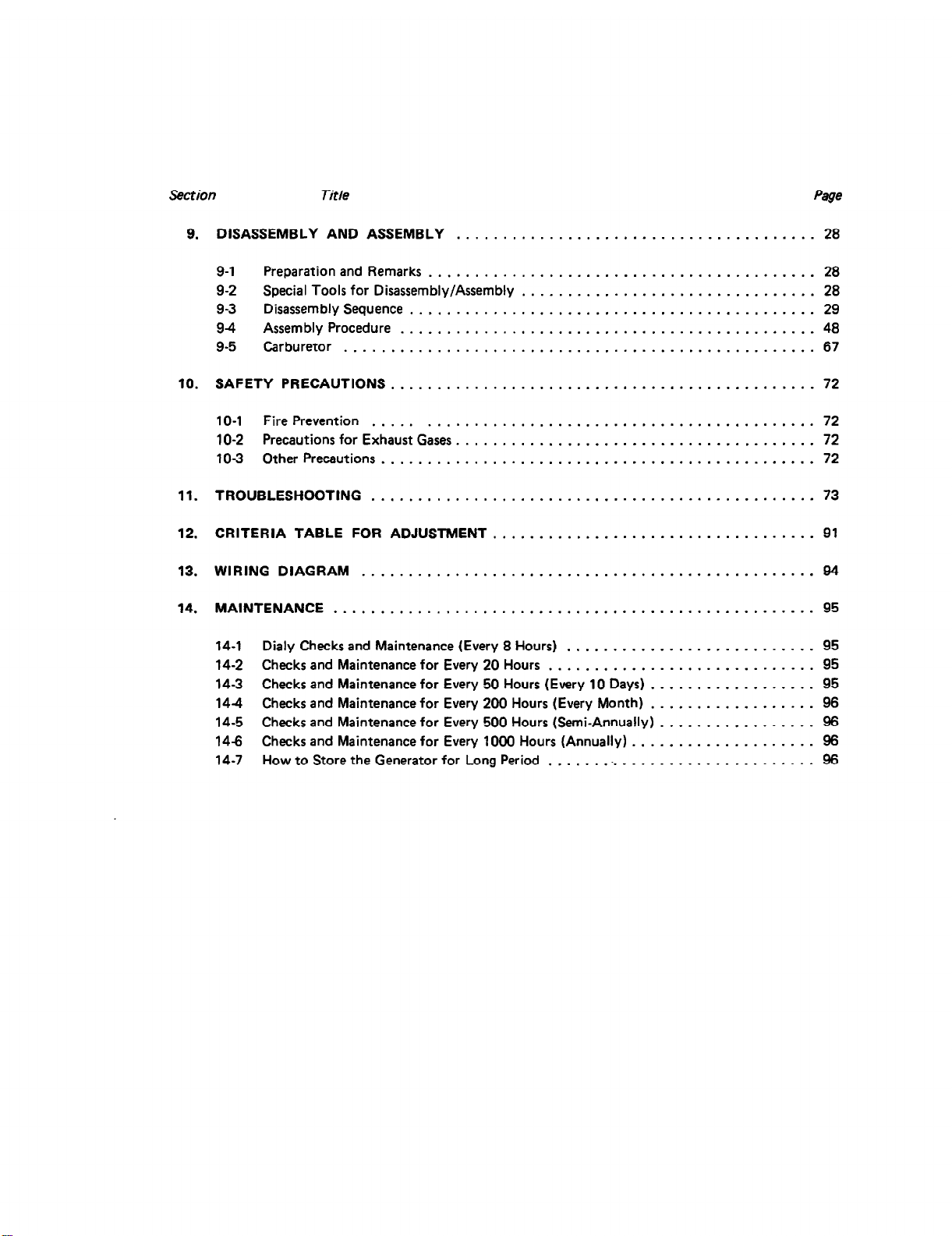
DISASSEMBLY AND ASSEMBLY
9-2 SPECIAL TOOLS FOR DISASSEMBLY/ASSEMBLY

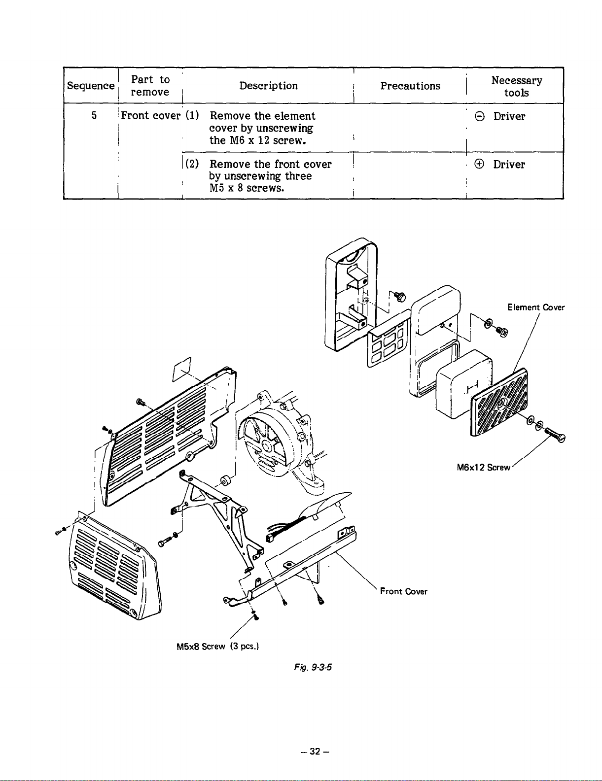
9-3 DISASSEMBLY SEQUENCE


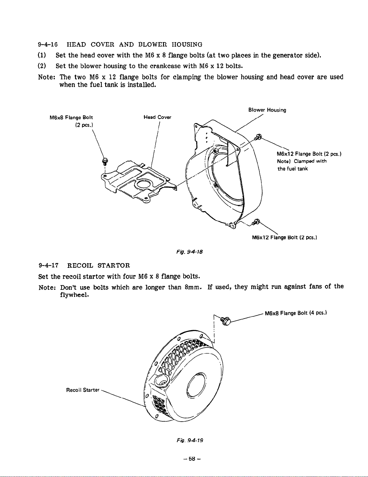
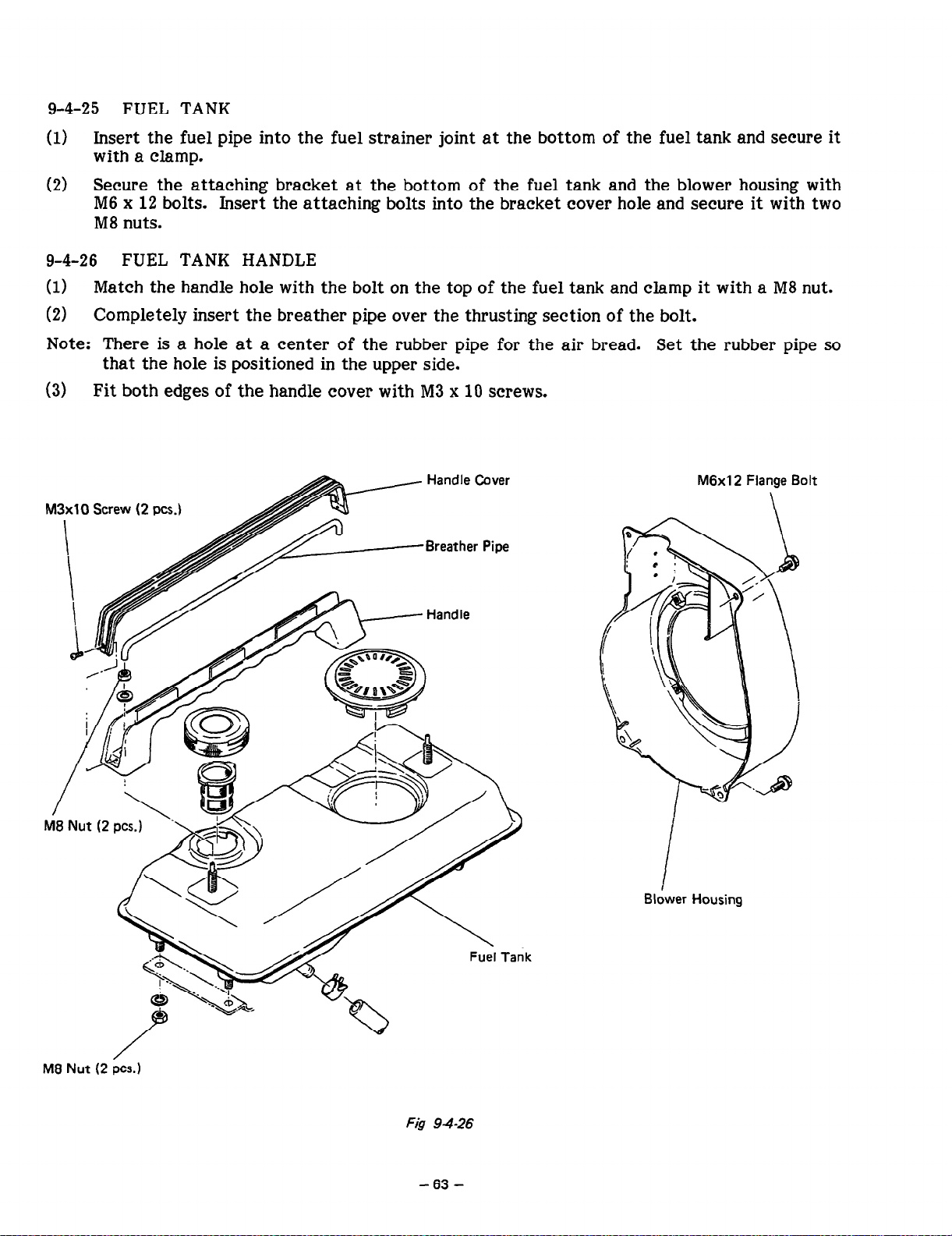
9-4 ASSEMBLY PROCEDURE


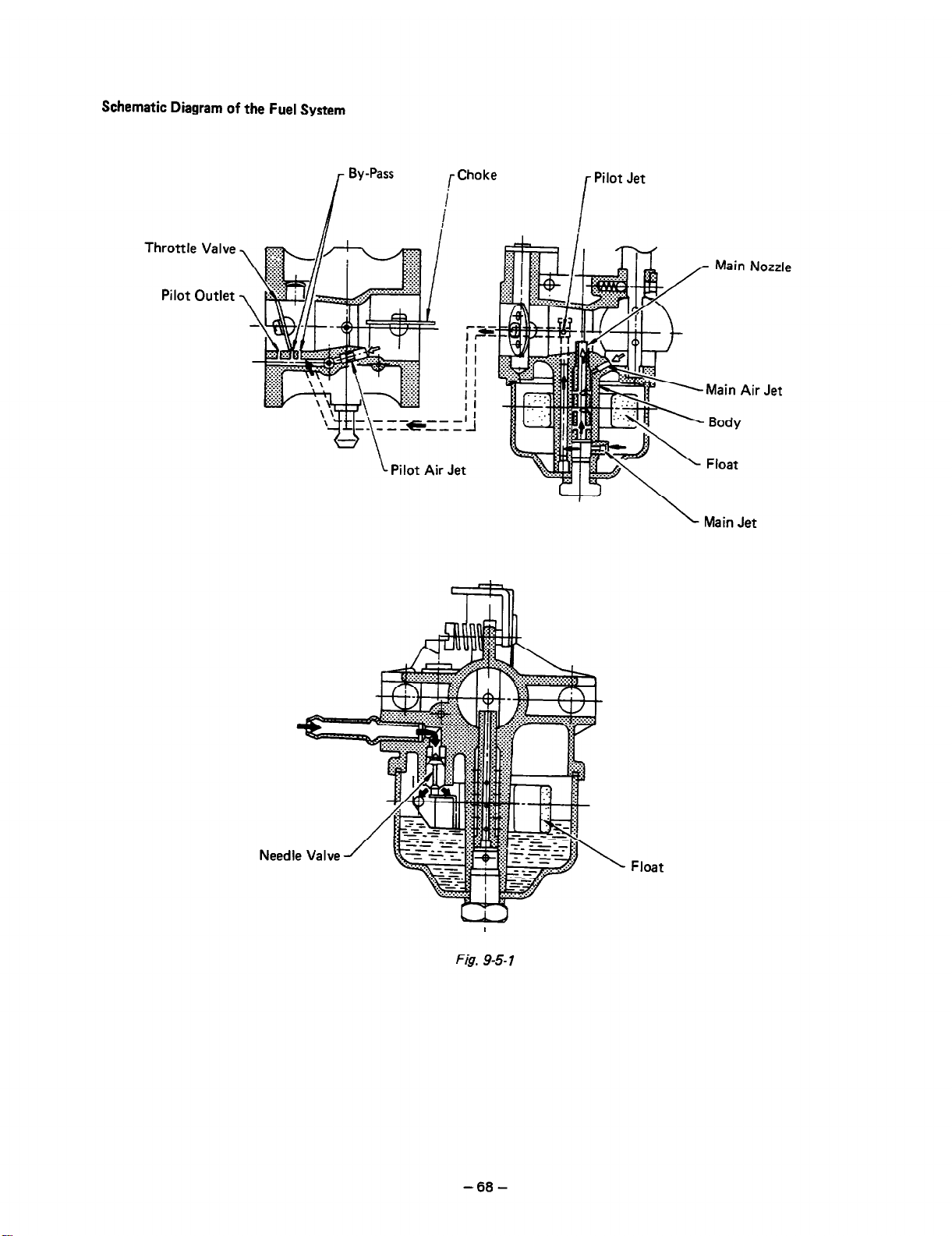
9-5 CARBURETOR


SAFETY PRECAUTIONS
10-l FIRE PREVENTION
10-2 PRECAUTIONS FOR EXHAUST GASES
103 OTHER PRECAUTIONS

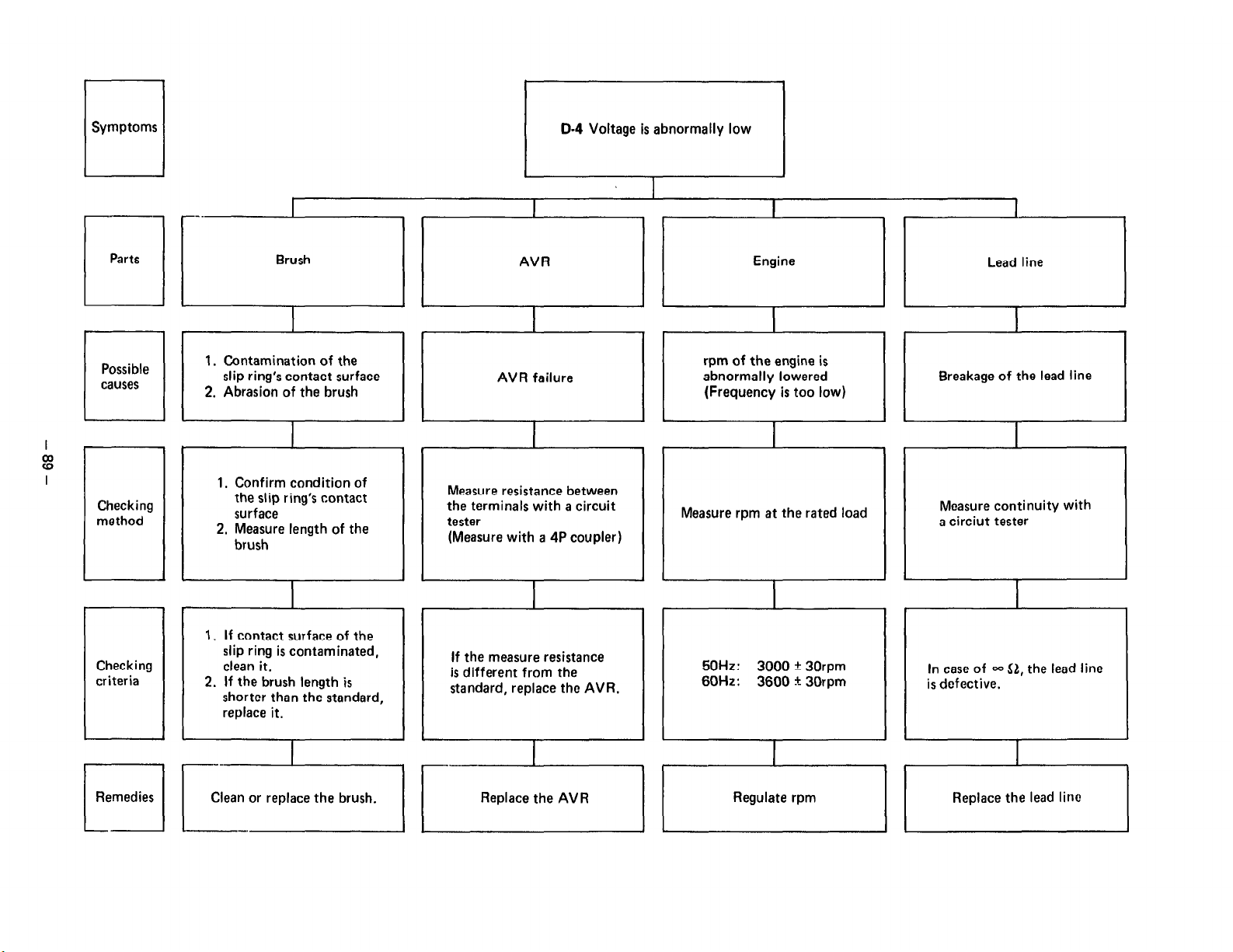
TROUBLESHOOTING


CRITERIA TABLE FOR ADJUSTMENT


WIRING DIAGRAM

MAINTENANCE
14-1 DAILY CHECKS AND MAINTENANCE (EVERY 8 HOURS)
14-2 CHECKS AND MAINTENANCE FOR EVERY 20 HOURS
14-3 CHECKS AND MAINTENANCE FOR EVERY 50 HOURS (EVERY 10 DAYS)

144 CHECKS AND MAINTENANCE FOR EVERY 200 HOURS (EVERY MONTH)
14-5 CHECKS AND MAINTENANCE FOR EVERY 500 HOURS (SEMI-ANNUALLY)
14-5 CHECKS AND MAINTENANCE FOR EVERY 1000 HOURS (ANNUALLY)
 Loading...