


PARTS
MANUAL
Model
RGX7800
GENERATOR
PUB-GP6801
Rev. 07/09

Robin America, Inc.
905 Telser Road • Lake Zurich, IL 60047 • Phone: 847-540-7300 • Fax: 847-438-5012
e-mail: sales@robinamerica.com • www.subarupower.com
© Copyright 2009 Robin America, Inc.

HOW TO USE THIS MANUAL
Robin engines are identifi ed by MODEL, SPECIFICATION, and CODE NUMBER. For each
model there may be many different versions called specifi cations. Each specifi cation will be
unique in some way. The difference may only be the paint color or it may have a different
type of PTO or some other signifi cant difference.
In order the identify the correct service part number, it is important to confi rm the specifi ca-
tion and code numbers for your engine. The specifi cation and code number together are
know as the PRODUCT NUMBER.
All Robin 4 cycle engines have a Product Number label similar to the label illustrated below.
The Product Number Label has a 15 digit alphanumeric string that consists of the
SPECIFICATION (SPEC) number (11 digits) and the CODE number (4 digits). Please
note the illustration below:
E X 4 0 0
SPEC NO. (11 digits) CODE NO. (4 digits)
PRODUCT NO. (15 digits)
RGX7800 - 3 - 07-09
X X X X
MANUAL LAYOUT
1
2
1
6
4
3
7
9
2
3
5
4
8
1. SECTION NAME Parts are broadly classifi ed according to their functions.
Refer to the Group Index (table of contents) for respective section name.
2. FIG. No. The FIG. number indexes the reference and part numbers to the illustration. Figure numbers
that vary only in the tens place (i.e..: 700 and 710) are in a group of the same section
(i.e..:Electrical Device Group).
3. REF. No . The Reference number identifi es the part illustration with the corresponding part number in the
part list.
4. SUBASSEMBLY SUBASSEMBLY parts of part assembly are listed below the assembly part. The subassembly
part reference number is indicated by the number led by "-" such as "-1", "-2".
5. PART NUMBER It is the number assigned for sales unit. Use the PART No. when making an order.
6. DESCRIPTION It is designation of the part.
7. QTY. Quantity of each part used for each product.
8. REMARKS This gives a distinctive feature and/or a supplementary comment for the type, the specifi cation,
and the part concerned. It also shows part number(s) interchangeable for the part.
9. FROM-TO This section shows the CODE No. to indicate the history of progress in which improved parts
have been introduced in the product. The FROM-TO CODE No. helps to identify PART No.
being employed in the product concerned. See the examples below:
- The part is used in the product irrespective of CODE No.
2101- The part is used in the products with CODE No. of 2101 and after this number.
- 2100 The part is used in the products with CODE No. of 2100 and before this number.
RGX7800 - 4 - 07-09

GROUP INDEX
Group Name Page
CRANKCASE GROUP ...............................................................................6
CRANKSHAFT GROUP .............................................................................8
INTAKE and EXHAUST GROUP ..............................................................10
GOVERNOR GROUP ..............................................................................14
COOLING and STARTING GROUP ......................................................... 16
FUEL, LUBRICANT GROUP .................................................................... 18
CARBURETOR GROUP .......................................................................... 20
ELECTRIC DEVICE GROUP .................................................................. 22
GENERATOR GROUP ............................................................................. 30
INDEX OF DESCRIPTION SYMBOLS
SYMBOL DESCRIPTION
AY ...........................ASSEMBLY
CP ...........................COMPLETE
EX ...........................EXPORT (from Japan)
FIG. .........................FIGURE
FR. ..........................FRONT
" ..............................INCH
INCL. ......................INCLUDE
~L ............................LITER
L= ...........................LENGTH (in. mm)
L.H. (LH) .................LEFT-HAND SIDE
MECH .....................MECHANICAL
NO (NON) ...............NONE
OPT.........................OPTIONAL
O.S. ........................OVER SIZE
SYMBOL DESCRIPTION
P= ...........................PITCH (in mm)
P.T.O. (PTO) ...........POWER TAKE OFF
REF. ........................REFERENCE
R.H. (RH) ................RIGHT HAND SIDE
RR. .........................REAR
STD. .......................STANDARD
SW ..........................SWITCH
T= ...........................THICKNESS (in mm)
UN ..........................UNIT
U.S..........................UNDER SIZE
~V ...........................VOLT AGE
~W ..........................WA TT
W/ ...........................WITH
W/O ........................WITHOUT
RGX7800 - 5 - 07-09
SECTION 1 CRANKCASE GROUP
FIG. 100
20
60
610
28
270
280
220
620
250
210
631
260
230
630
27
690
26
40
50
70
680
710
10
75
30
700
90
80
300
RGX7800 - 6 - 07-09

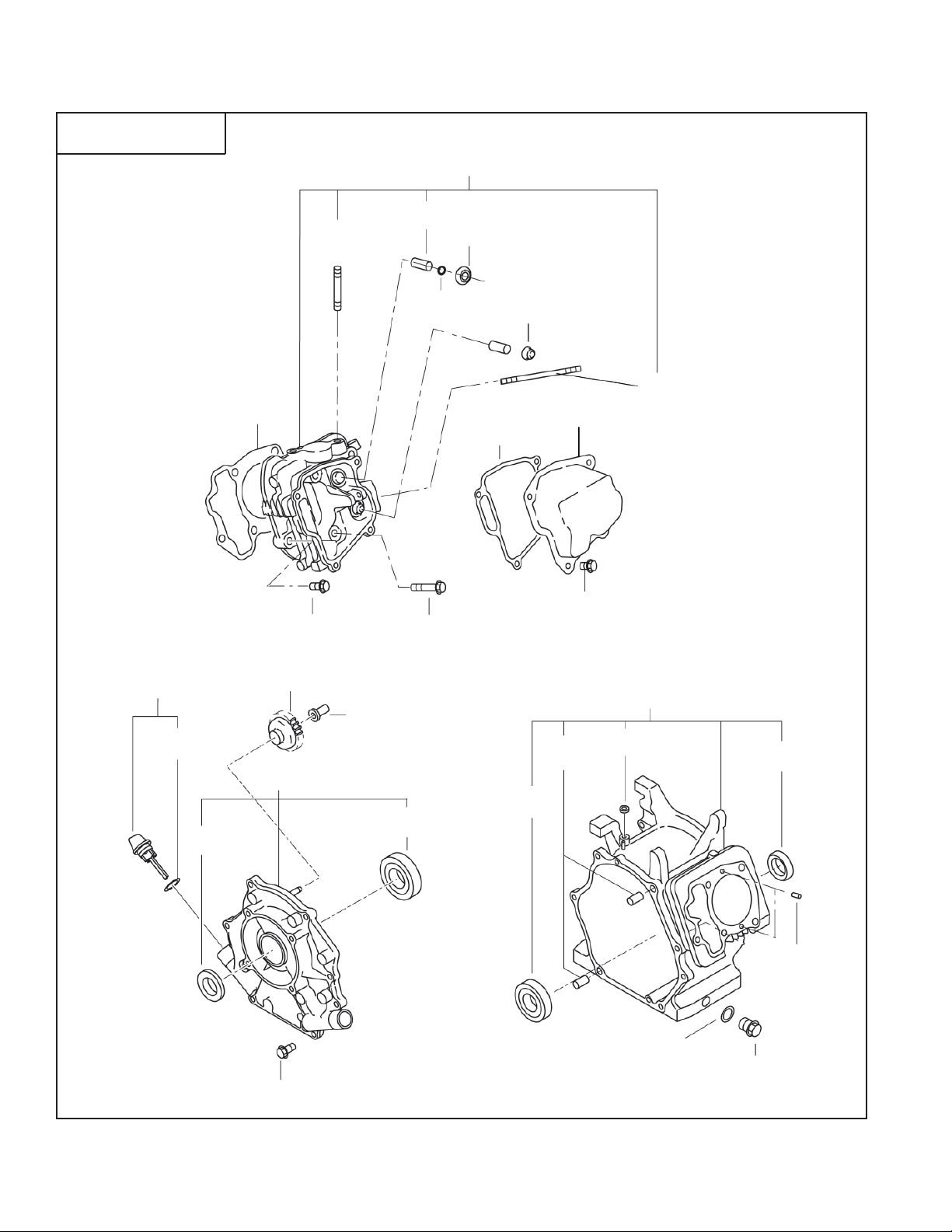
SECTION 1 CRANKCASE GROUP
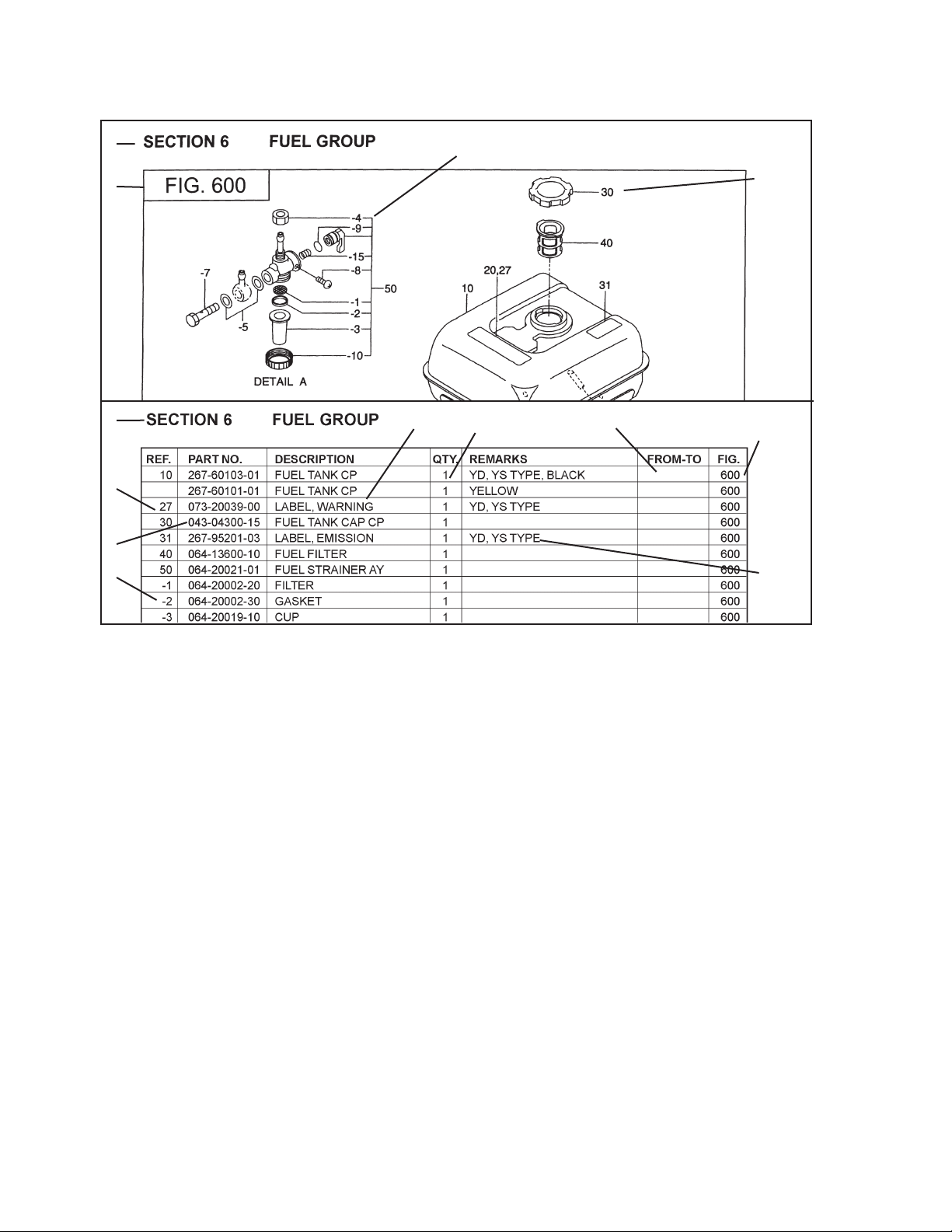
REF. PART NO. DESCRIPTION QTY. REMARKS FROM-TO FIG.
10 20B-10104-31 Crankcase Cp 1 100
20 20B-14202-03 Valve Guide 2 100
26 132-11AA1-10 Seal, intake valve 1 100
27 056-51000-50 Clip 1 100
28 263-35341-03 Retainer Plate 1 100
30 044-03500-90 Oil Seal 1 100
40 060-03502-40 Ball Bearing 1 100
50 277-15001-03 Pipe Knock 2 100
60 010-50802-90 Stud 2 100
70 010-50603-51 Stud 2 100
75 044-00800-10 Oil Seal 1 100
80 040-11400-30 Plug 1 100
90 021-11400-20 Gasket 1 100
210 20B-11004-11 Mainbearing Cover Cp 1 100
220 044-03500-90 Oil Seal 1 100
230 060-03502-40 Ball Bearing 1 100
250 20B-45003-01 Governor Gear Cp 1 100
260 277-41901-03 Governor Sleeve 1 100
270 279-63601-30 Oil Gauge Ay 2 100
280 279-63601-08 Gasket 2 100
300 011-00803-40 Flange Bolt 8 100
610 20B-13001-01 Cylinder Head Cp 1 100
620 20B-15001-03 Gasket, head 1 100
630 011-01000-40 Flange Bolt 4 100
631 001-04083-50 Flange Bolt 2 100
680 20B-15501-01 Rocker Cover Cp 1 100
690 20B-16001-03 Gasket, rocker cover 1 100
700 031-00600-10 Dowel Pin 2 100
710 011-00600-20 Flange Bolt 4 100
960 20B-99001-07 Gasket Set 1 100
RGX7800 - 7 - 07-09

SECTION 2 CRANKSHAFT GROUP
FIG. 200
310
320
10
380
350
70
360
370
RGX7800 - 8 - 07-09

SECTION 2 CRANKSHAFT GROUP
REF. PART NO. DESCRIPTION QTY. REMARKS FROM-TO FIG.
10 20B-20701-01 Crankshaft Cp 1 200
70 005-32054-01 Woodruff Key 1 200
310 20B-22501-00 Connecting Rod Ay 1 200
320 001-05084-00 Flange Bolt 2 200
350 263-23301-33 Piston Pin 1 200
360 20B-23401-H3 Piston 1 200
370 20B-23501-07 Piston Ring Set 1 200
380 056-52100-20 Clip 2 200
RGX7800 - 9 - 07-09

SECTION 3 INTAKE and EXHAUST GROUP
FIG. 300
405
415
340
350
241
225
231
27
25
80
90
290
170
60
70
150
95
200
202
240
230
220
160
163
37
35
RGX7800 - 10 - 07-09
38
34
10
166

SECTION 3 INTAKE and EXHAUST GROUP
REF. PART NO. DESCRIPTION QTY. REMARKS FROM-TO FIG.
10 20B-31602-00 Camshaft Cp 1 300
25 20B-35101-11 Pin Cp, camshaft 1 300
27 024-00700-20 O Ring 1 300
34 005-19041-00 Spring Pin 2 300
35 277-36401-03 Release Lever 1 300
37 20B-36501-03 Clip 1 300
38 20B-38701-03 Return Spring 1 300
60 246-33611-03 Valve Spring 2 300
70 246-33711-13 Spring Retainer 2 300
80 20B-33401-H3 Intake Valve 1 300
90 20B-33501-H3 Exhaust Valve 1 300
95 246-35501-03 Collet Valve 4 300
150 20B-35601-H1 Timing Chain Cp 1 300
160 277-36911-03 Tentioner 1 300
163 277-37101-03 Spring, tentioner 1 300
166 277-36902-03 Pin, tentioner 1 300
170 277-36913-13 Chain Guide 1 300
200 20B-35001-01 Pin Cp, rocker 1 300
202 003-13060-00 Clip 1 300
220 20B-36101-00 Rocker Arm Ay , intake 1 300
225 20B-36102-10 Rocker Arm Ay , exhaust 1 300
230 014-90500-20 Adjust Screw 1 300
231 014-90500-20 Adjust Screw 1 300
240 017-00500-30 Nut 1 300
241 017-00500-30 Nut 1 300
290 011-00600-10 Flange Bolt 1 300
340 20B-35201-03 Gasket, muffl er 1 300
350 980-20082-80 Flange Nut 2 300
405 20B-34001-01 Exhaust Pipe Cp 1 300
415 010-50802-90 Stud 2 300
RGX7800 - 11 - 07-09
SECTION 3 INTAKE and EXHAUST GROUP
FIG. 330
580
570
265
-220
850
-200
510
520
-250
-260
270
RGX7800 - 12 - 07-09

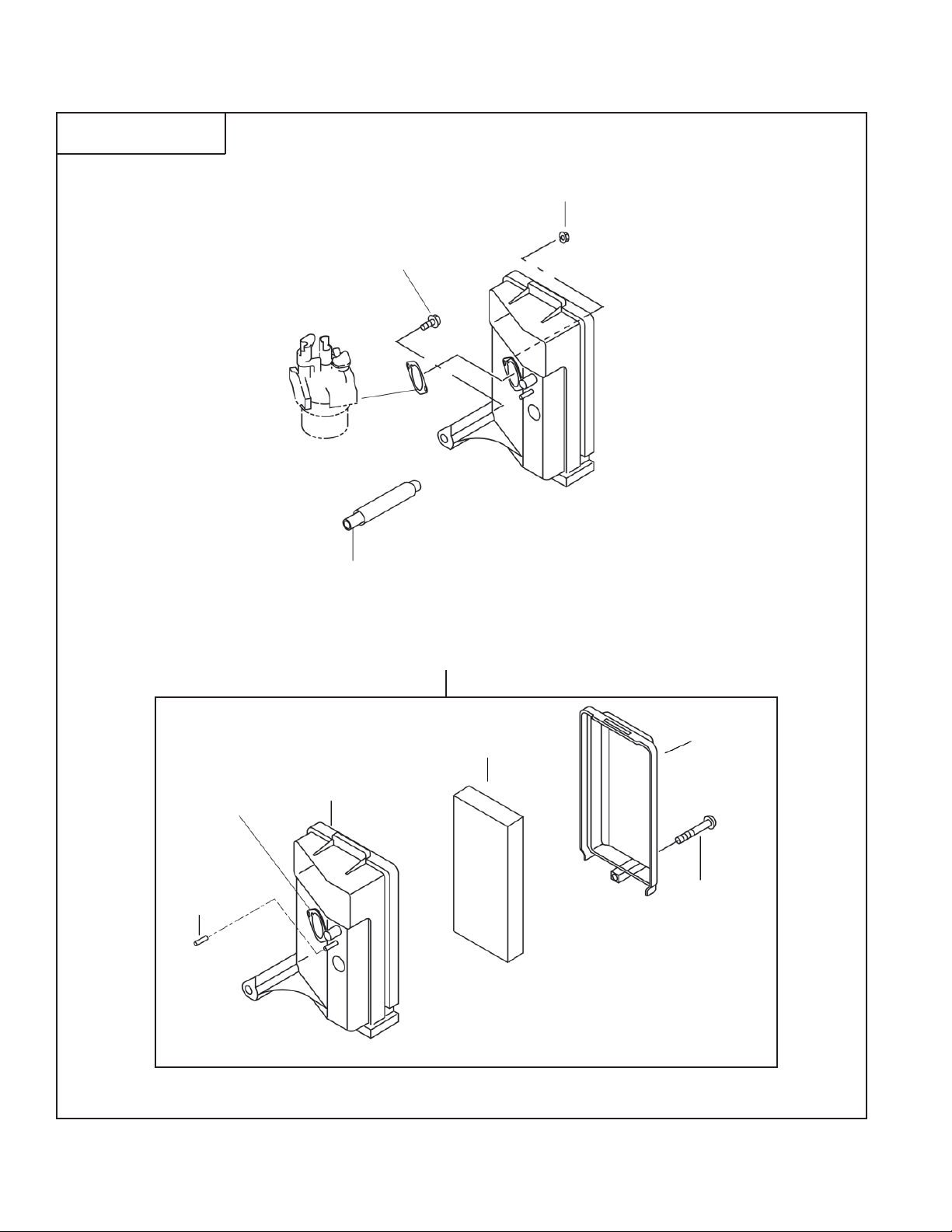
SECTION 3 INTAKE and EXHAUST GROUP
REF. PART NO. DESCRIPTION QTY. REMARKS FROM-TO FIG.
265 20B-32850-H8 Cap 1 330
270 20B-32650-H8 Bolt 1 330
510 20B-32622-H0 Air Cleaner Ay 1 330
-200 20B-32630-H8 Body Cp 1 330
-220 20B-32720-H8 Packing 1 330
-250 20B-32640-H8 Cover Cp 1 330
520 20B-32611-H8 Element 1 330
570 002-38060-00 Flange Nut 2 330
580 001-04061-60 Flange Bolt 1 330
850 X85-11001-70 Rubber Pipe 1 330
RGX7800 - 13 - 07-09
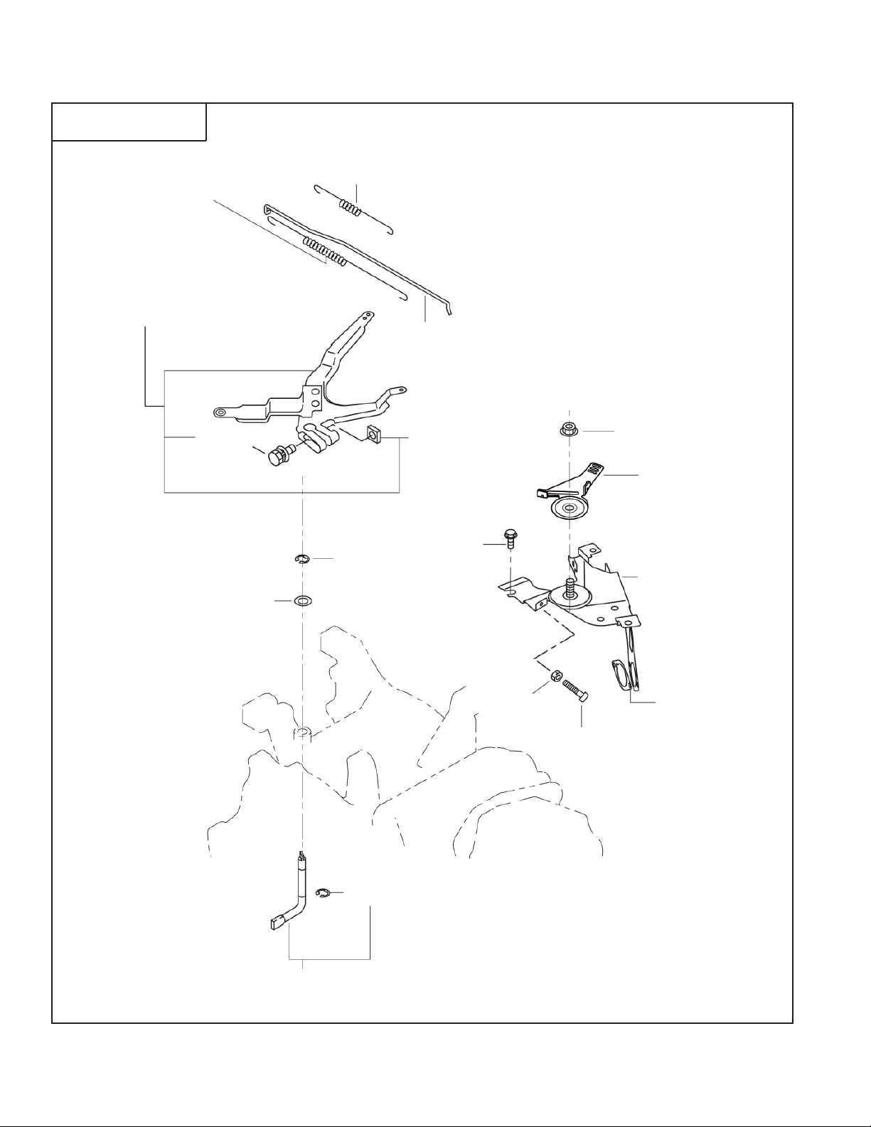
SECTION 4 GOVERNOR GROUP
FIG. 400
80
40
10
30
60
90
50
70
485
370
450
310
435
436
360
50
20
RGX7800 - 14 - 07-09
 Loading...