

Subaru R650 Service Manual
PUB-GS0455
Rev. 8/98

CONTENTS
Section Title
1
.
SPECIFICATIONS
2
.
PERFORMANCE CURVES
2-1 AC Output
2-2 DCOutput
3
.
FEATURES
4
.
GENERAL DESCRIPTION
4-1 Component Identification
4-2 Location of Serial Number. Specification and
Specification Number
5
.
CONSTRUCTION AND FUNCTION OF THE GENERATOR
5-1 Construction
5-2 Function of Each Component
5-3 Description of Generator Operation
5-4 Electronic Ignition System
6 . SAFETY PRECAUTlONS
7
.
RANGE OF APPLICATIONS
7-1 ACOUtput
7-2 DC Output
............................................
........................................
................................
........................................
........................................
OF
THE GENERATOR
............................
................................
......................................
.........................
.....................
............................
.................................
..............................
........................................
........................................
Page
............
.....
12
14
15
16
16
18
1
2
2
2
3
4
4
7
8
8
9
8 . MEASURING PROCEDURES.
8-1 Measuring Instruments
8-2 Measuring AC Output
8-3 Measuring DC Output
8-4 Measuring Insulation Resistance
9 . CHECKING FUNCTIONAL MEMBERS
9-1 Control Panel
9-2 Stator
9-3 Rotor
9-4 Ignition Coil
9-5 Condenser
9-6 Diode Rectifier
9-7 Micro-Switch
10
.
DISASSEMBLY AND ASSEMBLY
10- 1 Preparation and Precautions
10-2 Special
10-3 Disassembly Sequence
10-4 Assembly Procedure
10-5 Carburetor
10-6 Frequency Changeover System
............................................
............................................
Tools
......................................
.......................................
........................................
.....................................
......................................
for Disassembly and Assembly
........................................
.............................
...............................
...............................
...............................
..........................
...........................
...............................
.................................
.........................
........................
......................
..............
20
20
22
22
22
24
24
26
28
29
29
29
30
31
31
31
32
47
58
61

Section Title
11
.
TROUBLESHOOTING
11
.
1 Engine does not
-2
11
11-3
11
Voltmeter does
No
AC output
No
DCOutput
-4
Output voltage
but generator won't work omload
...................................
start
or engine does not run normally
not
work
or
pilot
lamp
does not turn on
.......
.
....................................
.....................................
is
normal
at
no.load.
.....................
Page
63
63
66
69
69
12 . CIRCUIT
12- 1 50Hz/60Hz Variable Type
12-2 60Hz-120V Type
DIAGRAMS
....................................
............................
..................................
71
71
71
1
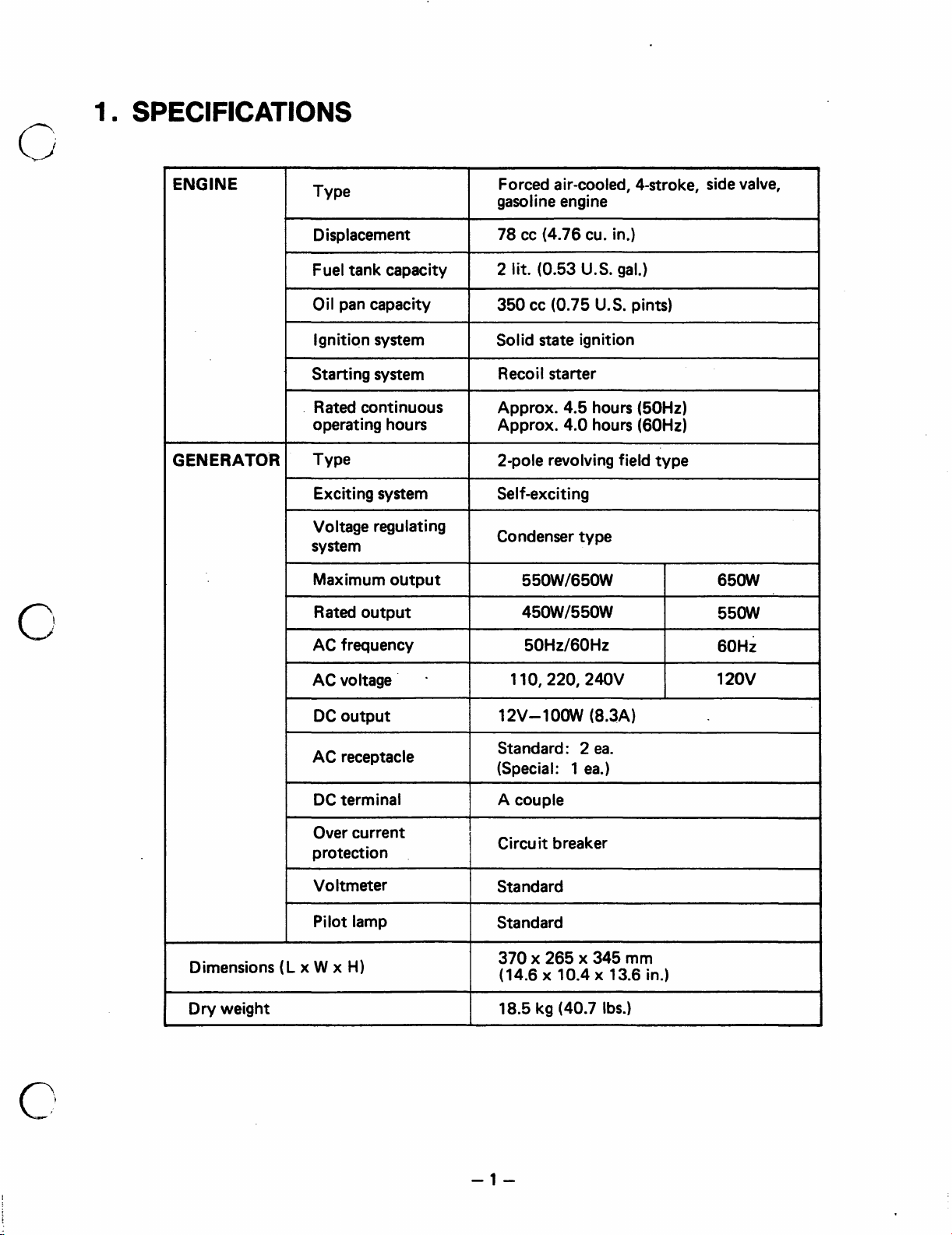
SPECIFICATIONS
c;
ENGINE
GENERATOR
Forced air-cooled, 4-stroke, side
gaso
I
i
ne engine
Displacement
Fuel tank capacity
Oil
pan capacity
Ignition system
Starting system
.
Rated continuous
operating hours
Type 2-pole revolving field type
Exciting system
Voltage regulating
system
Maximum output
Rated output
I
78
cc
(4.76 cu. in.)
I
2
lit.
(0.53
1
350
cc
(0.75 U.S. pints)
1
Solid
state
1
Recoil starter
Approx. 4.5 hours (50Hz)
Approx. 4.0 hours (60Hz)
I
Self-exciting
Condenser type
I
I
550W/650W
45OW/550W
U.S.
gal.)
ignition
I
I
valve,
65oW
55oW
Dimensions
AC frequency
AC voltage
DC output
AC receptacle
DC terminal
Over current
protection
Voltmeter
Pilot lamp
(L
x
W x H)
I
.
-
I
1
I
I
5OHz/6OHz
12V-1OOW (8.3A)
Standard: 2
(Special:
A
couple
Circuit breaker
Standard
Standard
370
x 265 x 345 mm
(14.6 x
1
10.4
ea.
ea.)
x 13.6 in.)
~
I
60Hz
-1-
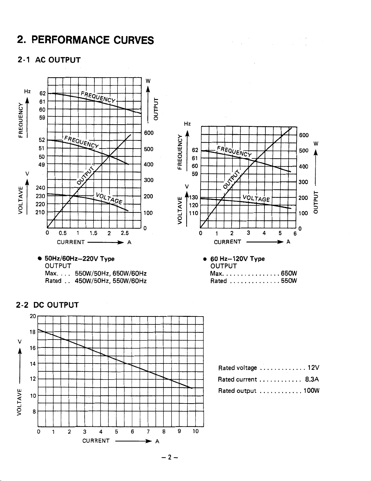
2.
PERFORMANCE CURVES
2-1
AC
OUTPUT
Hz
62
61
E
"I
3
K
LL
60
59
52
51 500
50
49 400
V
A
240
230
220
21
0
VIIIIIIIIIIIJo
0
0.5
1
1.5 2 2.5
CURRENT
-
A
W
I-
13
n
k
13
0
T
600
$
f
,"
300
200
k
100
t;
0
>
.i.-
Hz
162 61
60
59
120
110
600
w
500
400
1
300
I-
200
2
L
5
100
0
2-2
V
W
>
U
I-
50Hz/60Hz-220V
OUTPUT
Max.
...
Rated
DC
. .
OUTPUT
Type
550W/50Hz, 650W/60Hz
450W/50Hz, 550W/60Hz
0
60
Hz-1
OUTPUT
Max.
Rated
Rated voltage
Rated current
Rated output
20V
Type
..............
.............
.650W
.550W
.............
............
............
12V
8.3A
1OOW
-2-
3.
Exhaust Fan Cooling System for low body temperatures, low noise, longer engine life
and
reliable per-
formance.
0
Large
78
cc 4-Stroke Engine provides enough power for constant
Simple One-Touch Engine Control Switch with the engine and fuel on/off levers and choke
550W
(at
60
Hz)
rated output.
all
integrated
into one switch.
0
Easy and Reliable Starting with pointless ignition. This generator is also a brush-less type generator for
maintenance-free operation.
0
Simple Design
0
Compact and Lightweight with an easy one-hand carrying handle grip. This generator also offers a high
for
a clean appearance and easy maintenance.
power-to-weight ratio and economical operation.
0
Circuit Breaker Protection for safe operation. Replacement of fuses is not necessary in case
0
Unique Dual Output Design
so
that two separate
A.C.
and D.C. electrical appliances can be used at the
of
an overload.
same time.
0
Frequency Changeover Switch enables changing output frequency from
0
Optional Oil Warning System automatically stops the engine if the oil level drops below the lower limit.
50
Hz
to
60
Hz.
(Factory Option)
0
Resistor Spark Plug
0
Standard Tools are attached in the base plate for easy maintenance.
is
used as standard to prevent radio frequency noise.
0
AC Voltmeter is a standard equipment for monitoring output voltage.
-3-

4.
GENERAL DESCRIPTION
4-1
COMPONENT IDENTIFICATION
MUFFLER COVER
MUFFLER
OF
THE GENERATOR
HANDLE
.AIR
AIR
CLEANER
CLEANER
COVER
ENGINE
Fig.
4-
1
FUEL TANK
,GENERATOR
Fig.
-4-
4-2
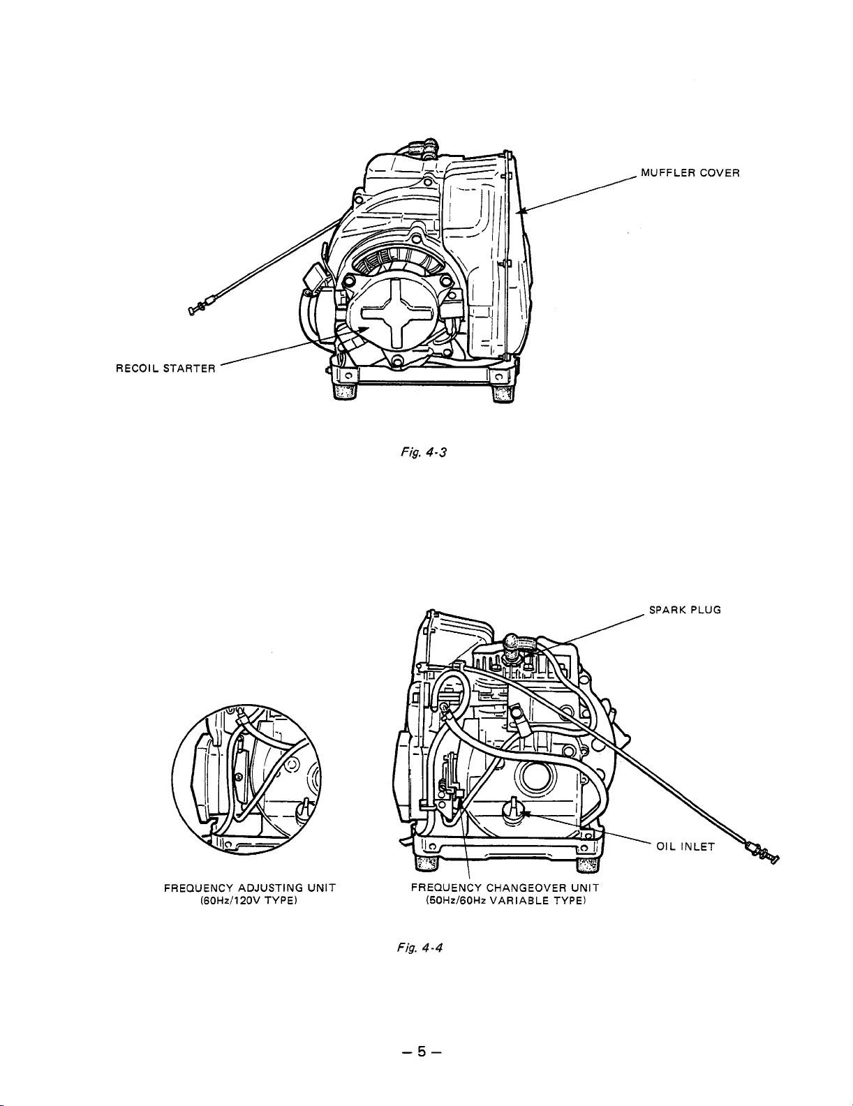
Fig.
MUFFLER COVER
4-3
FREQUENCY ADJUSTING UNIT
(60Hzi120V TYPE)
FREQUENCYCHANGEOVERUNIT
(50Hz/60Hz VARIABLE TYPE)
Fig.
4-4
SPARK PLUG
-5-

FRONT HOUSING
/
/
RECOIL
STARTER
\
Fig.
4-5
RUBBER
(FOR
AIR
I
CARBURETOR
PIPE
VENT)
BASE
PLATE
Fig.
-6-
4-6
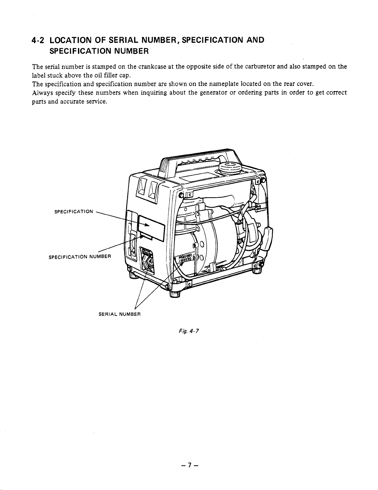
4-2
LOCATION OF
SERIAL
NUMBER, SPECIFICATION AND
SPECIFICATION NUMBER
The serial number is stamped on the crankcase at the opposite side of the carburetor and also stamped on the
label stuck above the oil filler cap.
The specification and specification number are shown on the nameplate located on the rear cover.
Always specify these numbers when inquiring about the generator or ordering parts in order to get correct
parts and accurate service.
SERIAL
NUMBER
Fig.
4-7
-7-

5.
CONSTRUCTION AND FUNCTION OF THE GENERATOR
5-1
CONSTRUCTION
FUEL TANK
SPARK PLUG
THROUGH BOLT CYLINDER
RECOIL STARTER
BALL BEARING
FIELD CORE STATOR
COIL
STATOR CORE COOLING FAN VIBRATION ISOLATOR
Fig.
5-
1
CRANKCASE
CRANKSHAFT
-a-

5-2
FUNCTION
OF
EACH COMPONENT
5-2-1
(1)
The stator consists of a laminated silicon steel sheet
core, a main coil and condenser coil which are
wound in the core slots.
AC and DC output are taken out from the main coil.
(DC output is taken out from the part of main coil
which is in the middle of the main coil.)
The condenser coil excites the stator field coil which
generates AC output in the main coil.
(2)
The condenser is mounted on the rear housing and is connected to the condenser coil which is wound in the
stator. The condenser coil magnetizes the rotor which increases the density of magnetic flux.
(3)
The rectifier is also mounted on the rear housing and it converts AC current output from the main coil
DC current. The
(4)
GENERATOR
STATOR
CONDENSER
RECTlFlCER
DC
ROTOR
C
Fig.
5-2
output from the diode of this rectifier is connected to the DC terminal.
‘IFIER
to
The rotor consists of a lamination silicon steel sheet
core and field coil which is wound over the core.
DC current in the filed coil magnetizes the steel
sheet core.
Two permanent magnets are provided at
from the poles for the primary exciting action.
A securely mounted fan is pressure-fitted on the end
of
the rotor shaft to cool the individual coils, iron
cores, rectifier, and other integral parts.
Cooling air from the fan is drawn in
lation vents in the rear housing, and is discharged
from the exhaust port in the front housing.
(5)
CONTROL PANEL
The panel on the front of the housing has a receptacle with
out with a male plug.
DC output is taken out from the red (positive,
and black (negative,
Control switch, circuit breaker, voltmeter and pilot
lamp are installed on the control panel.
a
ground terminal and AC output
-)
terminals.
from
90
degrees
the venti-
is
taken
+)
Fig.
5-3
I
-9-
Fig.
5-4

5-2-2
(1)
ENGINE
CYLINDER
and
CRANKCASE
The cylinder and the crankcase of the engine are of a one-piece aluminum die-cast design. The cast iron cylinder liner is molded inside the cylinder. Both the intake and exhaust ports are positioned at the lateral side
of the cylinder and these parts are formed by using a mold with die-cast cores. The crankcase has its joint
face located on the generator side.
(2)
MAIN BEARING COVER
The main bearing cover is aluminum die-cast and is mounted on the generator side. By removing the main
bearing cover, the interior
(3)
CRANKSHAFT
of
the engine can be inspected.
The crankshaft is constructed of forged carbon steel. The crankpin is induction-hardened and has a pressfitted crank gear located on the generator side of the engine.
(4)
CONNECTING
ROD
and
PISTON
The connecting rod is constructed of forged aluminum alloy with both the large and small ends utilized as
bearings. The oil scraper and large end cap are molded together. The aluminum alloy casting piston has two
compression rings and one oil ring.
(5)
CAMSHAFT
The camshaft is constructed of special cast iron and has intake and exhaust valve drive cams, each of which
An
engages with the cam gear.
exclusive aluminum alloy is used on each end of the camshaft in the place of
bearings.
(6)
VALVE ARRANGEMENT
The intake valve is installed at the oil port side and the exhaust valve at the generator side.
(7)
CYLINDER HEAD
The cylinder head is die-cast aluminum and has Ricardo type combustion chamber featuring greater volume
capacity for improved combustion efficiency. For easier spark plug maintenance, the cylinder head is positioned at an angle to allow greater access.
(8)
GOVERNOR
The centrifugal weight type governor ensures constant engine speed, regardless of load fluctuations (the
governor is mechanically linked to the governor drive gear).
(9)
EXHAUST FAN COOLING SYSTEM
Instead of blowing outside air on the engine, the Exhaust Fan Cooling System
(See
Fig.
5-5.)
of
this generator intakes the
cool air and forces the hot air outside from one outlet.
This keeps the body temperature lower for greater safety and extends service life.
(10)
LUBRICATION SYSTEM
The moving and sliding parts inside the engine are lubricated with the oil scraper fitted on the connecting
rod.
As
the crankshaft rotates, the connecting rod moves up and down and the oil scraper moves in conjunction with the connecting rod movements to scrape up oil in the crankcase and splash it over the surfaces of
the moving and sliding parts.
-
10-

(1
1)
IGNITION
A
flywheel/magneto igntion system is employed with the ignition timing set
The magneto is composed of the flywheel and ignition coil with the flywheel mounted on the rotor shaft.
The ignition coil is fitted to the front housing.
(12)
CARBURETOR
at
23'
before top dead center.
The horizontal draft type carburetor
celeration, low fuel consumption, and superior output. [For details concerning carburetor construction, see
the paragraph dealing with carburetor construction and disassembly/assembly (Page
(13)
AIR CLEANER
The air cleaner
is
a semi-wet type and contains a sponge element.
is
installed
so
that the engine will provide excellent starting, good ac-
59).]
Fig.
-
5-5
11
-
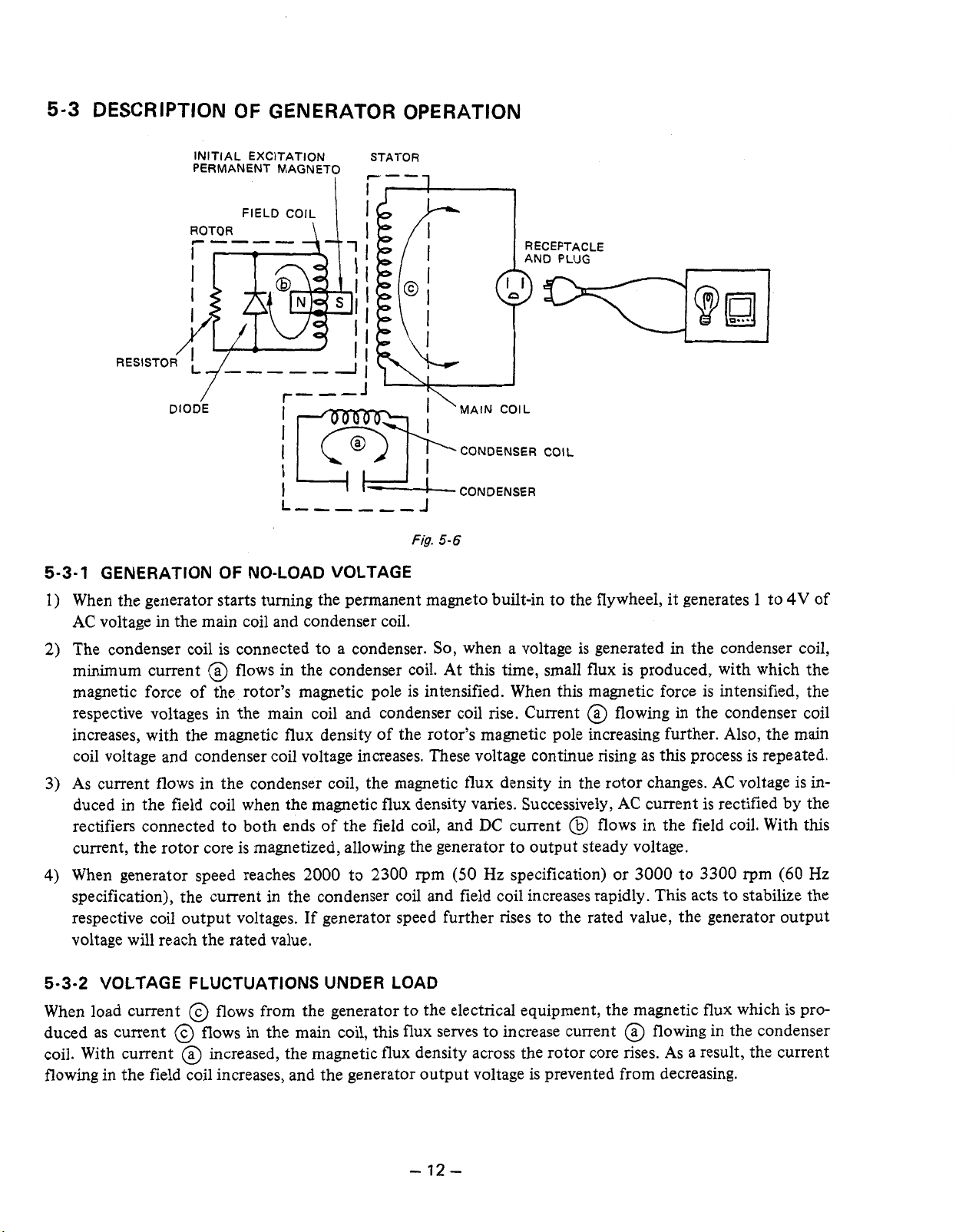
5-3
DESCRIPTION
OF
GENERATOR OPERATION
INITIAL EXCITATION
PERMANENT MAGNETO
ROTOR
\
I
/t.
I
Y-"!
I
DIODE
5-3-1 GENERATION OF NO-LOAD VOLTAGE
When the generator starts turning the permanent magneto built-in to the flywheel, it generates 1 to
AC
voltage in the main coil and condenser coil.
The condenser coil is connected to a condenser.
@
minimum current
magnetic force of the rotor's magnetic pole is intensified. When this magnetic force is intensified, the
respective voltages in the main coil and condenser coil rise. Current
increases, with the magnetic flux density of the rotor's magnetic pole increasing further. Also, the main
coil voltage and condenser coil voltage increases. These voltage continue rising as this process is repeated.
flows
I
A
I""""l
in
the condenser coil. At this time, small flux is produced, with which the
Fig.
'
MAIN COIL
CONDENSER
CONDENSER
5-6
So,
when a voltage
COIL
is
generated
@
flowing in the condenser coil
in
the condenser coil,
4V
of
As
current flows in the condenser coil, the magnetic flux density
duced in the field coil when the magnetic flux density varies. Successively,
DC
rectifiers connected to both ends of the field coil, and
current, the rotor core is magnetized, allowing the generator to output steady voltage.
When generator speed reaches
specification), the current in the condenser coil and field coil increases rapidly. This acts to stabilize the
respective coil output voltages. If generator speed further rises to the rated value, the generator output
voltage will reach the rated value.
5-3-2 VOLTAGE FLUCTUATIONS UNDER LOAD
When load current @ flows from the generator to the electrical equipment, the magnetic flux which
duced as current @ flows in the main coil, this flux serves to increase current
coil. With current
flowing in the field coil increases, and the generator output voltage is prevented from decreasing.
@
increased, the magnetic flux density across the rotor core rises.
2000
to
2300
rpm
-
(50
12-
current @ flows in the field coil. With this
Hz specification) or
in
the rotor changes.
AC
current is rectified by the
3000
@
flowing in the condenser
AC
voltage is in-
to
3300
rpm
As
a result, the current
(60
is
Hz
pro-

5-3-3
DC
OUTPUT
DC output is taken out from the main coil and is fed
to the diode at which time the output undergoes
full-wave rectification prior to being supplied to the
to
load connnected
fier works
to
allow the current to flow in
tion but does not allow the current to flow in
direction as shown in Fig.
Fig.
5-8
shows the DC output circuit of the genera-
the generator. The diode recti-
@
direc-
(@
5
-7.
tor.
in
DC voltage is generated
A
voltage in
is higher than that in
the main coil; when the
Cy
current
@
flows in the direction shown in the figure while no
current flows between
cut off by the diode
tioned, if the voltage in
current
@
flows in the direction
figure, with no current flowing between
This is because the diode
between
A
and
B.
C
and B because current is
D2.
Contrary to the aforemen-
C
is higher than that in
as
shown in the
A
Dl
cuts off the current
As
a result, voltage generated be-
and
A,
B.
tween the DC terminals has a waveform with two
peaks in one cycle, as in the case of the output wave-
form with two peaks in one cycle, as in the case of
the output waveform shown in Fig.
5-9.
MAIN
COIL
A
B
-0
-@
Fig.
Dl
5-7
+
BETWEEN A AND
C
BETWEEN
AND
B
B
Fig.
CURRENT
FLOWING FLOWING
BETWEEN
A
AND
5-9
OUTPUT WAVEFORM
@
B C
CURRENT
BETWEEN
Fig.
AND
5-8
@
B
-
13-

5-4
ELECTRONIC IGNITION SYSTEM
The electronic ignition system features a power transistor as the current control element. Therefore, the igni-
tion system is an electronic contact point-free type that operates with the power transistor impulses control-
TIC
ling the current. This system is also called
(transistor igniter circuit) and is virtually free of ignition failure which generally results from contamination of the contact points, a typical problem with contact type
ignition systems.
Because this ignition system has no contact points, it is not affected
As
nants.
The
wheel which is press-fitted on the rotor shaft
a result, this electronic ignition system ensures sure and positive ignition with reduced maintenance.
TIC
mechanism consists of a transistor-incorporated ignition coil and a permanent magneto built-in fly-
of
the generator.
I
//////
a
0
by
moisture, oil, dust, or other contami-
IGNITION COIL
"
IGNITION
TIMING
DETECTING
CIRCUIT
(1)
When the permanenet magneto built-in flywheel starts rotating, power is generated in the primary coil of
of the ignition coil and current flows to the resistor
a
a
I-
Fig.
5-
10
@
FLYWHEEL
COOLING FAN
.
>
a
*
SPARK PLUG
From the resistor, current flows to the power transistor. With this current, the power transistor turns on,
@
.
releasing current
(2)
As
the flywheel comes to the point of ignition, the ignition timing detecting circuit is activated while the
current
@
is flowing through the circuit.
This stage corresponds to the closing of contact points.
When the ignition timing detecting circuit is activated, the signal transmitter transistor actuates with cur-
@
rent d flowing. When current
As
cut quickly.
a result, high voltage is produced in the secondary coil and this voltage is applied simul-
taneously to the spark plug which ignites for ignition. This stage corresponds to the opening
starts flowing, current @ flowing through the power transistor is
of
points.
contact
-
14-
SAFETY
6.
1.
Use
extreme caution near gasoline. A constant danger
Do
not fill the fuel tank with gasoline while the engine is running.
PRECAUTIONS
of
explosion or fire exists.
Do
not smoke or use open flame near
the fuel tank. Be careful not to spill fuel when refueling. If spilt, wipe it and let it dry before starting the
engine.
2.
Do
not place inflammable materials near the generator.
Be careful not to put gasoline, matches, gunpowder, oil cloth, straw, trash and any other inflammables
near the generator.
0
Operate the generator at least 1 meter
3.
Do not operate the generator in a room, cave or tunnel. Always operate
(4
feet) away from a building or wall.
in
a
well-ventilated area.
Otherwise the engine may become overheated and also, the poisonous carbon monoxide contained in the
1
m
(4
exhaust gases will endanger human lives. Keep the generator at least
feet) away from structures or
facilities during use, and always operate it with the exhaust pipe directed toward the open-air or where
good ventilation is assured.
4.
Operate the generator on a level surface.
0
Do not operate the generator on a inclined surface.
0
Do not move or carry the generator while it is running.
5.
Do
not operate with wet hands or
in
the rain.
Severe electric shock may occur. If the generator is moistened by rain or snow, wipe it and fully dry it
before starting.
0
Do not pour water over the generator directly nor wash it with water.
If the generator is wet with water, the insulations will be adversely affected and may cause current leakage and electric shock.
6.
Do not connect the generator to the residential power source.
This could result in a malfunction of, or damge to the generator or appliance to which it is connected or
could even lead to fire.
7.
Do
not cover the generator with a carton,
a
box
or other cover while
it
is running.
-15-

7.
7-1
AC
OUTPUT
OF
APPLICATIONS
Generally, the rated power of
it. The electric power required for operating an electrical appliance is not always equal to the amount
work that can be done by it. Electrical appliances generally have a label showing their rated voltage, frequency, and power consumption (input power). The power consumption of an electrical appliance is the
power necessary for using it. When using a generator for operating an electrical appliance, however, the power factor and starting current must also be taken into consideration.
Determine the capacity of your generator from the power required for operating electrical appliances referring to the followsings:
(1
)
Incandescent lamps, hot plates, etc. with a power factor
Total power consumption must be equal to or less than the rated output of generator.
A
Example:
(2)
Fluorescent lamps, mercury lamps, etc. with a smaller power factor
Select a generator with a rated output equivalent to
Example:
NOTE:
generator with a rated output power
A
generator with a capacity of
A
generator with a rated output of
Wattage of the fluorescent lamp generally does not indicate the power consumption but indi-
cates the output of the lamp. Therefore, if the fluorescent lamp has no special indication as to
the power consumption of input power, efficiency should be taken into accounts as explained in
Item
5
on the following page.
an
electrical appliance often refers to the amount of work that can be done by
1
.O
of
500W can light five lOOW lamps.
1.2
1
OOW
to 2 times the power consumption
to
160W is necessary for lighting a 80W fluorescent lamp.
500W
can light three to five 40W fluorescent lamps.
of
the load.
of
(3)
Electric tools, etc. that are driven by a motor
1.2 to 3 times large power consumption of a motor-driven tool is required for starting. Select a generator
with a maximum output
Example:
(4)
Water pumps, compressors, etc. that are driven by a motor and are initially
3
to 5 times large power is necessary for starting. Select a generator with
load.
Example:
NOTE
NOTE
A
300W motor-driven drill requires a generator with a maximum output of
more.
A
water pump with a power consumption
of
put
I:
Motor-driven appliances mentioned in
capacities only when starting their motors. Once their motors are started, the appliances consume about
by the generator can be used for other electrical appliances.
2:
Motor-driven appliances mentioned in
er depending on the kind of motor and start-up load. If
mum generator capacity, select a generator with a larger capacity.
1200 to 2000W or more.
1.2
to 3 times large
1.2
to 2 times their rated power consumption
to
the load.
Items
Items
of
400W requires a generator with a maximum out-
3
and 4 required the aforementioned generator
3
and 4 vary in their required motor starting pow-
400
to 9OOW or
loaded
3
to
5
times large output of
so
that the excess power generated
it
is
difficult to determine the opti-
-
16
-
(5)
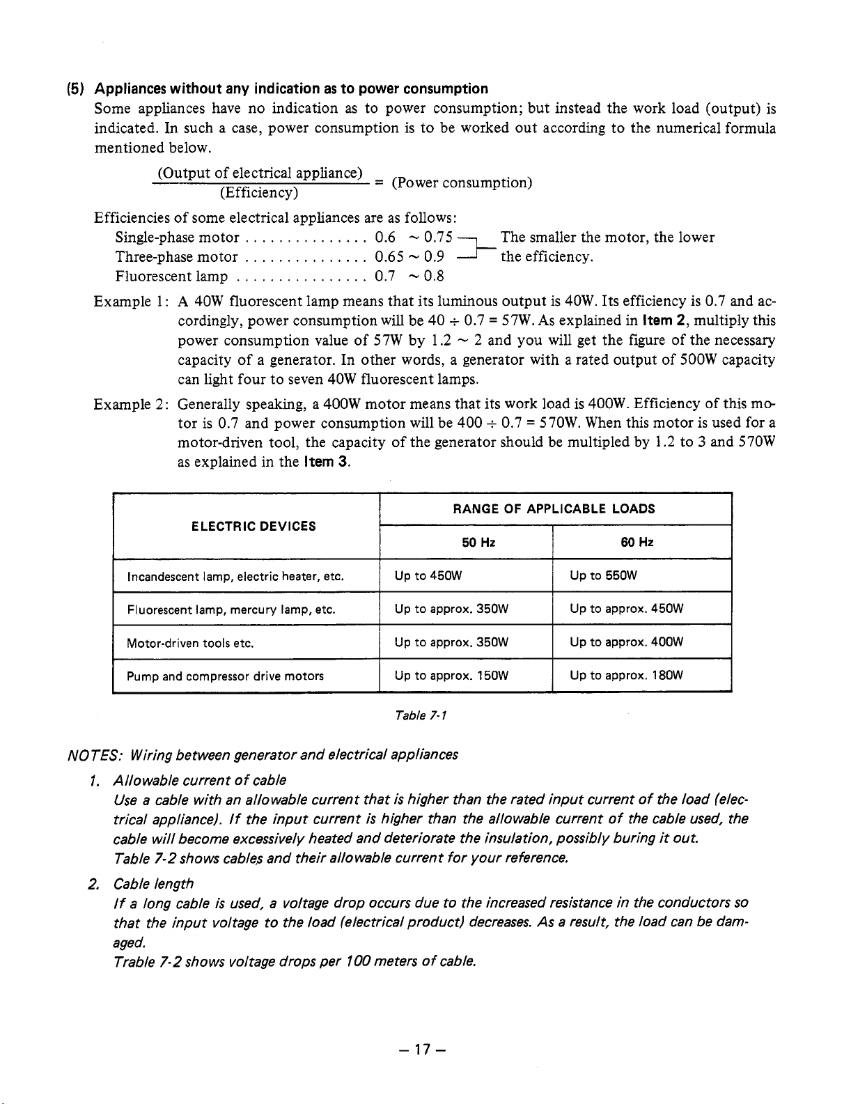
Appliances without any indication
Some appliances have no indication as to power consumption; but instead the work load (output) is
indicated. In such a case, power consumption is to be worked out according to the numerical formula
mentioned below.
as
to power consumption
(Output of electrical appliance)
(Efficiency)
Efficiencies of some electrical appliances are as follows:
Single-phase motor
Three-phase motor
Fluorescent lamp
Example
Example
r
1
:
A
40W fluorescent lamp means that its luminous output is 40W. Its efficiency is
cordingly, power consumption will be 40
power consumption value
capacity of a generator. In other words, a generator with a rated output of 500W capacity
can light four to seven 40W fluorescent lamps.
2:
Generally speaking, a 400W motor means that its work load is 400W. Efficiency of this me
tor is 0.7 and power consumption will be 400
motor-driven tool, the capacity of the generator should be multipled by
as explained in the
ELECTRIC DEVICES
Incandescent lamp, electric heater, etc.
...............
...............
................
Item
~ ~
=
0.65
0.7
of
57W by 1.2
3.
(Power consumption)
0.6
-
-
0.9
Oa7'
-
0.8
+
The smaller the motor, the lower
the efficiency.
0.7 = 57W.
-
2
and you will get the figure of the necessary
+
RANGE
50
Hz
As
explained in
0.7 = 570W. When this motor is used for a
OF
APPLICABLE LOADS
Up to 550W Up to 450W
60
Item
1.2
Hz
2,
multiply this
to 3 and 570W
0.7
and ac-
Fluorescent lamp, mercury lamp, etc.
Motor-driven tools etc.
Pump and compressor drive motors
NOTES: Wiring between generator and electrical appliances
Allowable current of cable
1.
Use a cable with an allowable current that
If
trical appliance).
cable will become excessively heated and deteriorate the insulation, possibly burins
7-2
Table
Cable length
2,
If a long cable
that the input voltage to the load (electrical product) decreases.
aged.
Trable
shows cables and their allowable current
7-2
shows voltage drops per
the input current
is
used, a voltage drop occurs due to the increased resistance in the conductors
100
Up to approx. 150W
Table
7-
1
is
higher than the rated input current
is
higher than the allowable current
for
meters
of
cable.
your reference.
As
a result, the load can be darn-
Up to approx. 450W Up to approx. 350W
Up to approx. 400W Up to approx. 350W
Up to approx. 180W
of
the load (elec-
of
the cable used, the
it
out.
so
-
17
-

Table
7-2
Voltage decrease indicates as V
R
means resistance
I
means electric current through the wire
2
means the length of the wire (m).
(5211
00
=
-
xRxIx!?
100
m)
on the above table.
(A).
The length of the wire indicates round length, it means twice the length from generator to electrical
tools.
7-2
DC
OUTPUT
When the generator is employed to recharge batteries, care must be exercised about the specific gravity
electrolyte in each battery case.
7-2-1
The specific gravity changes with temperature; therefore, it is converted to another, corresponding to
MEASURING THE SPECIFIC GRAVITY
S20
=
St
+
0.0007
(t
-
20)
OF
ELECTROLYTE:
20°C.
where
S20
=
7-2-2
Specific gravity corresponding to
St
=
Measured value
t
=
Temperature at time
REMAINING CAPACITY ESTIMATED WITH REFERENCE TO THE SPECIFIC GRAVITY
ELECTROLYTE:
of
measurement
20°C
OF
of
SPECIFIC
GRAVITY
(2OOC)
1.260
1.240
1.220
1.200
1.180
1.160
1.140
REMAINING BATTERY
(%I
100
87
75
62
50
37
25
Table
7-3
-
18
-
REMARKS
Good charged condition
Charging
Immediate charging
is
necessary.
is
necessary.
7-2-3
BATTERY CAPACITY
The battery capacity is expressed in units of ampere-hour
of
providing one ampere
7-2-4
If
SIMULTANEOUS USE
you
use the
AC/DC
current for one hour.
OF
THE AC/DC OUTPUT
output simultaneously in this generator, be careful not
sumption.
50
60
NOTE:
Hz
Hz
Max.
output
of
DC
below
below
is
lOOW
250W
350W
(12V
x
8.3A).
(AH).
One
AH
stands for the capacity capable of
to
exceed the total power con-
-
19-
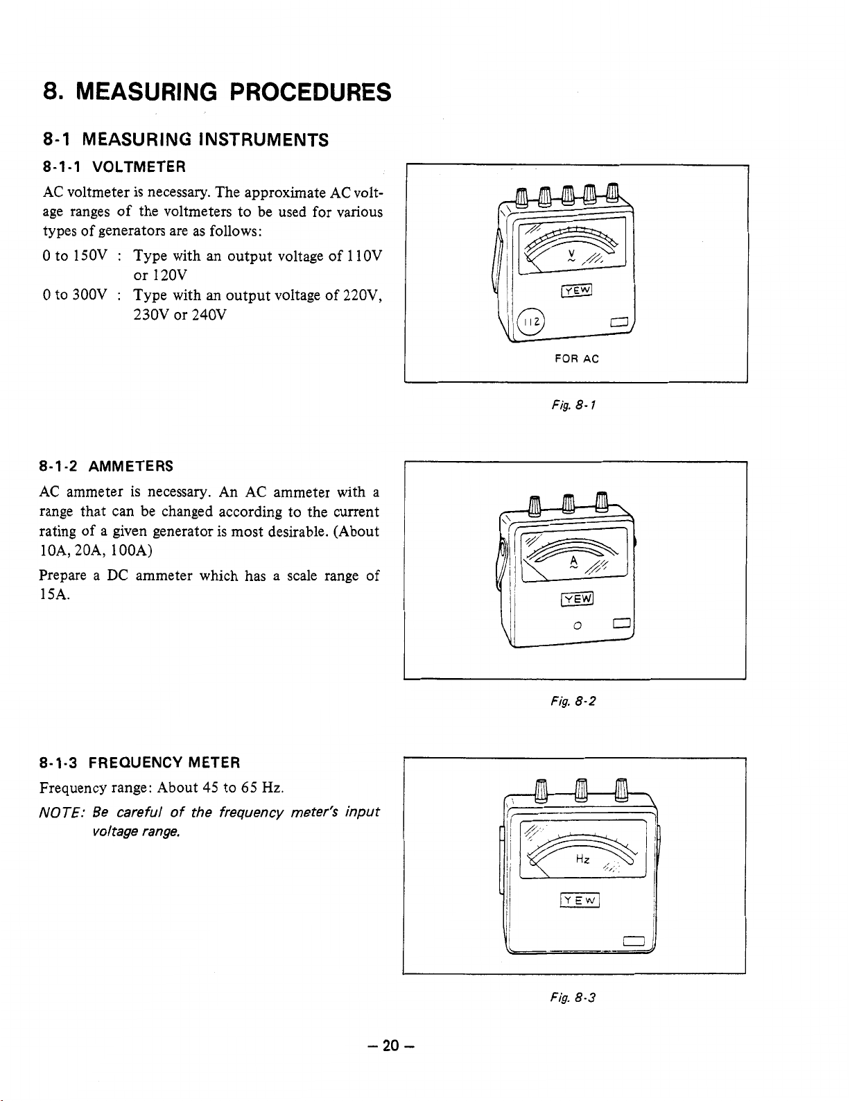
8.
MEASURING PROCEDURES
8-1
MEASURING INSTRUMENTS
8-1-1
AC voltmeter is necessary. The approximate AC voltage ranges of the voltmeters to be used for various
types of generators are as follows:
0
0
8-1
AC ammeter is necessary. An AC ammeter with a
range that can be changed according to the current
rating of a given generator is most desirable. (About
1 OA, 20A,
VOLTMETER
to 150V : Type with an output voltage
or 12OV
to 300V : Type with an output voltage
230V
or 240V
-2
AMMETERS
1
OOA)
of
of
1
1OV
220V,
Fig.
8-
I
Prepare a DC ammeter which has a scale range
15A.
8-1-3
Frequency range: About 45 to
NOTE:
FREQUENCY METER
Be careful
voltage range.
of
the frequency meter's input
65
Hz.
of
9
Fig.
8-2
-
20
-
Fig.
8-3
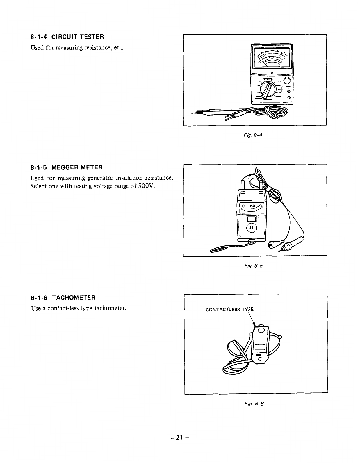
8-1-4 CIRCUIT TESTER
Used for measuring resistance, etc.
8-1-5 MEGGER METER
Used for measuring generator insulation resistance.
Select one with testing voltage range of
500V.
I
I
Fig.
Fig.
I'
8-4
8-5
,,
8-1
-6
TACHOMETER
Use a contact-less type tachometer.
-
21
CONTACTLESS TYPE
\
I
Fig.
8-6
I
-
 Loading...