

Page 1

2002 LEGACY SERVICE MANUAL
NEW CAR INFORMATION SECTION
QUICK REFERENCE INDEX
Specifications SPC
FOREWORD
This manual has been prepared to provide information
for the construction, operation and other technical details of SUBARU vehicles.
Read this manual thoroughly and make the most of it
to give better service to your customers and improve
your knowledge of vehicle maintenance.
Fuel Injection (Fuel System) FU
Fuel Injection (Fuel System)
Emission Control
(Aux. Emission Control Devices)
Emission Control
(Aux. Emission Control Devices)EC (w/o OBD)
Intake (Induction) IN
Mechanical ME
Exhaust EX
Exhaust
Cooling CO
(w/o OBD)
(w/o OBD)
FU
EC
EX
All information, illustration and specifications contained in this manual are based on the latest product
information available at the time of publication approval.
FUJI HEAVY INDUSTRIES LTD.
Lubrication LU
Speed Control System SP
Ignition IG
Ignition
Starting/Charging SC
Fuel Injection (Fuel System)
Emission Control
(Aux. Emission Control Devices)
Intake (Induction)
(w/o OBD)
IG
FU
(H6)
EC
(H6)
IN
(H6)
W2290GE
Page 2

FOREWORD
QUICK REFERENCE INDEX
Mechanical
Exhaust
Cooling
Lubrication
Speed Control System
Ignition
Starting/Charging
Control System CS
Automatic Transmission AT
ME
(H6)
EX
(H6)
CO
(H6)
LU
(H6)
SP
(H6)
IG
(H6)
SC
(H6)
Manual Transmission and Differential MT
Clutch CL
Front Suspension FS
Rear Suspension RS
Differentials DI
Drive Shaft System DS
ABS ABS
VDC VDC
Brakes BR
Page 3

FOREWORD
Parking Brake PB
QUICK REFERENCE INDEX
Power Assisted System
(Power Steering)
HVAC System
(Heater, Ventilator and A/C)
Airbag System AB
Seat Belt System SB
Wiper and Washer Systems WW
Glass/Windows/Mirrors GW
Body Structure BS
Instrumentation/Driver Info IDI
Seats SE
PS
AC
Security and Locks SL
Sunroof/T-top/Convertible Top SR
Exterior Body Panels EB
Cruise Control System CC
Exterior/Interior Trim EI
Page 4

FOREWORD
All right reserved. This book may not be reproduced or
copied, in whole or in part, without the written permission of FUJI HEAVY INDUSTRIES LTD., TOKYO JAPA N
SUBARU, and are trademarks of FUJI
HEAVY INDUSTRIES LTD.
Copyright 2001 FUJI HEAVY INDUSTRIES LTD.
Page 5

SPECIFICATIONS
1. Legacy ............................................................................................................. 2
2. OUTBACK ....................................................................................................... 10
SPC
Page
Page 6

LEGACY
Specifications
1. Legacy
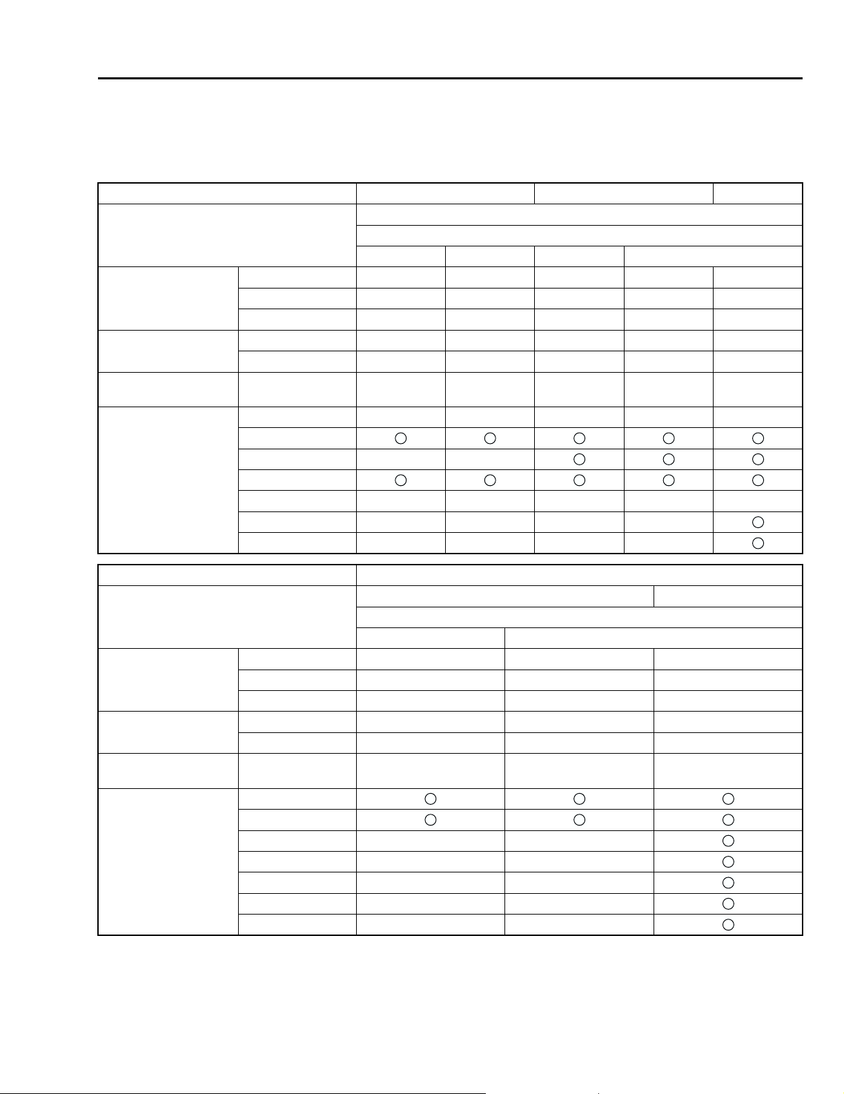
A: DIMENSIONS
Model Sedan Wagon
AWD
Overall length mm (in) 4,605 (181.3) 4,680 (184.3)
Overall width mm (in) 1,695 (66.7) 1,695 (66.7)
Overall height (at CW) mm (in) 1,415 (55.7) 1,515 (59.6)
Compartment Length mm (in) 1,965 (77.4) 1,925 (75.8)
Width mm (in) 1,440 (56.7), 1,420 (55.9)*1 1,440 (56.7), 1,420 (55.9)*1
Height mm (in) 1,155 (45.5) 1,190 (46.9), 1,175 (46.3)*2
Wheelbase mm (in) 2,650 (104.3) 2,650 (104.3)
Tread Front mm (in) 1,460 (57.5) 1,460 (57.5)
Rear mm (in) 1,460 (57.5) 1,455 (57.3)
Minimum road
clearance
Without catalytic
converter
With catalytic
converter
Australia mm (in) 155 (6.1) 155 (6.1)
mm (in) 160 (6.3) 165 (6.5)
mm (in) 155 (6.1) 155 (6.1)
*1: With leather seat
*2: With sunroof
B: ENGINE
Model Sedan/Wagon
AWD
2.0 L 2.5 L
Engine type Horizontally opposed, liquid cooled, 4-cylinder, 4-stroke gasoline engine
Valve arrangement Overhead camshaft type
Bore × Stroke mm (in) 92 × 75 (3.62 × 2.95) 99.5 × 79.0 (3.917 × 3.110)
Displacement cm
Compression ratio 10.0
Firing order 1 — 3 — 2 — 4
Idle speed at Park/Neutral
position
Maximum output kW (HP)/rpm 92 (123)/5,600 115 (154)/5,600
Maximum torque N·m (kgf-m, ft-lb)/rpm 184 (18.8, 136.0)/3,600 223 (22.7, 164.2)/3,600
3
(cu in) 1,994 (121.67) 2,457(149.9)
rpm 700±100
SPC-2
Page 7

LEGACY
C: ELECTRICAL
Model Sedan/Wagon
AWD
2.0 L 2.5 L
Ignition timing at idling speed BTDC/rpm 10°±10°/700
Spark plug Type and manufacturer Without OBD NGK: BKR6E (without catalyst)
CHAMPION: RC10YC4 (with catalyst)
NGK: BKR5E-11 (with catalyst)
With OBD RC10YC4 .......... CHAMPION
Alternate RC8YC4 .......... CHAMPION
BKR6E-11 .......... NGK
K20PR-U11 .......... NIPPONDENSO
Generator 12V — 90A
Battery Type and capacity (5HR) For Europe and
South America
Others 12V — 27AH (34B19L)
MT: 12V — 48AH (55D23L)
AT: 12V — 52AH (65D23L)
MT: 12V — 48AH (55D23L)
AT: 12V — 52AH (75D23L)
D: TRANSMISSION
Specifications
Model Sedan/Wagon
AWD
2.0 L 2.5 L
Transmission type 5MT 4AT 5MT 4AT
Clutch type DSPD TCC DSPD TCC
Gear ratio 1st 3.454 2.785 3.454 2.785
2nd 2.062 1.545 2.062 1.545
3rd 1.448 1.000 1.448 1.000
4th 1.088 0.694 1.088 0.694
5th 0.825 — 0.825*1, 0.780*2 —
Reverse 3.333 2.272 3.333 2.272
Auxiliary transmission gear ratio High 1.000 — 1.000 —
Low 1.447 — 1.196 —
Reduction gear
(Front drive)
Reduction gear
(Rear drive)
1st reduction Type of gear — Helical — Helical
Gear ratio — 1.000 — 1.000
Final reduction Type of gear Hypoid Hypoid Hypoid Hypoid
Gear ratio 3.900 4.111 3.700*1, 4.111*2 4.111
Tr a n sf e r
reduction
Final reduction Type of gear Hypoid Hypoid Hypoid Hypoid
Type of gear Helical — Helical —
Gear ratio 1.000 — 1.000 —
Gear ratio 3.900 4.111 3.700*1, 4.111*2 4.111
5MT: 5-forward speeds with synchromesh and 1-reverse
4AT: Electronically controlled fully-automatic, 4-forward speeds and 1-reverse
DSPD: Dry Single Plate Diaphragm
TCC: Torque Converter Clutch
*1: Except Australia spec. vehicles
*2: Australia spec. vehicles
SPC-3
Page 8

Specifications
E: STEERING
LEGACY
Model Models with
185/70R14 tires
Ty pe Rack and Pinion
Turns, lock to lock 3.1
Minimum turning circle m (ft) Curb to curb: 10.8±1.0 (35.4±3.3)
Wall to wall: 11.5±1.0 (37.7±3.3)
Models with
195/60R15 tires
Models with
205/50R16 tires
F: SUSPENSION
Model Conventional suspension
Front Macpherson strut type, Independent, Coil spring
Rear Multi-link type, Independent, Coil spring
G: BRAKE
Service brake system Dual circuit hydraulic with vacuum suspended power unit
Front Ventilated disc brake
Rear Disc brake
Parking brake Mechanical on rear brakes
H: TIRE
Rim size 14 × 5½JJ 15 × 6JJ 16 × 6½JJ
Tire size 185/70R14 195/60R15 205/50R16
Type Steel belted radial, Tubeless
I: CAPACITY
Model Sedan/Wagon
AWD
2.0 L 2.5 L
5MT4AT5MT4AT
Fuel tank (US gal, Imp gal) 64 (16.9, 14.1)
Engine oil Total capacity (US qt, Imp qt) 4.0 (4.2, 3.5)
Engine oil
amount for refill
Transmission gear oil (US qt, Imp qt) 3.5 (3.7, 3.1) — 3.5 (3.7, 3.1) —
Automatic transmission fluid (US qt, Imp qt) — 8.4 – 8.7
AT differential gear oil (US qt, Imp qt) — 1.1 – 1.3
AWD rear differential gear oil (US qt, Imp qt) 0.8 (0.8, 0.6)
Power steering fluid (US qt, Imp qt) 0.7 (0.7, 0.6)
Engine coolant (US qt, Imp qt) 7.0 (7.4, 6.2) 6.9 (7.3, 6.1) 6.8 (7.2, 6.0) 6.7 (7.1, 5.9)
(US qt, Imp qt) Approx. 4.0 (4.2, 3.5)
— 9.3 – 9.6
(8.9 – 9.2,
7.4 – 7.7)
— 1.1 – 1.3
(1.2 – 1.4,
1.0 – 1.1)
(9.8 – 10.1,
8.2 – 8.4)
(1.2 – 1.4,
1.0 – 1.1)
SPC-4
Page 9
LEGACY
Specifications
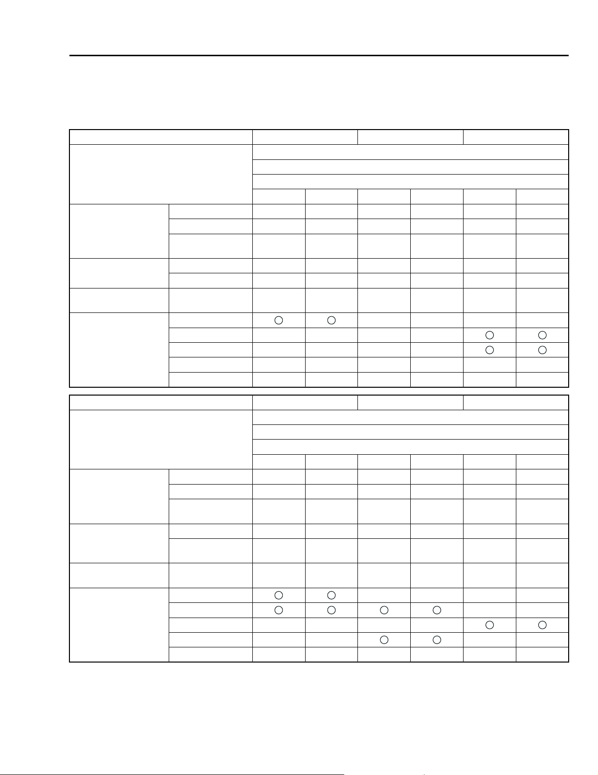
J: WEIGHT
1. SEDAN
! LHD Vehicle
Option code *1 EC K4 KO, KS
Model 2.0 L
4WD
GL
5MT 4AT 5MT 4AT 5MT 4AT
Curb weight (C.W.) Front kg (lb) 785 (1,730) 810 (1,785) 775 (1,710) 800 (1,765) 790 (1,740) 815 (1,795)
Rear kg (lb) 605 (1,335) 605 (1,335) 610 (1,345) 610 (1,345) 610 (1,345) 610 (1,345)
Total kg (lb) 1,390
(3,065)
Maximum permissible
axle weight (M.P.A.W.)
Maximum permissible
weight (M.P.W.)
Option Side airbag ————
Front kg (lb) 970 (2,140) 970 (2,140) 970 (2,140) 970 (2,140) 970 (2,140) 970 (2,140)
Rear kg (lb) 975 (2,150) 975 (2,150) 975 (2,150) 975 (2,150) 975 (2,150) 975 (2,150)
Total kg (lb) 1,870
(4,125)
Air conditioner ————
Audio ————
Cruise control ——————
Cold weather pack ——————
1,415
(3,120)
1,870
(4,125)
1,385
(3,055)
1,870
(4,125)
1,410
(3,110)
1,870
(4,125)
1,400
(3,085)
1,870
(4,125)
1,425
(3,140)
1,870
(4,125)
Option code *1 EC K4 KO, KS
Model 2.5 L
4WD
GX
5MT 4AT 5MT 4AT 5MT 4AT
Curb weight (C.W.) Front kg (lb) 805 (1,775) 830 (1,830) 795 (1,755) 820 (1,810) 785 (1,730) 810 (1,785)
Rear kg (lb) 605 (1,335) 610 (1,345) 610 (1,345) 615 (1,355) 610 (1,345) 615 (1,355)
Total kg (lb) 1,410
(3,110)
Maximum permissible
axle weight (M.P.A.W.)
Maximum permissible
weight (M.P.W.)
Option Side airbag ————
*1: For option code, refer to ID section. <Ref. to ID-5, MODEL NUMBER PLATE, IDENTIFICATION, Identification.>
Front kg (lb) 985 (2,170) 985 (2,170) 985 (2,170) 985 (2,170) 985 (2,170) 985 (2,170)
Rear kg (lb) 1,000
(2,205)
Total kg (lb) 1,910
(4,210)
Air conditioner ——
Audio ————
Cruise control —— ——
Cold weather pack ——————
1,440
(3,175)
1,000
(2,205)
1,910
(4,210)
1,405
(3,110)
1,000
(2,205)
1,910
(4,210)
1,435
(3,165)
1,000
(2,205)
1,910
(4,210)
1,395
(3,075)
1,000
(2,205)
1,910
(4,210)
1,425
(3,140)
1,000
(2,205)
1,910
(4,210)
SPC-5
Page 10
LEGACY
Specifications
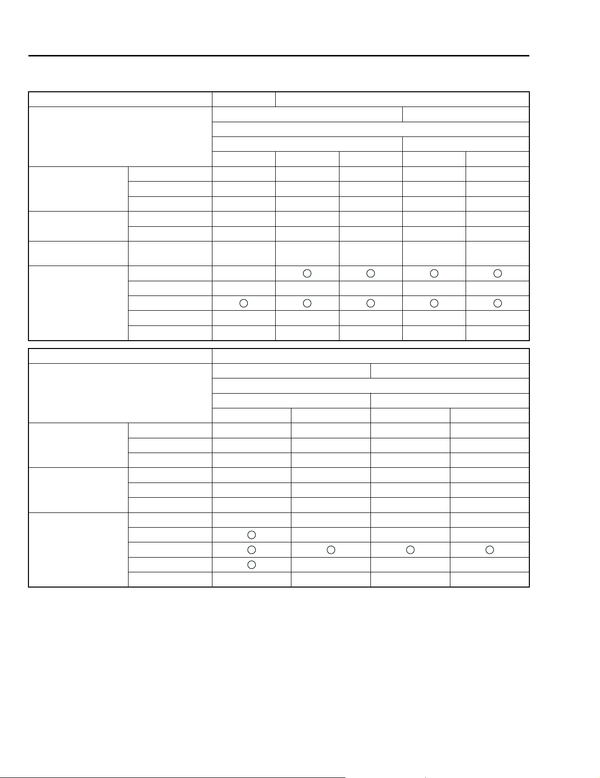
! RHD Vehicle
Option code *1 K1 EK
Model 2.0 L 2.5 L
4WD
GL GX
4AT 5MT 4AT 5MT 4AT
Curb weight (C.W.) Front kg (lb) 800 (1,765) 785 (1,730) 810 (1,785) 795 (1,755) 820 (1,810)
Rear kg (lb) 605 (1,335) 605 (1,335) 605 (1,335) 605 (1,335) 610 (1,345)
Total kg (lb) 1,405 (3,100) 1,390 (3,065) 1,415 (3,120) 1,400 (3,085) 1,430 (3,155)
Maximum permissible
axle weight (M.P.A.W.)
Maximum permissible
weight (M.P.W.)
Option Side airbag —
Front kg (lb) 970 (2,140) 970 (2,140) 970 (2,140) 985 (2,170) 985 (2,170)
Rear kg (lb) 975 (2,150) 975 (2,150) 975 (2,150) 1,000 (2,205) 1,000 (2,205)
Total kg (lb) 1,870 (4,125) 1,870 (4,125) 1,870 (4,125) 1,910 (4,210) 1,910 (4,210)
Air conditioner —————
Audio
Cruise control —————
Cold weather pack —————
Option code *1 KA
Model 2.0 L 2.5 L
4WD
GL (GX) GX (RX)
5MT4AT5MT4AT
Unladen mass (U.M.) Front kg (lb) 780 (1,720) 775 (1,710) 775 (1,710) 785 (1,730)
Rear kg (lb) 585 (1,290) 585 (1,290) 595 (1,310) 595 (1,310)
Total kg (lb) 1,365 (3,010) 1,360 (3,000) 1,370 (3,020) 1,380 (3,045)
Gross vehicle mass
(G.V.M.)
Option Side airbag ————
*1: For option code, refer to ID section. <Ref. to ID-5, MODEL NUMBER PLATE, IDENTIFICATION, Identification.>
Front kg (lb) 930 (2,050) 930 (2,050) 940 (2,075) 940 (2,075)
Rear kg (lb) 970 (2,140) 970 (2,140) 980 (2,160) 980 (2,160)
Total kg (lb) 1,900 (4,190) 1,900 (4,190) 1,920 (4,235) 1,920 (4,235)
Air conditioner ———
Audio
Cruise control ———
Cold weather pack ————
SPC-6
Page 11
LEGACY
Specifications
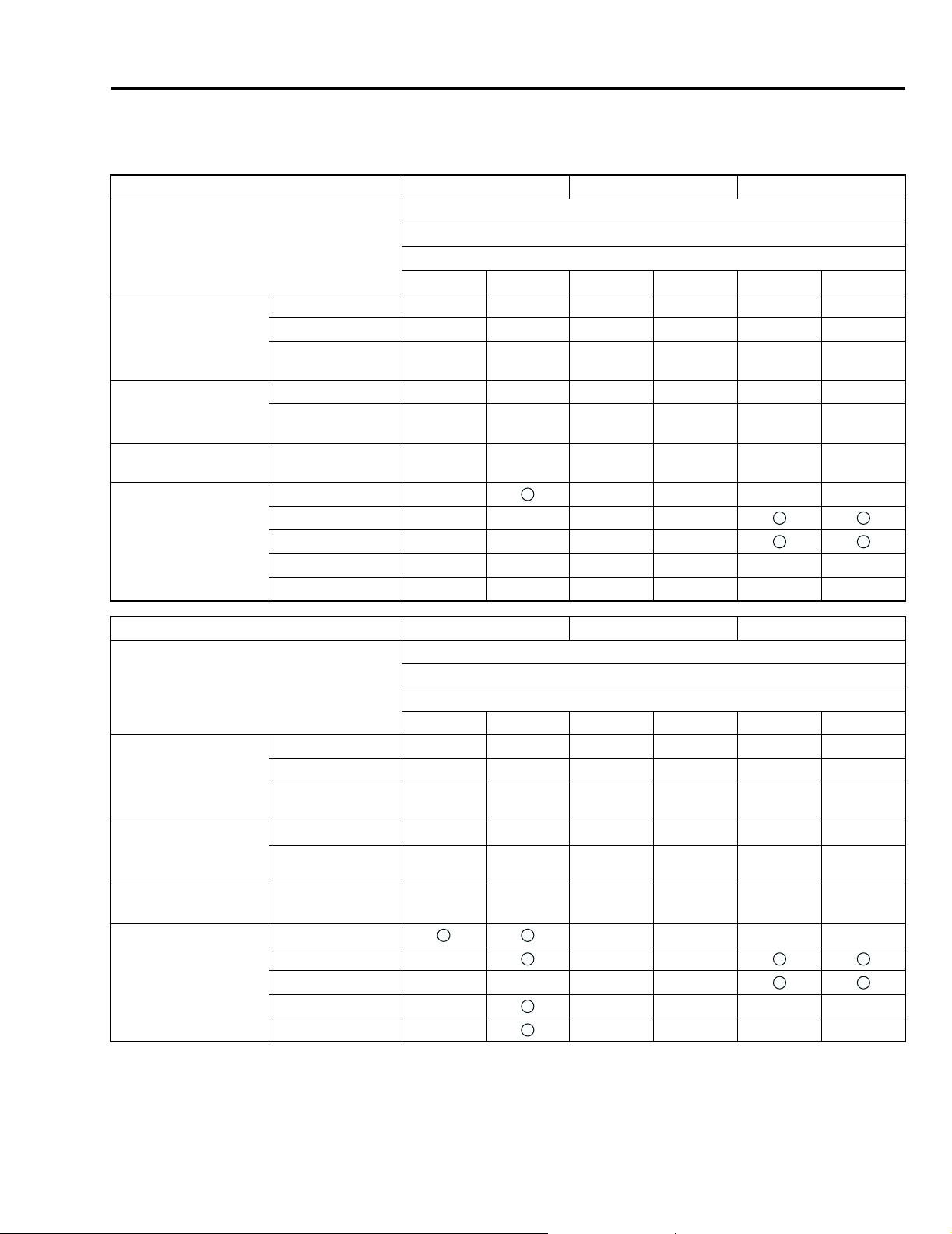
2. WAGON
! LHD Vehicle
Option code *1 EC K4 KO, KS
Model 2.0 L
4WD
GL
5MT 4AT 5MT 4AT 5MT 4AT
Curb weight (C.W.) Front kg (lb) 780 (1,720) 800 (1,765) 775 (1,710) 790 (1,740) 790 (1,740) 805 (1,775)
Rear kg (lb) 650 (1,435) 650 (1,435) 655 (1,445) 655 (1,445) 655 (1,445) 655 (1,445)
Total kg (lb) 1,430
Maximum permissible
axle weight (M.P.A.W.)
Maximum permissible
weight (M.P.W.)
Option Side airbag —————
Front kg (lb) 960 (2,115) 960 (2,115) 960 (2,115) 960 (2,115) 960 (2,115) 960 (2,115)
Rear kg (lb) 1,030
Total kg (lb) 1,920
Air conditioner ————
Audio ————
Cruise control ——————
Cold weather pack ——————
(3,155)
(2,270)
(4,235)
1,450
(3,195)
1,030
(2,270)
1,920
(4,235)
1,430
(3,155)
1,030
(2,270)
1,920
(4,235)
1,445
(3,185)
1,030
(2,270)
1,920
(4,235)
1,445
(3,185)
1,030
(2,270)
1,920
(4,235)
1,460
(3,220)
1,030
(2,270)
1,920
(4,235)
Option code *1 EC K4 KO, KS
Model 2.5 L
4WD
GX
5MT 4AT 5MT 4AT 5MT 4AT
Curb weight (C.W.) Front kg (lb) 790 (1,740) 820 (1,810) 775 (1,710) 790 (1,740) 790 (1,740) 805 (1,775)
Rear kg (lb) 655 (1,445) 655 (1,445) 655 (1,445) 655 (1,445) 655 (1,445) 655 (1,445)
Total kg (lb) 1,445
Maximum permissible
axle weight (M.P.A.W.)
Maximum permissible
weight (M.P.W.)
Option Side airbag ————
*1: For option code, refer to ID section. <Ref. to ID-5, MODEL NUMBER PLATE, IDENTIFICATION, Identification.>
Front kg (lb) 995 (2,195) 995 (2,195) 960 (2,115) 960 (2,115) 960 (2,115) 960 (2,115)
Rear kg (lb) 1,050
Total kg (lb) 1,980
Air conditioner ———
Audio ————
Cruise control —————
Cold weather pack —————
(3,185)
(2,315)
(4,365)
1,475
(3,250)
1,050
(2,315)
1,980
(4,365)
1,430
(3,155)
1,030
(2,270)
1,920
(4,235)
1,445
(3,185)
1,030
(2,270)
1,920
(4,235)
1,445
(3,185)
1,030
(2,270)
1,920
(4,235)
1,460
(3,220)
1,030
(2,270)
1,920
(4,235)
SPC-7
Page 12
LEGACY
Specifications
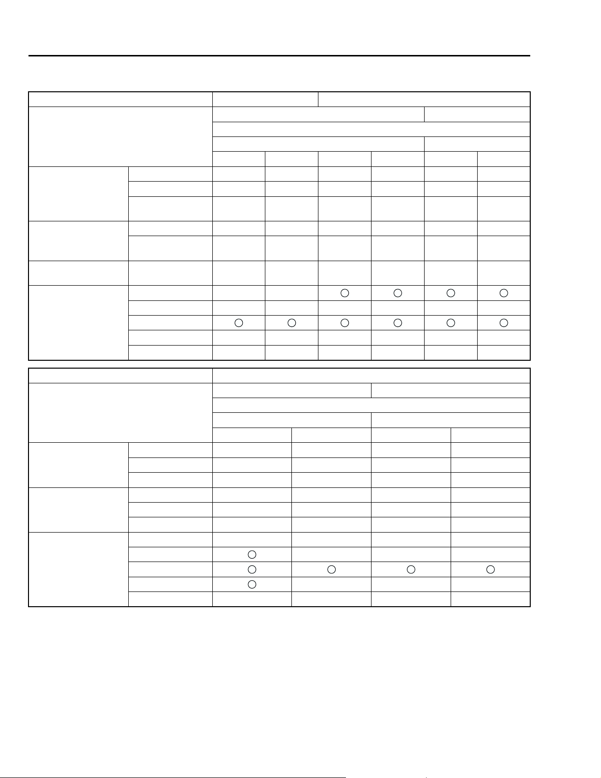
! RHD Vehicle
Option code *1 K1 EK
Model 2.0 L 2.5 L
4WD
GL GX
5MT 4AT 5MT 4AT 5MT 4AT
Curb weight (C.W.) Front kg (lb) 775 (1,710) 790 (1,740) 785 (1,731) 800 (1,765) 790 (1,740) 805 (1,775)
Rear kg (lb) 655 (1,445) 655 (1,445) 650 (1,435) 650 (1,435) 655 (1,445) 655 (1,445)
Total kg (lb) 1,430
(3,155)
Maximum permissible
axle weight (M.P.A.W.)
Maximum permissible
weight (M.P.W.)
Option Side airbag ——
Front kg (lb) 960 (2,115) 960 (2,115) 960 (2,115) 960 (2,115) 995 (2,195) 995 (2,195)
Rear kg (lb) 1,030
(2,270)
Total kg (lb) 1,920
(4,235)
Air conditioner ——————
Audio
Cruise control ——————
Cold weather pack ——————
1,445
(3,185)
1,030
(2,270)
1,920
(4,235)
1,435
(3,165)
1,030
(2,270)
1,920
(4,235)
1,450
(3,195)
1,030
(2,270)
1,920
(4,235)
1,445
(3,185)
1,050
(2,315)
1,980
(4,365)
1,460
(3,220)
1,050
(2,315)
1,980
(4,365)
Option code *1 KA
Model 2.0 L 2.5 L
4WD
GL (GX) GX (RX)
5MT4AT5MT4AT
Unladen mass (U.M.) Front kg (lb) 775 (1,710) 775 (1,710) 765 (1,685) 780 (1,720)
Rear kg (lb) 635 (1,400) 635 (1,400) 645 (1,420) 645 (1,420)
Total kg (lb) 1,410 (3,110) 1,410 (3,110) 1,410 (3,110) 1,425 (3,140)
Gross vehicle mass
(G.V.M.)
Option Side airbag ————
*1: For option code, refer to ID section. <Ref. to ID-5, MODEL NUMBER PLATE, IDENTIFICATION, Identification.>
Front kg (lb) 930 (2,050) 930 (2,050) 950 (2,095) 950 (2,095)
Rear kg (lb) 1,010 (2,225) 1,010 (2,225) 1,040 (2,295) 1,040 (2,295)
Total kg (lb) 1,940 (4,280) 1,940 (4,280) 1,990 (4,390) 1,990 (4,390)
Air conditioner ———
Audio
Cruise control ———
Cold weather pack ————
SPC-8
Page 13

LEGACY
Specifications
NOTE:
When any of the following optional parts are installed, add the weight to the curb weight.
Weight of
optional parts
Front kg (lb) 6.5 (14.33) 2.1 (4.6) 13.9 (30.6) 10.9 (24.0) 1.8 (4.0) 2.9 (6.4)
Rear kg (lb) 0.1 (0.22) 0.3 (0.7) –0.1 (–0.2) 16.4 (36.2) 3.1 (6.8) 3.0 (6.6)
Total kg (lb) 6.6 (14.55) 2.4 (5.3) 13.8 (30.4) 27.3 (60.2) 4.9 (10.8) 5.9 (13.0)
Weight of
optional parts
Front kg (lb) 0.2 (0.44) 1.8 (4.0) –0.7 (–1.54) –1.4 (–3.09) 0.2 (0.4)
Rear kg (lb) 0.2 (0.44) 0.7 (1.5) 3.2 (7.06) –3.8 (–8.38) 4.2 (9.3)
Total kg (lb) 0.4 (0.88) 2.5 (5.5) 2.5 (5.51) –5.2 (–11.47) 4.4 (9.7)
VDC Cruise control Air conditioner Sunroof Leather interior SRS Airbag
(Side)
Cold weather pack Audio Rear spoiler Sports package Self-leveling
rear suspension
SPC-9
Page 14

OUTBACK
Specifications
2. OUTBACK
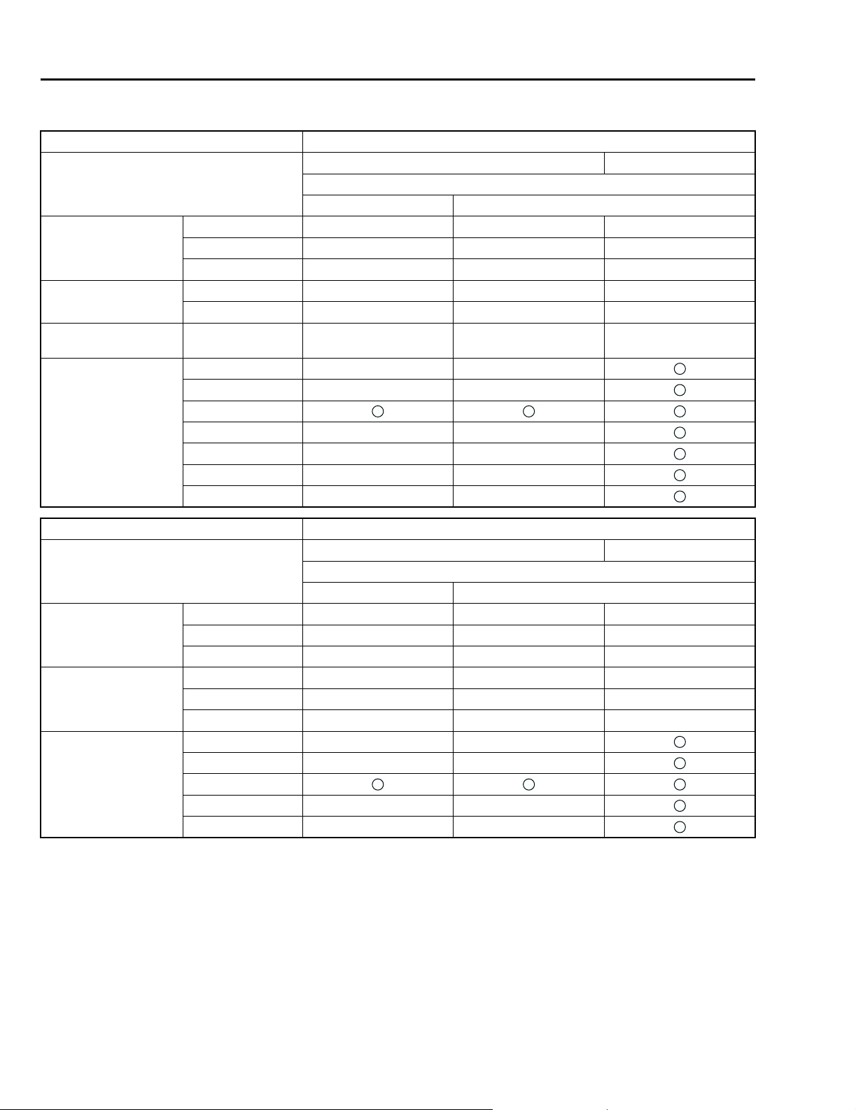
A: DIMENSIONS
Model OUTBACK
AWD
Overall length mm (in) 4,720 (185.8)
Overall width mm (in) 1,745 (68.7)
Overall height (at CW) mm (in) 1,580 (62.2), 1,590 (62.6)*3
Compartment Length mm (in) 1,925 (75.8)
Width mm (in) 1,440 (56.7), 1,420 (55.9)*1
Height mm (in) 1,190 (46.9), 1,175 (46.3)*2
Wheelbase mm (in) 2,650 (104.3)
Tread Front mm (in) 1,470 (57.9)
Rear mm (in) 1,460 (57.5)*3, 1,465 (57.7)
Minimum road
clearance
Without catalytic
converter
With catalytic
converter
Australia mm (in) 200 (7.9)
mm (in) 195 (7.7)
mm (in) 190 (7.5)
*1: With leather seat
*2: With sunroof
*3: Australia spec. vehicles
B: ENGINE
Model OUTBACK
AWD
2.5 L 3.0 L
Engine type Horizontally opposed, liquid cooled,
4-cylinder, 4-stroke gasoline engine
Valve arrangement Overhead camshaft type Double overhead camshaft type
Bore × Stroke mm (in) 99.5 × 79.0 (3.917 × 3.110) 89.2 × 80.0 (3.512 × 3.150)
Displacement cm
Compression ratio 10.0 10.7
Firing order 1 — 3 — 2 — 41 — 6 — 3 — 2 — 5 — 4
Idle speed at Park/Neutral
position
Maximum output kW (HP)/rpm 115 (154)/5,600 154 (206)/6,000
Maximum torque N·m (kgf-m, ft-lb)/rpm 223 (22.7, 164.2)/3,600 282 (28.8, 208)/4,400
3
(cu in) 2,457 (149.9) 3,000 (183.06)
rpm 700±100 600±100
Horizontally opposed, liquid cooled,
6-cylinder, 4-stroke gasoline engine
SPC-10
Page 15

OUTBACK
Specifications
C: ELECTRICAL
Model OUTBACK
AWD
2.5 L 3.0 L
Ignition timing at idling speed BTDC/rpm 10°±10°/700 10°±8°/600
Spark plug Type and manufacturer RC10YC4 ....... CHAMPION PLFR6A ....... NGK
Alternate RC8YC4 ....... CHAMPION
Generator 12V — 90A 12V — 100A
Battery Type and capacity (5HR) For Europe and
South America
Others 12V — 27AH (34B19L) 12V — 48H (55D23L)
BKR6E-11 ....... NGK
K20PR-U11 ....... NIPPONDENSO
MT: 12V — 48AH (55D23L)
AT: 1 2V — 52AH (75D23L)
12V — 52AH (75D23L)
D: TRANSMISSION
Model OUTBACK
AWD
2.5 L 3.0 L
Transmission type 5MT 4AT 4AT
Clutch type DSPD TCC TCC
Gear ratio 1st 3.454 2.785
2nd 2.062 1.545
3rd 1.448 1.000
4th 1.088 0.694
5th 0.825 —
Reverse 3.333 2.272
Auxiliary transmission gear ratio High 1.000 —
Low 1.196 —
Reduction gear
(Front drive)
Reduction gear
(Rear drive)
1st reduction Type of gear — Helical
Gear ratio — 1.000
Final reduction Type of gear Hypoid Hypoid
Gear ratio 3.900*1, 4.111*2 4.444 4.111
Tr a n sf e r
reduction
Final reduction Type of gear Hypoid Hypoid
Type of gear Helical —
Gear ratio 1.000 —
Gear ratio 3.900*1, 4.111*2 4.444 4.111
5MT: 5 × 2 forward speeds with synchromesh and 1-reverse
4AT: Electronically controlled fully-automatic, 4-forward speeds and 1-reverse
DSPD: Dry Single Plate Diaphragm
TCC: Torque Converter Clutch
*1: Except Australia spec. vehicles
*2: Australia spec. vehicles
SPC-11
Page 16

OUTBACK
Specifications
E: STEERING
Model OUTBACK
Ty pe Rack and Pinion
Turns, lock to lock 3.0
Minimum turning circle m (ft) Curb to curb: 11.2±1.0 (36.7±3.3)
Wall to wall: 12.0±1.0 (39.4±3.3)
F: SUSPENSION
Model OUTBACK
Front Macpherson strut type, Independent, Coil spring
Rear Multi-link type, Independent, Coil spring
G: BRAKE
Model OUTBACK
Service brake system Dual circuit hydraulic with vacuum suspended power unit
Front Ventilated disc brake
Rear Disc brake
Parking brake Mechanical on rear brakes
H: TIRE
Model OUTBACK
Rim size 16 × 6½JJ
Tire size 215/60R16
Type Steel belted radial, Tubeless
I: CAPACITY
Model OUTBACK
AWD
2.5 L 3.0 L
5MT 4AT
Fuel tank (US gal, Imp gal) 64 (16.9, 14.1)
Engine oil Total capacity (US qt, Imp qt) 4.0 (4.2, 3.5) 6.8 (7.2, 6.0)
Engine oil
amount for refill
Transmission gear oil (US qt, Imp qt) 4.0 (4.2, 3.5) —
Automatic transmission fluid (US qt, Imp qt) — 9.3 – 9.6 (9.8 – 10.1, 8.2 – 8.4)
AT differential gear oil (US qt, Imp qt) — 1.1 – 1.3 (1.2 – 1.4, 1.0 – 1.1)
AWD rear differential gear oil (US qt, Imp qt) 0.8 (0.8, 0.7)
Power steering fluid (US qt, Imp qt) 0.7 (0.7, 0.6)
Engine coolant (US qt, Imp qt) 6.8 (7.2, 6.0) 6.7 (7.1, 5.9) 7.7 (8.1, 6.8)
(US qt, Imp qt) Approx. 4.0 (4.2, 3.5) Approx. 5.8 (6.1, 5.1)
SPC-12
Page 17
OUTBACK
Specifications
J: WEIGHT
1. OUTBACK
! LHD Vehicle
Option code *1 K4 KS KO
Model 2.5 L
4WD
5MT 4AT 5MT 4AT
Curb weight (C.W.) Front kg (lb) 810 (1,785) 825 (1,820) 815 (1,795) 830 (1,830) 785 (1,730)
Rear kg (lb) 670 (1,475) 670 (1,475) 670 (1,475) 670 (1,475) 650 (1,435)
Total kg (lb) 1,480 (3,265) 1,495 (3,295) 1,485 (3,275) 1,500 (3,310) 1,435 (3,165)
Maximum permissible
axle weight (M.P.A.W.)
Maximum permissible
weight (M.P.W.)
Option Side airbag —————
Front kg (lb) 995 (2,195) 995 (2,195) 995 (2,195) 995 (2,195) 960 (2,115)
Rear kg (lb) 1,050 (2,315) 1,050 (2,315) 1,050 (2,315) 1,050 (2,315) 1,030 (2,270)
Total kg (lb) 2,000 (4,410) 2,000 (4,410) 2,000 (4,410) 2,000 (4,410) 1,920 (4,235)
Air conditioner
Audio ——
Cruise control
Cold weather pack —————
Leather interior ————
Sunroof ————
Option code *1 EC
Model 2.5 L 3.0 L
4WD
5MT 4AT
Curb weight (C.W.) Front kg (lb) 815 (1,795) 830 (1,830) 915 (2,020)
Rear kg (lb) 675 (1,490) 675 (1,490) 695 (1,530)
Total kg (lb) 1,490 (3,285) 1,505 (3,320) 1,610 (3,550)
Maximum permissible
axle weight (M.P.A.W.)
Maximum permissible
weight (M.P.W.)
Option Side airbag
*1: For option code, refer to ID section. <Ref. to ID-5, MODEL NUMBER PLATE, IDENTIFICATION, Identification.>
Front kg (lb) 1,010 (2,225) 1,010 (2,225) 1,040 (2,295)
Rear kg (lb) 1,060 (2,335) 1,060 (2,335) 1,060 (2,335)
Total kg (lb) 2,015 (4,445) 2,015 (4,445) 2,085 (4,595)
Air conditioner
Audio ——
Cruise control ——
Cold weather pack ——
Leather interior ——
Sunroof ——
SPC-13
Page 18
OUTBACK
Specifications
! RHD Vehicle
Option code *1 EK
Model 2.5 L 3.0 L
4WD
5MT 4AT
Curb weight (C.W.) Front kg (lb) 800 (1,765) 815 (1,795) 915 (2,020)
Rear kg (lb) 670 (1,475) 670 (1,475) 695 (1,530)
Total kg (lb) 1,470 (3,240) 1,485 (3,275) 1,610 (3,550)
Maximum permissible
axle weight (M.P.A.W.)
Maximum permissible
weight (M.P.W.)
Option Side airbag ——
Front kg (lb) 1,010 (2,225) 1,010 (2,225) 1,040 (2,295)
Rear kg (lb) 1,060 (2,335) 1,060 (2,335) 1,060 (2,335)
Total kg (lb) 2,015 (4,445) 2,015 (4,445) 2,085 (4,595)
Air conditioner ——
Audio
Cruise control ——
Cold weather pack ——
Leather interior ——
Sunroof ——
Option code *1 KA
Model 2.5 L 3.0 L
4WD
5MT 4AT
Unladen mass (U.M.) Front kg (lb) 790 (1,740) 800 (1,765) 900 (1,985)
Rear kg (lb) 650 (1,435) 650 (1,435) 690 (1,520)
Total kg (lb) 1,440 (3,175) 1,410 (3,110) 1,590 (3,505)
Gross vehicle mass
(G.V.M.)
Option Side airbag ——
*1: For option code, refer to ID section. <Ref. to ID-5, MODEL NUMBER PLATE, IDENTIFICATION, Identification.>
Front kg (lb) 970 (2,140) 970 (2,140) 1,035 (2,280)
Rear kg (lb) 1,050 (2,315) 1,050 (2,315) 1,050 (2,315)
Total kg (lb) 2,020 (4,455) 2,020 (4,455) 2,085 (4,595)
Air conditioner ——
Audio
Cruise control ——
Cold weather pack ——
SPC-14
Page 19

OUTBACK
Specifications
NOTE:
When any of the following optional parts are installed, add the weight to the curb weight.
Weight of
optional parts
Front kg (lb) 2.1 (4.6) 0.2 (0.4) 13.9 (30.6) 10.9 (24.0) 1.8 (4.0)
Rear kg (lb) 0.3 (0.7) 4.2 (9.3) –0.1 (–0.2) 16.4 (36.2) 3.1 (6.8)
Total kg (lb) 2.4 (5.3) 4.4 (9.7) 13.8 (30.4) 27.3 (60.2) 4.9 (10.8)
Weight of
optional parts
Front kg (lb) 2.9 (6.4) 0.2 (0.44) 1.8 (4.0) –0.7 (–1.54) –1.4 (–3.09)
Rear kg (lb) 3.0 (6.6) 0.2 (0.44) 0.7 (1.5) 3.2 (7.06) –3.8 (–8.38)
Total kg (lb) 5.9 (13.0) 0.4 (0.88) 2.5 (5.5) 2.5 (5.51) –5.2 (–11.47)
Cruise control Self
levelizer
SRS Airbag (Side) Cold weather pack Audio Rear spoiler Sports package
Air conditioner Sunroof Leather interior
SPC-15
Page 20

Specifications
MEMO
OUTBACK
SPC-16
Page 21

FUEL INJECTION (FUEL SYSTEM) FU
Page
1. General ............................................................................................................ 2
2. Air Line ............................................................................................................ 3
3. Fuel Line .......................................................................................................... 8
4. Sensors and Switches .....................................................................................19
5. Control System ................................................................................................ 30
6. On-board Diagnosis System ...........................................................................38
Page 22

GENERAL
Fuel Injection (Fuel System)
1. General
! The Multipoint Fuel Injection (MFI) system supplies optimum air-fuel mixture under every engine
operating condition through the use of the latest electronic control technology.
This system pressurizes the fuel to a constant pressure and injects it into each intake air port in
the cylinder head. The injection quantity of fuel is controlled by an intermittent injection system
where an electro-magnetic injection valve or injector opens for a short period that is precisely controlled depending on the quantity of air appropriate for each condition of operation. In actual control, an optimum fuel injection quantity is achieved by varying the duration of an electric pulse
applied to the injector. This way of control enables simple, yet highly precise metering of the fuel.
! The engine control module (ECM) that controls the fuel injection system corrects the fuel injec-
tion amount depending on the vehicle speed, throttle opening, coolant temperature and other vehicle-operation-related information. The ECM receives the information in the form of electric
signals from the corresponding sensors and switches.
The MFI system also has the following features:
! Reduced exhaust emissions
! Reduced fuel consumption
! Increased engine output
! Quick response to accelerator and brake pedal operation
! Superior startability and warm-up performance in cold weather due to corrective controls made
according to coolant and intake air temperatures
FU-2
Page 23
AIR LINE
Fuel Injection (Fuel System)
2. Air Line
A: GENERAL
The air filtered by the air cleaner enters the throttle body where it is regulated in the volume by the
throttle valve and then enters the intake manifold. It is then distributed to each cylinder where the
air is mixed with fuel injected by the injector. During idling operation, air flows into the cylinder
through the idle air control solenoid valve, bypassing the throttle valve. This enables controlling the
engine idling speed properly.
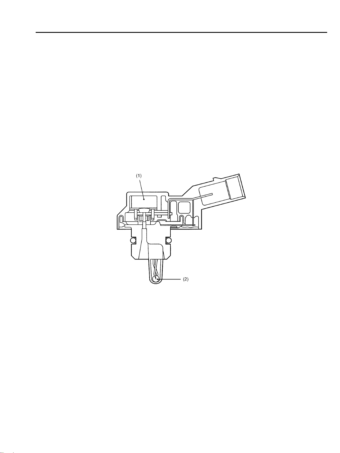
B: INTAKE MANIFOLD PRESSURE AND AIR TEMPERATURE SENSORS
The intake manifold pressure sensor and the intake air temperature sensor are integrated into a
single unit. The unit is mounted on the intake manifold and measures the absolute air pressure in
the intake manifold as well as the temperature of the intake air.
The measured pressure and temperature are converted into electrical signals and sent to the
ECM. The ECM uses these signals to control injection and ignition timing as well as the fuel injection amount.
(1) Pressure sensor
(2) Intake air temperature sensor
H2H2825B
FU-3
Page 24
AIR LINE
Fuel Injection (Fuel System)
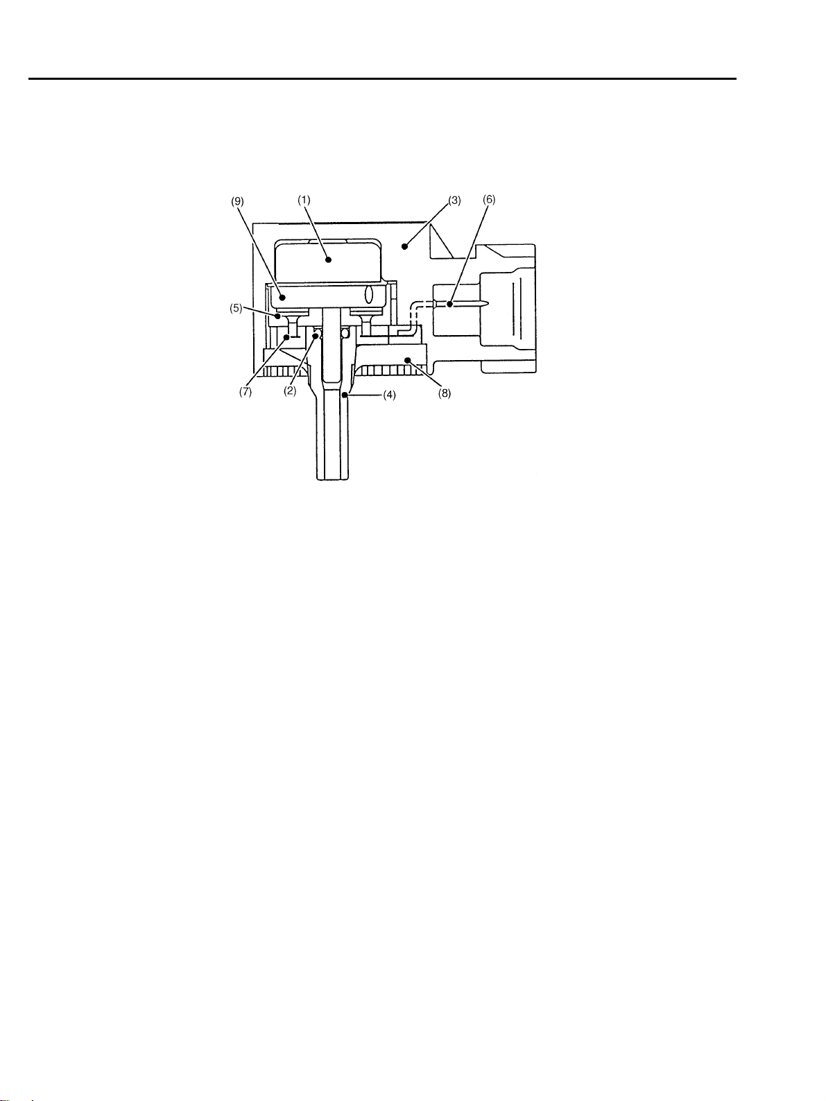
C: ATMOSPHERIC PRESSURE SENSOR
The atmospheric pressure sensor converts pressure values into electric signals, and sends the
signals to the ECM.
H2H1869B
(1) Sensor unit (6) Terminal
(2) O-ring (7) Inner lead
(3) Case (8) Resin
(4) Pipe (9) Metal lid
(5) Through capacity
D: THROTTLE BODY
In response to operation of the accelerator pedal, the throttle valve in the throttle body opens/closes to regulate the volume of the air drawn into the combustion chamber.
During idling, the throttle valve is almost fully closed and the volume of air passing through the
throttle body is less than that passing through the idle air control solenoid valve.
More than half of the air necessary for idling is supplied to the intake manifold via the idle air control solenoid valve which controls properly the engine idling speed, so the idling speed needs not
be adjusted.
FU-4
Page 25
AIR LINE
Fuel Injection (Fuel System)
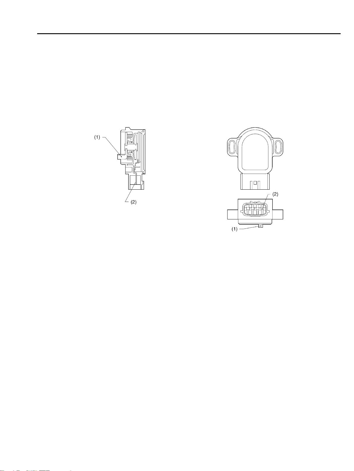
E: THROTTLE POSITION SENSOR
! The throttle position sensor is mounted in the throttle body and linked to the throttle valve.
! The throttle position sensor sends the ECM voltage signal corresponding to the opening of the
throttle valve. When the sensor’s output voltage exceeds a predetermined level, the ECM interprets it as complete closure of the throttle valve. When the output voltage is at another predetermined level, the ECM recognizes that the throttle valve is at a wide open position. Since the output
characteristics of the sensor change over years, the ECM is provided with a learning function to
be able to interpret signals into throttle valve angles always correctly.
(1) Lever
(2) Terminal
B2H2004B
FU-5
Page 26
AIR LINE
Fuel Injection (Fuel System)
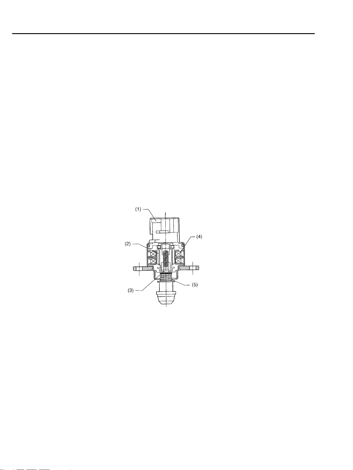
F: IDLE AIR CONTROL SOLENOID VALVE
! The idle air control solenoid valve is located in the throttle body and regulates the amount of
intake air that flows bypassing the throttle valve into the intake manifold during engine idling. It is
activated by a signal from the ECM in order to maintain the engine idling speed at a target speed.
! The idle air control solenoid valve is a stepping motor type solenoid-actuated valve which con-
sists of coils, a shaft, a permanent magnet, a spring and a housing. The housing is an integral part
of the throttle body.
! The stepping motor consists of two paired coils, the coils of each pair being arranged face to
face with a shaft in between.
! The shaft has a screw at the end around which the permanent magnets are arranged.
! As current flows in the form of pulses through the paired coils sequentially while alternating the
polarity, the N and S poles of the permanent magnets around the shaft are repelled by the same
poles of the magnetism generated by the coils. This causes a nut externally fixed to the magnets
and internally engaging with the screw of the shaft to turn.
The shaft then goes upward or downward.
! This upward and downward motions of the shaft open or close the valve port, adjusting the
amount of bypass air.
(1) Connector
(2) Permanent magnet
(3) Shaft
(4) Coil
(5) Spring
B2H2005B
FU-6
Page 27
AIR LINE
Fuel Injection (Fuel System)
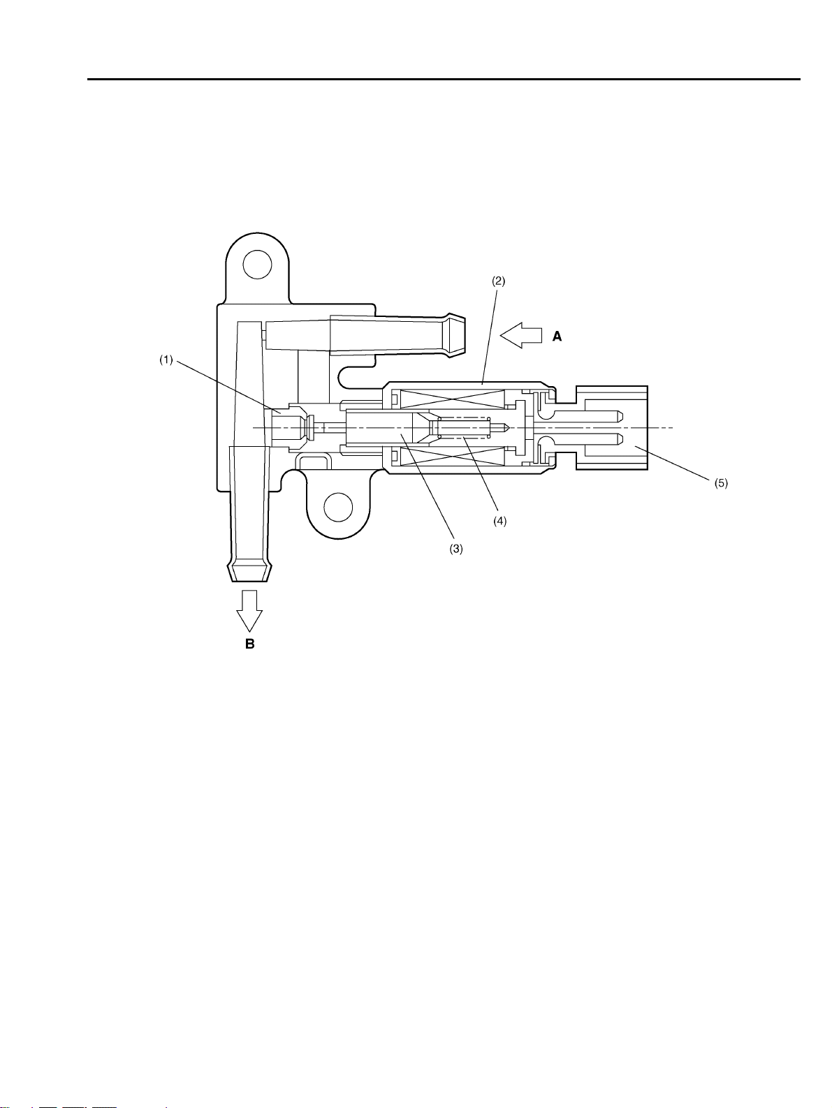
G: AIR ASSIST INJECTOR SOLENOID VALVE
The air assist injector solenoid valve is located in the piping between the throttle body and the injector and secured to the intake manifold.
This solenoid valve is opened or closed by the signals from the ECM, adjusting the flow rate of air
supplied to the injector.
(1) Valve seat A: From idle air control solenoid valve
(2) Solenoid B: To inj ec to r
(3) Plunger and valve
(4) Spring
(5) Connector
FU-7
B2H3447B
Page 28
FUEL LINE
Fuel Injection (Fuel System)
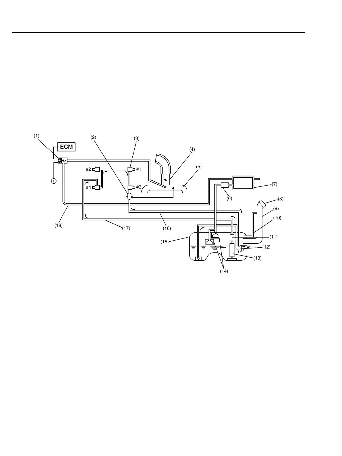
3. Fuel Line
A: GENERAL
! The fuel pressurized by the fuel tank inside pump is delivered to each fuel injector by way of the
fuel pipe and fuel filter. Fuel injection pressure is regulated to an optimum level by the pressure
regulator.
! Each injector injects fuel into the intake port of the corresponding cylinder where the fuel is
mixed with air. The mixture then enters the cylinder.
Fuel injection amount and timing are regulated by the ECM.
(1) Purge control solenoid valve (10) Air vent pipe
(2) Pressure regulator (11) Fuel filter
(3) Fuel injector (12) Jet pump
(4) Throttle body (13) Fuel pump
(5) Intake manifold (14) Fuel cut valve
(6) Two-way valve (15) Fuel tank
(7) Canister (16) Fuel return line
(8) Filler cap (17) Fuel delivery line
(9) Filler pipe (18) Fuel evaporation line
FU-8
B2H2907B
Page 29
FUEL LINE
Fuel Injection (Fuel System)
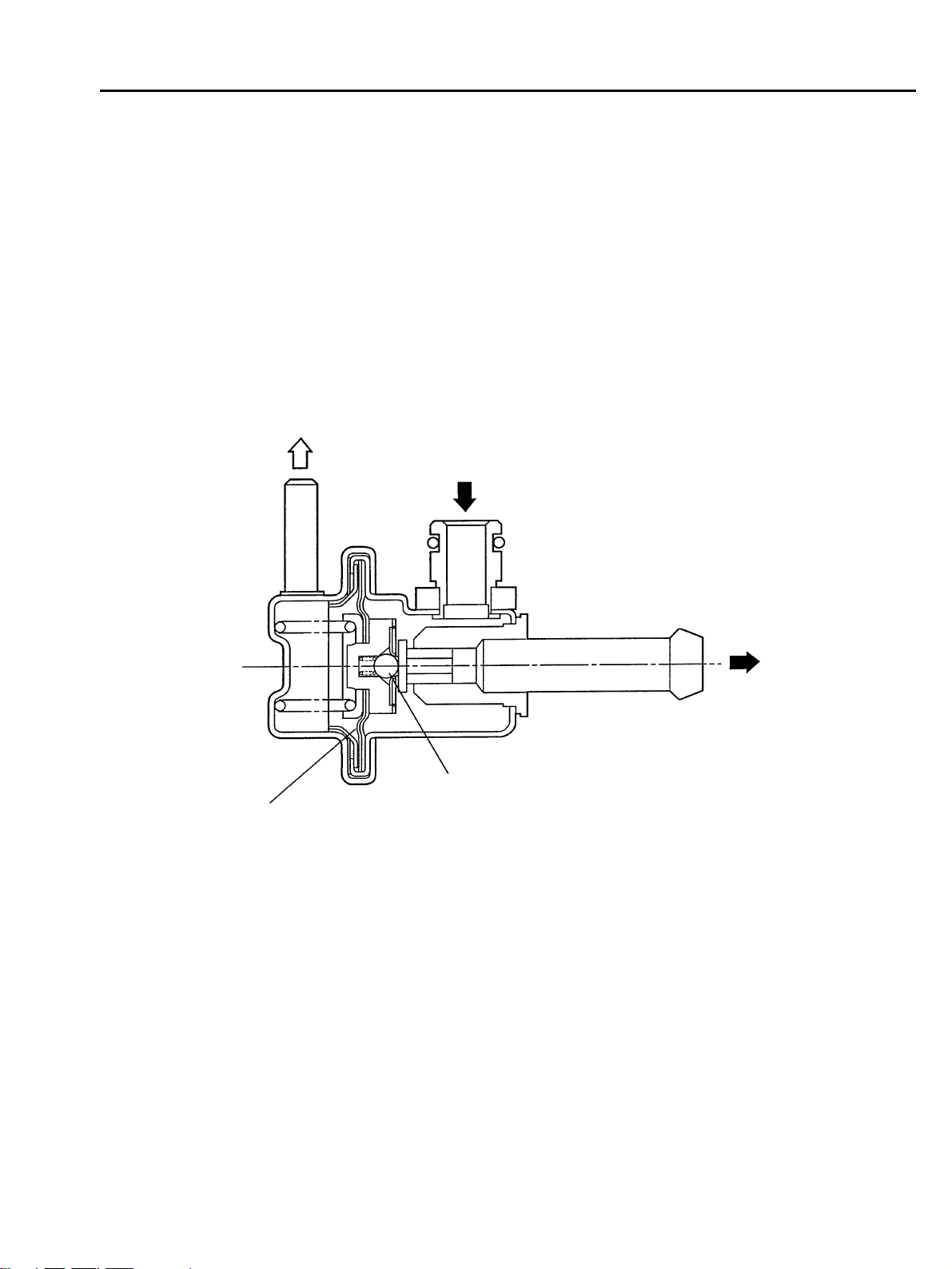
B: PRESSURE REGULATOR
The pressure regulator is installed at the injector end of the fuel supply line. It has a fuel chamber
and spring chamber separated by a diaphragm. Fuel chamber is connected to the fuel supply line
and the spring chamber is connected to the intake manifold. Fuel chamber also has a relief valve
connected to the fuel return line through which fuel returns to the fuel tank. When the intake manifold vacuum increases, the diaphragm is pulled and the relief valve opens to decrease the fuel
supply line pressure (or fuel injection pressure). When the intake manifold vacuum decreases, the
diaphragm is pushed by the spring to increase the fuel supply line pressure. Thus, the difference
between the fuel injection pressure and the intake manifold vacuum is kept at a constant level of
294 kPa (3.00 kgf/cm
hicles to precisely control the amount of injected fuel.
2
, 43.0 psi) for MT vehicles or 299.1 kPa (3.05 kgf/cm2, 43.4 psi) for AT ve-
A
B
(1)
(2)
(1) Relief valve A: To intake manifold
(2) Diaphragm B: Fuel IN
C: Fuel OUT
C
S2H0623C
FU-9
Page 30

FUEL LINE
Fuel Injection (Fuel System)
C: FUEL INJECTORS
! The MFI system employs top feed type fuel injectors with an air assist feature.
! Each injector is installed in the fuel pipe in such a way that the injector is cooled by fuel.
! The features of this type of fuel injector are as follows:
1) High heat resistance
2) Low driving noise
3) Easy to service
4) Small size
! The injector injects fuel according to the valve open signal from the ECM. The needle valve is
lifted by the solenoid which is energized on arrival of the valve open signal.
! Since the injector’s nozzle hole area, the lift of valve and the fuel pressure are kept constant,
the amount of fuel injected is controlled only by varying the duration of the valve open signal from
the ECM.
! Fuel atomization is enhanced using assist air supplied from the idle air control solenoid valve
passing through the passage formed in the intake manifold at the area in which each injector is
installed. This contributes not only to higher combustion efficiency and higher output but also to
cleaner exhaust emissions.
FU-10
Page 31

FUEL LINE
Fuel Injection (Fuel System)
(1) Filter (4) Seal
(2) O-ring (5) O-ring
(3) Plunger (6) Connector
S2H1943A
FU-11
Page 32

FUEL LINE
Fuel Injection (Fuel System)
D: FUEL TANK
The fuel tank utilizes a two-compartment design to ensure sufficient capacity without interfering
with the rear differential. It is provided with a suction jet pump (included in the fuel pump and fuel
level sensor assembly) which transfers fuel from one compartment to the other. Each compartment has an individual fuel level sensor.
(5)
(1)
(6)
A
(2)
(3)
(4)
(1) Fuel pump and fuel level sensor assembly (5) Quick connector
(2) Nylon tube (6) Fuel cut valve (Main compartment)
(3) Fuel cut valve (Sub-compartment)
(4) Fuel level sensor (Sub-compartment) A: To two way valve
(5)
B2H2908C
FU-12
Page 33

FUEL LINE
Fuel Injection (Fuel System)
The fuel tank is located under the rear seat and secured with hold-down bands.
(1)
(2)
(1) Band
(2) Cushion
(3) Steel
(3)
B2H2913C
FU-13
Page 34

FUEL LINE
Fuel Injection (Fuel System)
E: FUEL PUMP AND FUEL LEVEL SENSOR ASSEMBLY
1. FUEL PUMP
The fuel pump consists of a motor, impeller, pump casing, pump cover, check valve and filter. It is
located in the fuel tank and combined with the fuel level sensor into a single unit. The operation of
this impeller type pump is very quiet.
E
B
A
C
(1)
(2)
(3)
(7)
(8)
(9)
(1) Fuel level sensor (7) Pump casing A: To engine (delivery line)
(2) Fuel pump (8) Fuel passage B: From engine (return line)
(3) Pump cover (9) Impeller C: From sub tank
(4) Jet pump (10) Motor armature D: Suction
(5) Cartridge filter (11) Check valve E: Discharge
(6) Mesh filter
(4)
(5)
(6)
D
(10)
(7)
(11)
(9)
D
B2H2909C
FU-14
Page 35

FUEL LINE
Fuel Injection (Fuel System)
! When the ignition switch is turned ON, fuel pump relay is activated. Then the motor operates to
rotate the impeller.
! As the impeller rotates, fuel in a vane groove of the impeller flows along the fuel passage into
the next vane groove by centrifugal force. When fuel flows from one groove to the next, a pressure
difference occurs due to friction. This creates a pumping effect.
! The fuel pushed up by rotation of the impeller then passes through the clearance between the
armature and the magnet of the motor and is discharged through the check valve.
! When the fuel discharge pressure reaches the specified level, the relief valve opens and excess
fuel is released into the fuel tank. In this manner, the relief valve prevents an abnormal increase
in fuel pressure.
! When the engine and the fuel pump stop, spring force acts on the check valve to close the dis-
charge port, so that the fuel pressure in the fuel delivery line is retained.
FU-15
Page 36

FUEL LINE
Fuel Injection (Fuel System)
2. JET PUMP
! The jet pump utilizes the velocity of fuel returning from the engine to produce negative pressure
in it.
! Using the pumping effect produced by the negative pressure, the jet pump transfers fuel from
the sub-compartment to the main compartment of the fuel tank.
! When the return line nozzle is clogged, the fuel sent back through the return line flows back into
the fuel tank via the relief valve.
(1)
B
(1)
A
(2)
(3)
(4)
A
(1) Jet pump A: Return line
(2) Relief valve B: From sub tank compartment
(3) Silencer
(4) Nozzle
FU-16
B2H2911C
Page 37

FUEL LINE
Fuel Injection (Fuel System)
3. FUEL FILTERS
There are two different types of fuel filters inside fuel tank, forming integral part of the fuel pump.
The filter at the inlet of the fuel pump is a mesh type which removes relatively large particles in the
fuel before it enters the pump. The filter at the outlet of the pump is a pressure resistant cartridge
type whose inside filtering element can remove small particles in the pressurized fuel.
(1)
(2)
(3)
(1) Fuel pump
(2) Cartridge filter
(3) Mesh filter
B2H2910D
FU-17
Page 38

FUEL LINE
Fuel Injection (Fuel System)
F: SUB-COMPARTMENT FUEL LEVEL SENSOR
This sensor detects the level of the fuel in the sub-compartment (the compartment in which the
fuel pump is not located) and acts as part of the fuel transfer line when the jet pump is in operation
to maintain the fuel in both compartments at the same level.
(3)
(1)
(2)
(1) Fuel level sensor (Sub) (3) To jet pump
(2) Float
B2H2912B
FU-18
Page 39

SENSORS AND SWITCHES
4. Sensors and Switches
A: FRONT OXYGEN (A/F) SENSOR
Fuel Injection (Fuel System)
! The front oxygen sensor uses zirconium oxide (ZrO
) which is a solid electrolyte, at portions ex-
2
posed to exhaust gas.
! The zirconium oxide has the property of generating electromotive force when its both sides are
exposed to oxygen ions of different concentration and the magnitude of this electromotive force
depends on how much the difference is.
! The front oxygen sensor detects the amount of oxygen in exhaust gases by making use of this
property of the zirconium oxide material.
! The zirconium oxide material is formed into a closed end tube and its external surface is ex-
posed to exhaust gases with smaller oxygen ion concentration, whereas its internal surface is exposed to atmospheric air. The external surface has a porous platinum coating. The sensor housing
is grounded to the exhaust pipe and the inside is connected to the ECM through the harness to
be able to use the current output from the sensor.
! The sensor incorporates a ceramic heater to improve its performance at low temperatures.
(1) Sensor element
(2) Sensor housing
(3) Protection tube
(4) Gasket
S2H1791B
FU-19
Page 40

SENSORS AND SWITCHES
Fuel Injection (Fuel System)
! When rich air-fuel mixture is burnt in the cylinder, the oxygen in the exhaust gases is almost
completely used in the catalytic reaction by the platinum coating on the external surface of the zirconia tube. This results in a very large difference in the oxygen ion concentration between the inside and outside of the tube, and the electromotive force generated is large.
! When a lean air-fuel mixture is burnt in the cylinder, relatively large amount of oxygen remains
in the exhaust gases even after the catalytic action, and this results in a small difference in the
oxygen ion concentration between the tube’s internal and external surfaces. The electromotive
force in this case is very small.
! The difference in oxygen concentration changes drastically in the vicinity of the stoichiometric
air-fuel ratio, and hence the change in the electromotive force is also large. By using this information, the ECM can determine the air-fuel ratio of the supplied mixture easily. The front oxygen sensor does not generate much electromotive force when the temperature is low. The output
characteristics of the sensor stabilize at a temperature of approximately 700°C (1,292°F).
Atmospheric air
Lean Air-fuel ratio Rich
B2H2006B
FU-20
Page 41

SENSORS AND SWITCHES
Fuel Injection (Fuel System)
B: REAR OXYGEN SENSOR
! The rear oxygen sensor is used to sense oxygen concentration in the exhaust gas. If the air-fuel
ratio is leaner than the stoichiometric ratio in the mixture (i.e., excessive amount of air), the exhaust gas contains more oxygen. To the contrary, if the fuel ratio is richer than the stoichiometric
ratio, the exhaust gas contains almost no oxygen.
! Detecting the oxygen concentration in exhaust gas using the oxygen sensor makes it possible
to determine whether the air-fuel ratio is leaner or richer than the stoichiometry.
! The rear oxygen sensor has a zirconia tube (ceramic) which generates voltage if there is a dif-
ference in oxygen ion concentration between the inside and outside of the tube. Platinum is coated
on the inside and outside of the zirconia tube as a catalysis and electrode material. The sensor
housing is grounded to the exhaust pipe and the inside is connected to the ECM through the harness.
! A ceramic heater is employed to improve performance at low temperatures.
(1) Protection tube (4) Gasket
(2) Ceramic heater (5) Sensor housing
(3) Zirconia tube (6) Harness
B2H3810C
FU-21
Page 42

SENSORS AND SWITCHES
Fuel Injection (Fuel System)
! When rich air-fuel mixture is burnt in the cylinder, the oxygen in the exhaust gases is almost
completely used in the catalytic reaction by the platinum coating on the external surface of the zirconia tube. This results in a very large difference in the oxygen ion concentration between the inside and outside of the tube, and the electromotive force generated is large.
! When a lean air-fuel mixture is burnt in the cylinder, relatively large amount of oxygen remains
in the exhaust gases even after the catalytic action, and this results in a small difference in the
oxygen ion concentration between the tube’s internal and external surfaces. The electromotive
force in this case is very small.
! The difference in oxygen concentration changes drastically in the vicinity of the stoichiometric
air-fuel ratio, and hence the change in the electromotive force is also large. By using this information, the ECM can determine the air-fuel ratio of the supplied mixture easily. The rear oxygen sensor does not generate much electromotive force when the temperature is low. The output
characteristics of the sensor stabilize at a temperature of approximately 300 to 400°C (572 to
752°F).
To be judged
as lean
Lean Air-fuel ratio
Rich
G2H0038B
FU-22
Page 43

SENSORS AND SWITCHES
Fuel Injection (Fuel System)
C: ENGINE COOLANT TEMPERATURE SENSOR
The engine coolant temperature sensor is located on the engine coolant pipe. The sensor uses a
thermistor whose resistance changes inversely with temperature. Resistance signals as engine
coolant temperature information are transmitted to the ECM to make fuel injection, ignition timing,
purge control solenoid valve and other controls.
(1) Connector (2) Thermistor element
S2H1113B
FU-23
Page 44

SENSORS AND SWITCHES
Fuel Injection (Fuel System)
D: CRANKSHAFT POSITION SENSOR
! The crankshaft position sensor is installed on the oil pump which is located in the front center
portion of the cylinder block. The sensor generates a pulse when one of the teeth on the perimeter
of the crankshaft sprocket (rotating together with the crankshaft) passes in front of it. The ECM
determines the crankshaft angular position by counting the number of pulses.
! The crankshaft position sensor is a molded type which consists of a magnet, core, coil, termi-
nals and other components as illustrated below.
(1) Terminal (4) Coil
(2) Yoke core (5) Core
(3) Magnet (6) Cover
B2H0407B
FU-24
Page 45

SENSORS AND SWITCHES
Fuel Injection (Fuel System)
! As the crankshaft rotates, each tooth aligns with the crankshaft position sensor. At that time, the
magnetic flux in the sensor’s coil changes since the air gap between the sensor pickup and the
sprocket changes. This change in magnetic flux induces a voltage pulse in the sensor and the
pulse is transmitted to the ECM.
(1)
A
(2)
(1) Crankshaft position sensor A: Crankshaft half rotation
(2) Crankshaft sprocket
B2H1995C
FU-25
Page 46

SENSORS AND SWITCHES
Fuel Injection (Fuel System)
E: CAMSHAFT POSITION SENSOR
! The camshaft position sensor is located on the left-hand camshaft support. It detects the com-
bustion cylinder at any given moment.
! The sensor generates a pulse when one of the bosses on the back of the left-hand camshaft
drive sprocket passes in front of the sensor. The ECM determines the camshaft angular position
by counting the number of pulses.
Internal construction and the basic operating principle of the camshaft position sensor are similar
to those of the crankshaft position sensor. A total of seven bosses are arranged at equally spaced
four locations (one each at two locations, two at one location, and three at one location) of the
sprocket as shown below.
B2H3812C
(1) Boss A: Camshaft one rotation (Crankshaft two rotations)
(2) Camshaft sprocket B: Cylinder identification signal
(3) Air gap
(4) Camshaft position sensor
FU-26
Page 47

SENSORS AND SWITCHES
Fuel Injection (Fuel System)
F: KNOCK SENSOR
! The knock sensor is installed on the cylinder block, and senses knocking that occurs in the en-
gine.
! The sensor is a piezo-electric type which converts vibration resulting from knocking into electric
signals.
! In addition to a piezo-electric element, the sensor has a weight and case as its components. If
knocking occurs in the engine, the weight in the case moves causing the piezo-electric element to
generate a voltage.
! The knock sensor harness is connected to the bulkhead harness.
(1) Nut A: To knock sensor harness
(2) Weight
(3) Resistor
(4) Housing
(5) Piezo-electric element
B2H1998B
FU-27
Page 48

SENSORS AND SWITCHES
Fuel Injection (Fuel System)
G: VEHICLE SPEED SENSOR
1. MT VEHICLES
! The vehicle speed sensor is mounted on the transmission.
! The vehicle speed sensor generates a 4-pulse signal for every rotation of the front differential
and send it to the ECM and the combination meter.
(1) Combination meter
(2) ECM
(3) Vehicle speed sensor
(4) Transmission
B2H2458C
FU-28
Page 49

SENSORS AND SWITCHES
Fuel Injection (Fuel System)
2. AT VEHICLES
! The vehicle speed sensor is mounted on the transmission.
! The vehicle speed sensor generates a 16-pulse signal for every rotation of the front differential
and send it to the transmission control module (TCM). The signal sent to the TCM is converted
there into a 4-pulse signal, and then sent to the ECM and the combination meter.
(1) Combination meter
(2) ECM
(3) TCM
(4) Vehicle speed sensor
(5) Transmission
B2H2459B
FU-29
Page 50

CONTROL SYSTEM
Fuel Injection (Fuel System)
5. Control System
A: GENERAL
The ECM receives signals from various sensors, switches, and other control modules. Using these
signals, it determines the engine operating conditions and if necessary, emits signals to one or
more systems to control them for optimum operation.
Major control items of the ECM are as follow:
! Fuel injection control
! Ignition system control
! Idle air control
! Canister purge control*
! Radiator fan control*
! Fuel pump control
! On-board diagnosis function
*1: Canister purge control is described under “EC – Emission Control (Aux. Emission Control Devices) Evaporative Emission Control System”.
1
2
*2: Radiator fan control is described under “CO – Cooling”.
FU-30
Page 51

CONTROL SYSTEM
B: INPUT AND OUTPUT SIGNALS
Signal Unit Function
Input signals
Output signals
Intake air temperature and pressure
sensor
Atmospheric pressure sensor Detects the amount of intake air (Measure the atmospheric pressure).
Throttle position sensor Detects the throttle valve position.
Front oxygen (A/F) sensor Detects the density of oxygen in exhaust gases at the upstream of the
Rear oxygen sensor Detects the density of oxygen in exhaust gases at the downstream of
Crankshaft position sensor Detects the crankshaft angular position.
Camshaft position sensor Detects the combustion cylinder.
Engine coolant temperature sensor Detects the engine coolant temperature.
Knock sensor Detects engine knocking.
Vehicle speed sensor Detects the vehicle speed.
Ignition switch Detects operation of the ignition switch.
Starter switch Detects the condition of engine cranking.
Neutral position switch (MT) Detects that the gear is in neutral.
Park/Neutral position switch (AT) Detects shift positions.
Torque control signal (AT) Controls engine torque.
Heater circuit of front and rear oxygen
sensor
Fuel level sensor Detects the level of the fuel in the fuel tank.
Diagnostics of AT-ECU Detects the self-diagnostics of the AT-ECU.
A/C switch Detects ON-OFF operation of the A/C switch.
Small light switch Detects ON-OFF operation of the small light switch.
Blower fan switch Detects ON-OFF operation of the blower fan switch.
Rear defogger switch Detects ON-OFF operation of the rear defogger switch.
Fuel Injector Activates an injector.
Ignition signal Turns the primary ignition current ON or OFF.
Fuel pump relay Turns the fuel pump relay ON or OFF.
A/C control relay Turns the A/C control relay ON or OFF.
Radiator fan control relay Turns the radiator fan control relay ON or OFF.
Idle air control solenoid valve Adjusts the amount of air flowing through the bypass line in the throttle
Malfunction indicator lamp Indicates existence of abnormality.
Purge control solenoid valve Controls purge of evaporative gas absorbed by the canister.
Power supply Control ON/OFF of the main power supply relay.
Detects the temperature of intake and amount of intake air (Measures
the absolute pressure).
front catalytic converter.
the front catalytic converter.
Detects abnormality in the heater circuit of the front and rear oxygen
sensors.
body.
Fuel Injection (Fuel System)
FU-31
Page 52

CONTROL SYSTEM
Fuel Injection (Fuel System)
C: FUEL INJECTION COTROL
! The ECM receives signals from various sensors and based on them, it determines the amount
of fuel injected and the fuel injection timing. It performs the sequential fuel injection control over
the entire engine operating range except during start-up of the engine.
! The amount of fuel injected depends upon the length of time the injector stays open. The fuel
injection duration is determined according to varying operating condition of the engine. For the
purpose of achieving highly responsive and accurate fuel injection duration control, the ECM performs a new feedback control that incorporates a learning feature as detailed later.
! The sequential fuel injection control is performed such that fuel is injected accurately at the time
when the maximum air intake efficiency can be achieved for each cylinder (i.e., fuel injection is
completed just before the intake valve begins to open).
1. FUEL INJECTION DURATION
Fuel injection duration is basically determined as indicated below:
! During engine start-up:
The duration defined below is used.
! Duration of fuel injection during engine start-up ..... Determined according to the engine cool-
ant temperature detected by the engine coolant temperature sensor.
! During normal operation:
The duration is determined as follows:
Basic duration of fuel injection x Correction factors + Voltage correction time
! Basic duration of fuel injection ..... The basic length of time fuel is injected. This is determined
by two factors – the amount of intake air detected by the manifold pressure sensor and the engine speed monitored by the crankshaft position sensor.
! Correction factors ..... See the next section.
! Voltage correction time ..... This is added to compensate for the time lag before operation of
injector that results from variation in the battery voltage.
FU-32
Page 53

CONTROL SYSTEM
Fuel Injection (Fuel System)
2. CORRECTION FACTORS
The following factors are used to correct the basic duration of fuel injection in order to make the
air-fuel ratio meet the requirements of varying engine operating conditions:
! Air-fuel ratio feedback factor:
This factor is used to correct the basic duration of fuel injection in relation to the actual engine
speed. (See the next section for more detail.)
! Start increment factor:
This factor is used to increase the fuel injection duration only while the engine is being cranked to
improve its startability.
! Coolant-temperature-dependent increment factor:
This factor is used to increase the fuel injection duration depending on engine coolant temperature
signals to facilitate cold starting. The lower the coolant temperature, the greater the increment.
! After-start increment factor:
! This factor is used to increase the fuel injection duration for a certain period immediately after
start of the engine to stabilize engine operation.
! The increment depends on the coolant temperature at the start of the engine.
! Wide-open-throttle increment factor:
This factor is used to increase the fuel injection duration depending on the relationship between
the throttle position sensor signal and manifold pressure sensor signal.
! Acceleration increment factor:
This factor is used to increase the fuel injection duration to compensate for a time lag between air
flow measurement and fuel injection control for better engine response to driver’s pedal operation
during acceleration.
FU-33
Page 54

CONTROL SYSTEM
Fuel Injection (Fuel System)
3. AIR-FUEL RATIO FEEDBACK FACTOR
The ECM creates this factor utilizing the front oxygen sensor signal. When the signal voltage is
low, the air-fuel ratio is richer than the stoichiometric ratio. The ECM then makes the fuel injection
duration shorter by modifying the factor. When the voltage is high showing that the mixture is lean,
the ECM modifies the factor to make the injection duration longer. In this way, the air-fuel ratio is
maintained at a level close to the stoichiometric ratio at which the three-way catalyst acts most
effectively.
B2H0989B
(1) Front catalyst A: Injection duration increment signal
(2) Exhaust gas B: Injection duration decrement signal
(3) Front oxygen (A/F) sensor C: High oxygen density
(4) Fuel injector D: Low oxygen density
(5) Combustion chamber E: Lean signal
(6) ECM F: Rich signal
4. LEARNING FEATURE
The air-fuel ratio feedback control includes a learning feature which contributes to more accurate
and responsive control.
! In the air-fuel ratio feedback control, the ECM calculates the necessary amount of correction
based on data from the oxygen sensor and adds the result to the basic duration (which is stored
in the ECM’s memory for each condition defined by the engine speed and various loads.)
! Without a learning feature, the ECM carries out the above-mentioned process every time. This
means that if the amount of necessary correction is large, the air-fuel ratio feedback control becomes less responsive and less accurate.
! The learning feature enables the ECM to store the amount of correction into memory and add
it to the basic fuel injection duration to create a new reference fuel injection duration. Using the
reference duration as the basic duration for the injection a few times later, the ECM can reduce the
amount of correction and thus make its feedback control more accurate and responsive to changes in the air-fuel ratio due to difference in driving condition and sensor/actuator characteristics that
may result from unit-to-unit variation or aging over time.
FU-34
Page 55

CONTROL SYSTEM
Fuel Injection (Fuel System)
D: IGNITION SYSTEM CONTROL
! The ECM determines operating condition of the engine based on signals from the pressure sen-
sor, engine coolant temperature sensor, intake air temperature sensor, crankshaft position sensor
and other sources. It then selects the ignition timing most appropriate for the condition thus determined from those stored in its memory and outputs at that timing a primary current OFF signal to
the ignitor to initiate ignition.
! This control uses a quick-to-response learning feature by which the data stored in the ECM
memory is processed in comparison with information from various sensors and switches.
! Thus, the ECM can always perform optimum ignition timing taking into account the output, fuel
consumption, exhaust gas, and other factors for every engine operating condition.
! Ignition control during start-up
Engine speed fluctuates during start of the engine, so the ECM cannot control the ignition timing.
During that period, the ignition timing is fixed at 10° BTDC by using the 10° signal from the crankshaft position sensor.
Ignition coil
and ignitor
assembly
B2H3449C
FU-35
Page 56

CONTROL SYSTEM
Fuel Injection (Fuel System)
! Ignition control after start of engine
Between the 97° and 65° crank angle signal, the ECM measures the engine speed, and by using
this data it decides the dwell set timing and ignition timing according to the engine condition.
(1) Cylinder number (5) Ignition timing at normal condition
(2) Crank angle pulse (BTDC) (6) Burning cylinder
(3) Cam angle pulse (ATDC) (7) Dwell set
(4) Ignition timing at starting (8) Ignite
B2H0410D
FU-36
Page 57

CONTROL SYSTEM
Fuel Injection (Fuel System)
E: IDLE AIR CONTROL
! The ECM activates the idle air control solenoid valve to control the bypass air flowing through
the bypass passage in the throttle body depending on signals from the crankshaft position sensor,
engine coolant temperature sensor, pressure sensor and A/C switch so that the proper idle speed
for each engine load is achieved.
! The idle air control solenoid valve uses a duty-ratio-controlled solenoid which can continuously
vary the opening area of the rotary valve. As the ECM increases the duty ratio, opening of the rotary valve increases so that the bypass air flow increases, and the engine idling speed becomes
higher as a result.
! The bypass air control is necessary for:
! Increasing idling speed when the air conditioning system and/or electrical loads are turned
on.
! Increasing idling speed during early stage of warm up period.
! Obtaining dashpot function when the throttle valve is quickly closed.
! Prevention of engine speed variation during idling.
B2H3450C
F: FUEL PUMP CONTROL
Using the signal from the crankshaft position sensor, the ECM controls operation of the fuel pump
by turning its relay ON or OFF. To improve safety, the fuel pump is stopped if the engine stalls with
the ignition switch ON.
Ignition switch ON Fuel pump relay Fuel pump
A certain period of time after ignition switch is turned ON ON Operates
While cranking the engine ON Operates
While engine is operating ON Operates
When engine stops OFF Does not operate
FU-37
Page 58

ON-BOARD DIAGNOSIS SYSTEM
Fuel Injection (Fuel System)
6. On-board Diagnosis System
A: GENERAL
! The on-board diagnosis system detects and indicates a fault by generating a code correspond-
ing to each fault location. The malfunction indicator lamp (CHECK ENGINE light) on the combination meter indicates occurrence of a fault or abnormality.
! When the malfunction indicator lamp comes on as a result of detection of a fault by the ECM,
the corresponding diagnostic trouble code (DTC) and freeze frame engine condition are stored in
the ECM.
! On the OBD-II conformable car, it is necessary to connect the Subaru Select Monitor (SSM) or
General Scan Tool (GST) to the data link connector in order to check the DTC.
! The SSM and GST can read and erase DTCs. They can also read freeze frame data in addition
to other pieces of engine data.
! If there is a failure involving sensors which may affect drive control of the vehicle, the fail-safe
function ensures minimum level of driveability.
B: FAIL-SAFE FUNCTION
For a sensor or switch which has been judged faulty in the on-board diagnosis, the ECM, if appropriate, generates an associated pseudo signal to keep the vehicle operational. (The control becomes degraded.)
FU-38
Page 59

FUEL INJECTION
w/o
(FUEL SYSTEM)
1. General ............................................................................................................ 2
2. Air Line ............................................................................................................ 3
3. Fuel Line .......................................................................................................... 6
4. Sensors and Switches .....................................................................................16
5. Control System ................................................................................................ 25
6. On-board Diagnosis System ...........................................................................33
FU
(
OBD
Page
)
Page 60

GENERAL
Fuel Injection (Fuel System)
1. General
! The Multipoint Fuel Injection (MFI) system supplies optimum air-fuel mixture under every engine
operating condition through the use of the latest electronic control technology.
This system pressurizes the fuel to a constant pressure and injects it into each intake air port in
the cylinder head. The injection quantity of fuel is controlled by an intermittent injection system
where an electro-magnetic injection valve or injector opens for a short period that is precisely controlled depending on the quantity of air appropriate for each condition of operation. In actual control, an optimum fuel injection quantity is achieved by varying the duration of an electric pulse
applied to the injector. This way of control enables simple, yet highly precise metering of the fuel.
! The engine control module (ECM) that controls the fuel injection system corrects the fuel injec-
tion amount depending on the vehicle speed, throttle opening, coolant temperature and other vehicle-operation-related information. The ECM receives the information in the form of electric
signals from the corresponding sensors and switches.
The MFI system also has the following features:
! Reduced exhaust emissions
! Reduced fuel consumption
! Increased engine output
! Quick response to accelerator and brake pedal operation
! Superior startability and warm-up performance in cold weather due to corrective controls made
according to coolant and intake air temperatures
FU-2
Page 61

AIR LINE
Fuel Injection (Fuel System)
2. Air Line
A: GENERAL
The air filtered by the air cleaner enters the throttle body where it is regulated in the volume by the
throttle valve and then enters the intake manifold. It is then distributed to each cylinder where the
air is mixed with fuel injected by the injector. During idling operation, air flows into the cylinder
through the idle air control solenoid valve, bypassing the throttle valve. This enables controlling the
engine idling speed properly.
B: INTAKE MANIFOLD PRESSURE AND AIR TEMPERATURE SENSORS
The intake manifold pressure sensor and the intake air temperature sensor are integrated into a
single unit. The unit is mounted on the intake manifold and measures the absolute air pressure in
the intake manifold as well as the temperature of the intake air.
The measured pressure and temperature are converted into electrical signals and sent to the
ECM. The ECM uses these signals to control injection and ignition timing as well as the fuel injection amount.
H2H2825B
(1) Pressure sensor
(2) Intake air temperature sensor
C: THROTTLE BODY
In response to operation of the accelerator pedal, the throttle valve in the throttle body opens/closes to regulate the volume of the air drawn into the combustion chamber.
During idling, the throttle valve is almost fully closed and the volume of air passing through the
throttle body is less than that passing through the idle air control solenoid valve.
More than half of the air necessary for idling is supplied to the intake manifold via the idle air control solenoid valve which controls properly the engine idling speed, so the idling speed needs not
be adjusted.
FU-3
Page 62

AIR LINE
Fuel Injection (Fuel System)
D: THROTTLE POSITION SENSOR
! The throttle position sensor is mounted in the throttle body and linked to the throttle valve.
! The throttle position sensor sends the ECM voltage signal corresponding to the opening of the
throttle valve. When the sensor’s output voltage exceeds a predetermined level, the ECM interprets it as complete closure of the throttle valve. When the output voltage is at another predetermined level, the ECM recognizes that the throttle valve is at a wide open position. Since the output
characteristics of the sensor change over years, the ECM is provided with a learning function to
be able to interpret signals into throttle valve angles always correctly.
(1) Lever
(2) Terminal
B2H2004B
FU-4
Page 63

AIR LINE
Fuel Injection (Fuel System)
E: IDLE AIR CONTROL SOLENOID VALVE
! The idle air control solenoid valve is located in the throttle body and regulates the amount of
intake air that flows bypassing the throttle valve into the intake manifold during engine idling. It is
activated by a signal from the ECM in order to maintain the engine idling speed at a target speed.
! The idle air control solenoid valve is a stepping motor type solenoid-actuated valve which con-
sists of coils, a shaft, a permanent magnet, a spring and a housing. The housing is an integral part
of the throttle body.
! The stepping motor consists of two paired coils, the coils of each pair being arranged face to
face with a shaft in between.
! The shaft has a screw at the end around which the permanent magnets are arranged.
! As current flows in the form of pulses through the paired coils sequentially while alternating the
polarity, the N and S poles of the permanent magnets around the shaft are repelled by the same
poles of the magnetism generated by the coils. This causes a nut externally fixed to the magnets
and internally engaging with the screw of the shaft to turn.
The shaft then goes upward or downward.
! This upward and downward motions of the shaft open or close the valve port, adjusting the
amount of bypass air.
(1) Connector
(2) Permanent magnet
(3) Shaft
(4) Coil
(5) Spring
B2H2005B
FU-5
Page 64

FUEL LINE
Fuel Injection (Fuel System)
3. Fuel Line
A: GENERAL
! The fuel pressurized by the fuel tank inside pump is delivered to each fuel injector by way of the
fuel pipe and fuel filter. Fuel injection pressure is regulated to an optimum level by the pressure
regulator.
! Each injector injects fuel into the intake port of the corresponding cylinder where the fuel is
mixed with air. The mixture then enters the cylinder.
Fuel injection amount and timing are regulated by the ECM.
(1) Purge control solenoid valve (10) Air vent pipe
(2) Pressure regulator (11) Fuel filter
(3) Fuel injector (12) Jet pump
(4) Throttle body (13) Fuel pump
(5) Intake manifold (14) Fuel cut valve
(6) Two-way valve (15) Fuel tank
(7) Canister (16) Fuel return line
(8) Filler cap (17) Fuel delivery line
(9) Filler pipe (18) Fuel evaporation line
FU-6
B2H2907B
Page 65

FUEL LINE
Fuel Injection (Fuel System)
B: PRESSURE REGULATOR
The pressure regulator is installed at the injector end of the fuel supply line. It has a fuel chamber
and spring chamber separated by a diaphragm. Fuel chamber is connected to the fuel supply line
and the spring chamber is connected to the intake manifold. Fuel chamber also has a relief valve
connected to the fuel return line through which fuel returns to the fuel tank. When the intake manifold vacuum increases, the diaphragm is pulled and the relief valve opens to decrease the fuel
supply line pressure (or fuel injection pressure). When the intake manifold vacuum decreases, the
diaphragm is pushed by the spring to increase the fuel supply line pressure. Thus, the difference
between the fuel injection pressure and the intake manifold vacuum is kept at a constant level of
294 kPa (3.00 kgf/cm
hicles to precisely control the amount of injected fuel.
2
, 43.0 psi) for MT vehicles or 299.1 kPa (3.05 kgf/cm2, 43.4 psi) for AT ve-
A
B
(1)
(2)
(1) Relief valve A: To intake manifold
(2) Diaphragm B: Fuel IN
C: Fuel OUT
C
S2H0623C
FU-7
Page 66

FUEL LINE
Fuel Injection (Fuel System)
C: FUEL INJECTORS
! The MFI system employs top feed type fuel injectors with an air assist feature.
! Each injector is installed in the fuel pipe in such a way that the injector is cooled by fuel.
! The features of this type of fuel injector are as follows:
1) High heat resistance
2) Low driving noise
3) Easy to service
4) Small size
! The injector injects fuel according to the valve open signal from the ECM. The needle valve is
lifted by the solenoid which is energized on arrival of the valve open signal.
! Since the injector’s nozzle hole area, the lift of valve and the fuel pressure are kept constant, the
amount of fuel injected is controlled only by varying the duration of the valve open signal from the
ECM.
(1)
(1) Filter
(2) O-ring
(3) Connector
(3)
(2)
B2H1991B
FU-8
Page 67

FUEL LINE
Fuel Injection (Fuel System)
D: FUEL TANK
The fuel tank utilizes a two-compartment design to ensure sufficient capacity without interfering
with the rear differential. It is provided with a suction jet pump (included in the fuel pump and fuel
level sensor assembly) which transfers fuel from one compartment to the other. Each compartment has an individual fuel level sensor.
(5)
(1)
(6)
A
(2)
(3)
(4)
(1) Fuel pump and fuel level sensor assembly (5) Quick connector
(2) Nylon tube (6) Fuel cut valve (Main compartment)
(3) Fuel cut valve (Sub-compartment)
(4) Fuel level sensor (Sub-compartment) A: To t w o wa y va lv e
(5)
B2H2908C
FU-9
Page 68

FUEL LINE
Fuel Injection (Fuel System)
The fuel tank is located under the rear seat and secured with hold-down bands.
(1)
(2)
(1) Band
(2) Cushion
(3) Steel
(3)
B2H2913C
FU-10
Page 69

FUEL LINE
Fuel Injection (Fuel System)
E: FUEL PUMP AND FUEL LEVEL SENSOR ASSEMBLY
1. FUEL PUMP
The fuel pump consists of a motor, impeller, pump casing, pump cover, check valve and filter. It is
located in the fuel tank and combined with the fuel level sensor into a single unit. The operation of
this impeller type pump is very quiet.
E
B
A
C
(1)
(2)
(3)
(7)
(8)
(9)
(1) Fuel level sensor (7) Pump casing A: To engine (delivery line)
(2) Fuel pump (8) Fuel passage B: From engine (return line)
(3) Pump cover (9) Impeller C: From sub tank
(4) Jet pump (10) Motor armature D: Suction
(5) Cartridge filter (11) Check valve E: Discharge
(6) Mesh filter
(4)
(5)
(6)
D
(10)
(7)
(11)
(9)
D
B2H2909C
FU-11
Page 70

FUEL LINE
Fuel Injection (Fuel System)
! When the ignition switch is turned ON, fuel pump relay is activated. Then the motor operates to
rotate the impeller.
! As the impeller rotates, fuel in a vane groove of the impeller flows along the fuel passage into
the next vane groove by centrifugal force. When fuel flows from one groove to the next, a pressure
difference occurs due to friction. This creates a pumping effect.
! The fuel pushed up by rotation of the impeller then passes through the clearance between the
armature and the magnet of the motor and is discharged through the check valve.
! When the fuel discharge pressure reaches the specified level, the relief valve opens and excess
fuel is released into the fuel tank. In this manner, the relief valve prevents an abnormal increase
in fuel pressure.
! When the engine and the fuel pump stop, spring force acts on the check valve to close the dis-
charge port, so that the fuel pressure in the fuel delivery line is retained.
FU-12
Page 71

FUEL LINE
Fuel Injection (Fuel System)
2. JET PUMP
! The jet pump utilizes the velocity of fuel returning from the engine to produce negative pressure
in it.
! Using the pumping effect produced by the negative pressure, the jet pump transfers fuel from
the sub-compartment to the main compartment of the fuel tank.
! When the return line nozzle is clogged, the fuel sent back through the return line flows back into
the fuel tank via the relief valve.
(1)
B
(1)
A
(2)
(3)
(4)
A
(1) Jet pump A: Return line
(2) Relief valve B: From sub tank compartment
(3) Silencer
(4) Nozzle
FU-13
B2H2911C
Page 72

FUEL LINE
Fuel Injection (Fuel System)
3. FUEL FILTERS
There are two different types of fuel filters inside fuel tank, forming integral part of the fuel pump.
The filter at the inlet of the fuel pump is a mesh type which removes relatively large particles in the
fuel before it enters the pump. The filter at the outlet of the pump is a pressure resistant cartridge
type whose inside filtering element can remove small particles in the pressurized fuel.
(1)
(2)
(3)
(1) Fuel pump
(2) Cartridge filter
(3) Mesh filter
B2H2910D
FU-14
Page 73

FUEL LINE
Fuel Injection (Fuel System)
F: SUB-COMPARTMENT FUEL LEVEL SENSOR
This sensor detects the level of the fuel in the sub-compartment (the compartment in which the
fuel pump is not located) and acts as part of the fuel transfer line when the jet pump is in operation
to maintain the fuel in both compartments at the same level.
(3)
(1)
(2)
(1) Fuel level sensor (Sub) (3) To jet pump
(2) Float
B2H2912B
FU-15
Page 74

SENSORS AND SWITCHES
Fuel Injection (Fuel System)
4. Sensors and Switches
A: OXYGEN SENSOR (WITH CATALYTIC CONVERTER )
! The oxygen sensor is used to sense oxygen concentration in the exhaust gas. If the air-fuel ratio
is leaner than the stoichiometric ratio in the mixture (i.e., excessive amount of air), the exhaust gas
contains more oxygen. To the contrary, if the fuel ratio is richer than the stoichiometric ratio, the
exhaust gas contains almost no oxygen.
! Detecting the oxygen concentration in exhaust gas using the oxygen sensor makes it possible
to determine whether the air-fuel ratio is leaner or richer than the stoichiometry.
! The oxygen sensor has a zirconia tube (ceramic) which generates voltage if there is a difference
in oxygen ion concentration between the inside and outside of the tube. Platinum is coated on the
inside and outside of the zirconia tube as a catalysis and electrode material. The sensor housing
is grounded to the exhaust pipe and the inside is connected to the ECM through the harness.
! A ceramic heater is employed to improve performance at low temperatures.
(4)
(1) Zirconia tube
(2) Ceramic heater
(3) Protection tube
(4) Harness
(5) Sensor housing
(6) Gasket
(5)
(1)
(6)
(2)
(3)
H2H1224D
FU-16
Page 75

SENSORS AND SWITCHES
Fuel Injection (Fuel System)
! When rich air-fuel mixture is burnt in the cylinder, the oxygen in the exhaust gases is almost
completely used in the catalytic reaction by the platinum coating on the external surface of the zirconia tube. This results in a very large difference in the oxygen ion concentration between the inside and outside of the tube, and the electromotive force generated is large.
! When a lean air-fuel mixture is burnt in the cylinder, relatively large amount of oxygen remains
in the exhaust gases even after the catalytic action, and this results in a small difference in the
oxygen ion concentration between the tube’s internal and external surfaces. The electromotive
force in this case is very small.
! The difference in oxygen concentration changes drastically in the vicinity of the stoichiometric
air-fuel ratio, and hence the change in the electromotive force is also large. By using this information, the ECM can determine the air-fuel ratio of the supplied mixture easily. The rear oxygen sensor does not generate much electromotive force when the temperature is low. The output
characteristics of the sensor stabilize at a temperature of approximately 300 to 400°C (572 to
752°F).
To be judged
as lean
Lean Air-fuel ratio
Rich
G2H0038B
FU-17
Page 76

SENSORS AND SWITCHES
Fuel Injection (Fuel System)
B: ENGINE COOLANT TEMPERATURE SENSOR
The engine coolant temperature sensor is located on the engine coolant pipe. The sensor uses a
thermistor whose resistance changes inversely with temperature. Resistance signals as engine
coolant temperature information are transmitted to the ECM to make fuel injection, ignition timing,
purge control solenoid valve and other controls.
(1) Connector (2) Thermistor element
S2H1113B
FU-18
Page 77

SENSORS AND SWITCHES
Fuel Injection (Fuel System)
C: CRANKSHAFT POSITION SENSOR
! The crankshaft position sensor is installed on the oil pump which is located in the front center
portion of the cylinder block. The sensor generates a pulse when one of the teeth on the perimeter
of the crankshaft sprocket (rotating together with the crankshaft) passes in front of it. The ECM
determines the crankshaft angular position by counting the number of pulses.
! The crankshaft position sensor is a molded type which consists of a magnet, core, coil, termi-
nals and other components as illustrated below.
(1) Terminal (4) Coil
(2) Yoke core (5) Core
(3) Magnet (6) Cover
B2H0407B
FU-19
Page 78

SENSORS AND SWITCHES
Fuel Injection (Fuel System)
! As the crankshaft rotates, each tooth aligns with the crankshaft position sensor. At that time, the
magnetic flux in the sensor’s coil changes since the air gap between the sensor pickup and the
sprocket changes. This change in magnetic flux induces a voltage pulse in the sensor and the
pulse is transmitted to the ECM.
(1)
A
(2)
(1) Crankshaft position sensor A: Crankshaft half rotation
(2) Crankshaft sprocket
B2H1995C
FU-20
Page 79

SENSORS AND SWITCHES
Fuel Injection (Fuel System)
D: CAMSHAFT POSITION SENSOR
! The camshaft position sensor is located on the left-hand camshaft support. It detects the com-
bustion cylinder at any given moment.
! The sensor generates a pulse when one of the bosses on the back of the left-hand camshaft
drive sprocket passes in front of the sensor. The ECM determines the camshaft angular position
by counting the number of pulses.
Internal construction and the basic operating principle of the camshaft position sensor are similar
to those of the crankshaft position sensor. A total of seven bosses are arranged at equally spaced
four locations (one each at two locations, two at one location, and three at one location) of the
sprocket as shown below.
B2H3812C
(1) Boss A: Camshaft one rotation (Crankshaft two rotations)
(2) Camshaft sprocket B: Cylinder identification signal
(3) Air gap
(4) Camshaft position sensor
FU-21
Page 80

SENSORS AND SWITCHES
Fuel Injection (Fuel System)
E: KNOCK SENSOR
! The knock sensor is installed on the cylinder block, and senses knocking that occurs in the en-
gine.
! The sensor is a piezo-electric type which converts vibration resulting from knocking into electric
signals.
! In addition to a piezo-electric element, the sensor has a weight and case as its components. If
knocking occurs in the engine, the weight in the case moves causing the piezo-electric element to
generate a voltage.
! The knock sensor harness is connected to the bulkhead harness.
(1) Nut A: To knock sensor harness
(2) Weight
(3) Resistor
(4) Housing
(5) Piezo-electric element
B2H1998B
FU-22
Page 81

SENSORS AND SWITCHES
Fuel Injection (Fuel System)
F: VEHICLE SPEED SENSOR
1. MT VEHICLES
! The vehicle speed sensor is mounted on the transmission.
! The vehicle speed sensor generates a 4-pulse signal for every rotation of the front differential
and send it to the ECM and the combination meter.
(1) Combination meter
(2) ECM
(3) Vehicle speed sensor
(4) Transmission
B2H2458C
FU-23
Page 82

SENSORS AND SWITCHES
Fuel Injection (Fuel System)
2. AT VEHICLES
! The vehicle speed sensor is mounted on the transmission.
! The vehicle speed sensor generates a 16-pulse signal for every rotation of the front differential
and send it to the transmission control module (TCM). The signal sent to the TCM is converted
there into a 4-pulse signal, and then sent to the ECM and the combination meter.
(1) Combination meter
(2) ECM
(3) TCM
(4) Vehicle speed sensor
(5) Transmission
B2H2459B
FU-24
Page 83

CONTROL SYSTEM
Fuel Injection (Fuel System)
5. Control System
A: GENERAL
The ECM receives signals from various sensors, switches, and other control modules. Using these
signals, it determines the engine operating conditions and if necessary, emits signals to one or
more systems to control them for optimum operation.
Major control items of the ECM are as follow:
! Fuel injection control
! Ignition system control
! Idle air control
! Canister purge control*
! Radiator fan control*
! Fuel pump control
! On-board diagnosis function
*1: Canister purge control is described under “EC (w/o OBD) – Emission Control (Aux. Emission
Control Devices) Evaporative Emission Control System”.
1
2
*2: Radiator fan control is described under “CO – Cooling”.
FU-25
Page 84

CONTROL SYSTEM
Fuel Injection (Fuel System)
B: INPUT AND OUTPUT SIGNALS
Signal Unit Function
Input signals
Output signals
Intake air temperature and pressure
sensor
Throttle position sensor Detects the throttle valve position.
Oxygen sensor* Detects the density of oxygen in exhaust gases at the upstream of the
Crankshaft position sensor Detects the crankshaft angular position.
Camshaft position sensor Detects the combustion cylinder.
Engine coolant temperature sensor Detects the engine coolant temperature.
Knock sensor Detects engine knocking.
Vehicle speed sensor Detects the vehicle speed.
Ignition switch Detects operation of the ignition switch.
Starter switch Detects the condition of engine cranking.
Neutral position switch (MT) Detects that the gear is in neutral.
Park/Neutral position switch (AT) Detects shift positions.
Torque control signal (AT) Controls engine torque.
Heater circuit of oxygen sensor* Detects abnormality in the heater circuit of the oxygen sensors.
Diagnostics of AT-ECU Detects the self-diagnostics of the AT-ECU.
A/C switch Detects ON-OFF operation of the A/C switch.
Small light switch Detects ON-OFF operation of the small light switch.
Blower fan switch Detects ON-OFF operation of the blower fan switch.
Rear defogger switch Detects ON-OFF operation of the rear defogger switch.
Fuel Injector Activates an injector.
Ignition signal Turns the primary ignition current ON or OFF.
Fuel pump relay Turns the fuel pump relay ON or OFF.
A/C control relay Turns the A/C control relay ON or OFF.
Radiator fan control relay Turns the radiator fan control relay ON or OFF.
Idle air control solenoid valve Adjusts the amount of air flowing through the bypass line in the throttle
Malfunction indicator lamp Indicates existence of abnormality.
Purge control solenoid valve Controls purge of evaporative gas absorbed by the canister.
Power supply Control ON/OFF of the main power supply relay.
Detects the temperature of intake and amount of intake air (Measures
the absolute pressure).
front catalytic converter.
body.
*: With catalytic converter
FU-26
Page 85

CONTROL SYSTEM
Fuel Injection (Fuel System)
C: FUEL INJECTION COTROL
! The ECM receives signals from various sensors and based on them, it determines the amount
of fuel injected and the fuel injection timing. It performs the sequential fuel injection control over
the entire engine operating range except during start-up of the engine.
! The amount of fuel injected depends upon the length of time the injector stays open. The fuel
injection duration is determined according to varying operating condition of the engine. For the
purpose of achieving highly responsive and accurate fuel injection duration control, the ECM performs a new feedback control that incorporates a learning feature as detailed later.
! The sequential fuel injection control is performed such that fuel is injected accurately at the time
when the maximum air intake efficiency can be achieved for each cylinder (i.e., fuel injection is
completed just before the intake valve begins to open).
1. FUEL INJECTION DURATION
Fuel injection duration is basically determined as indicated below:
! During engine start-up:
The duration defined below is used.
! Duration of fuel injection during engine start-up ..... Determined according to the engine cool-
ant temperature detected by the engine coolant temperature sensor.
! During normal operation:
The duration is determined as follows:
Basic duration of fuel injection x Correction factors + Voltage correction time
! Basic duration of fuel injection ..... The basic length of time fuel is injected. This is determined
by two factors – the amount of intake air detected by the manifold pressure sensor and the engine speed monitored by the crankshaft position sensor.
! Correction factors ..... See the next section.
! Voltage correction time ..... This is added to compensate for the time lag before operation of
injector that results from variation in the battery voltage.
FU-27
Page 86

CONTROL SYSTEM
Fuel Injection (Fuel System)
2. CORRECTION FACTORS
The following factors are used to correct the basic duration of fuel injection in order to make the
air-fuel ratio meet the requirements of varying engine operating conditions:
! Air-fuel ratio feedback factor:
This factor is used to correct the basic duration of fuel injection in relation to the actual engine
speed. (See the next section for more detail.)
! Start increment factor:
This factor is used to increase the fuel injection duration only while the engine is being cranked to
improve its startability.
! Coolant-temperature-dependent increment factor:
This factor is used to increase the fuel injection duration depending on engine coolant temperature
signals to facilitate cold starting. The lower the coolant temperature, the greater the increment.
! After-start increment factor:
! This factor is used to increase the fuel injection duration for a certain period immediately after
start of the engine to stabilize engine operation.
! The increment depends on the coolant temperature at the start of the engine.
! Wide-open-throttle increment factor:
This factor is used to increase the fuel injection duration depending on the relationship between
the throttle position sensor signal and manifold pressure sensor signal.
! Acceleration increment factor:
This factor is used to increase the fuel injection duration to compensate for a time lag between air
flow measurement and fuel injection control for better engine response to driver’s pedal operation
during acceleration.
FU-28
Page 87

CONTROL SYSTEM
Fuel Injection (Fuel System)
3. AIR-FUEL RATIO FEEDBACK FACTOR (WITH CATALYTIC CONVERTER)
The ECM creates this factor utilizing the oxygen sensor signal. When the signal voltage is low, the
air-fuel ratio is richer than the stoichiometric ratio. The ECM then makes the fuel injection duration
shorter by modifying the factor. When the voltage is high showing that the mixture is lean, the ECM
modifies the factor to make the injection duration longer. In this way, the air-fuel ratio is maintained
at a level close to the stoichiometric ratio at which the three-way catalyst acts most effectively.
B2H0989B
(1) Front catalyst A: Injection duration increment signal
(2) Exhaust gas B: Injection duration decrement signal
(3) Oxygen sensor C: High oxygen density
(4) Fuel injector D: Low oxygen density
(5) Combustion chamber E: Lean signal
(6) ECM F: Rich signal
4. LEARNING FEATURE (WITH CATALYTIC CONVERTER)
The air-fuel ratio feedback control includes a learning feature which contributes to more accurate
and responsive control.
! In the air-fuel ratio feedback control, the ECM calculates the necessary amount of correction
based on data from the oxygen sensor and adds the result to the basic duration (which is stored
in the ECM’s memory for each condition defined by the engine speed and various loads.)
! Without a learning feature, the ECM carries out the above-mentioned process every time. This
means that if the amount of necessary correction is large, the air-fuel ratio feedback control becomes less responsive and less accurate.
! The learning feature enables the ECM to store the amount of correction into memory and add
it to the basic fuel injection duration to create a new reference fuel injection duration. Using the
reference duration as the basic duration for the injection a few times later, the ECM can reduce the
amount of correction and thus make its feedback control more accurate and responsive to changes in the air-fuel ratio due to difference in driving condition and sensor/actuator characteristics that
may result from unit-to-unit variation or aging over time.
FU-29
Page 88

CONTROL SYSTEM
Fuel Injection (Fuel System)
D: IGNITION SYSTEM CONTROL
! The ECM determines operating condition of the engine based on signals from the pressure sen-
sor, engine coolant temperature sensor, intake air temperature sensor, crankshaft position sensor
and other sources. It then selects the ignition timing most appropriate for the condition thus determined from those stored in its memory and outputs at that timing a primary current OFF signal to
the ignitor to initiate ignition.
! This control uses a quick-to-response learning feature by which the data stored in the ECM
memory is processed in comparison with information from various sensors and switches.
! Thus, the ECM can always perform optimum ignition timing taking into account the output, fuel
consumption, exhaust gas, and other factors for every engine operating condition.
! Ignition control during start-up
Engine speed fluctuates during start of the engine, so the ECM cannot control the ignition timing.
During that period, the ignition timing is fixed at 10° BTDC by using the 10° signal from the crankshaft position sensor.
Ignition coil and
ignitor assembly
B2H3827B
FU-30
Page 89

CONTROL SYSTEM
Fuel Injection (Fuel System)
! Ignition control after start of engine
Between the 97° and 65° crank angle signal, the ECM measures the engine speed, and by using
this data it decides the dwell set timing and ignition timing according to the engine condition.
(1) Cylinder number (5) Ignition timing at normal condition
(2) Crank angle pulse (BTDC) (6) Burning cylinder
(3) Cam angle pulse (ATDC) (7) Dwell set
(4) Ignition timing at starting (8) Ignite
B2H0410D
FU-31
Page 90

CONTROL SYSTEM
Fuel Injection (Fuel System)
E: IDLE AIR CONTROL
! The ECM activates the idle air control solenoid valve to control the bypass air flowing through
the bypass passage in the throttle body depending on signals from the crankshaft position sensor,
engine coolant temperature sensor, pressure sensor and A/C switch so that the proper idle speed
for each engine load is achieved.
! The idle air control solenoid valve uses a duty-ratio-controlled solenoid which can continuously
vary the opening area of the rotary valve. As the ECM increases the duty ratio, opening of the rotary valve increases so that the bypass air flow increases, and the engine idling speed becomes
higher as a result.
! The bypass air control is necessary for:
! Increasing idling speed when the air conditioning system and/or electrical loads are turned
on.
! Increasing idling speed during early stage of warm up period.
! Obtaining dashpot function when the throttle valve is quickly closed.
! Prevention of engine speed variation during idling.
B2H3450C
F: FUEL PUMP CONTROL
Using the signal from the crankshaft position sensor, the ECM controls operation of the fuel pump
by turning its relay ON or OFF. To improve safety, the fuel pump is stopped if the engine stalls with
the ignition switch ON.
Ignition switch ON Fuel pump relay Fuel pump
A certain period of time after ignition switch is turned ON ON Operates
While cranking the engine ON Operates
While engine is operating ON Operates
When engine stops OFF Does not operate
FU-32
Page 91

ON-BOARD DIAGNOSIS SYSTEM
Fuel Injection (Fuel System)
6. On-board Diagnosis System
A: GENERAL
! The on-board diagnosis system detects and indicates a fault by generating a code correspond-
ing to each fault location. The malfunction indicator lamp (CHECK ENGINE light) on the combination meter indicates occurrence of a fault or abnormality.
! When the malfunction indicator lamp comes on as a result of detection of a fault by the ECM,
the corresponding diagnostic trouble code (DTC) and freeze frame engine condition are stored in
the ECM.
! The Subaru Select Monitor (SSM) can read and erase DTCs. It can also read freeze frame data
in addition to other pieces of engine data.
! If there is a failure involving sensors which may affect drive control of the vehicle, the fail-safe
function ensures minimum level of driveability.
B: FAIL-SAFE FUNCTION
For a sensor or switch which has been judged faulty in the on-board diagnosis, the ECM, if appropriate, generates an associated pseudo signal to keep the vehicle operational. (The control becomes degraded.)
FU-33
Page 92

Fuel Injection (Fuel System)
MEMO
ON-BOARD DIAGNOSIS SYSTEM
FU-34
Page 93

EMISSION CONTROL
(AUX. EMISSION
CONTROL DEVICES)
1. System Overview ............................................................................................. 2
2. Schematic Diagrams ....................................................................................... 4
3. Crankcase Emission Control System .............................................................. 6
4. Three-way Catalyst .......................................................................................... 8
5. A/F Control System ......................................................................................... 9
6. Ignition Control System ................................................................................... 10
7. Evaporative Emission Control System ............................................................ 11
8. Vacuum Connections .......................................................................................15
EC
Page
Page 94

SYSTEM OVERVIEW
Emission Control (Aux. Emission Control Devices)
1. System Overview
There are three emission control systems which are as follows:
! Crankcase emission control system
! Exhaust emission control system
! Three-way catalyst system
! Air/fuel (A/F) control system
! Ignition control system
! Evaporative emission control system
Item Main components Function
Crankcase emission control
system
Exhaust
emission
control
system
Evaporative emission control
system
Catalyst
system
A/F control
system
Ignition control
system
Front Three-way catalyst Oxidizes HC and CO contained in exhaust gases as well as re-
Rear
Positive crankcase ventilation
(PCV) valve
Engine control module (ECM) Receives input signals from various sensors, compares signals
Front oxygen (A/F) sensor Detects quantity of oxygen contained exhaust gases.
Rear oxygen sensor Detects density of oxygen contained exhaust gases.
Throttle position sensor Detects throttle position.
Intake air temperature and
pressure sensor
ECM Receives various signals, compares signals with basic data
Crankshaft position sensor Detects engine speed (Revolution).
Camshaft position sensor Detects reference signal for combustion cylinder discrimina-
Engine coolant temperature
sensor
Knock sensor Detects engine knocking.
Canister Absorbs evaporative gas which occurs in fuel tank when engine
Purge control solenoid valve Receives a signal from ECM and controls purge of evaporative
Draws blow-by gas into intake manifold from crankcase and
burns it together with air-fuel mixture. Amount of blow-by gas to
be drawn in is controlled by intake manifold pressure.
ducing NOx.
with stored data, and emits a signal for optimal control of airfuel mixture ratio.
Detects absolute pressure of intake manifold.
Detects intake air temperature of intake manifold.
stored in memory, and emits a signal for optimal control of ignition timing.
tion.
Detects coolant temperature.
stops, and releases it to combustion chambers for a complete
burn when engine is started. This prevents HC from being discharged into atmosphere.
gas absorbed by canister.
EC-2
Page 95

MEMO
SYSTEM OVERVIEW
Emission Control (Aux. Emission Control Devices)
EC-3
Page 96

SCHEMATIC DIAGRAMS
Emission Control (Aux. Emission Control Devices)
2. Schematic Diagrams
(21)
(28)
(32)
(31)
(23)
(33)
(34)
(22)
(30)
(15)
(10)
(29)
(13)
(12)
(11)
(1)
(18)
(27)
(40)
(35)
(39)
(7)
(16)
(17)
(36)
(37)
(38)
(14)
(5)
(9)
(6)
(2)
(6)
(24)
(8)
(3)
(4)
(19)
(25)
(26)
(20)
B2H3982A
EC-4
Page 97

SCHEMATIC DIAGRAMS
Emission Control (Aux. Emission Control Devices)
(1) Engine control module (ECM) (21) Radiator fan
(2) Ignition coil and ignitor assembly (22) Radiator fan relay
(3) Crankshaft position sensor (23) Atmospheric pressure sensor
(4) Camshaft position sensor (24) Knock sensor
(5) Throttle position sensor (25) Front oxygen (A/F) sensor
(6) Fuel injectors (26) Rear oxygen sensor
(7) Pressure regulator (27) Air assist injector solenoid valve
(8) Engine coolant temperature sensor (28) A/C compressor
(9) Intake air temperature and pressure sensor (29) Inhibitor switch
(10) Idle air control solenoid valve (30) Neutral switch
(11) Purge control solenoid valve (31) CHECK ENGINE malfunction indicator lamp (MIL)
(12) Fuel pump (32) Tachometer
(13) PCV valve (33) A/C relay
(14) Air cleaner element (34) A/C control module
(15) Canister (35) Ignition switch
(16) Main relay (36) Transmission control module (TCM)
(17) Fuel pump relay (37) Vehicle speed sensor
(18) Fuel filter (38) Data link connector
(19) Front catalytic converter (39) Fuel cut valve
(20) Rear catalytic converter (40) Two-way valve
EC-5
Page 98

CRANKCASE EMISSION CONTROL SYSTEM
Emission Control (Aux. Emission Control Devices)
3. Crankcase Emission Control System
! The positive crankcase ventilation (PCV) system prevents air pollution which will be caused by
blow-by gas being emitted from the crankcase.
The system consists of a sealed oil filler cap, rocker covers with fresh air inlet, connecting hoses,
a PCV valve and an air intake duct.
! In a part-throttle condition, the blow-by gas in the crankcase flows into the intake manifold
through the connecting hose of crankcase and PCV valve by the strong vacuum created in the intake manifold. Under this condition, fresh air is introduced into the crankcase through the connecting hose of the rocker cover.
! In a wide-open-throttle condition, a part of blow-by gas flows into the air intake duct through the
connecting hose and is drawn into the throttle chamber, because under this is condition, the intake
manifold vacuum is not strong enough to introduce through the PCV valve all blow-by gases that
increase in the amount with engine speed.
EC-6
Page 99

(A)
(B)
CRANKCASE EMISSION CONTROL SYSTEM
Emission Control (Aux. Emission Control Devices)
C
D
E
C
D
E
B2H3534D
(1) Air cleaner case (6) Crankcase (A) Part-throttle condition
(2) PCV valve (7) Case (B) Wide-open-throttle condition
(3) Throttle body (8) Valve C: Fresh air
(4) Intake manifold (9) Spring D: Mixture of air and blow-by gas
(5) Oil filler cap (10) PCV valve E: Blow-by gas
EC-7
Page 100

THREE-WAY CATALYST
Emission Control (Aux. Emission Control Devices)
4. Three-way Catalyst
! The basic material of three-way catalyst is platinum (Pt), rhodium (Rh) and palladium (Pd), and
a thin coat of their mixture is applied onto honeycomb or porous ceramics of an oval shape (carrier). To avoid damaging the catalyst, only unleaded gasoline should be used.
! The catalyst reduces HC, CO and NOx in exhaust gases through chemical reactions (oxidation
and reduction). These harmful components are reduced most efficiently when their concentrations
are in a certain balance. These concentrations vary with the air-fuel ratio. The ideal air-fuel ratio
for reduction of these components is the stoichiometric ratio.
! Therefore, the air-fuel ratio needs to be controlled to around the stoichiometric ratio to purify the
exhaust gases most efficiently.
EC-8
 Loading...