

Page 1
Technical
Support Guide
-The contents of this document are not the final specifications,
therefore they may be changed for the mass production model.
-Unauthorized reproduction, duplication, external transfer or other
copying of these training materials is prohibited.
Page 2

2
Page 3

1. Models & Parts Number .................................................................. 5
1.1 Models
1.2 Parts Number
2. Product Outline ............................................................................... 9
3. Locaon ........................................................................................ 13
Standard audio system (4 - speaker)
3.1 Standardaudio/Navigaonsystem(6-speaker)
3.2 Harman/Kardon®Audio/Navigaonsystem
4. Product knowledge ....................................................................... 19
4.1 Hardwareconstuon,Visualdesign
4.2 (Graphical User Interface)
4.3 Self-checkfuncon(Dealershipmode)
4.4 Funcon(Iconmenu)
4.5 Funcon(Others)
5. Diagnosisknowledge ..................................................................... 61
5.1 BasicDaignoscProcedure
5.2 CustomerQuesonnaire
5.3 Systemdiagram:CANcommunicaon
5.4 SUBARU Select Moniter
6. I/O Signal ...................................................................................... 74
7. TheexamplethatulizedDTC ....................................................... 78
7.1 InspeconMode
8. DealershipMode ........................................................................... 80
8.1 EnterandExitDealershipMode
8.2 DealershipModeScreenTransion
8.3 MenuoftheDealershipmode
9. TroubleshoongChartAccordingtoMalfunconSymptom ........... 92
9.1 The map cannot be updated from a USB drive (CCU detects USB.)
9.2 USBashdriveconneconisnotrecognized
9.3 CarPlay does not start up
9.4 NFC does not operate
9.5 Cannot connect to Android Auto with a USB cable
9.6 StarLinkdoesnotstartup(USBconnecon)
9.7 StarLinkdoesnotstartup(Bluetoothconnecon)
9.8 TheCIDscreenshowsasablackscreen
9.9 Meter: Screen does not display
9.10 Meter:Thescreenickersorrepeatedlyappearsanddisappears
9.11 Meter:Thescreenisfreezing
9.12 Meter:Themeterdisplayisickering
9.13 Meter:Themeterdisplaydoesnotdisappearevenwhentheengineiso
9.14 FOTA cannot be performed
9.15 MOTA cannot be performed
9.16 The tell tail does not turn on (for a seatbelt reminder)
9.17 The tell tail does not turn on (for the airbag)
9.18 Theaudiodoesnotplay(fromaUSBashdrive)
9.19 CID:Screendoesnotdisplay(RearViewCamera)
10. Audio/Navigaon&PowerAmplierExchangeComponent
IdencaonandProcedures ...................................................... 128
Table of Contents
11. Troubleshoong .......................................................................... 132
3
Page 4

4
Page 5
1. Models & Parts Number
5
1-1. Models
Page 6
1-2 Parts Number
6
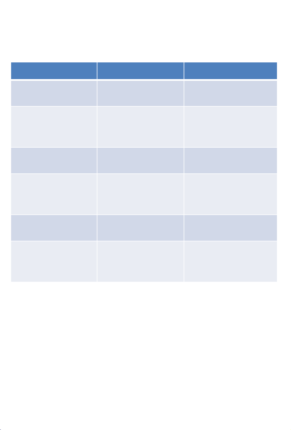
(1) CCU (Cockpit Control Unit)
Type Region Parts No.
BASE USA 86201AN60A
BASE CANADA
86201AN70A
&
MEXICO
MID USA 86201AN65A
MID CANADA
86201AN75A
&
MEXICO
HIGH USA 86271AN60A
HIGH CANADA
86271AN70A
&
MEXICO
Page 7
(2) CID (Center Information Display)
7
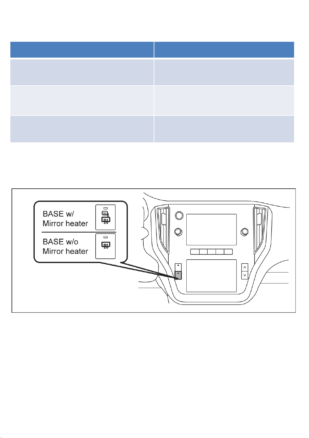
Type Parts No.
BASE w/ Mirror heater*
(Dual-7.0 inch)
BASE w/o Mirror heater*
(Dual-7.0 inch)
HIGH&MID
(11.6-inch)
*How to identify the BASE CID with or without mirror heater.
86213AN60A
86213AN61A
86213AN65A
Page 8
(3) Power Amplifier
8
MANUFACTURER Parts No.
Harman Kardon 86221AN01A
(4) Speakers
CCU Grade Speakers
BASE Front 2 Rear 2
MID Front 4 Rear 2
MID + Power Amplifier HK Front 6 Rear 4 + Woofer +
Center speaker
HIGH Front 4 Rear 2
HIGH + Power Amplifier HK Front 6 Rear 4 + Woofer +
Center speaker
Page 9
2. Product Outline
9
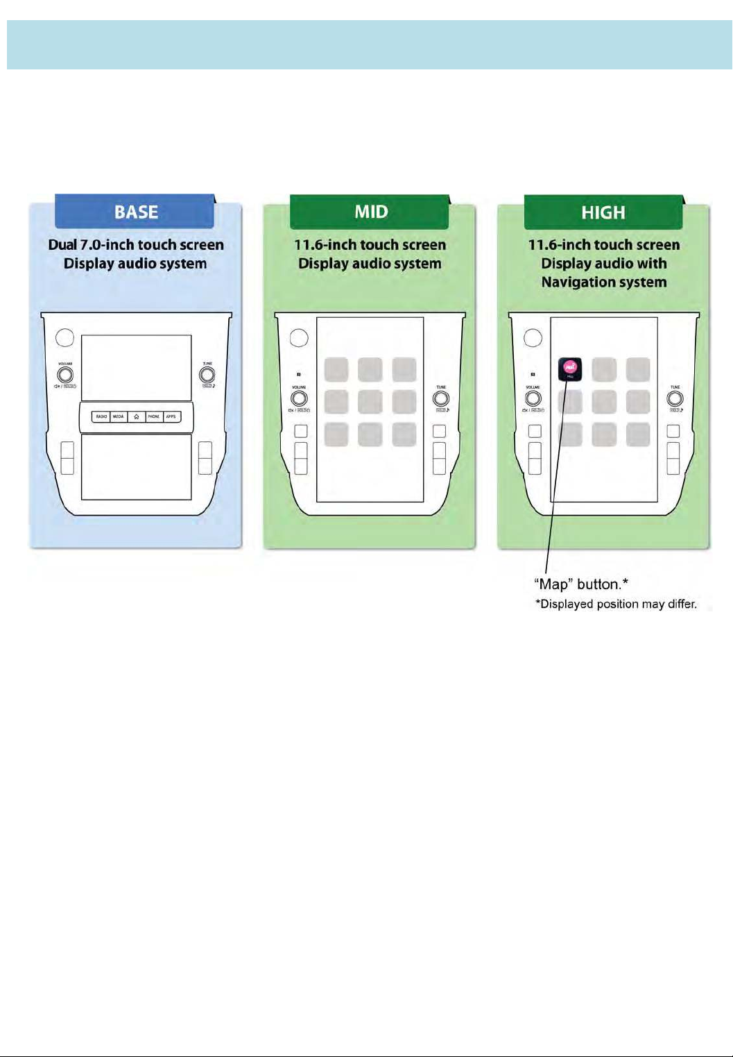
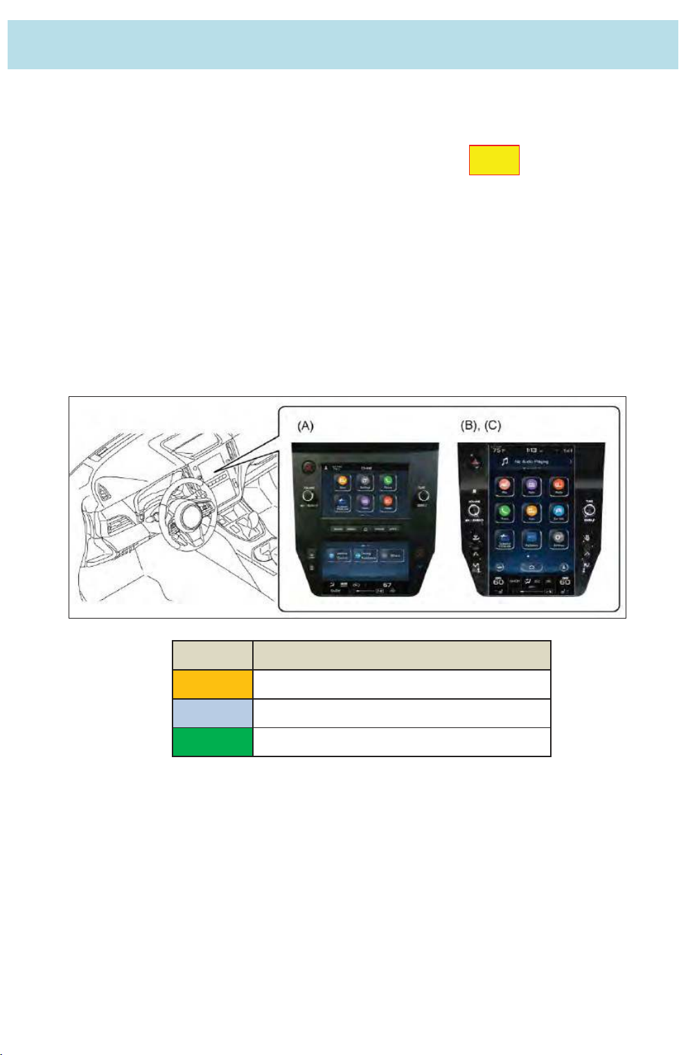
The Gen. 4.0 infotainment system has been adopted for the audio/navigation
system to enhance the following items.
- Three types of system settings: 7-inch dual display audio,
11.6-inch display audio and 11.6-inch display navigation
- High-performance hardware with enhanced functions
- Design that combines an advanced style with user-friendliness
- GUI based on use cases of users
- Compatibility with smartphone functions such as Apple CarPlay, Android Auto and
SmartDeviceLink
- Three types of system settings (by grade): 4-speaker, 6-speaker (standard system) and
Harman/Kardon® audio systems
New
No. Type
A Base + audio
B High grade audio
C Navi & High grade audio
Page 10
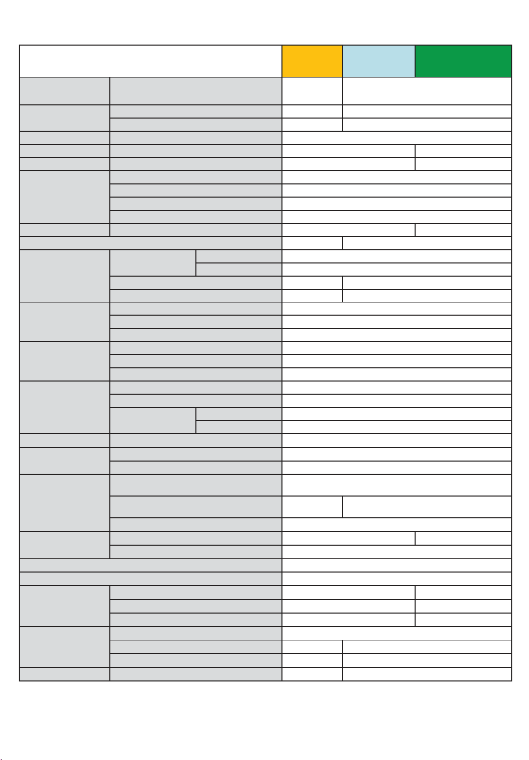
<Audio/Navigation Specification list >
10
㻌
Specification
㻌
㻌
Display Size/Resolution
Touch screen
㻌
Control Steering switch 8 buttons
Navi Navigation vender ӑ:Tom Tom
Traffic information SiriusXM
Radio tuner
Media slot Separate CD player (Option)
CDDB (Gracenote)
Connectivity (Wireless)
Connectivity (Wired)
Smartphone link
Server Service
SiriusXM Travel Link Weather, Fuel, Sports, Stocks
Voice control
Vehicle system control
Camera
Language/Display English (USA), French (Canadian), Spanish (Mexican)
Language/Voice recognition English (USA), French (Canadian), Spanish (Mexican)
Map data update
Software update
Update Server Redbend
Capacitive/Multi touch ӑ (Top)
Resistive film touch ӑ (Bottom)
AM/FM
Radio Broadcast Data System(RBDS)
HD Radio (ver.1.5 dual tuner)
SiriusXM Satellite Radio
BT
Wi-Fi (2.4 GHz)
NFC
USB version and quantity
USB
USB audio (iPod/USB memory)
Apple CarPlay
Google Android Auto
SmartDeviceLink (SDL)
Aha (by Harman)
Pandora
SUBARU STARLINK
Head unit function all control
Air conditioning control
Combination meter
(Multi-information display (MID))
Data Communication Module
(DCM)
Air conditioner system
Front camera input (Option) ӑ (NTSC)
Rear camera input ӑ (NTSC)
Wired (USB memory) (Full update)
Wireless Wi-Fi (Incremental update)
Smartphone Apps (Incremental update)
Wired (USB memory)
Wireless Wi-Fi
Wireless Smartphone Tethering
Audio
Hands Free Control
Clarion Cloud Service
Smart Device Link(SDL)
Base+ audio High grad audio Navi & High grad audio
7 inch/WVGA
(Dual display)
11.6 inch/FHD((Full High Definition))
䕿
䕿
䕿
䕿
䕿
䕿
䕿
䕿
䕿
䕿
䕿
䕿
䕿
䕿
䕿
䕿
䕿
䕿
䕿
䕿
䕿
䕿
䕿
䕿
䕿
䕿
䕿
䕿
䕿
䕿
䕿
䕿
䕿
䕿
䕿
Page 11
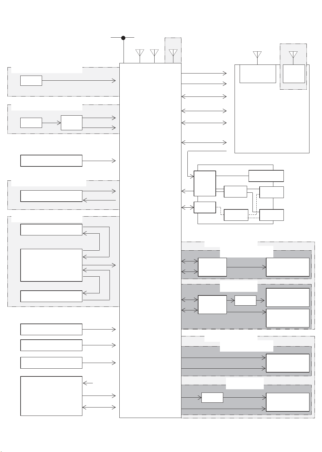
<System diagram>
11
HS-CAN
FM/AM
XM
NAVI only
GPS
11.6-inch
Wide Display only
WITHOUT DCM
MIC
WITH DCM
MIC
Steering switch
DCM
WITHOUT FRONT CAMERA
Rear View Camera
WITH FRONT CAMERA
Front View Camera
Analog
Analog(MIC)
MUTE
Command
Video
Power
Video
Power
Cockpit
Control
Unit
+B Back Up
IGN
CID Data
UART 2
BT Data
Wi-Fi Data
(11.6-inch Display)
ACC
External Input Terminal
W/H
4P
Bluetooth
ANT
Center Information Display
DCDC
HUB
Mini-Jack
USB
USB
Wi-Fi
ANT
Audio
Picture/
Movie/
Audio
Picture/
Movie/
Audio
Camera ECU
Rear View Camera
BATT (Back Up)
IGN/Acc
ILL/BRIGHT
CD/DVD DECK
Video
Power
Video
BATT
Deck V Bus
Deck D+,D-
Line out
CAN
Line out
CAN
Front
Rear
BRAND SPEAKER
AMP
(Brand)
WITH DCM
AMP
(Brand)
STD SPEAKER
Front
Rear
DCM
WITHOUT DCM
DCM
WITHOUT DCM
WITH DCM
Speaker
(Brand)
INP Speaker
(Brand)
Other Speaker
(Brand)
Speaker
(STD)
Speaker
(STD)
Page 12
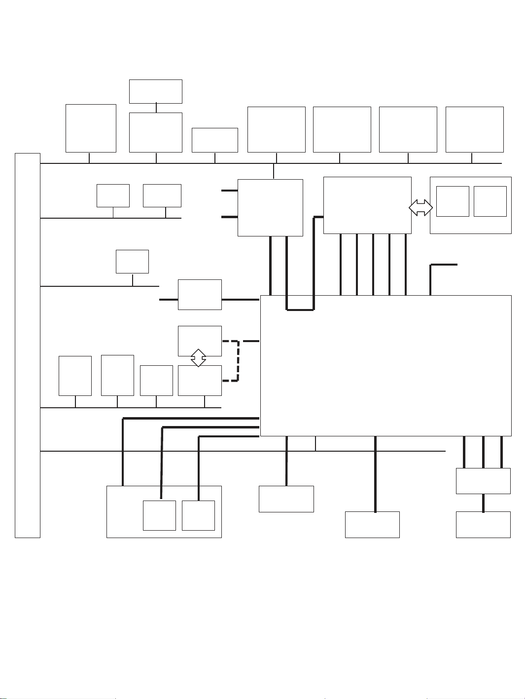
< System diagram : CAN communication>
12
Hazard
Central
Gateway
CU
Driver
Monitoring
Unit
Body
CAN
Chassis
CAN
Power Unit
CAN
Stereo
Camera
TPMS
CU
ECU
+B_backup
Radar
Sensor
LH
Body
Integration
Unit
VDC CU
RAB
CU
A/C CU
+B_
direct
IGN
CD
Rear
Camera
Camera
CU
LDVS
USB2.0
NTSC/
6.0V
Power
Rear gate
CU
Twin +
4.2inch TFT
Meter
UART
Power
Seat
CU
CID
(11.6inch)
LVDS
/RF
Wi-Fi
BT
Cockpit Control Unit
Outer
Mirror
CU LH
IGN
+B_backup
Headlamp
Automatic
Leveling LH
CID
(7inch)
+B_direct/
+B_backup
IGN/REV
With
CID
(7inch)
Advanced
Safety CAN
Outside
Connection
CAN
+B
AUX
Analog
Jack
Pin
USB2.0
USB
㽢2
Resistance
Division
Sterring
SW
Antenna
XM
RF RF +B
Antenna
AMP
Antenna
AM / FM
Page 13
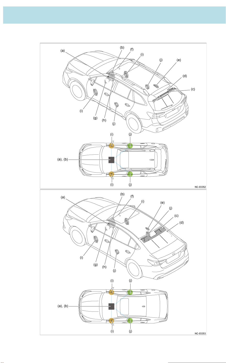
3. Location
13
3-1㻌 Standard audio system (4 - speaker)
䠄OUTBACK model/Sedan model, by grade䠅
Page 14

No. Parts name Function
14
(a)
(b)
(c)
(d)
(e)
(f)
(g)
(h)
Cockpit Control Unit
䠄CCU䠅
䠄Cockpit Gen.1.0
7-inch dual display audio䠅
Center information display䠄CID䠅
䠄Cockpit Gen.1.0
7-inch dual display audio䠅
Embedded Antenna
(Glass printed antenna)
(AM/FM Radio)
Antenna Amplifier
Roof Antenna
(SiriusXM radio)
Microphone
Steering switch
External Input Terminal
- Controls the Gen. 4.0 7-inch dual display audio and plays the audio of audio sources
such as AM/FM radio, SiriusXM radio and USB audio.
- Recognizes passenger voice commands input from the microphone to execute
operations.
- Outputs the voice signals from each audio source to the speakers.
- Displays the operation screen and status information screen of the selected audio
source.
- Equipped with a built-in Bluetooth module, which enables playback of audio files and
the use of hands-free functions when connected with a compatible device.
- The printed antenna located in the rear windshield receives AM/FM radio broadcast
waves.
Amplifies the AM/FM radio broadcast waves received by the radio antenna and
outputs the amplified waves to the head unit.
The fin type antenna located on the roof receives SiriusXM radio broadcast waves and
outputs the waves to the cockpit control unit.
Located in the map light, the microphone collects the sound of the passenger's voice
when using the voice recognition function or hands-free function.
Used to operate volume adjustment or switch between modes, and sends audio
operation signals such as station selection to the cockpit control unit.
- One AUX terminal and two USB terminals are provided as input terminals for external
devices.
- When a portable audio player is connected to the AUX terminal, the voice signal is
output to the cockpit control unit.
- When USB memory or a device such as an iPod or iPhone is connected to the USB
terminal, USB communication is performed with the cockpit control unit. The device
connected to the USB terminal can also be charged.
Front Door Speaker
(i)
Rear Door Speaker
(j)
Outputs the voice signals input from the cockpit control unit.
Page 15
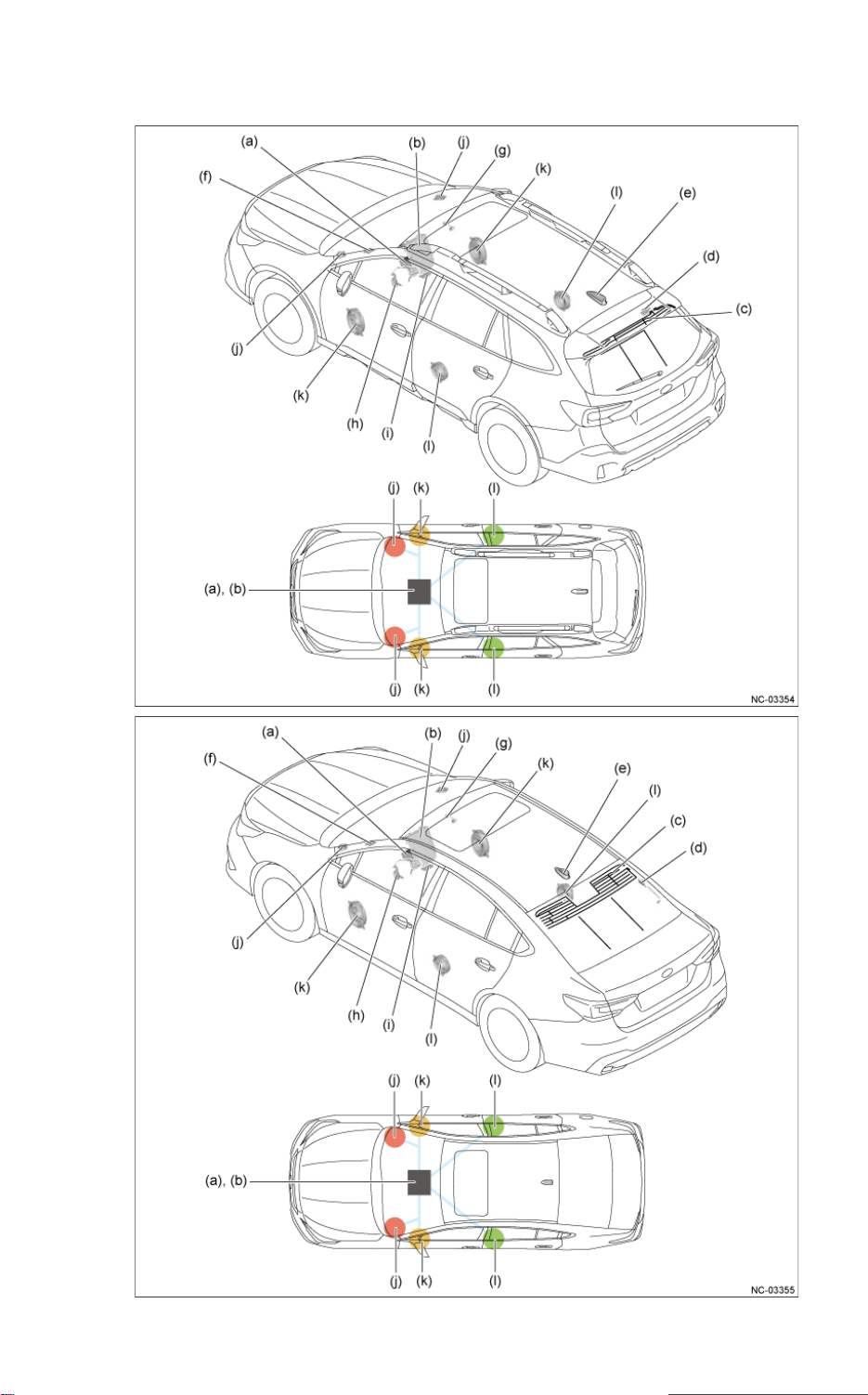
3-2 Standard audio / Navigation system (6 - speaker)
15
䠄OUTBACK model/Sedan model, by grade䠅
Page 16

No. Parts name Function
16
- Controls the Gen. 4.0 11.6-inch display audio or 11.6-inch display navigation and plays
(a)
Cockpit Control Unit
䠄CCU䠅
䠄Cockpit Gen.1.0.
11.6-inch display audio/
11.6-inch display navigation䠅
the audio of audio sources such as AM/FM radio, SiriusXM radio and USB audio.
- Recognizes passenger voice commands input from the microphone to execute
operations.
- Outputs the voice signals from each audio source to the speakers.
- Equipped with a navigation computer, which calculates the current location based on
data such as information received from the navigation antenna and plots the current
location screen.
(b)
(c)
(d)
(e)
(f)
(g)
(h)
(i)
Center information display
䠄CID䠅
䠄Cockpit Gen.1.0.
11.6-inch display audio/
11.6-inch display navigation䠅
Embedded Antenna
(Glass printed antenna)
(AM/FM Radio)
Antenna Amplifier
Roof Antenna
(SiriusXM radio)
GPS Antenna
Antenna Amplifier
Steering switch
External Input Terminal
- Displays the operation screen and status information screen of the selected audio
source.
- Equipped with a built-in Bluetooth module, which enables playback of audio files and
the use of hands-free functions when connected with a compatible device.
- Displays the navigation screen plotted by the cockpit control unit.
- The printed antenna located in the rear windshield receives AM/FM radio broadcast
waves.
Amplifies the AM/FM radio broadcast waves received by the radio antenna and
outputs the amplified waves to the head unit.
The fin type antenna located on the roof receives SiriusXM radio broadcast waves and
outputs the waves to the cockpit control unit.
Receives orbital signals from a satellite orbiting the Earth at an altitude of
approximately 20,000 km and sends the signals to the navigation computer in the
cockpit control unit.
Amplifies the AM/FM radio broadcast waves received by the radio antenna and
outputs the amplified waves to the head unit.
Used to operate volume adjustment or switch between modes, and sends audio
operation signals such as station selection to the cockpit control unit.
- One AUX terminal and two USB terminals are provided as input terminals for external
devices.
- When a portable audio player is connected to the AUX terminal, the voice signal is
output to the cockpit control unit.
- When USB memory or a device such as an iPod or iPhone is connected to the USB
terminal, USB communication is performed with the cockpit control unit. The device
connected to the USB terminal can also be charged.
(j)
(k)
(l)
Instrument Panel side speaker
Front Door Speaker
Rear Door Speaker
Outputs the voice signals input from the cockpit control unit
Page 17
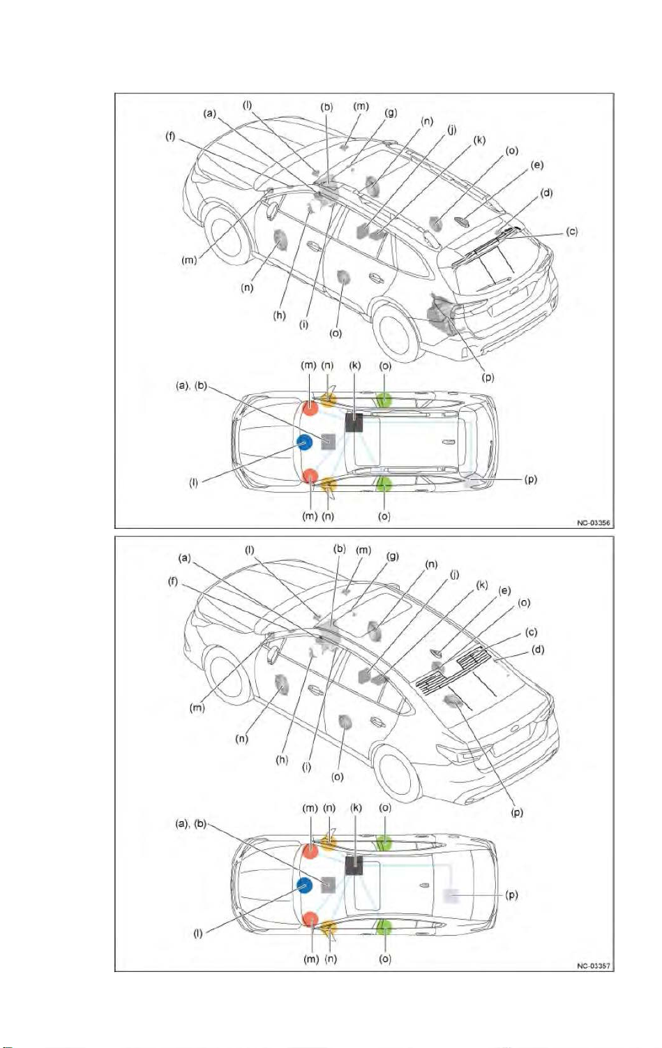
3-3㻌 Harman/Kardon® Audio / Navigation system
17
䠄OUTBACK model/Sedan model, by grade䠅
Page 18

No. Parts name Function
18
- Controls the Gen. 4.0 11.6-inch display audio or 11.6-inch display navigation and plays
Cockpit Control Unit
䠄CCU䠅
䠄Cockpit Gen.1.0.
(a)
11.6-inch display audio/
11.6-inch display navigation䠅
the audio of audio sources such as AM/FM radio, SiriusXM radio and USB audio.
- Recognizes passenger voice commands input from the microphone to execute
operations.
- Outputs the voice signals from each audio source to the power amplifier.
- Equipped with a navigation computer, which calculates the current location based on
data such as information received from the navigation antenna and plots the current
location screen.
(b)
(c)
(d)
(e)
(f)
(g)
(h)
(i)
Center information display䠄CID䠅
䠄Cockpit Gen.1.0.
11.6-inch display audio/
11.6-inch display navigation䠅
Embedded Antenna
(Glass printed antenna)
(AM/FM Radio)
Antenna Amplifier
Roof Antenna
(SiriusXM radio)
GPS Antenna
Antenna Amplifier
Steering switch
External Input Terminal
- Displays the operation screen and status information screen of the selected audio
source.
- Equipped with a built-in Bluetooth module, which enables playback of audio files and
the use of hands-free functions when connected with a compatible device.
- Displays the navigation screen plotted by the cockpit control unit.
- The printed antenna located in the rear windshield receives AM/FM radio broadcast
waves.
Amplifies the AM/FM radio broadcast waves received by the radio antenna and outputs
the amplified waves to the head unit.
The fin type antenna located on the roof receives SiriusXM radio broadcast waves and
outputs the waves to the cockpit control unit.
Receives orbital signals from a satellite orbiting the Earth at an altitude of approximately
20,000 km and sends the signals to the navigation computer in the cockpit control unit.
Amplifies the AM/FM radio broadcast waves received by the radio antenna and outputs
the amplified waves to the head unit.
Used to operate volume adjustment or switch between modes, and sends audio
operation signals such as station selection to the cockpit control unit.
- One AUX terminal and two USB terminals are provided as input terminals for external
devices.
- When a portable audio player is connected to the AUX terminal, the voice signal is
output to the cockpit control unit.
- When USB memory or a device such as an iPod or iPhone is connected to the USB
terminal, USB communication is performed with the cockpit control unit. The device
connected to the USB terminal can also be charged.
(j)
(k)
(l)
(m)
(n)
(o)
(p)
Disc player
( option )
Power amplifier Outputs the voice signals input from the power amplifier.
Instrument Panel center speaker
Instrument Panel side speaker
Front Door Speaker
Rear Door Speaker
Rear quarter speaker
( OUTBACK model subwoofer)
Rear shelf speaker
( Sedan model subwoofer )
Equipped with a built-in CD drive, and when a supported disc is inserted, sends the read
signals to the cockpit control unit.
Outputs the voice signals input from the power amplifier.
Page 19
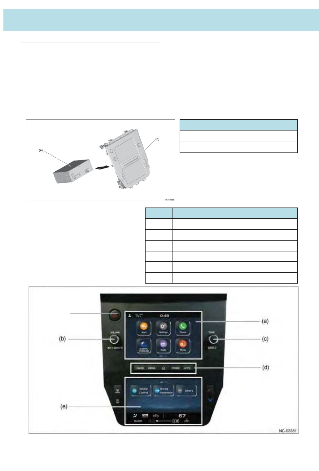
4. Product knowledge
19
4.1 Hardware constitution, Visual design
(1) 7-inch dual display Audio
An exterior has been adopted where 7-inch displays are positioned at the top and bottom of a
polycarbonate semi-gloss black coated panel, and a simple design is used that retains only
frequently used dial knobs and hard buttons.
The exterior gives the appearance of an advanced infotainment system, together with the GUI
enabling intuitive operations like a smartphone.
No. Parts Name
(f)
(a)
(b)
No. Button
(a) Capacitive touch operation display
(b) Dial switch (VOLUME)
(C) Dial switch (TUNE)
(d) Hard switch (Home screen display, source choice)
(e) Resistive touch operation display
(f) Hazard Warning flasher Switch
Cockpit Control Unit 䠄CCU䠅
Center information display 䠄CID䠅
Page 20
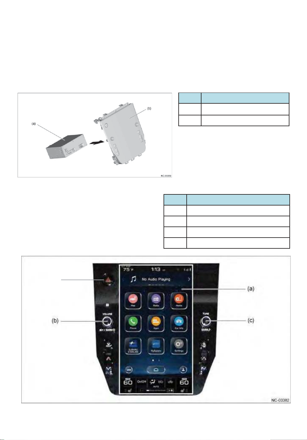
(2) 11.6-inch display audio/11.6-inch display navigation
20
An 11.6-inch display is embedded into a polycarbonate in-mold formed black panel to achieve
a seamless exterior, and a simple design is used that retains only frequently used dial knobs
and hard buttons.
No. Parts Name
(a)
Cockpit Control Unit 䠄CCU䠅
(b)
Center information display 䠄CID䠅
No. Button
(a) Capacitive touch operation display
(d)
(b) Dial switch (VOLUME)
(C) Dial switch (TUNE)
(d) Hazard Warning flasher Switch
Page 21
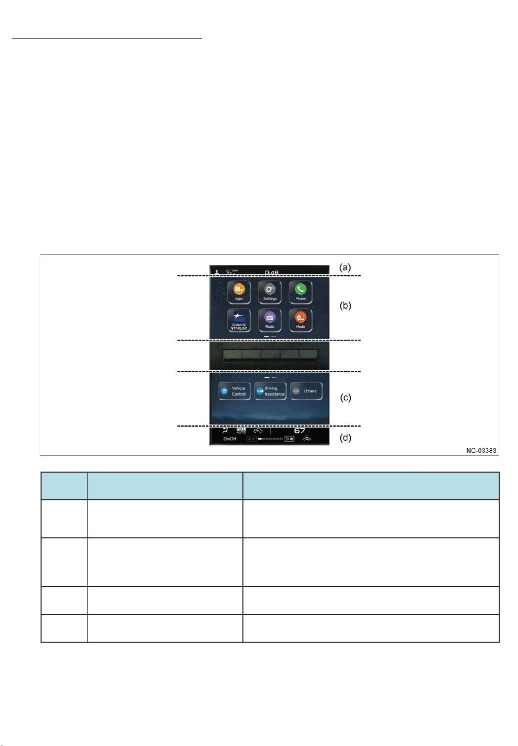
4.2 GUI ( Graphical User Interface )
21
(1) 7-inch dual display Audio
- A Home screen has been adopted that is categorized with icons designed to make it easy to
identify the portals for the main infotainment system functions.
- Supports touch operations such as drag and swipe.
- Some of the operation buttons for functions provided in the vehicle and the customization
menu are integrated into the switch operations on the screen.
- The status and operation panel for the air conditioner are displayed on the screen, and most
of the operation buttons are integrated into the switch operations on the screen.
- A display area has been set on the screen to enable display of various types of information
and operation of functions simultaneously with no loss of visibility.
No. The area name Contents
In addition to the driver profile button, displays the exterior air
(a)
(b)
(c)
(d)
Status bar area
Category area
Setting area
Operation area for the air conditioner
temperature, time and status icons (status of the Bluetoothconnected devices and volume mute, etc.).
- Displays the Home screen, and screens in other hierarchical levels,
for settings and operating and selecting the audio source and other
items.
- The main operations are performed in this area.
- Displays a settings screen for the air conditioner and other
functions provided in the vehicle.
Displays an operation screen and the status for the air㻌 conditioner.
Page 22
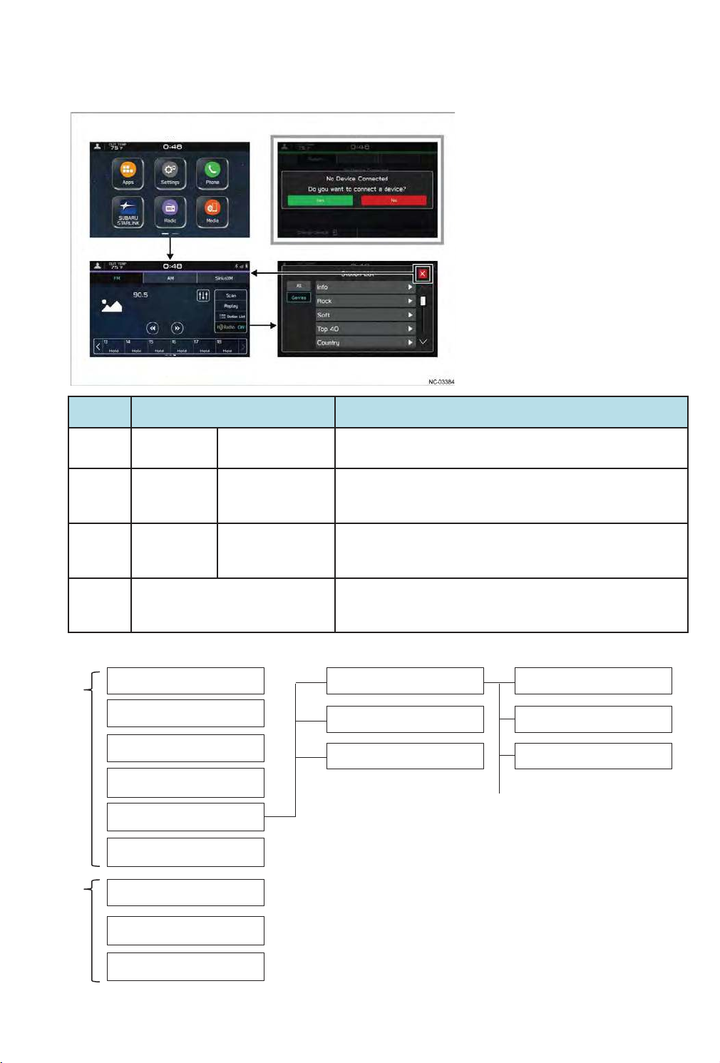
The screen displayed in the category area is comprised of a three-level hierarchical display and
22
a pop-up display, and the simple GUI designed for good visibility and operability provides
assistance for infotainment system operations.
(a)
(b)
(d)
(C)
No. Screen hierarchy Contents
(a)
(b)
(C)
First layer Home screen
Second layer Category screen
Third layer
Category(details)
Screen
Displays icons as portals for the main categories of the
infotainment system.
Provides the main screen for the category selected in the Home
screen, and displays setting items and other information in the
category.
- Displays details or other information for a setting item selected
in the category screen.
- Select "x" (Close) to return to the category screen.
Upper
screen
Lower
screen
(d)
Pop-up screen
First layer
Apps
Settings
Phone
SUBARU STARLINK
Radio
Media
Vehicle Control
Driving Assistance
Others
Superimposes a notification or inquiry from the infotainment
system on the corresponding level display according to the
operation content.
Second layer
FM
AM
SiriusXM
Third layer
Staion List
Page 23
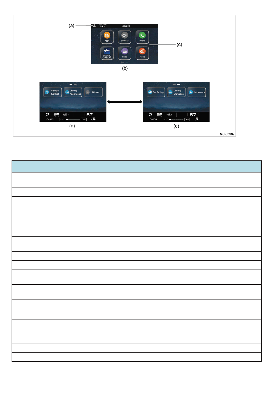
(a) Driver profile button (c) Home screen
23
(b) Upper screen (d) Lower screen
Icon name䠋Button name
Driver profile button Enables the display language and name of the infotainment system to be registered by
linking the system to a Bluetooth-connected mobile phone.
Radio
Media Enables the operation of an iPod, iPhone or USB device such as USB memory on which
Phone Enables Bluetooth connection operations for a mobile phone and operations for various
Apps Enables operations for the SUBARU STARLINK function, Travel Link function, Apple CarPlay
SUBARU STARLINK Enables operations for the SUBARU STARLINK function.
Settings Enables operation of setting items for the infotainment system.
Add to Shortcuts Enables the addition or deletion of a shortcut icon for the selected function to the Home
Vehicle Control - Enables operation of setting items for vehicle equipment categorized as Vehicle Control.
Driving Assistance - Enables operation of setting items for vehicle equipment categorized as Driving
Enables operations for the AM/FM radio function and SiriusXM radio function.FM
music files are recorded that is connected to the USB terminal, the operation of a device on
which music files are recorded that is connected via Bluetooth, and audio output operations
of a portable audio player connected to the AUX terminal.
hands-free functions.
function and Android Auto function.
screen.
- This can be operated even while driving.
Assistance.
- This can be operated even while driving.
Contents
Other - Enables operation of setting items for vehicle equipment categorized as Other.
- This can be operated even while driving.
Car Settings Enables operation of customization items for various functions provided in the vehicle.
Driving Statistics - Displays the operation status of Vehicle Dynamics Control (VDC) and vehicle body posture.
Maintenance - Enables operations for the maintenance function.
Page 24
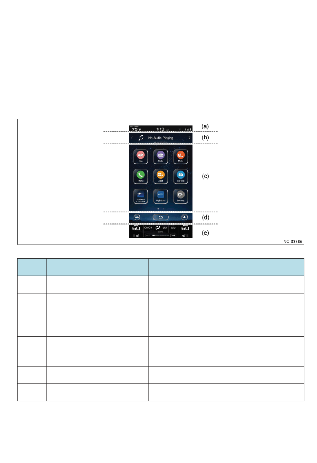
(2) 11.6-inch display audio / 11.6-inch display navigation
24
- A Home screen has been adopted that is categorized with icons designed to make it easy to identify the
portals for the main infotainment system functions.
- Supports touch operations such as drag and swipe.
- Some of the operation buttons for functions provided in the vehicle and the customization menu are
integrated into the switch operations on the screen.
- The status and operation panel for the air conditioner are displayed on the screen, and most of the
operation buttons are integrated into the switch operations on the screen.
- A display area has been set on the screen to enable display of various types of information and operation
of functions simultaneously with no loss of visibility.
No. The area name Contents
(a)
(b)
(c)
(d)
(e)
Status bar area
Informaiton bar area
Category area
Home button area
Operation area for the air conditioner
Displays the exterior air temperature, time and status icons (status
of the Bluetooth-connected devices and volume mute, etc.).
- Displays the simple status of the selected audio source, the
weather forecast, turn-by-turn navigation (11.6-inch display
navigation only), Favorite Widgets and frequently used functions.
In addition, shows interrupt displays for information such as
notification when processing for the requested operation is
completed, and notifications from the infotainment system.
Displays the Home screen, screens in other hierarchical levels, for
settings and, operating and selecting the audio source and other
items, and the settings screen for the functions provided in the
vehicle.
Always displays the Home button, vehicle setting shortcut button
and driver profile button.
Displays the operation screen and status information screen of the
air conditioner.
Page 25
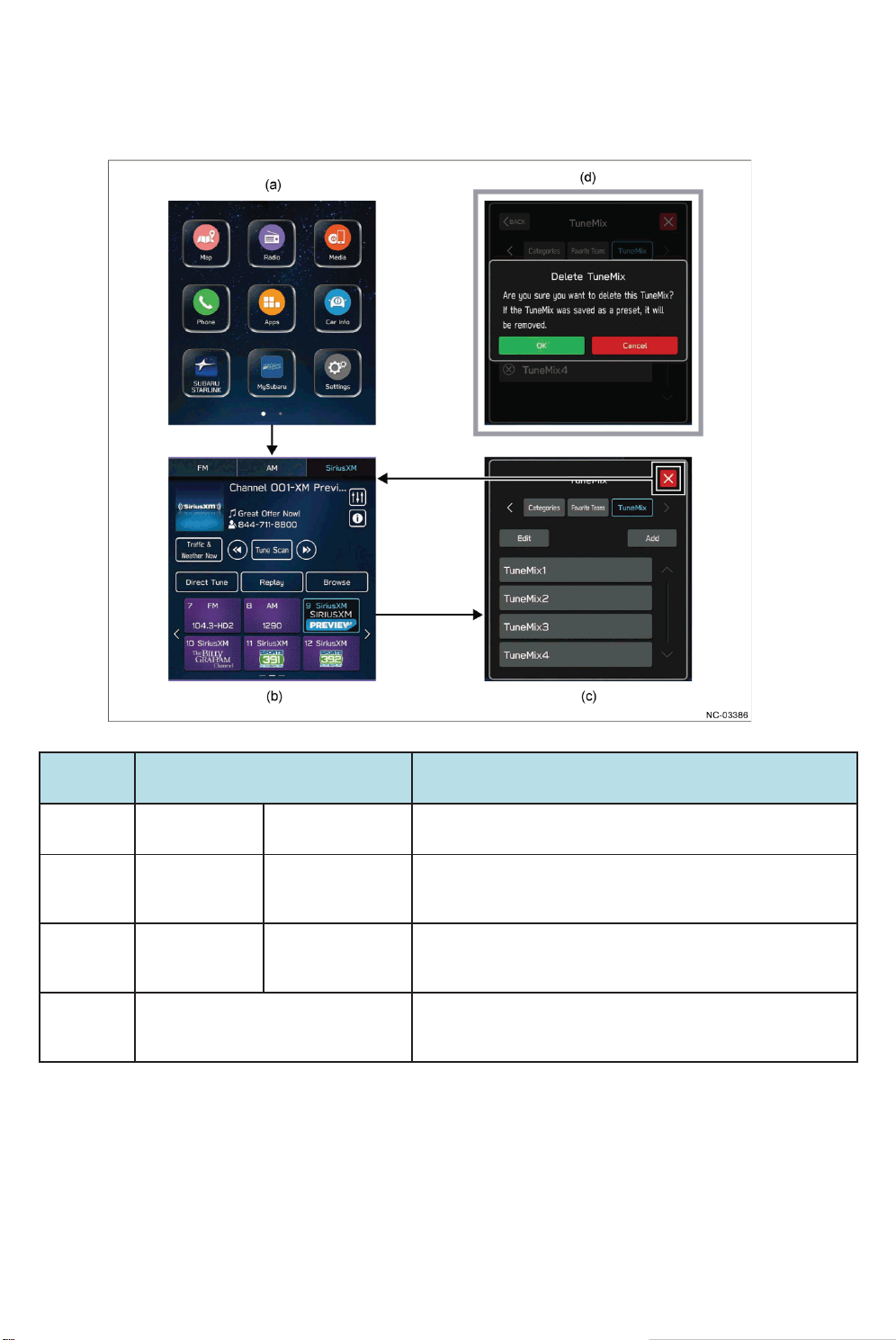
The screen displayed in the category area is comprised of a three-level hierarchical display
25
and a pop-up display, and the simple GUI designed for good visibility and operability
provides assistance for infotainment system operations.
No. Screen hierarchy Contents
(a)
(b)
(C)
(d)
First layer Home screen
Second layer Category screen
Third layer
Pop-up screen
Category(details)
Screen
Displays icons as portals for the main categories of the
infotainment system.
Provides the main screen for the category selected in the Home
screen, and displays setting items and other information in the
category.
- Displays details or other information for a setting item selected
in the category screen.
- Select "x" (Close) to return to the category screen.
Superimposes a notification or inquiry from the infotainment
system on the corresponding level display according to the
operation content.
Page 26
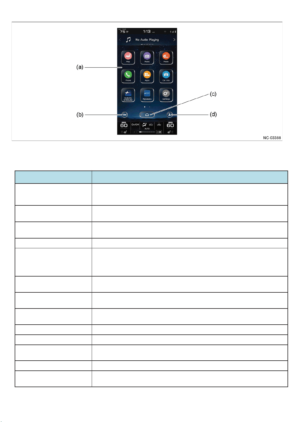
(a) Home screen (c) Home button
26
(b) Vehicle setting shortcut button (d) Driver profile button
Icon name䠋Button name
Vehicle setting shortcut button - Enables operation of setting items for vehicle equipment categorized in the tabs of Vehicle
Control, Driving Assistance and Other.
- This can be operated even while driving.
Home button Enables the display of the Home screen. When the Home button is touched, the screen
transitions to the Home screen regardless of the displayed contents of the category screen.
Driver profile button Enables the display language and name of the infotainment system to be registered by
linking the system to a Bluetooth-connected mobile phone.
Radio
Media Enables the operation of an iPod, iPhone or USB device such as USB memory on which
Phone Enables Bluetooth connection operations for a mobile phone and operations for various
Map䠄11.6-inch display audio and
navigation䠅
Apps Enables operations for the SUBARU STARLINK function, Travel Link function, Apple CarPlay
SUBARU STARLINK Enables operations for the SUBARU STARLINK function.
My Subaru Enables operations for the My Subaru function.
Enables operations for the AM/FM radio function and SiriusXM radio function.FM
music files are recorded that is connected to the USB terminal, the operation of a device on
which music files are recorded that is connected via Bluetooth, and audio output operations
of a portable audio player connected to the AUX terminal.
hands-free functions.
Enables the display of the map screen and the operation of the navigation function.
function and Android Auto function.
Contents
Car Info Enables the display or operation of information screens categorized in the tabs of Driving
Statistics, Advanced Package and Maintenance.
Settings Enables operation of setting items for the infotainment system.
Add to Shortcuts Enables the addition or deletion of a shortcut icon for the selected function to the Home
screen.
Page 27
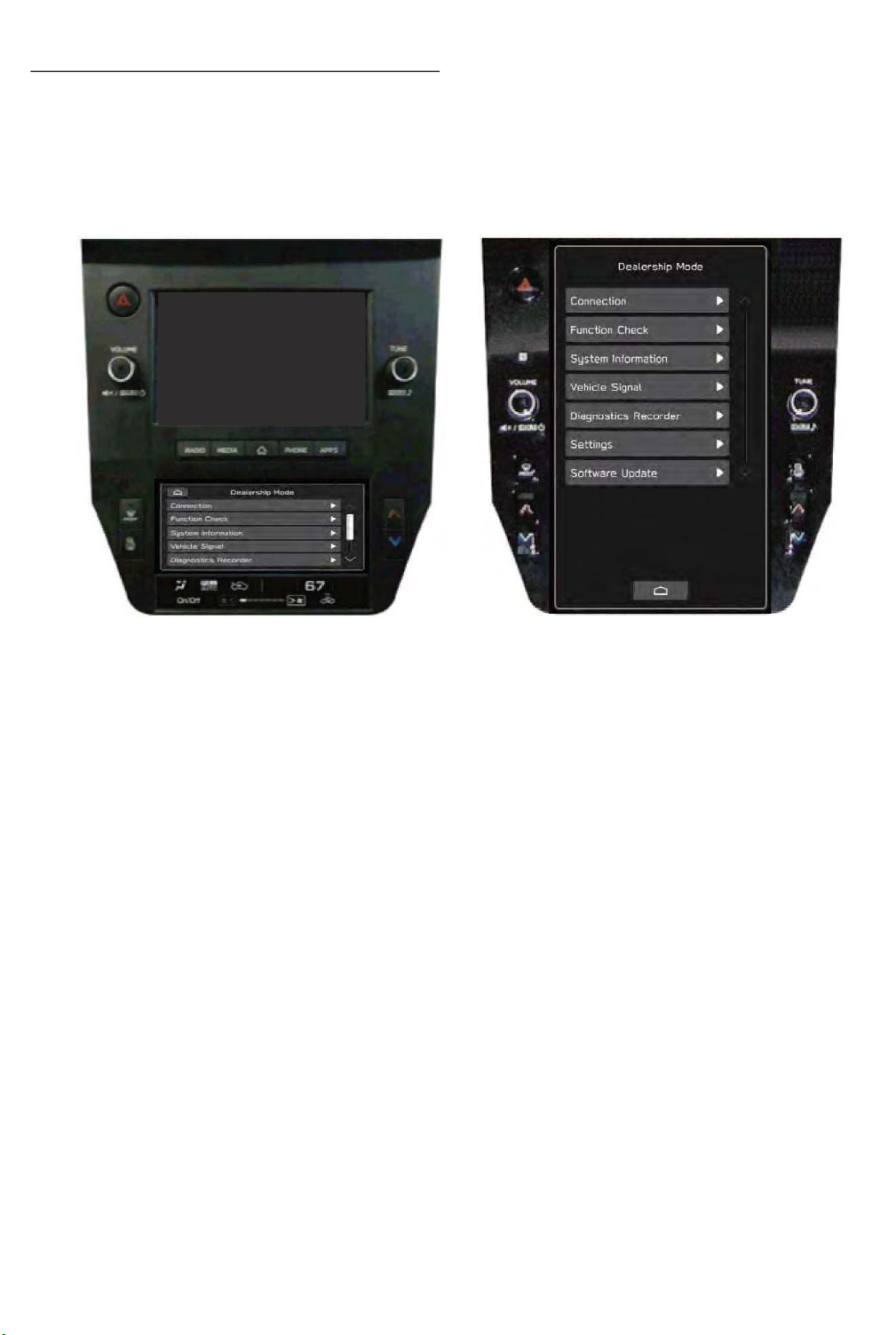
4.3 Self-check function (Dealership mode)
27
The infotainment system has a self-check function (dealership mode) which can be performed
on the screen. The function enables functions including checking the system operation status,
displaying the system status, and checking system information.
Page 28
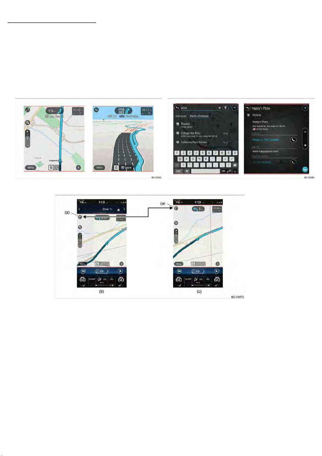
4.4 Function ( Icon menu )
28
(1) Navigation (11.6-inch display navigation )
The navigation screen is displayed in the category area.
Provided various map displays and information lists with better overview, making full use of
a large display area.
The zoom icon on the navigation screen can be selected to enlarge the display area of the
navigation screen over the information bar area.
(a) Zoom up/ Zoom out icon (c)Navigation screen enlarged display
䠄The information bar area non-display䠅
(b) Navigation screen normal display
䠄 The information bar area display 䠅
Page 29
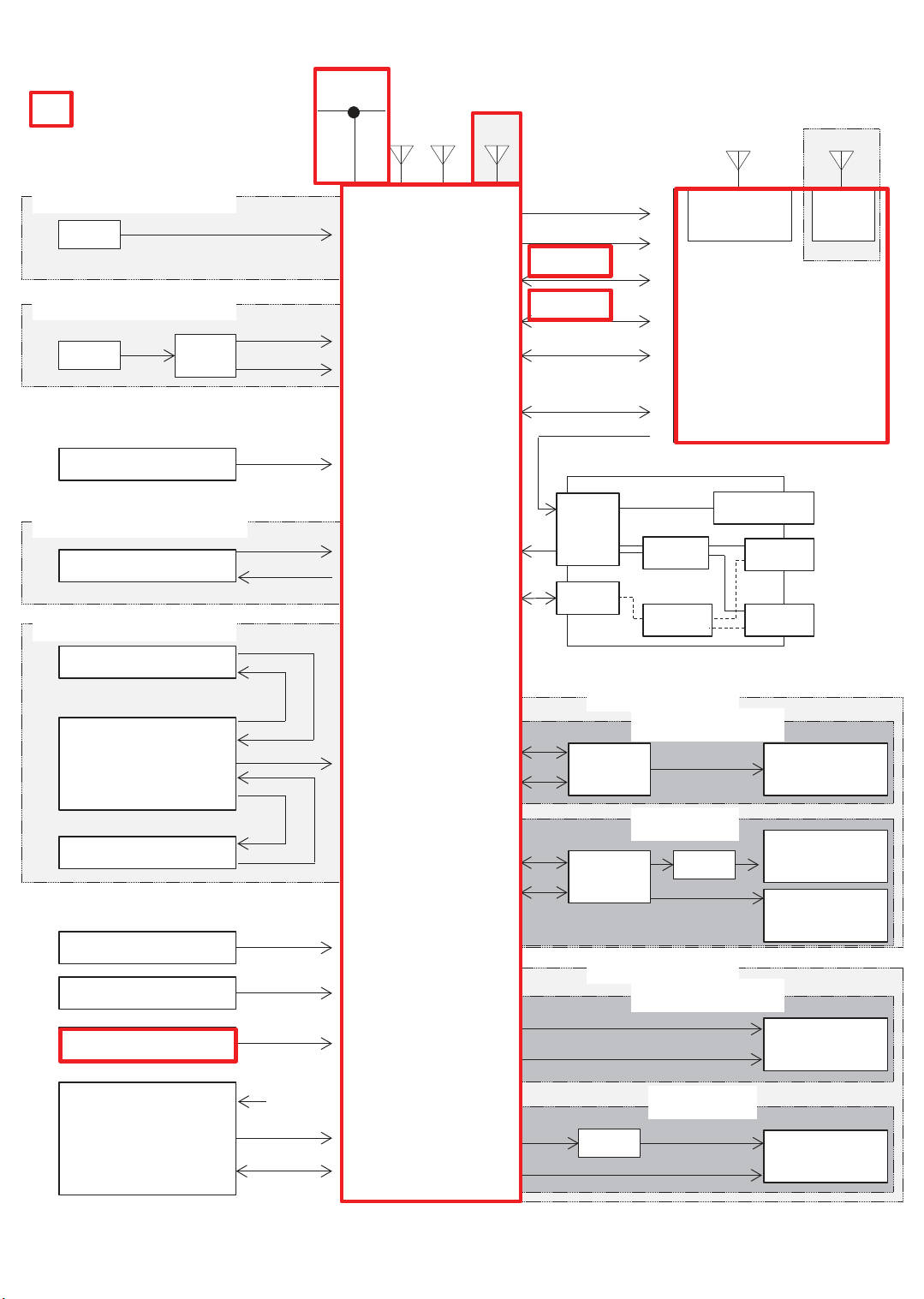
<System diagram>
29
Navigation-related㻌 signal,
and device
WITHOUT DCM
MIC
WITH DCM
MIC
Steering switch
DCM
WITHOUT FRONT CAMERA
Rear View Camera
WITH FRONT CAMERA
Front View Camera
Analog
Analog(MIC)
MUTE
Command
Video
Power
Video
Power
HS-CAN
FM/AM
XM
Cockpit
Control
Unit
NAVI only
GPS
+B Back Up
IGN
CID Data
CID Data
UART 2
BT Data
Wi-Fi Data
(11.6-inch Display)
ACC
External Input Terminal
W/H
4P
DCDC
HUB
11.6-inch
Wide Display only
Bluetooth
ANT
Center Information Display
Mini-Jack
Wi-Fi
ANT
Audio
Picture/
USB
Movie/
Audio
USB
Picture/
Movie/
Audio
Camera ECU
Rear View Camera
BATT (Back Up)
IGN/Acc
ILL/BRIGHT
CD/DVD DECK
Video
Power
Video
BATT
Deck V Bus
Deck D+,D-
Line out
CAN
Line out
CAN
Front
Rear
BRAND SPEAKER
AMP
(Brand)
AMP
(Brand)
STD SPEAKER
Front
Rear
DCM
WITHOUT DCM
WITH DCM
DCM
WITHOUT DCM
WITH DCM
Speaker
(Brand)
INP Speaker
(Brand)
Other Speaker
(Brand)
Speaker
(STD)
Speaker
(STD)
Page 30
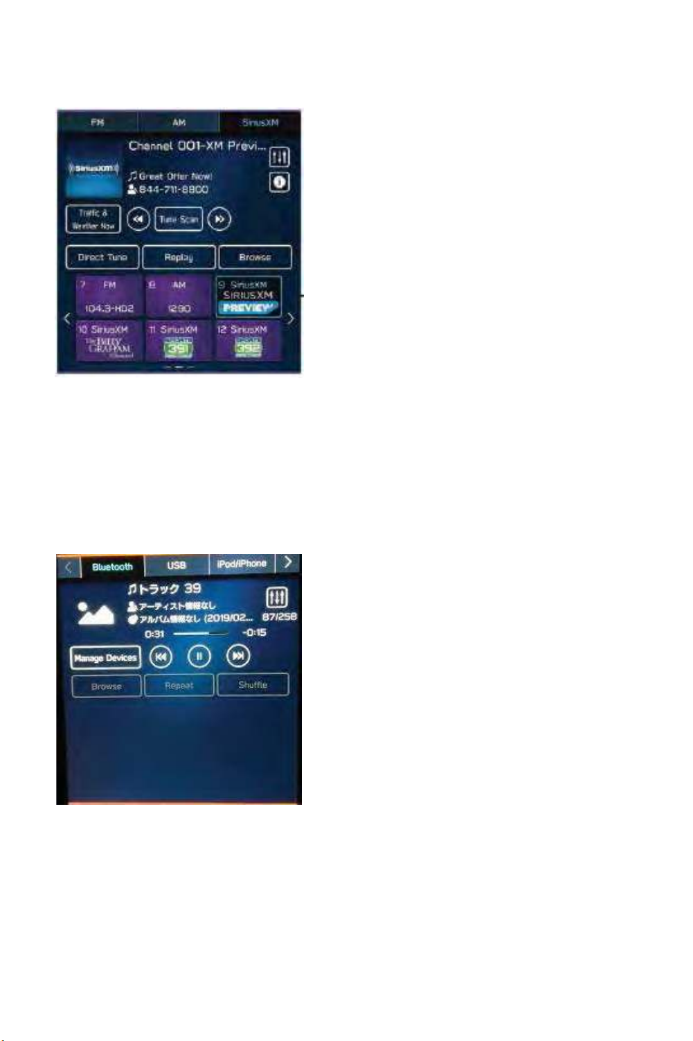
(2) Radio
30
Enables operations for the AM/FM radio function and SiriusXM radio function.FM
(3) Media
Enables the operation of an iPod, iPhone or USB device such as USB memory on which music
files are recorded that is connected to the USB terminal, the operation of a device on which
music files are recorded that is connected via Bluetooth, and audio output operations of a
portable audio player connected to the AUX terminal.
Page 31
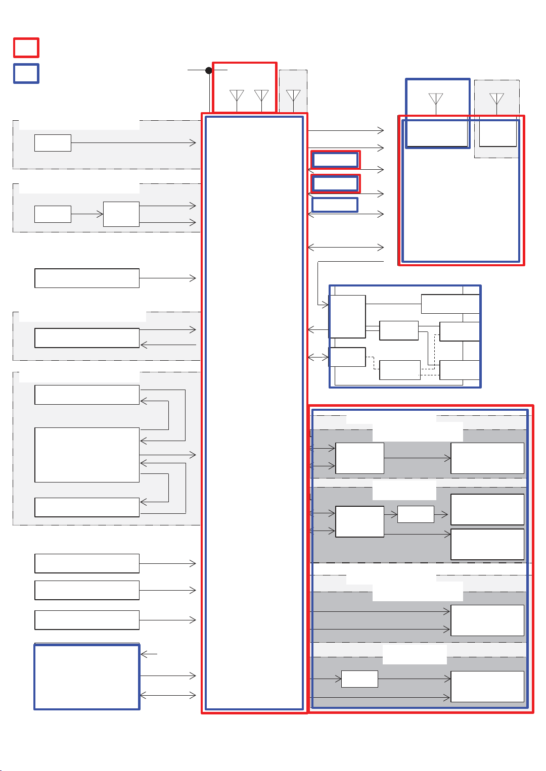
<System diagram>
31
Radio-related㻌 signal,and device
Media-related㻌 signal,and device
WITHOUT DCM
MIC
WITH DCM
MIC
Steering switch
DCM
WITHOUT FRONT CAMERA
Rear View Camera
WITH FRONT CAMERA
Front View Camera
Analog
Analog(MIC)
MUTE
Command
Video
Power
Video
Power
HS-CAN
FM/AM
XM
Cockpit
Contorol
Unit
NAVI only
GPS
+B Back Up
IGN
CID Data
UART 2
BT Data
Wi-Fi Data
(11.6-inch Display)
ACC
External Input Terminal
W/H
4P
DCDC
HUB
11.6-inch
Wide Display only
Bluetooth
ANT
Center Information Display
Mini-Jack
Wi-Fi
ANT
Audio
Picture/
USB
Movie/
Audio
USB
Picture/
Movie/
Audio
Camera ECU
Rear View Camera
BATT (Back Up)
IGN/Acc
ILL/BRIGHT
CD/DVD DECK
Video
Power
Video
BATT
Deck V Bus
Deck D+,D-
Line out
CAN
Line out
CAN
Front
Rear
BRAND SPEAKER
AMP
(Brand)
AMP
(Brand)
STD SPEAKER
Front
Rear
DCM
WITHOUT DCM
WITH DCM
DCM
WITHOUT DCM
WITH DCM
Speaker
(Brand)
INP Speaker
(Brand)
Other Speaker
(Brand)
Speaker
(STD)
Speaker
(STD)
Page 32
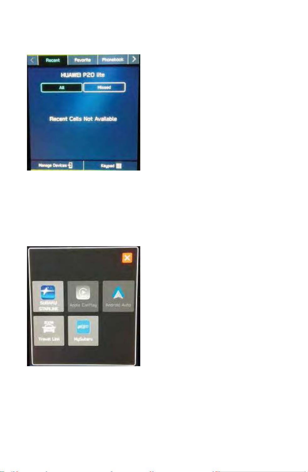
(4) Phone
32
Enables Bluetooth connection operations for a mobile phone and operations for various
hands-free functions.
(5) Apps
Enables operations for the SUBARU STARLINK function, Travel Link function, Apple CarPlay
function, My Subaru function and Android Auto function.
#Apple CarPlay
USB connection only ( lighting cable )
#Android Auto
㻌 USB connection, Bluetooth
Page 33
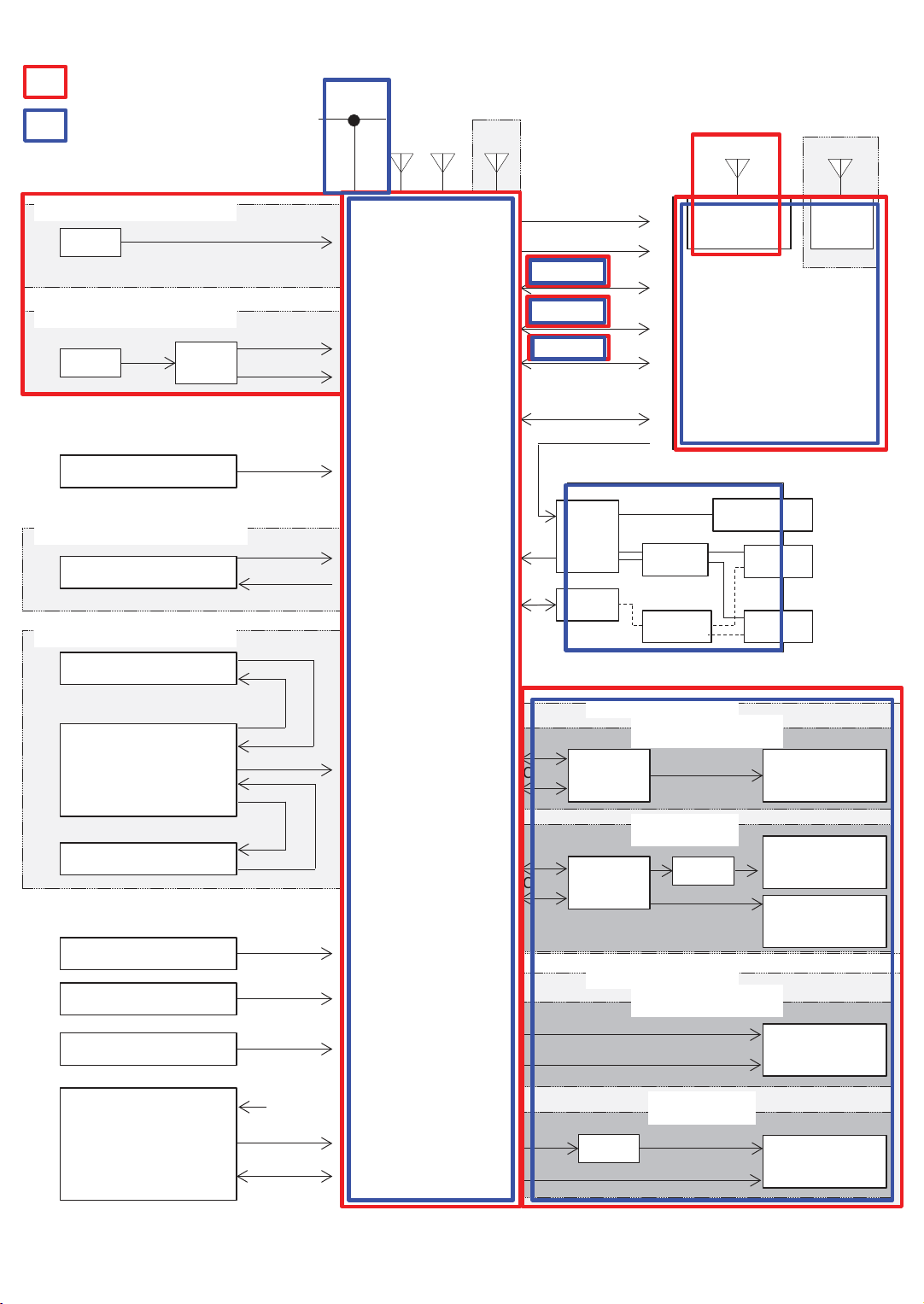
<System diagram>
33
Phone-related㻌 signal,and device
Apps-related㻌 signal,and device
WITHOUT DCM
WITHOUT DCM
MIC
WITH DCM
MIC
Steering switch
DCM
WITHOUT FRONT CAMERA
Rear View Camera
WITH FRONT CAMERA
Front View Camera
Analog
Analog(MIC)
MUTE
Command
Video
Power
Video
Power
HS-CAN
FM/AM
XM
Cockpit
Control
Unit
NAVI only
GPS
+B Back Up
IGN
CID Data
UART 2
BT Data
Wi-Fi Data
(11.6-inch Display)
ACC
External Input Terminal
W/H
4P
DCDC
HUB
11.6-inch
Wide Display only
Bluetooth
Bluetooth
ANT
ANT
Center Information Display
Mini-Jack
Wi-Fi
ANT
Audio
Picture/
USB
Movie/
Audio
USB
Picture/
Movie/
Audio
Camera ECU
Rear View Camera
BATT (Back Up)
IGN/Acc
ILL/BRIGHT
CD/DVD DECK
Video
Power
Video
BATT
Deck V Bus
Deck D+,D-
Line out
CAN
Line out
CAN
Front
Rear
Front
Rear
BRAND SPEAKER
WITHOUT DCM
AMP
(Brand)
WITH DCM
AMP
(Brand)
STD SPEAKER
WITHOUT DCM
WITH DCM
DCM
DCM
Speaker
(Brand)
INP Speaker
(Brand)
Other Speaker
(Brand)
Speaker
(STD)
Speaker
(STD)
Page 34
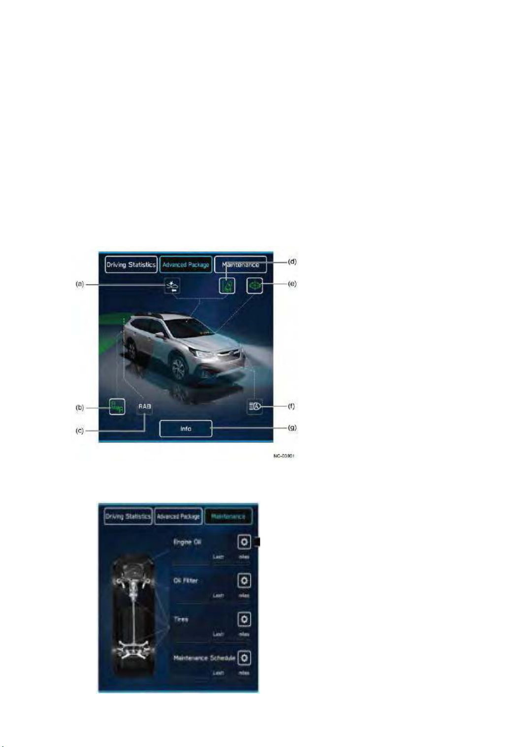
(6) Car Info ( 11.6-inch display only )
34
From this item, the user can set the display for the vehicle's onboard advanced safety
functions and the vehicle maintenance timing.
Enables the display or operation of information screens categorized in the tabs of Driving
Statistics, Advanced Package and Maintenance.
䙟 Advanced Package
This content displays a screen that presents a full visualization of SUBARU's advanced
safety functions. This enables the driver to provide a visual explanation to passengers
about the vehicle's onboard advanced safety functions.
Passengers can visually check the on/off status and operating status of normally invisible
functions, such as the EyeSight assist monitor, Reverse Automatic Braking (RAB),
automatic light, SUBARU Rear Vehicle Detection (SRVD) system, and so on.
Functions not equipped to the vehicle are not shown.
In addition, the illuminating condition of small lights, fog lights, high beams, brake lights,
and other lights can be checked from within the vehicle.
(a) Pre-collision braking system
(b) SUBARU Rear Vehicle Detection (SRVD) system
(c) Reverse Automatic Braking (RAB)
(d) Lane departure warning
(e) EyeSight assist monitor
(f) High beam assist
(g) Info button
䙟 Maintenance
The timing for changing engine oil, oil filter, and tires (by date/distance) and periodic inspections
(by date/distance) can be set up as follows.
Page 35
(7) SUBARU STARLINK
35
Enables operations for the SUBARU STARLINK function.
(8) MY㻌 SUBARU
Enables operations for the My Subaru function.
(9) Add to㻌 Shortcuts
Enables the addition or deletion of a shortcut icon for the selected function to the Home screen.
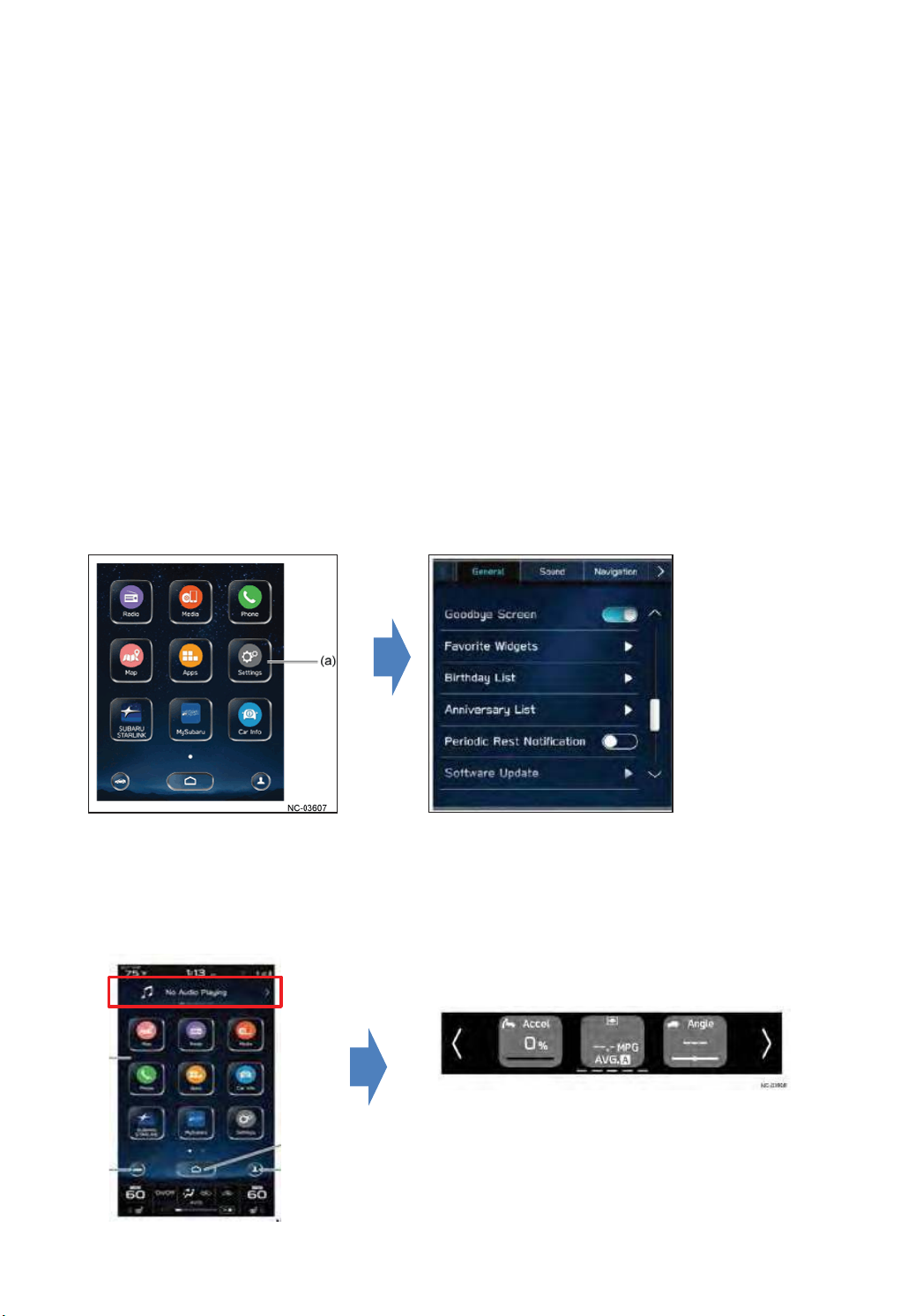
(10) Settings㻌 ( Infotainment system settings )
Touching the "Settings" button on the Home screen displays the settings items for the infotainment
system. The items are categorized into separate tabs according to function.
㻨㻻㼜㼑㼞㼍㼠㼕㼛㼚㻌㼑㼤㼍㼙㼜㼘㼑㻪㻌
㻌 㻲㼍㼢㼛㼞㼕㼠㼑㻌 㼃㼕㼐㼓㼑㼠㼟㻌㻔㻌㻝㻝㻚㻢㻙㼕㼚㼏㼔㻌㼐㼕㼟㼜㼘㼍㼥㻌㼛㼚㼘㼥㻌㻕㻌
㻌㼃㼕㼠㼔㻌㼠㼔㼕㼟㻌㼒㼡㼚㼏㼠㼕㼛㼚㻘㻌㼠㼔㼑㻌㼡㼟㼑㼞㻌㼏㼍㼚㻌㼟㼑㼘㼑㼏㼠㻌㼠㼔㼞㼑㼑㻌㼒㼍㼢㼛㼞㼕㼠㼑㼟㻌㼒㼞㼛㼙㻌㼍㼢㼍㼕㼘㼍㼎㼘㼑㻌㼏㼛㼚㼠㼑㼚㼠㻌㼠㼛㻌㼐㼕㼟㼜㼘㼍㼥㻌㼕㼚㻌㼠㼔㼑㻌
㼕㼚㼒㼛㼞㼙㼍㼠㼕㼛㼚㻌㼎㼍㼞㻌㼍㼞㼑㼍㻚㻌
㼀㼔㼑㻌㼒㼍㼢㼛㼞㼕㼠㼑㼟㻌㼍㼞㼑㻌㼟㼑㼘㼑㼏㼠㼑㼐㻌㼢㼕㼍㻌㼠㼔㼑㻌㻿㼑㼠㼠㼕㼚㼓㼟㻌㼕㼠㼑㼙㻌㼕㼚㻌㼠㼔㼑㻌㼏㼑㼚㼠㼑㼞㻌㼕㼚㼒㼛㼞㼙㼍㼠㼕㼛㼚㻌㼐㼕㼟㼜㼘㼍㼥㻚㻌
There are 11 types of content from which to choose.
- Water Temp. - Oil temp.
- Avg. Speed - Accelerator position
- Angle - Compass
- Weather - Speed limit
- Calendar - Fuel Cos.
- OFF
Page 36
(10)-1. 7-inch dual display Audio
36
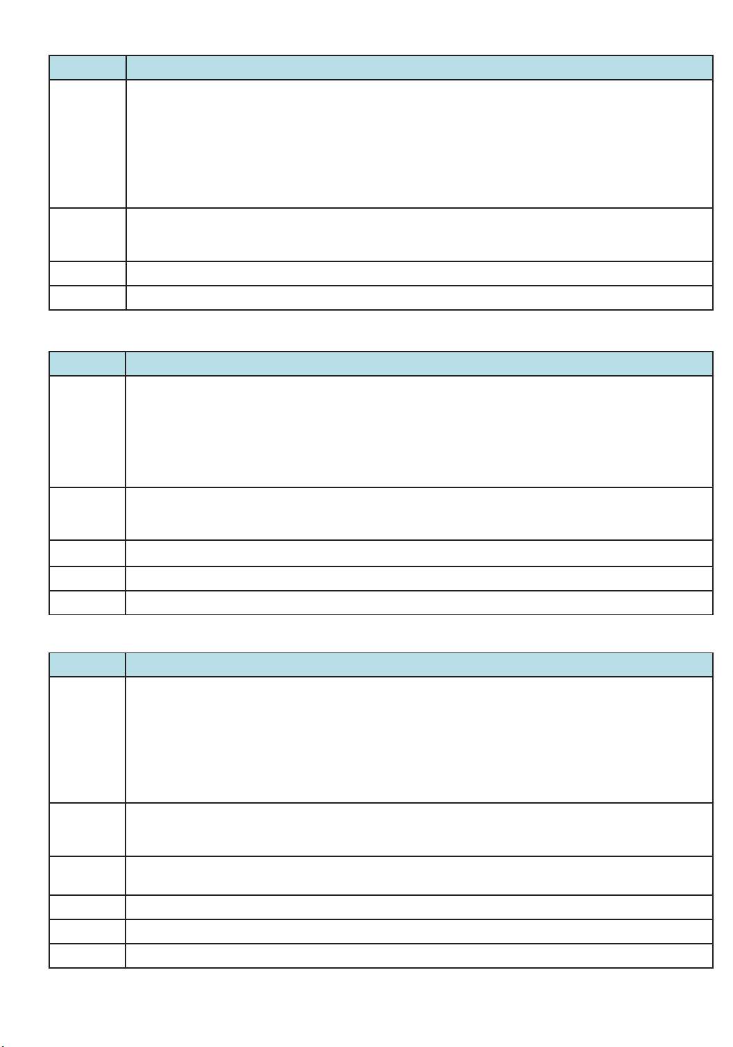
Tab Settings
General
Sound
Phone
Radio - Enables the setting of FM/AM radio and SiriusXM.
- Enables the setting of Clock䚸Display䚸Reminder Screen䚸Meter Screen䚸Camera䚸Climate Control䚸Language䚸Tire
Pressure Units䚸Home Screen Shortcuts䚸Welcome Screen䚸Goodbye Screen䚸Birthday List䚸Anniversary List䚸
STARLINK Apps Recovery䚸STARLINK Auto Connect.
(Some items may not be displayed depending on whether optional equipment is installed.)
- Enables the operation of Factory Data Reset.
- Enables the display of System Information and Free/Open Source Software Information for the infotainment
system.
- Enables the setting of Connect Phone, Phonebook/Recent Calls, Message, Apple CarPlay and Android Auto.
- Enables the setting of Audio䚸Notification Volume䚸Beep Sound Setting䚸Beep Sound Volume䚸Phone Ringtone
Volume䚸Incoming Call Volume䚸Call Volume䚸 SMS/MMS Ringtone Volume䚸SMS/MMS Read Out Volume䚸Voice
Volume .
- Enables the setting of Connect Phone䚸Phonebook/Recent Calls䚸Message䚸Apple CarPlay䚸Android Auto .
(10)-2. 11.6-inch display audio
Tab Settings
General
- Enables the setting of Clock䚸Display䚸Wi-Fi䚸Wi-Fi Hotspot䚸Reminder Screen䚸Meter Screen䚸Camera䚸Climate
Control䚸Language䚸Tire Pressure Units䚸Home Screen Shortcuts䚸Welcome Screen䚸Goodbye Screen䚸Birthday
List䚸Anniversary List䚸SoftwareUpdate䚸STARLINK Apps Recovery䚸STARLINK Auto Connect .
(Some items may not be displayed depending on whether optional equipment is installed.)
- Enables the operation of Factory Data Reset.
- Enables the display of System Information and Free/Open Source Software Information for the infotainment
system.
Sound
Phone
Radio - Enables the setting of FM/AM radio and SiriusXM.
Car - Enables operation of customization items for various functions provided in the vehicle.
- Enables the setting of Audio䚸Notification Volume䚸Beep Sound Setting䚸Beep Sound Volume䚸Phone Ringtone
Volume䚸Incoming Call Volume䚸Call Volume䚸 SMS/MMS Ringtone Volume䚸SMS/MMS Read Out Volume䚸Voice
Volume .
- Enables the setting of Connect Phone䚸Phonebook/Recent Calls䚸Message䚸Apple CarPlay䚸Android Auto .
(10)-3. 11.6-inch display navigation
Tab Settings
General
Sound
Navigation
- Enables the setting of Clock䚸Display䚸Wi-Fi䚸Wi-Fi Hotspot䚸Reminder Screen䚸Meter Screen䚸Camera䚸Climate
Control䚸Language䚸Tire Pressure Units䚸Home Screen Shortcuts䚸Welcome Screen䚸Goodbye Screen䚸Birthday
List䚸Anniversary List䚸Periodic Rest Notification䚸Software Update䚸STARLINK Apps Recovery䚸STARLINK Auto㻌
Connect .
(Some items may not be displayed depending on whether optional equipment is installed.)
- Enables the operation of Factory Data Reset.
- Enables the display of System Information and Free/Open Source Software Information for the infotainment
system.
- Enables the setting of Audio䚸Navigation Guidance Volume䚸Beep Sound Setting䚸Beep Sound Volume䚸Phone
Ringtone Volume䚸Incoming Call Volume䚸Call Volume䚸 SMS/MMS Ringtone Volume䚸 SMS/MMS Read Out
Volume䚸Voice Volume.
- Enables the setting of Show Along Route䚸Arrival Distance/Time䚸Freeway Exit Preview䚸Automatic Zoom䚸AutoHide Route Bar䚸Route Preference䚸Avoid䚸Traffic Warning Tone䚸Map Update .
Phone - Enables the setting of Connect Phone, Phonebook/Recent Calls, Message, Apple CarPlay and Android Auto.
Radio - Enables the setting of FM/AM radio and SiriusXM.
Car - Enables operation of customization items for various functions provided in the vehicle.
Page 37
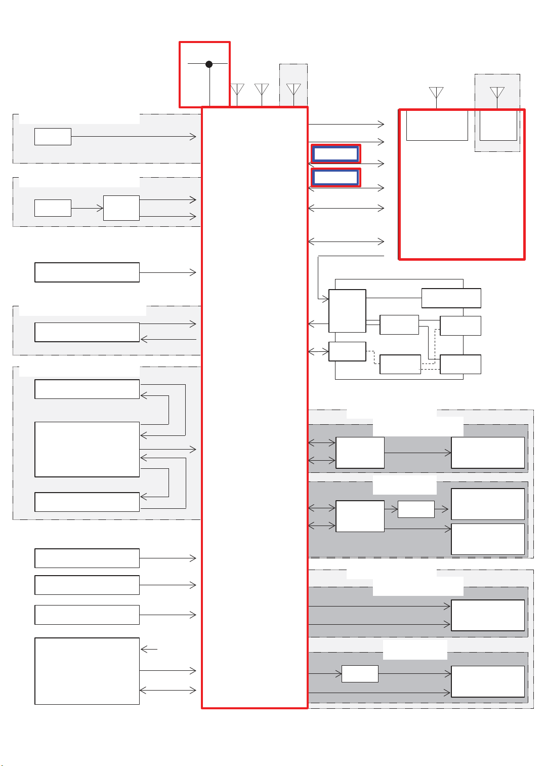
<System diagram>
37
HS-CAN
FM/AM
XM
NAVI only
GPS
11.6-inch
Wide Display only
WITHOUT DCM
MIC
WITH DCM
MIC
Steering switch
DCM
WITHOUT FRONT CAMERA
Rear View Camera
WITH FRONT CAMERA
Front View Camera
Analog
Analog(MIC)
MUTE
Command
Video
Power
Video
Power
Cockpit
Control
Unit
+B Back Up
IGN
CID Data
UART 2
BT Data
Wi-Fi Data
(11.6-inch Display)
ACC
External Input Terminal
W/H
4P
Bluetooth
ANT
Center Information Display
DCDC
HUB
Mini-Jack
USB
USB
Wi-Fi
ANT
Audio
Picture/
Movie/
Audio
Picture/
Movie/
Audio
Camera ECU
Rear View Camera
BATT (Back Up)
IGN/Acc
ILL/BRIGHT
CD/DVD DECK
Video
Power
Video
BATT
Deck V Bus
Deck D+,D-
Line out
CAN
Line out
CAN
Front
Rear
BRAND SPEAKER
AMP
(Brand)
AMP
(Brand)
STD SPEAKER
Front
Rear
DCM
WITHOUT DCM
WITH DCM
DCM
WITHOUT DCM
WITH DCM
Speaker
(Brand)
INP Speaker
(Brand)
Other Speaker
(Brand)
Speaker
(STD)
Speaker
(STD)
Page 38
(11) Air conditioner function
38
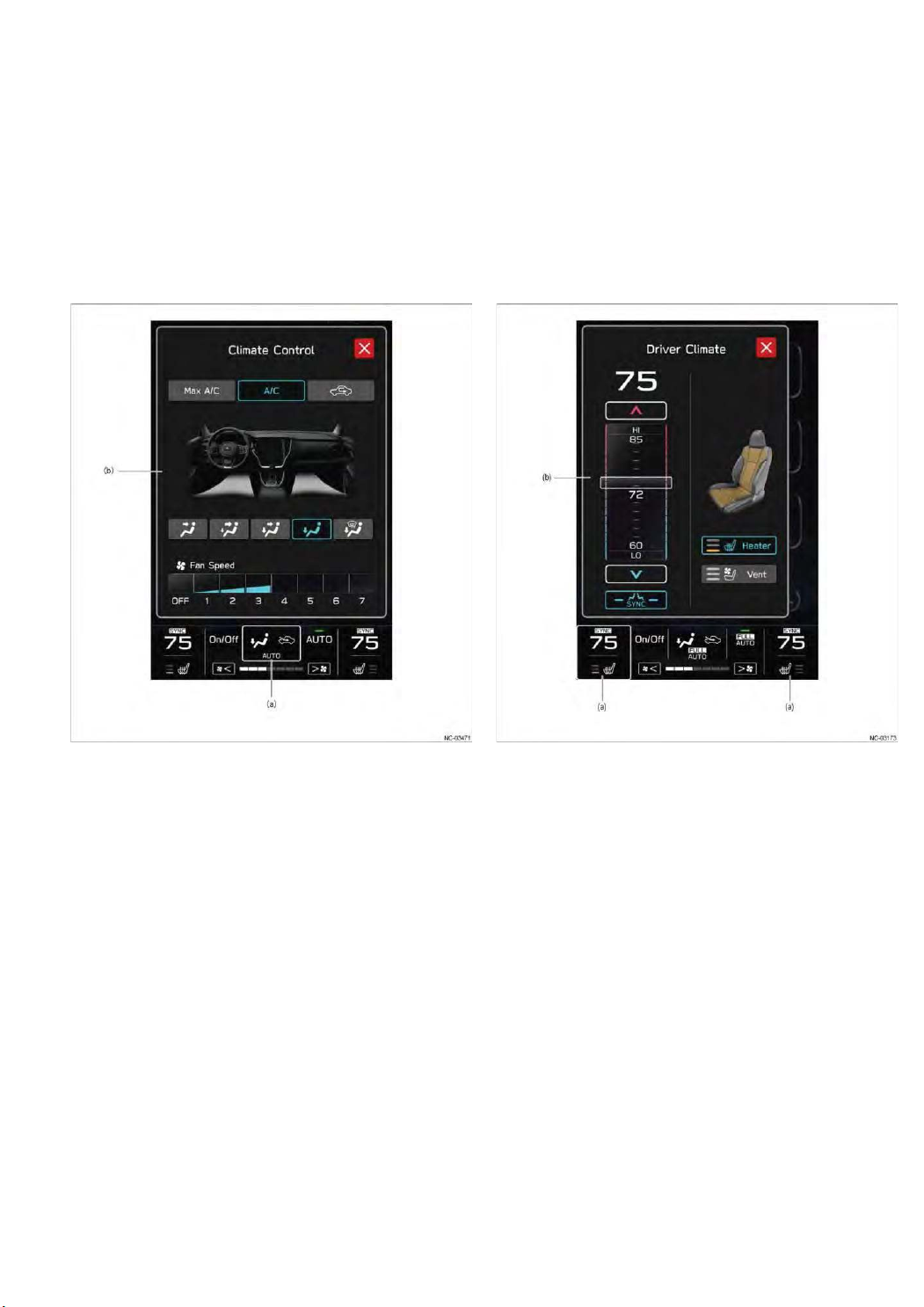
Depending on the vehicle specifications, there are 2 types of settings: single A/C type (7-inch twin
display) and dual A/C type (11.6-inch wide display).
Following on from functions implemented in conventional vehicles, such as "MAX A/C", "multi-step
air outlet mode", "voice recognition air conditioning" and "air conditioning ON/OFF", the system
improves comfort, convenience, and user-friendliness.
< Screen example >
(a) A/C control button
(b) Pop-up display
(a) Temperature detailed settings button
(b) Pop-up display
Page 39
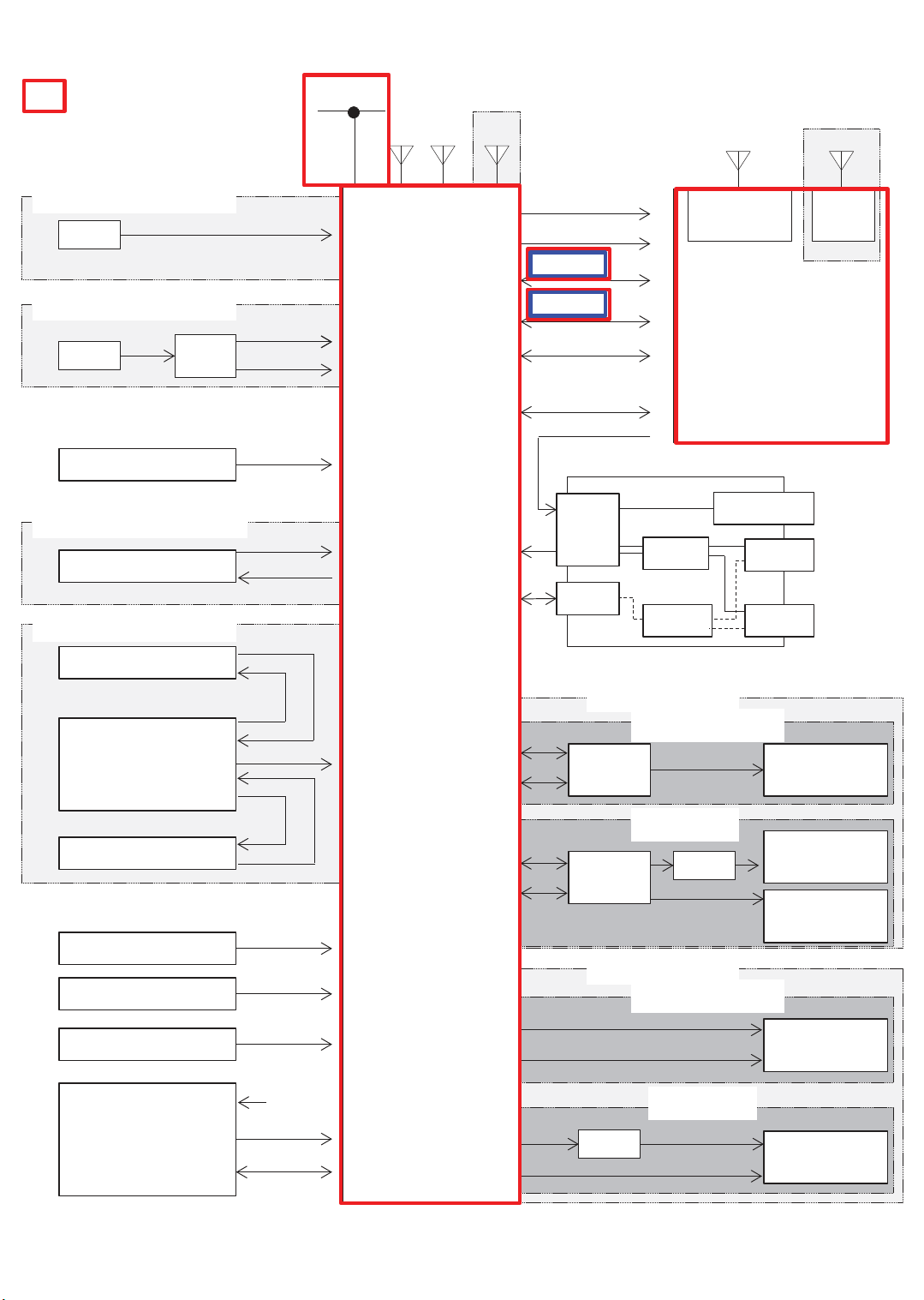
<System diagram>
39
A/C-related㻌 signal,and device
WITHOUT DCM
MIC
WITH DCM
MIC
Steering switch
DCM
WITHOUT FRONT CAMERA
Rear View Camera
WITH FRONT CAMERA
Front View Camera
Analog
Analog(MIC)
MUTE
Command
Video
Power
Video
Power
HS-CAN
FM/AM
XM
Cockpit
Control
Unit
NAVI only
GPS
+B Back Up
IGN
CID Data
UART 2
BT Data
Wi-Fi Data
(11.6-inch Display)
ACC
External Input Terminal
W/H
4P
DCDC
HUB
11.6-inch
Wide Display only
Bluetooth
ANT
Center Information Display
Mini-Jack
Wi-Fi
ANT
Audio
Picture/
USB
Movie/
Audio
USB
Picture/
Movie/
Audio
Camera ECU
Rear View Camera
BATT (Back Up)
IGN/Acc
ILL/BRIGHT
CD/DVD DECK
Video
Power
Video
BATT
Deck V Bus
Deck D+,D-
Line out
CAN
Line out
CAN
Front
Rear
BRAND SPEAKER
AMP
(Brand)
AMP
(Brand)
STD SPEAKER
Front
Rear
DCM
WITHOUT DCM
WITH DCM
DCM
WITHOUT DCM
WITH DCM
Speaker
(Brand)
INP Speaker
(Brand)
Other Speaker
(Brand)
Speaker
(STD)
Speaker
(STD)
Page 40
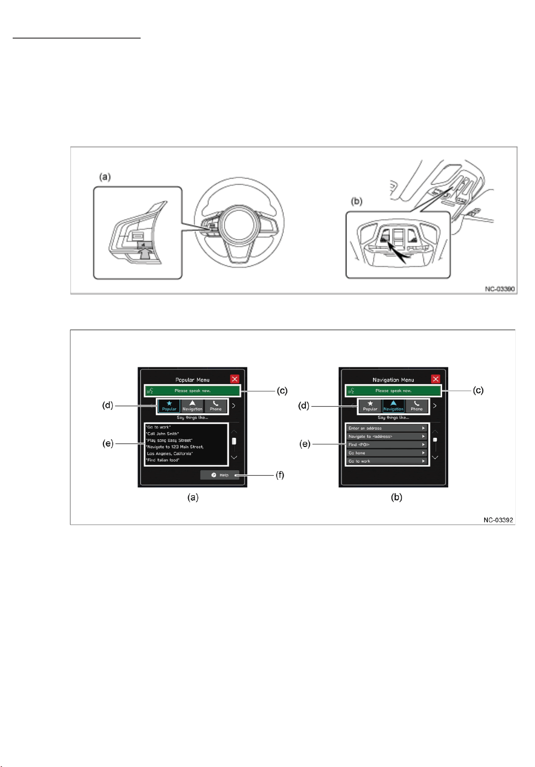
4.5 Function ( Others )
40
(1) Voice Recognition Function
Pressing the talk switch located on the steering wheel activates the voice recognition function.
The user can speak into the microphone located in the map light to run commands, referring to
the samples displayed on the infotainment system screen.
If the system fails to recognize the voice commands, the user can alternatively touch items
displayed on the screen to run the commands.
< Screen sample >
(a) Talk switch (b) Microphone
(2) Speaker
The following three types of speaker systems have been set according to the grade: 4-speaker, 6speaker (standard system) and Harman/Kardon® audio systems.
䞉 Standard audio system ( By grade )
䞉Harman/Kardon® audio system ( By grade )
The audio system has been developed by adopting the clear acoustics and latest
technologies provided by Harman to enable listeners to enjoy the compressed sound
sources of various formats at high sound quality, delivering more faithful reproduction
of the sound source data and excellent sound diffusion.
Page 41
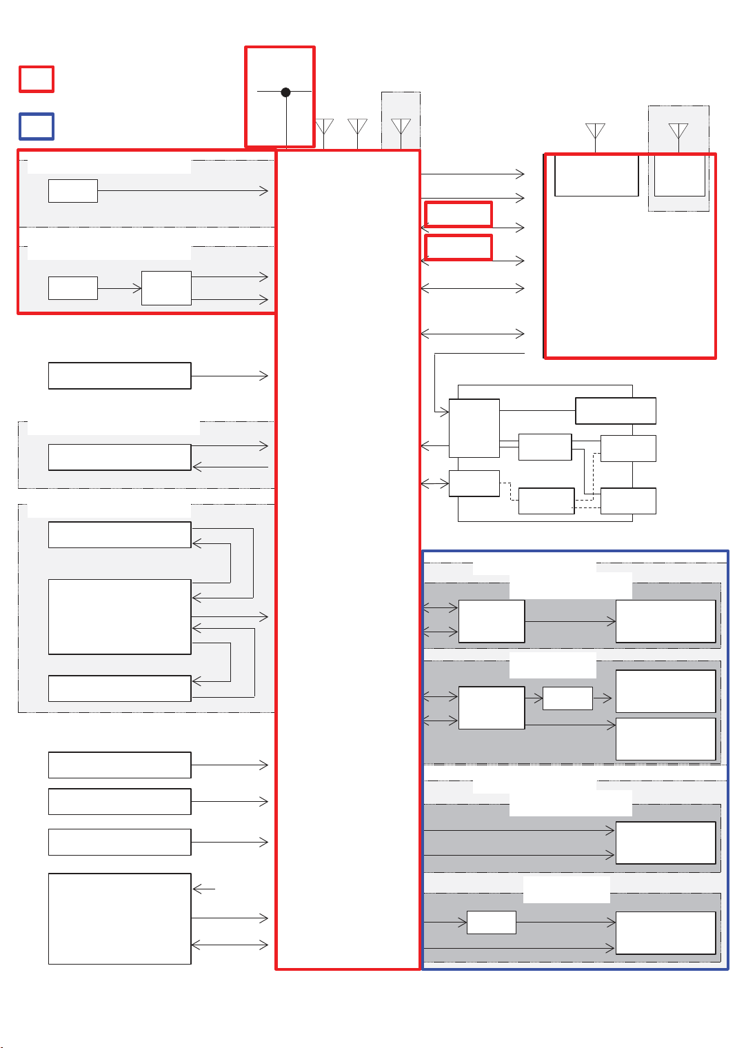
<System diagram>
41
Voice Recognition-related㻌
signal,and device
Speaker-related㻌 signal,and
device
WITHOUT DCM
MIC
WITH DCM
MIC
Steering switch
DCM
WITHOUT FRONT CAMERA
Rear View Camera
WITH FRONT CAMERA
Front View Camera
Analog
Analog(MIC)
MUTE
Command
Video
Power
Video
Power
HS-CAN
FM/AM
XM
Cockpit
Control
Unit
NAVI only
GPS
+B Back Up
IGN
CID Data
UART 2
BT Data
Wi-Fi Data
(11.6-inch Display)
ACC
External Input Terminal
W/H
4P
DCDC
HUB
11.6-inch
Wide Display only
Bluetooth
ANT
Center Information Display
Mini-Jack
Wi-Fi
ANT
Audio
Picture/
USB
Movie/
Audio
USB
Picture/
Movie/
Audio
Camera ECU
Rear View Camera
BATT (Back Up)
IGN/Acc
ILL/BRIGHT
CD/DVD DECK
Video
Power
Video
BATT
Deck V Bus
Deck D+,D-
Line out
CAN
Line out
CAN
Front
Rear
Front
Rear
BRAND SPEAKER
WITHOUT DCM
AMP
(Brand)
WITH DCM
AMP
(Brand)
STD SPEAKER
WITHOUT DCM
WITH DCM
DCM
DCM
Speaker
(Brand)
INP Speaker
(Brand)
Other Speaker
(Brand)
Speaker
(STD)
Speaker
(STD)
Page 42
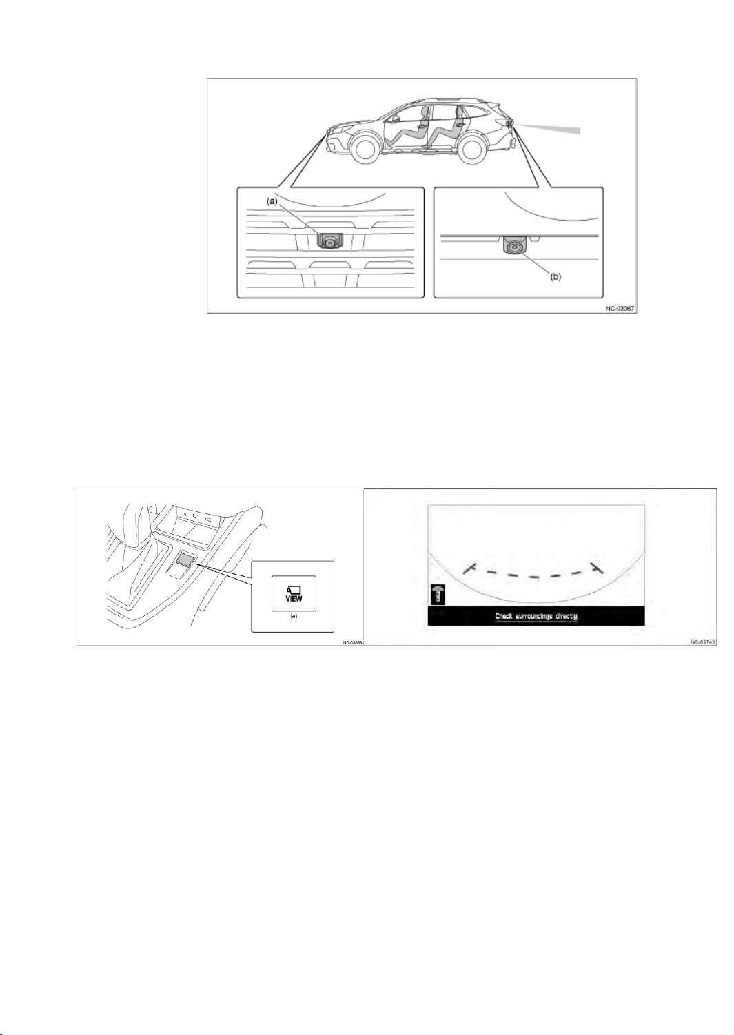
(3) Camera ( Front View Camera / Rear View Camera ( by grade ) )
42
Location
䙟 Front View Camera ( by grade)
A front view monitor (by grade) has been set for displaying images captured by the camera
mounted on the front of the vehicle body onto the Center Information Display (CID).
The front view monitor screen is displayed by pressing the VIEW switch in the center console.
Also, operations such as turning the link with the shift position on or off and adjusting the
contrast or brightness can be performed from the customization screen of the Center
Information Display (CID).
䙟 Rear View Camera
A rear view monitor has been set for displaying images captured by the camera mounted on
the rear of the vehicle body onto the Center Information Display (CID).
The rear view camera capturing the rear of the vehicle supports the driver when checking the
rear of the vehicle by displaying images from the blind spot of the driver.
# Delay function for rear camera image cancellation
A function has been added to delay the cancellation of the rear camera image display by 9
seconds when the shift position is changed from "R" to "D".
This maintains the image when turning the steering wheel repeatedly. The rear camera image
display is canceled when the shift position is changed to "P" or the vehicle speed rises to 5
mph (8 km/h) or higher.
Page 43
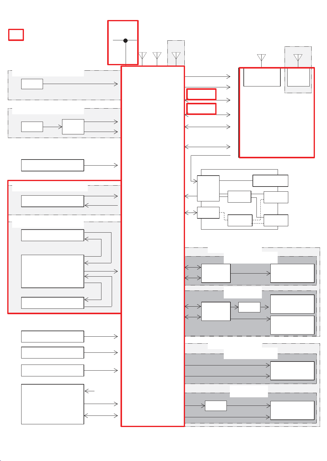
<System diagram>
43
Camera-related㻌 signal,and
device
WITHOUT DCM
MIC
WITH DCM
MIC
Steering switch
DCM
WITHOUT FRONT CAMERA
Rear View Camera
WITH FRONT CAMERA
Front View Camera
Analog
Analog(MIC)
MUTE
Command
Video
Power
Video
Power
HS-CAN
FM/AM
XM
Cockpit
Control
Unit
NAVI only
GPS
+B Back Up
IGN
CID Data
UART 2
BT Data
Wi-Fi Data
(11.6-inch Display)
ACC
External Input Terminal
W/H
4P
DCDC
HUB
11.6-inch
Wide Display only
Bluetooth
ANT
Center Information Display
Mini-Jack
Wi-Fi
ANT
Audio
Picture/
USB
Movie/
Audio
USB
Picture/
Movie/
Audio
Camera ECU
Rear View Camera
BATT (Back Up)
IGN/Acc
ILL/BRIGHT
CD/DVD DECK
Video
Power
Video
BATT
Deck V Bus
Deck D+,D-
Line out
CAN
Line out
CAN
Front
Rear
Front
Rear
BRAND SPEAKER
WITHOUT DCM
AMP
(Brand)
WITH DCM
AMP
(Brand)
STD SPEAKER
WITHOUT DCM
WITH DCM
DCM
DCM
Speaker
(Brand)
INP Speaker
(Brand)
Other Speaker
(Brand)
Speaker
(STD)
Speaker
(STD)
Page 44
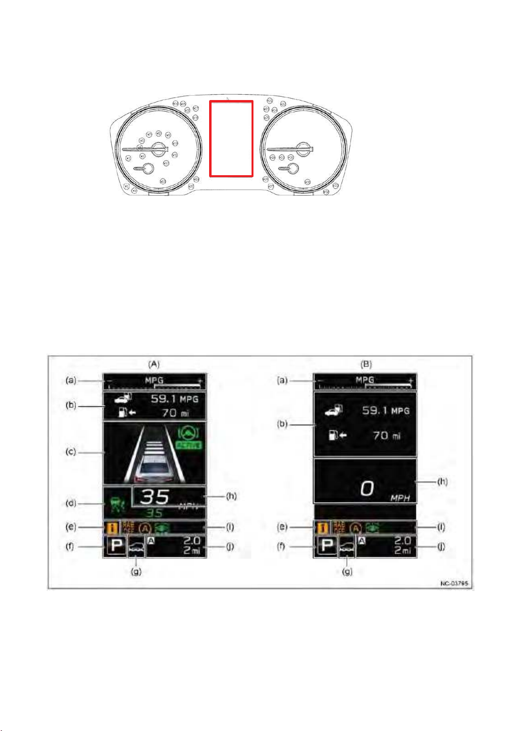
(4) Telltale
44
By specification, various kinds of information (including alerts, etc.) are displayed on the multiinformation display.
The presence/absence of tell-tales, and the design, depend on vehicle grade, equipment, etc.
䙟 Multi-Information Display (MID)
㻌 In addition to driving conditions and alerts displayed when EyeSight is in use, the multi-
information display is used to display various kinds of driving-related information on the 4.2-inch
screen.
CCU create the image of the MID by CAN information, and sends to the MID.
㻌 The content displayed on the screen differ depending on whether or not EyeSight is running.
(A) EyeSight (Active) (B) EyeSight (Nonactive)
(a) The ECO gauge/information display (f) Shift position display
(b) The basic screen (g) SI-DRIVE display / X-MODE display
(c) EyeSight screen (h) Vehicle speed
(d) EyeSight screnn/ Cruise control screen ( I ) Fixed Warning Display
(e) Information marks ( j ) Trip meter/odometer
Page 45
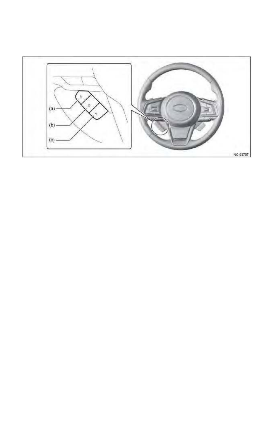
䙟 Multi-Information Display (MID) Operation switch
45
By specification, switches for changing the multi-information display are located on the
steering wheel, enabling safe operation even while driving.
( a ) 䕧 Back switch ( b ) i switch ( c ) 䕱 Feed switch
Page 46
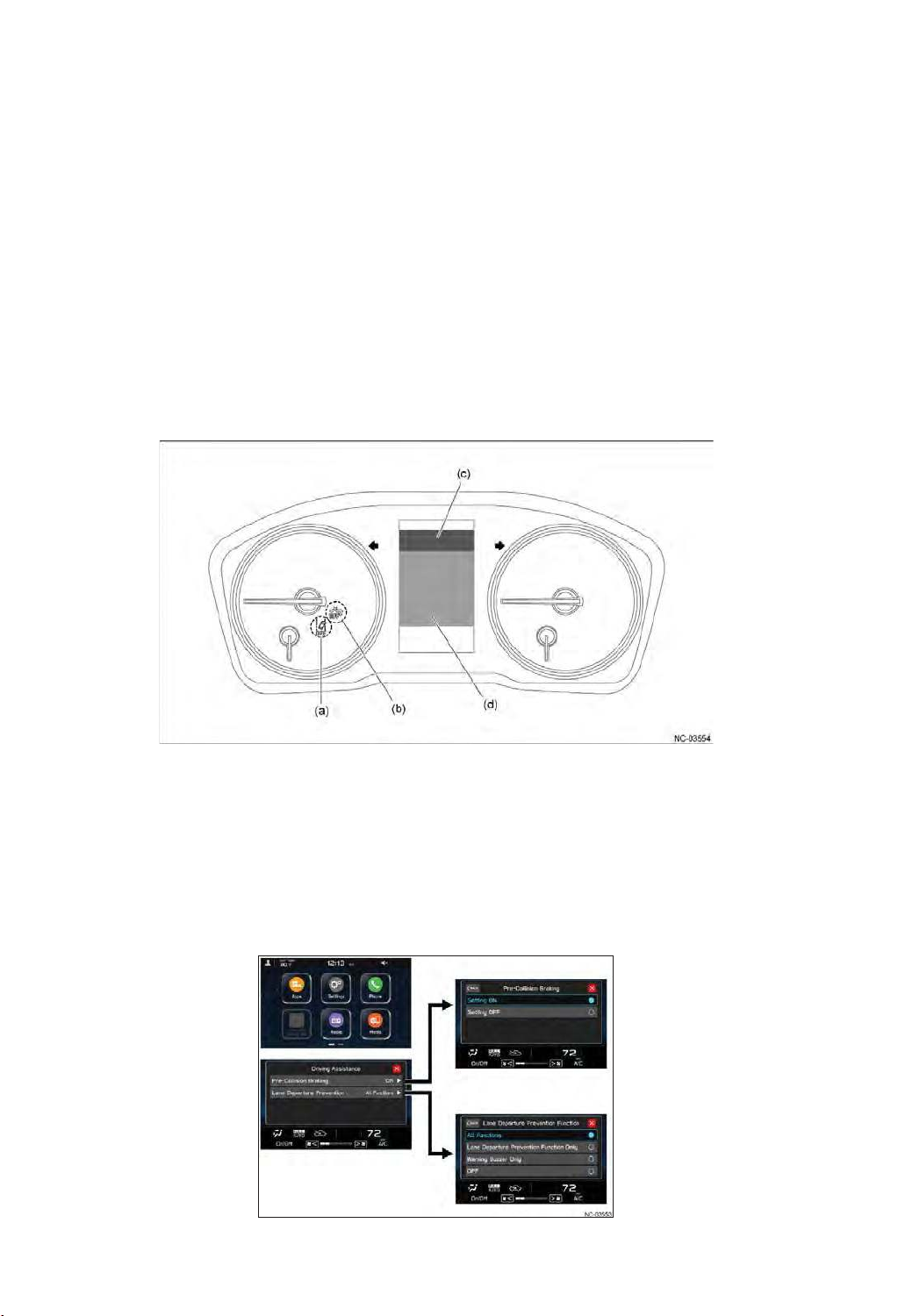
䙟 The OFF display lights for the pre-collision braking system, lane departure warning
46
The OFF display lights for the pre-collision braking system and lane departure warning are located
in the combination meter.
The basic screen area shows fuel consumption, vehicle speed, and similar. In addition, when
EyeSight warnings or system errors occur, interrupting screens are displayed.
The EyeSight display area shows the operating status of the following functions.
- Pre-collision braking system
- Pre-collision braking assist system
- Adaptive cruise control and conventional cruise control
- Lane departure suppression function
- The center of the lane keeping control, Following the preceding vehicle steering control
- AT improper start suppression control
- Distance warning
- Lane departure warning
- Lane sway warning
- The preceding vehicle starting Announcement
(a) The OFF display lights for the lane departure warning (c) Basic screen area
(b) The OFF display lights for the pre-collision braking system (d) EyeSight display area
Individual items in the Center Instrument Display (CID) can be turned on or off by selecting them.
When a function is off, a display light illuminates in the combination meter.
< 7-inch dual display Audio >
Page 47
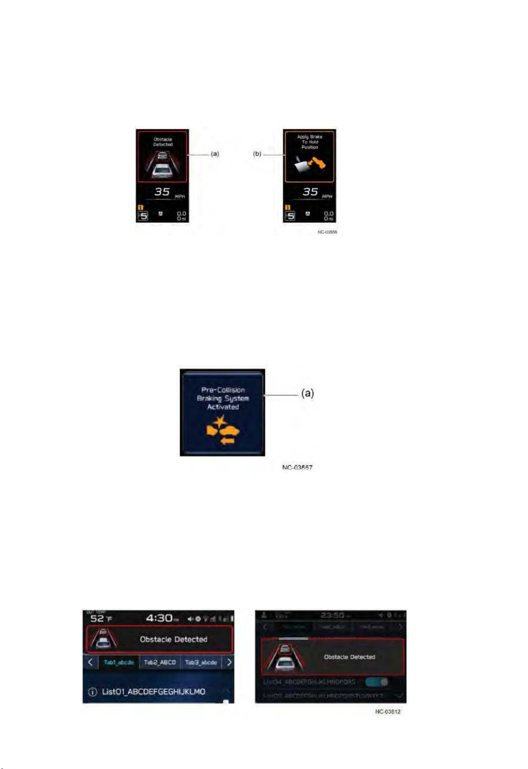
䙟 The pre-collision braking system
47
This function helps the driver to avoid collisions by issuing a warning when there is a possibility of
a collision, generally with a vehicle in front.
If the driver, however, does not take action to avoid the collision, the brakes are automatically
applied directly before the collision to mitigate collision damage or avoid it. At the same time, a
warning is displayed in the meter panel.
(a) Red frame and preceding vehicle flashing (b) Yellow frame illuminated
ͻ Operation notification
In conventional vehicles, the alarm screen is displayed only while pre-collision braking system is
activated. If pre-collision braking system is activated only briefly, it is possible that the driver
will be unaware that the pre-collision braking system had been activated.
Therefore, the interrupting screen in the Multi-Information Display (MID) continues to be
displayed for a certain duration. Extending the display time makes it more likely that the driver
will realize that pre-collision braking system had been activated.
(a) Display for a fixed time
ͻ Warning indication to a center information display
When pre-collision braking system is activated and a depress brake warning occurs, a
warning screen is also displayed on the Center Information Display (CID), in order to provide
information to the other passengers, too.
With this, the aim is to improve safety by providing earlier notification that the driver is
inattentive and by giving passengers an opportunity to alert the driver.
< 7-inch dual display Audio >
< 11.6-inch dual display Audio, Navigation >
Page 48
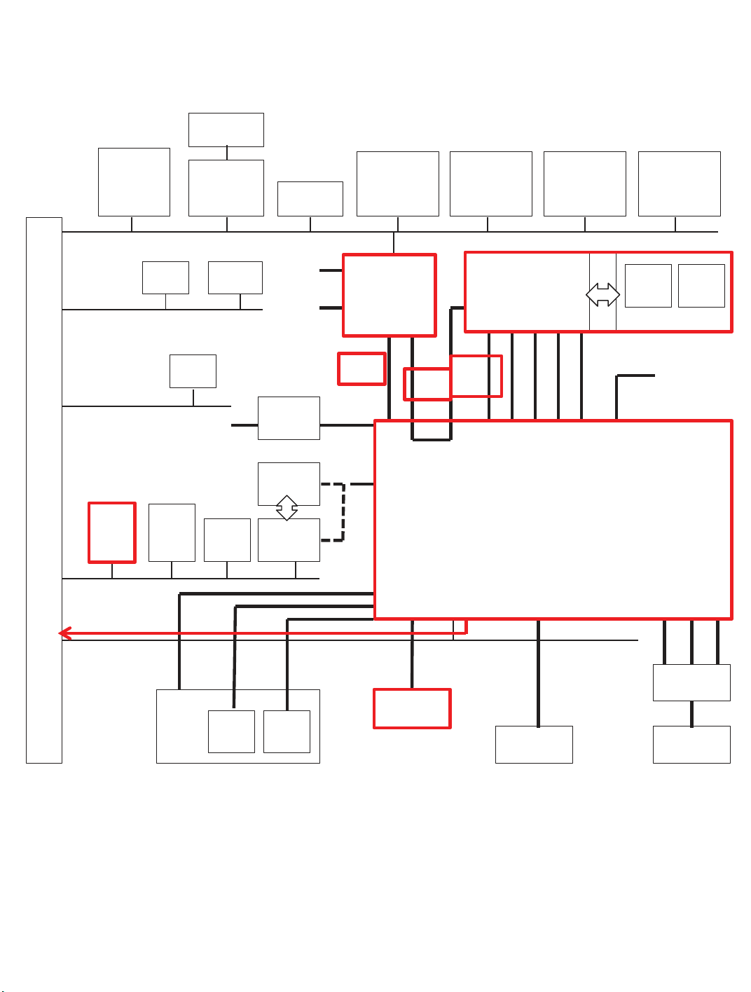
< System diagram : CAN communication>
48
Hazard
Central
Gateway
CU
Driver
Monitoring
Unit
Body
CAN
Chassis
CAN
Power Unit
CAN
Stereo
Camera
TPMS
CU
ECU
+B_backup
Radar
Sensor
LH
Body
Integration
Unit
VDC CU
RAB
CU
A/C CU
+B_
direct
IGN
CD
Rear
Camera
Camera
CU
Twin +
4.2inch TFT
Meter
LDVS
USB2.0
NTSC/
6.0V
Power
Rear gate
CU
UART
UART
Power
Seat
CU
CID
(11.6inch)
LVDS
/RF
Wi-Fi
BT
Cockpit Control Unit
Outer
Mirror
CU LH
IGN
+B_backup
Headlamp
Automatic
Leveling LH
CID
(7inch)
+B_direct/
+B_backup
IGN/REV
With
CID
(7inch)
Advanced
Safety CAN
Outside
Connection
CAN
+B
AUX
Analog
Jack
Pin
USB2.0
USB
㽢2
Resistance
Division
Sterring
SW
Antenna
XM
RF RF +B
Antenna
AMP
Antenna
AM / FM
Page 49
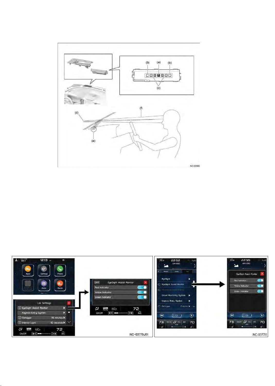
(5) EyeSight assist monitor
49
LED lights shine onto the windshield, with colors and flashing patterns changing according to
the danger level, to provide an easy-to-understand warning to the driver.
(a) Green (d) Virtual image display location
(b) Yellow (e) Mounting position
(c) Red (f) Optical path
Individual items in the Center Instrument Display (CID) can be turned on or off by selecting them.
It turns off when the ignition switch is OFF.
< 11.6-inch display audio ,
< 7-inch dual display Audio >
11.6-inch display navigation >
Page 50
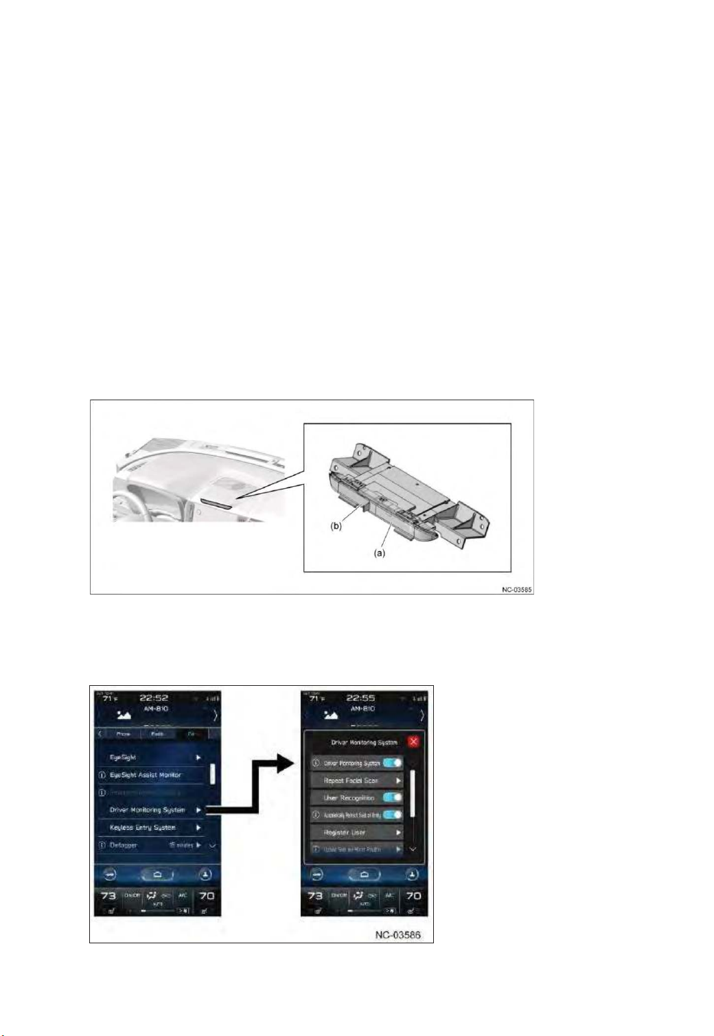
(6) Driver monitoring system
50
With more older and younger drivers on the road, collisions caused by driver inattentiveness
(looking to the side or falling asleep) are increasing. Therefore, more modern vehicles are being
equipped with advanced safety technology such as EyeSight.
While advanced safety technology is useful for reducing the task load imposed on the driver, it can
also be a cause of inattention, due to drivers carelessly thinking that the "advanced safety
technology will keep the car from being involved in any collisions".
To combat this, we have developed the driver monitoring system, that serves as the vehicle's "eyes"
within the passenger compartment. The vehicle monitors the driver's status and provides alerts at
the appropriate times.
䙟Principles of the driver monitoring system
An infrared LED is projected on the driver and the camera captures images. The captured
images are used to calculate the driver's face orientation, closing and opening of the eyes, and
facial characteristics.
䙟 Location
The components of the driver monitoring system are located in the upper center
portion of the instrument panel.
(a) Infrared LED (b) Camera
Individual items in the Center Information Display (CID) can be turned on or off by selecting them.
Page 51
< Individual recognition>
51
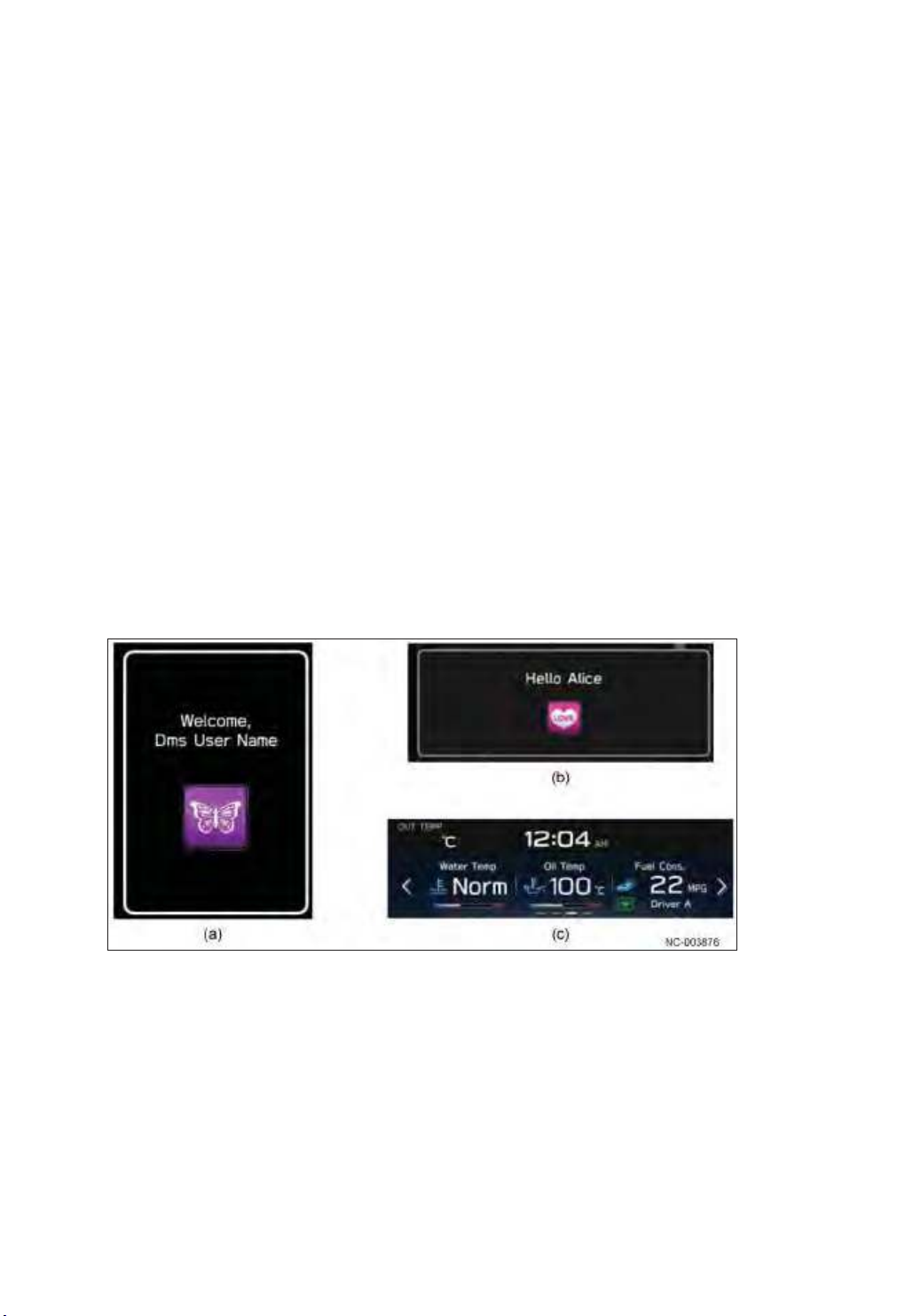
This system is linked to the opening and closing of the door and recognizes individuals. When the
driver sits in the seat and recognition is completed, the results are displayed graphically on the
Multi-Information Display (MID).
㻌 After this time, the various settings particular to that driver are automatically adjusted. These
include seat position, door mirror angle, contents displayed on the meter screen, and A/C
settings.
< Inattentive alarm >
If the driver's face is continuously turned well outside a predetermined range, the system infers the driver
is not watching the road.
If the system infers the driver is not watching the road, the driver is warned with a buzzer sound and
meter display (MID).
< Dozing / drowsiness warning >
㻌 If the driver's eyes remained continuously closed, the system infers that the driver is falling asleep.
㻌 If the system infers mild drowsiness, the driver is warned with a meter display (MID).
If the system infers the driver is falling asleep or is extremely drowsy, the driver is warned with a
buzzer and meter display (MID).
Furthermore, in the case of falling asleep and extreme drowsiness only, the audio is muted so that
the buzzer is more easily heard.
< Screen example >
(a) Recognition result display ( MID ) (b) Re-recognition result display ( CID )
(c) Individual fuel consumption display( CID )
Page 52
(7) Smartphone-linked connectivity
52
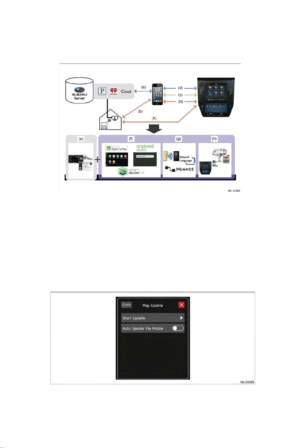
The system can link up with smartphones that have Apple CarPlay, Android Auto, or Smart
Device Link (SDL)-compatible apps installed.
The system is compatible with wireless software and map data updates using Wi-Fi (OTA)
and simple pairing functions with Near Field Communication (NFC).
D** H,QWHUQHWUDGLR
E:L)L I(QKDQFHG6PDUWSKRQH/LQNLQJ
F86% J(QKDQFHG9RLFHUHFRJQLWLRQ
G%OXHWRRWK KUpdate Over The Air
䙟Map update Over The Air䠄MOTA䠅䠅
Map data stored on the navigation system can be updated using Wi-Fi communications.
< Reference >
Wi-Fi function is disabled by default. Therefore, Wi-Fi function has to be turned on
before the map update function can be used.
Page 53
(8) Telematics
53
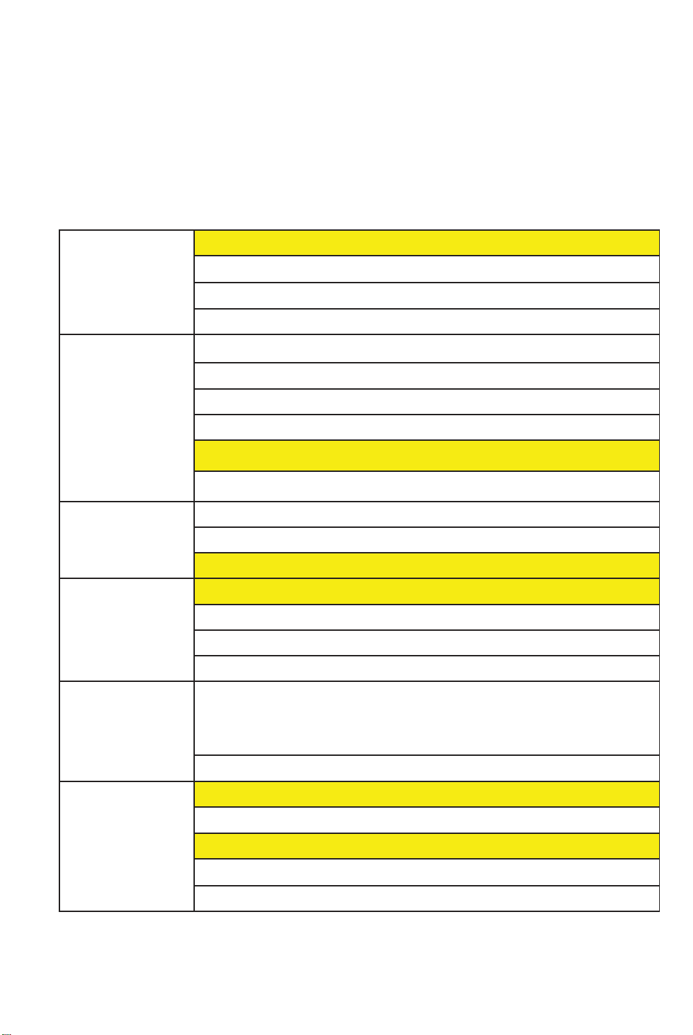
Telematics is a combination of the words "Telecommunications" and "Informatics", and refers
to the services of information and contents provided via two-way communication technology
between a mobile body such as a vehicle with built-in communication system and the outside
world, and also to the associated businesses.
SUBARU has already introduced various telematics services such as remote door lock/unlock
and SOS/roadside assistance, but we installed next-generation telematics systems to provide
even more comprehensive services.
Voice Call SUBARU Concierge
Advanced Automatic Collision Notification
SOS Emergency Assistance
Enhanced Roadside Assistance
Remote Services Remote Engine Start(Includes Climate Control/Heated Seats)
Remote Lock & Unlock
Remote Horn & Lights
Remote Vehicle Locator
Destination to Vehicle(to Navi or Text depends on the vehicle type)
Vehicle Condition Check
Vehicle Alerts Boundary Alert
Speed Alert
Curfew Alert
Customer Touch
Point
Security - Stolen Vehicle Recovery Plus
Connected Vehicle
Feature
Service Appointment Scheduler
Maintenance Notifications
Diagnostic Alerts
Vehicle Health Report
(SVR Plus includes Vehicle㻌 Immobilization/Mobilization)
- Stolen Vehicle Immobilizer
- Theft vehicle flashing light
Vehicle Security Alarm Notification
SUBARU STARLINK system Update
Map update Over The Air(MOTA)
Wi-Fi Hotspot
Call volume change function (Telematics call)
Drive recorder
Page 54
< System cofiguration >
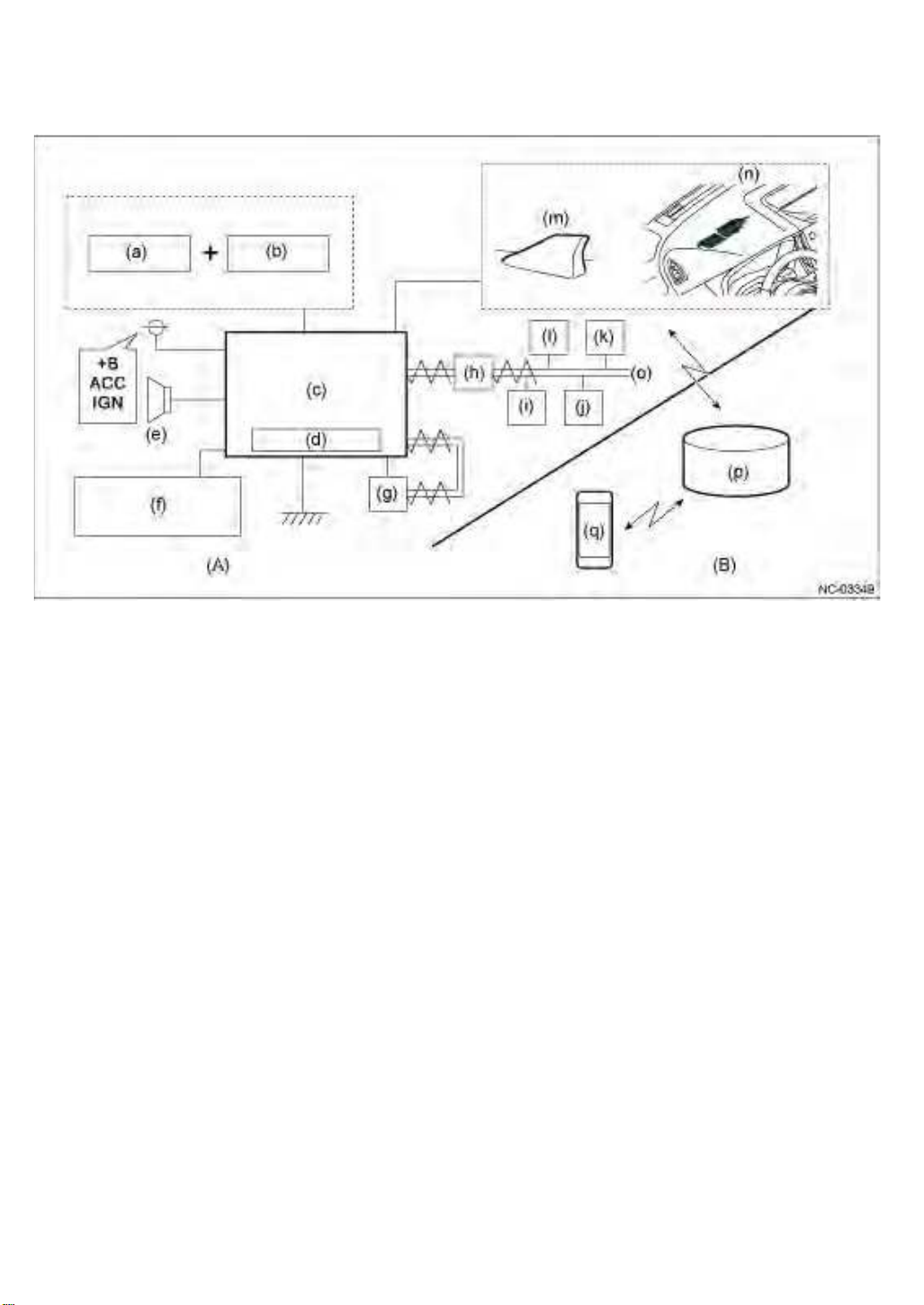
54
(A) SUBARU PART (B) SOA PART
(a) Microphone (j) Meter
(b) Switches with integrated indicators (k) E/G ECU
(c) Data Communication Module䠄DCM䠅 (l) TCU
(d) Back Up Battery (m) Roof antenna䠄TEL䠅
(e) Speaker (n) Instrument Panel Sub-antenna (TEL/GPS)
(f) Navi/Display Audio (o) CAN Communication
(g) A/B ECU (p) External Server
(h) CGW (q) Smartphone
(i) BIU
Page 55
< System Block Diagram >
55
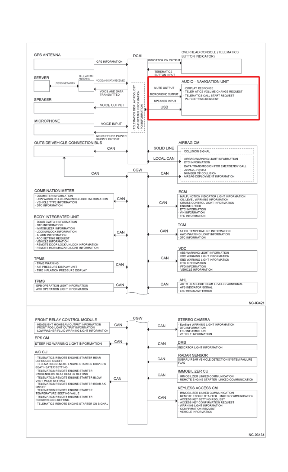
DCM-related㻌 signal,and device
Page 56
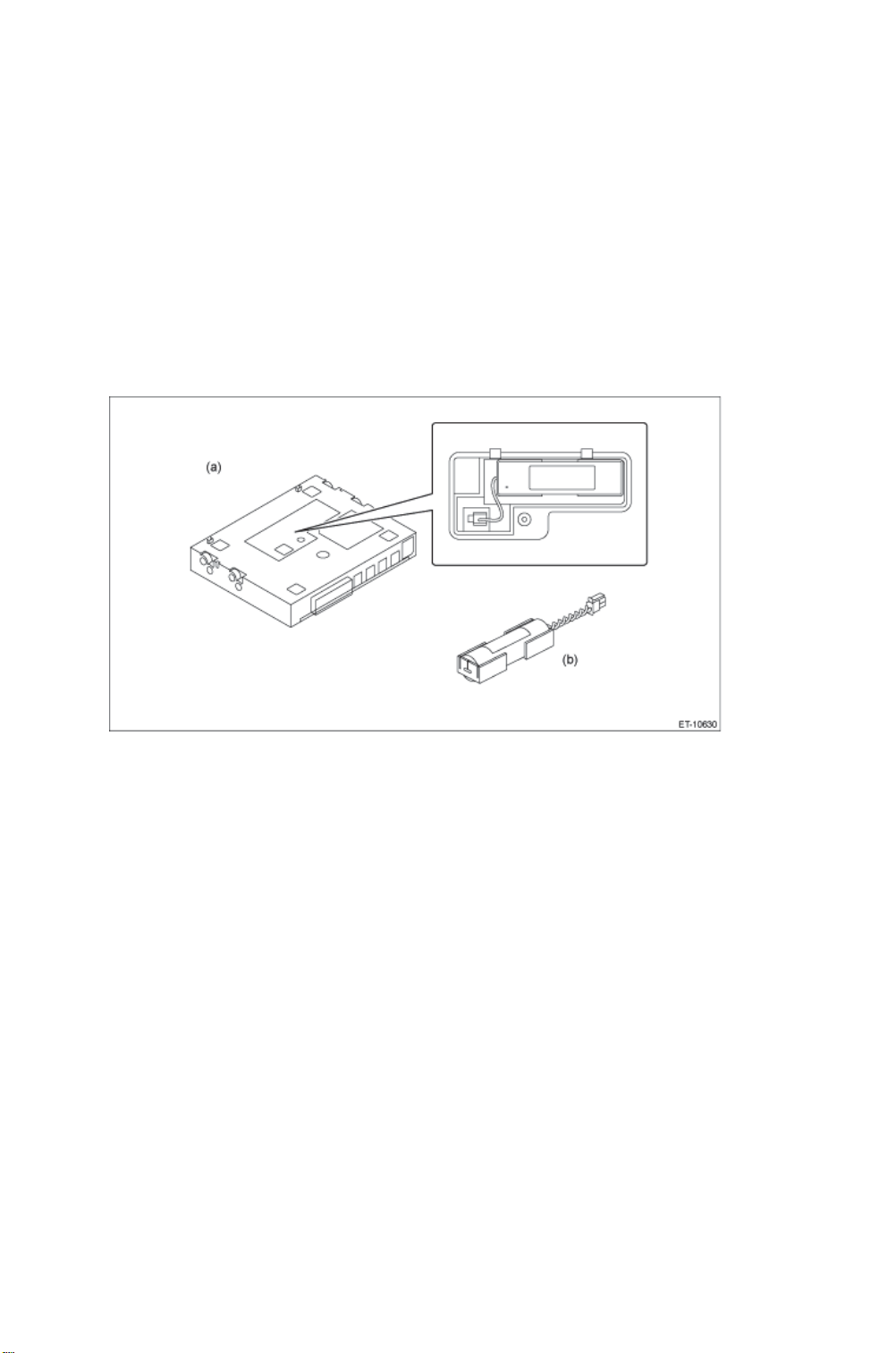
䙟 Data Communication Module䠄DCM䠅
56
In-vehicle data communication uses CAN to transmit/receive data to/from each unit, while
the external communication takes place with the server via the roof antenna and the subantenna in the instrument panel to provide telematics services.
The data communication module that is the heart of the system is located in the center of the
automobile and in the passenger compartment in order to reduce the impact of collisions.
By specification, in the event of a collision (forward collision) or a power supply failure from
the vehicle battery during an SOS call, the DCM internal battery (BUB: Back Up Battery)
provides power so that emergency reports can continue.
The module adopted a secondary battery, which recharges from the vehicle battery when the
ignition switch is ON.
(a) DCM (b) Back Up Battery䠄BUB䠅
Page 57
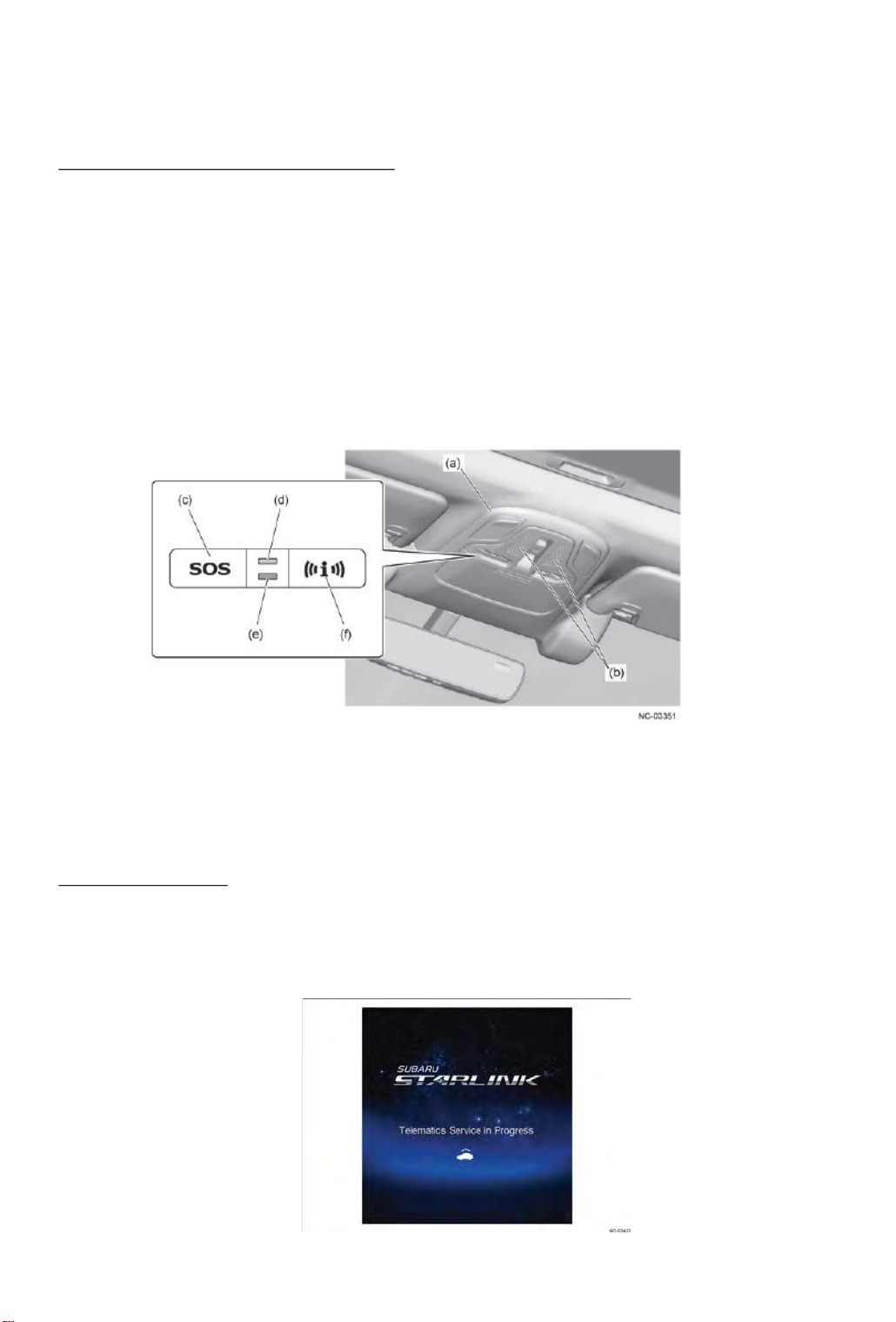
䙟 User interface
57
The UI of the system enables communication with the outside by the switches with integrated
indicators, service displays that use the navigation system or audio H/U display, and a voice
guidance function.
Switches with integrated indicators
Communication with the outside can be made immediately by operating the switches, and
the switches are located in the overhead console/EyeSight camera cover section to ensure
ease of use in an emergency situation.
By specification, a quick press of the switch starts communication with each corresponding
service, while pressing and holding the switch cancels communication.
< SOS switch ( SOS Emergency Assistance ) >
In an emergency, the user contacts a Telematics Customer Care Advisor.
< iCall switch ( Enhanced Roadside Assistance䠅 >
In the event of a vehicle failure or other issue, the user can contact road services.
Also, the user can select road service or the concierge via the head unit.
(a) Overhead console (d) GREEN LED indicator
(b) Microphone Opening (e) RED LED indicator
(c) SOS 䝇䜲䝑䝏䠄SOS Emergency Assistance䠅 (f) iCall 䝇䜲䝑䝏䠄Enhanced Roadside Assistance䠅
*1䠖Diagnostic Trouble Code
*2䠖Advanced Automatic Collision Notification
Display indication
By specification, when the navigation system or audio H/U receives a mute signal from the
DCM, the navigation system or audio system stops audio playback, and displays the following
across the full screen of the touch panel display. This ensures that the user is made visually
aware that the service has been activated.
Page 58
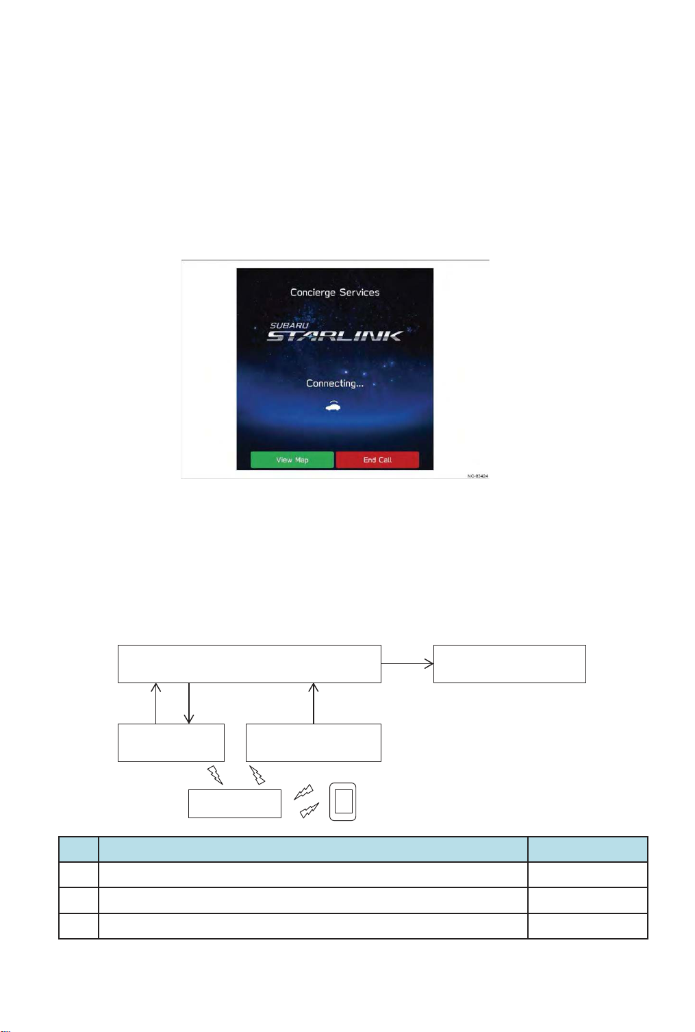
1) SUBARU Concierge
58
This function enables the user to telephone the call center and select the location where they
want to go (the destination) through the communication with the operator, and then have the
destination set in the navigation system.
Once the destination is decided, the operator sends the destination information to the vehicle,
and the destination is automatically set up in the onboard navigation system. This allows the
user to safely set a destination while driving.
With the concierge service, the user briefly presses the iCall switch and then selects the
concierge service option on the navigation system or audio H/U screen.
In addition, the service can be started from the audio H/U screen, without any need to press
the iCall switch.
2) Destination to Vehicle(to Navi or Text depends on the vehicle type)
With this function, destination information can be sent from a dedicated mobile app on a
smartphone to the vehicle, where it is set as the destination on the onboard navigation system.
The user can set the destination via the app before getting into the vehicle, then immediately
head for the destination as soon as they get into the vehicle.
DCM Navigation CM
1 3 1
Main antenna
(roof)
Server
No.
1 Destination setting information is output from the server to DCM (antenna) Server
2 Destination setting information is output from the server to DCM (antenna) DCM
3 The result is sent to the server DCM
Sub antenna
(Instrument Panel)
ไᚚෆᐜ ᑐᛂ䝴䝙䝑䝖
2
Smartphone
Page 59
3) Curfew Alert
59
This function allows the user to set a specific time and have the system notify them if the
vehicle is being used at that time.
The system informs the driver through the onboard audio/navigation system that the set time
is approaching.
4) Service Appointment Schedule
With this function, the onboard audio/navigation system accesses the server of SUBARU of
America to display the dealer reservation screen only for the users, on which the users can
make a reservation to bring the vehicle into the dealer from the vehicle itself.
In addition, dealer reservations can be suggested depending on vehicle status or on current
service campaigns, and the user can make a phone call to a specified dealer.
* This can only be used when the onboard audio/navigation systems are available for handsfree calls.
5) SUBARU STARLINK system Update
This is a function that the vehicle downloads data for DCM update from the server using
wireless communication and update the DCM.
When an update was necessary due to a service campaign or other reason, the customer
was required to make a reservation with the dealer and take the vehicle in themselves, but
this function reduces the frequency of such occurrences.
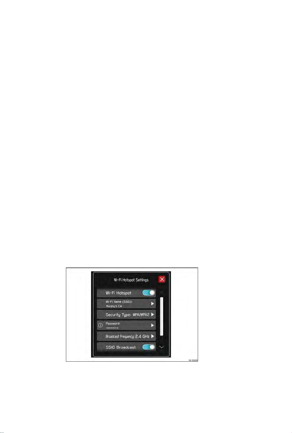
6) Wi-Fi Hotspot
This function provides an Internet connection service with the vehicle becoming an access
point for wireless LAN using LTE high-speed communication.
The user can use the Internet service by connecting their PC, game machine, tablet, or
other device to the vehicle.
Page 60

60
Page 61
5. Diagnosis knowledge
61
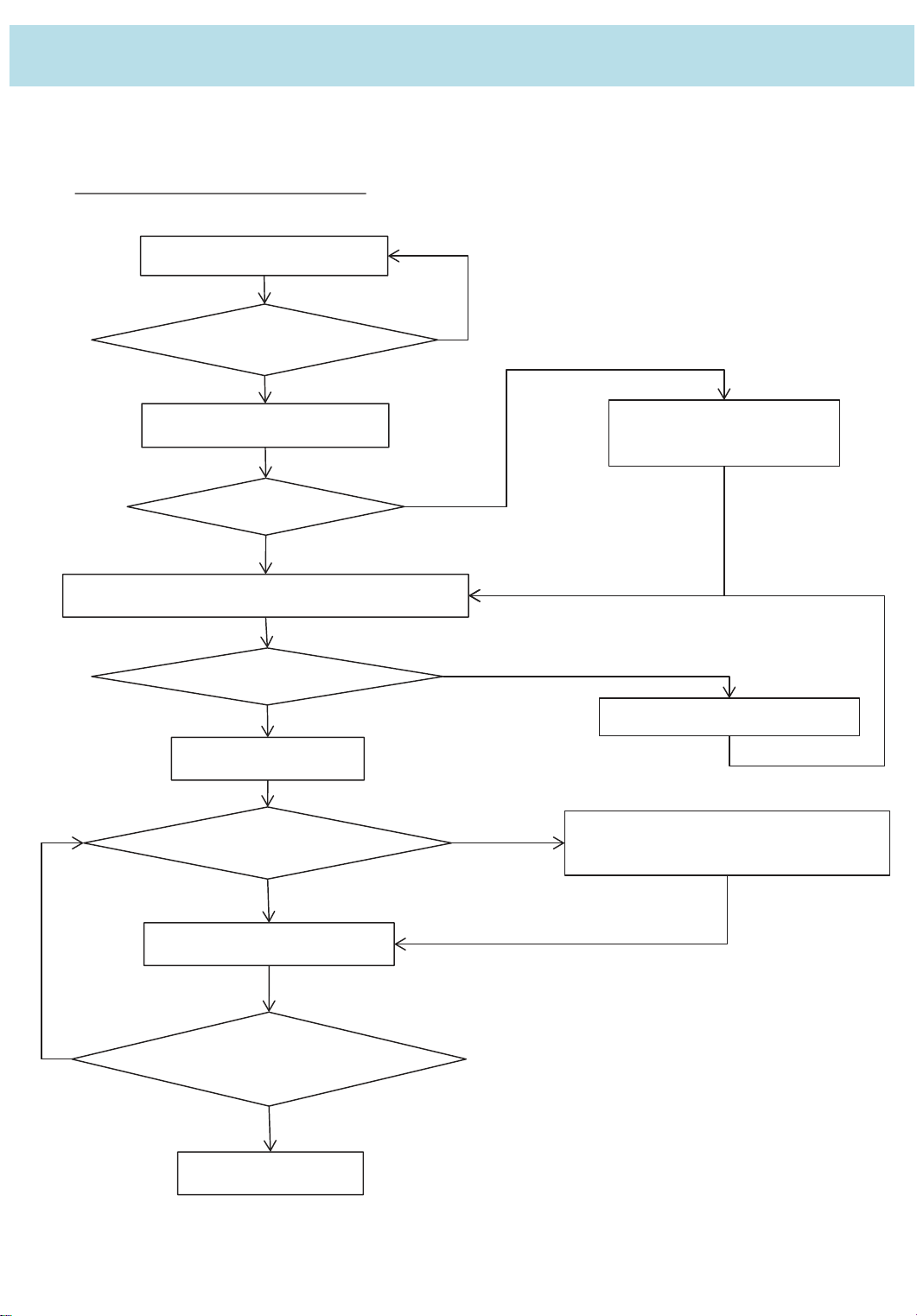
When malfunction occurs, please push forward a diagnosis according to a procedure listed in a
repair book.
5.1 Basic Daignostic Procedure
1.Perform customer interview
Did you interview the
customer?
Yes
2. Perform basic inspection
Is the check
result OK?
Yes
3.Check SUBARU Select Monitor communication
Is communication
possible?
Yes
4.Check DTC
Are any DTCs
displayed? (Current
malfunction)
No
Repair the faulty part found in
basic inspection
No
No
Check the communication circuit.
No
Record the DTC, time stamp and
freeze frame data.
Yes
5 .Perform diagnosis.
Yes
Are any DTCs displayed?
(Current malfunction)
No
Finish the diagnosis
Page 62

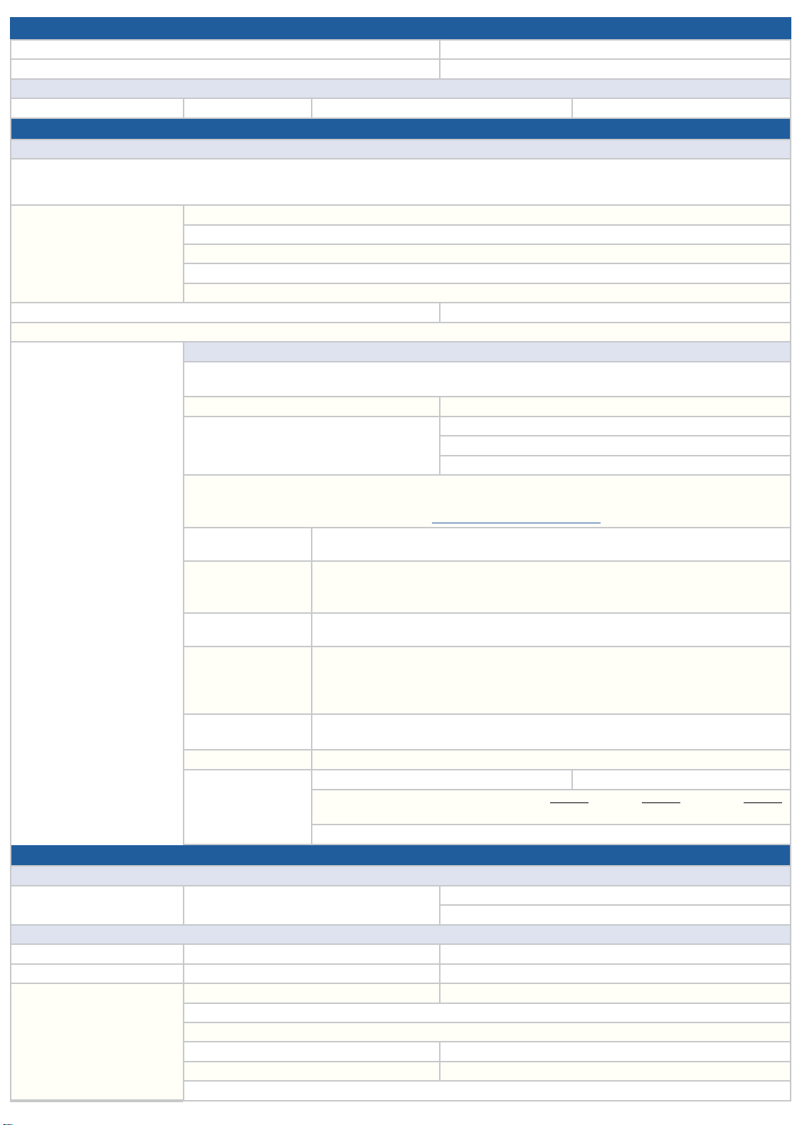
5.2. Customer Questionnaire
The following Questionnaires would help collecting information and, in some cases,
address customer concerns with the Cockpit Gen1 (CP1) Gen4 infotainment system.
Please complete as much information as possible in as much detail as possible
following the format of the questionnaire. Please use a separate questionnaire for
each concern. There is a general questionnaire to capture the details for any concern.
However, we have also prepared a questionnaire specific to a category: Audio Output,
Navigation Operation, Bluetooth Operation, Apple CarPlay Operation, Android Auto
Operation, USB Port. Please use customer questionnaires, because they have concern
specific questions.
NOTE: Some of these questions will require the Technician to provide detailed
feedback, while the system is experiencing the concern. Others will require specific
information from the customer. In all cases, the Questionnaire Pages should be
completed at the time of write-up to gather as much detail from the customer as
possible. Always request and retain any pictures or videos (preferred) of the condition
and any data gathered from the system. Once the form is completed, it may be
attached to QMR, emailed to
[email protected] (This is not an interactive mailbox.
It only receives the completed forms) or faxed to (856)-254-1305.
If the condition can be duplicated, try to gather as much information as possible
regarding the steps required to recreate the issue.
For example:
1. Unlock car
2. Start engine
3. Shift to reverse while the “STARLINK” screen is displayed. FM audio is playing in
the background
4. Connect an iPhone via USB hub for CarPlay
5. Shift to drive
...and so on. This information helps with being able to investigate the issue.
62
Page 63
GENERAL
1a. Date of Service: 1b. Reoccurring problem: YES NO
2a. Original Date of Service (if applicable): 2b. Total number of visits:
Vehicle Details
4a. Vehicle Model: 4b.Year: 4c. Mileage: 4d. VIN:
A. Customer Interview Details
Condition Description
7. Condition Description Summary (per customer) please supply video or photo, if possible:
Step 1:
8. Last 5 actions performed
before symptom occurred
(List 1 to 5 in order)
9. Incident Date and Time: Cabin temperature:
10. Can duplicate Customer’s Complaint (please supply video or photo, if possible): YES NO
Condition when issue observed: Driving Mode (indicate where applies)
Step 2:
Step 3:
Step 4:
Step 5:
11. PARKED: Accessory On: YES NO Ignition On: YES NO
DRIVING: YES NO
12a. Error Message displayed: YES NO 12b. If YES, what is the content?
13a. Any Genuine Subaru or aftermarket accessories
installed?
14. If the phones or other devices paired/connected to the unit, what type of phone/software/cell phone carrier (List all the data)?
13b. List cables used, if any:
13c. Genuine cables: YES NO
13d. No physical damage: YES NO
NOTE: To verify if a compatible phone follow this link:
15. Display/touch switch
malfunction
16. Operating problems
17. Radio malfunction
18. Audio malfunction
19. CD/USB/SD/iPod
malfunction
20. Voice Recognition
21. HVAC controls 21a. HVAC control screen displayed? YES NO 21b. HVAC controls work? YES NO
Brightness / Contrast: Discoloration: No rear camera: Partial Display:
Lines in screen: No Audio Control Screen: No Navi Map on Screen: Others:
Display does not switch: Display changes unexpectedly: Response is dull/slow:
Does not respond to key entry: Does not respond to steering switch entry:
Does not change to night mode screen: Discs cannot be inserted or ejected: Others:
AM Station: FM Station: SXM Station: HD Station: No Sound:
No/Poor Sound: Noise /Static: Sound cuts in/out: Others:
Does not sound: Front R: Front L: Rear R: Rear L: Others:
Operation related problems: Cannot adjust volume level:
Cannot use tone control or adjust tone range: Cannot record: Sound skipping:
CD: DVD: Specific mode/disc: Others:
Will not accept: Will no eject (CD): Will not play: Skips/Jump Chapter: No Sound:
Noise/Static: Sound cuts in/out: Shows Error: Others:
Voice recognition is not ready: Not recognize commands: Others:
21c. If NO, which operation doesn’t work? ON/OFF:
21d. Brief description of condition:
http://www.subaru.com/owners/index
MODE SETTING: Auto: Recirculation:
B. For Retailer Personnel
Retailer Details
22a. Retailer Name: 22b. Retailer Code or Acct#: 22c. Contact Name:
22d. Phone:
Hardware Component Details (as applicable):
Cockpit Control Unit (CCU) 23a. SW Ver: 23b. Part Number:
Center Information Display (CID) 24a. SW Ver: 24b. Part Number:
Summary for Diagnostics
performed:
25a. Have any DTCs been set? YES NO 25b. If YES, list all:
26. All CP1 wiring harness connectors fully seated in the unit? YES NO
27. Is there any physical damage/tampering present? YES NO
28a. Has the video been taken? YES NO 28b. If YES, has it been shared? YES NO
29a. Has the data log been collected? YES NO 29b. If YES, has it been shared? YES NO
30. Have you checked the Service Manual? YES NO
Fan speed: Temp setting:
63
Page 64
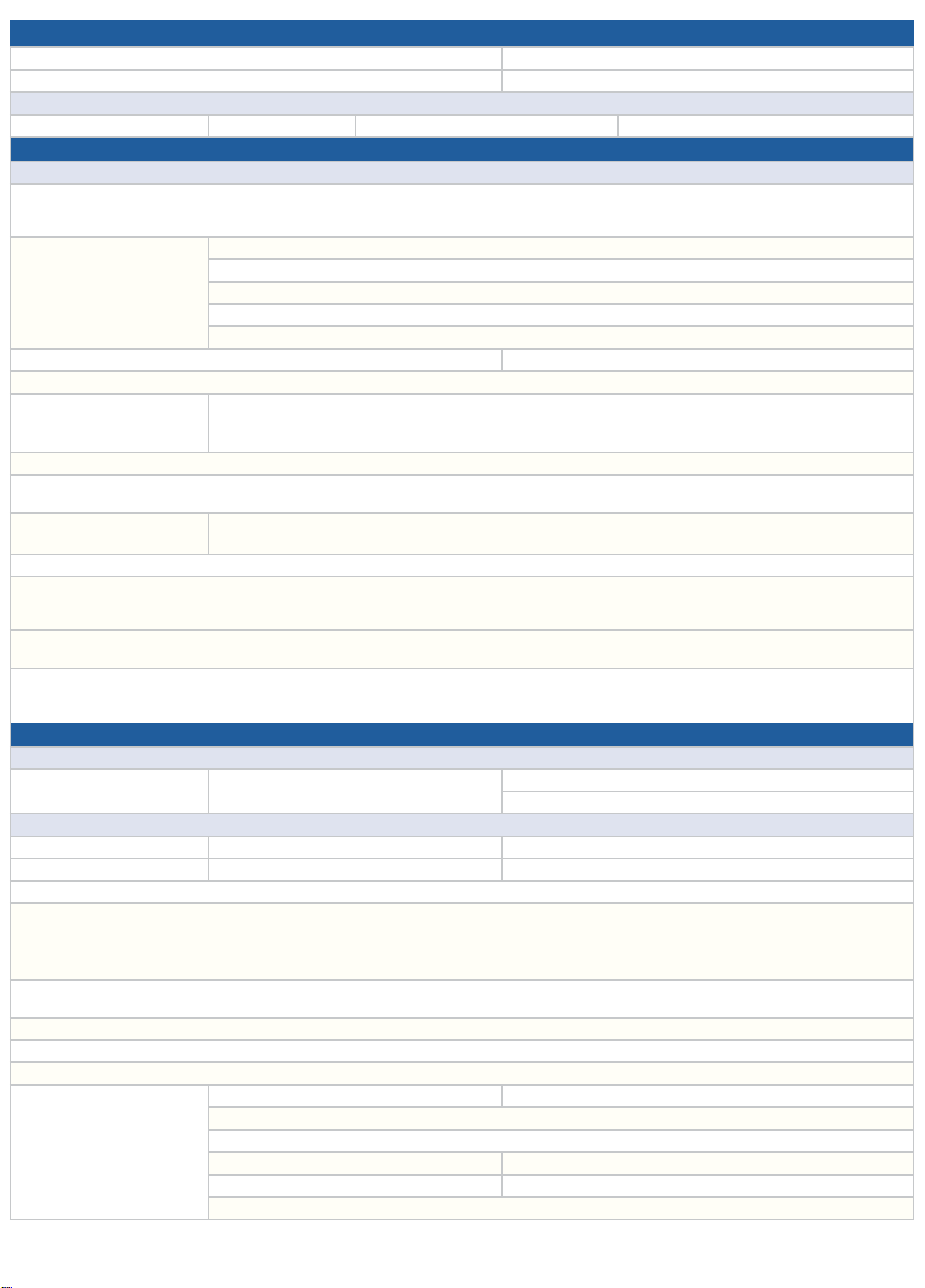
AUDIO OUTPUT CONCERN
1a. Date of Service: 1b. Reoccurring problem: YES NO
2a. Original Date of Service (if applicable): 2b. Total number of visits:
Vehicle Details
3a. Vehicle Model: 3b.Year: 3c. Mileage: 3d. VIN:
A. Customer Interview Details
Condition Description
4. Condition Description Summary (per customer) please supply video or photo, if possible:
Step 1:
5. Last 5 actions performed
before symptom occurred
(List 1 to 5 in order)
6a. Incident Date and Time: 6b. Cabin temperature:
7. Can duplicate Customer’s Complaint (please supply video or photo, if possible): YES NO
8. Audio malfunction
9. What audio source is the Head Unit on when the concern occurs from: (AM, FM, SXM, Carplay etc.)
10. For tuner - related issues (AM/FM/SXM/DAB Digital Audio Broadcasting), is the concern on a specific frequency/ channel?
Please list the frequencies/channels here:
11. Radio malfunction
12. For media (USB, BTSA Bluetooth Streaming Audio, CD, etc), list the devices used, file type (mp3, mp4, cda, aac, etc).
13. Is the concern heard in each audio channel? YES NO
Adjust balance and fade to confirm. (Balance and fade can be adjusted by going to Home Screen -> Settings -> Sound -> Audio -> Sound Customization . Drag the
crosshair to each corner of the vehicle to check for output from each audio channel.)
14. Turning the volume knob would display the volume indicator on the center display? YES NO
Pressing steering wheel volume switch would display the volume indicator in the combination meter display YES NO
15. Does the system show indication when playback is occurring? YES NO
For example, if using a media device (CD, iPod, USB, etc), does the playback timer update? YES NO
If using tuner (AM, FM, SXM), is there station data displayed and is it updating? YES NO
B. For Retailer Personnel
16a. Retailer Name: 16b. Retailer Code or Acct#: 16c. Contact Name:
Cockpit Control Unit (CCU) 17a. SW Ver: 17b. Part Number:
Center Information Display (CID) 18a. SW Ver: 18b. Part Number:
19. For volume/audio concerns - Has the amplifier been checked and proper operation confirmed? YES NO
20. Is vehicle equipped with an external amplifier? YES NO Brand Name: Part Number:
If YES, confirm connections are proper between head unit and amplifier.
If YES, does disconnecting and reconnecting the amplifier address the concern? YES NO
If YES, does disconnecting and reconnecting the CCU address the concern? YES NO
21. Perform a swap of each component with a known good amplifier and CCU. Swap the amplifier first, then check if the concern is addressed.
If the condition persists, swap the CCU. Was the concern addressed by swapping one (or both) of the components? YES NO
22. Can the concern be only observed while listening to certain audio channel(s)? YES NO
23. Have you confirmed connections from head unit to speakers are not damaged? YES NO
24. If the vehicle comes equipped with an Harman/Kardon amplifier, have you confirmed connections between amplifier and speakers are not damaged? YES NO
Summary for Diagnostics
performed:
Step 2:
Step 3:
Step 4:
Step 5:
Does not sound: Front R: Front L: Rear R: Rear L: Others: Operation related problems:
Cannot adjust volume level: Cannot use tone control or adjust tone range: Cannot record: Sound skipping:
CD: DVD: Specific mode/disc: Others:
AM Station: FM Station: SXM Station: HD Station: No Sound:
No/Poor Sound: Noise /Static: Sound cuts in/out: Others:
Retailer Details
16d. Phone:
Hardware Component Details (as applicable):
25a. Have any DTCs been set? YES NO 25b. If YES, list all:
26. All CP1 wiring harness connectors fully seated in the unit? YES NO
27. Is there any physical damage/tampering present? YES NO
28a. Has the video been taken? YES NO 28b. If YES, has it been shared? YES NO
29a. Has the data log been collected? YES NO 29b. If YES, has it been shared? YES NO
30. Have you checked the Service Manual? YES NO
64
Page 65
NAVIGATION OPERATION CONCERN
1a. Date of Service: 1b. Reoccurring problem: YES NO
2a. Original Date of Service (if applicable): 2b. Total number of visits:
Vehicle Details
3a. Vehicle Model: 3b.Year: 3c. Mileage: 3d. VIN:
A. Customer Interview Details
Condition Description
4. Condition Description Summary (per customer) please supply video or photo, if possible:
Step 1:
5. Last 5 actions performed
before symptom occurred
(List 1 to 5 in order)
6a. Incident Date and Time: 6b. Cabin temperature:
7. Can duplicate Customer’s Complaint (please supply video or photo, if possible): YES NO
8a. Error Message displayed? YES NO 8b. If YES, what is the content?
9. Fault in navigation system
10a. Is the concern observed in a specific location? YES NO
Step 2:
Step 3:
Step 4:
Step 5:
Cursor or map rotating: Wrong location of vehicle: Cursor hopping during driving: Map image incomplete:
No GPS marks displayed: Incorrect time display: Guide not initiated: No route search:
Caution remains on navigation screen: Unexpected return back to opening screen: No voice guidance:
Guidance volume too low: Will not read data: Will not update: Destination/route problem:
Display does not change(frozen): Overall navi operation slow: No GPS reception: Others:
10b. If YES, please provide an exact address or multiple addresses as applicable.
11. Is the cocern related to Voice Recognition operation? YES NO
If YES, have you confirmed the same address could be entered by typing? YES NO
If YES, have you confirmed Voice Recognition operation is not impacted by the microphone operation? YES NO
If YES, have you confirmed the customer is following recommendations outlined in the Owner’s Manual for optimizing Voice Recognition feature? YES NO
B. For Retailer Personnel
Retailer Details
12a. Retailer Name: 12b. Retailer Code or Acct#: 12c. Contact Name:
12d. Phone:
Hardware Component Details (as applicable):
Cockpit Control Unit (CCU) 13a. SW Ver: 13b. Part Number:
Center Information Display (CID) 14a. SW Ver: 14b. Part Number:
Summary for Diagnostics
performed:
15a. Have any DTCs been set? YES NO 15b. If YES, list all:
16. All CP1 wiring harness connectors fully seated in the unit? YES NO
17. Is there any physical damage/tampering present? YES NO
18a. Has the video been taken? YES NO 18b. If YES, has it been shared? YES NO
19a. Has the data log been collected? YES NO 19b. If YES, has it been shared? YES NO
20. Have you checked the Service Manual? YES NO
65
Page 66
BLUETOOTH OPERATION CONCERN
1a. Date of Service: 1b. Reoccurring problem: YES NO
2a. Original Date of Service (if applicable): 2b. Total number of visits:
Vehicle Details
3a. Vehicle Model: 3b.Year: 3c. Mileage: 3d. VIN:
A. Customer Interview Details
Condition Description
4. Condition Description Summary (per customer) please supply video or photo, if possible:
Step 1:
5. Last 5 actions performed
before symptom occurred
(List 1 to 5 in order)
6a. Incident Date and Time: 6b. Cabin temperature:
7. Can duplicate Customer’s Complaint (please supply video or photo, if possible): YES NO
8. List after market products used, if any: 8a. List after market cables used, if any:
9. Bluetooth Audio related
malfunction
10. Bluetooth handsfree related
malfunction
11. Is the connection made at the start up? YES NO
If YES, is the connection dropped at some other point of operation? YES NO
If NO, Other (List):
12. What type of phone/software/cell phone carrier (List all the data)?
Step 2:
Step 3:
Step 4:
Step 5:
8b. No physical damage: YES NO
Will no pair: Will not play: No sound: Noise/static: Disconnect on its own: Others:
Will not pair: Cannot hear (Receiver): Cannot hear (Caller): Sounds Garbled: Address book will not transfer:
Disconnect on its own:
NOTE: To verify if a compatible phone follow this link:
13. Is the device still paired to the Head Unit? YES NO
Confirm the device is in the paired device list located under Home Screen -> Settings -> Phone -> Manage Devices.
14. Is the vehicle system still listed as a paired device on the phone? YES NO
15. Can the phone be manually reconnected through the phone settings menu? YES NO
Follow this path Home -> Settings -> Phone -> Manage Devices, then select the paired phone and select Connect.
16. Have you confirmed a similar model phone or phones reproduces the same concern? YES NO
17. For issues with Bluetooth, Phonebook, or SMS sync please answer the questions below.
Was the phonebook/SMS access request granted when phone was paired to the vehicle? YES NO
Was the prompt accepted on the phone? YES NO
Was the phonebook download option enabled in the CP1 settings? YES NO
http://www.subaru.com/owners/index
B. For Retailer Personnel
Retailer Details
18a. Retailer Name: 18b. Retailer Code or Acct#: 18c. Contact Name:
18d. Phone:
Hardware Component Details (as applicable):
Cockpit Control Unit (CCU) 19a. SW Ver: 19b. Part Number:
Center Information Display (CID) 20a. SW Ver: 20b. Part Number:
Summary for Diagnostics
performed:
21a. Have any DTCs been set? YES NO 21b. If YES, list all:
22. All CP1 wiring harness connectors fully seated in the unit? YES NO
23. Is there any physical damage/tampering present? YES NO
24a. Has the video been taken? YES NO 24b. If YES, has it been shared? YES NO
25a. Has the data log been collected? YES NO 25b. If YES, has it been shared? YES NO
26. Have you checked the Service Manual? YES NO
66
Page 67
APPLE CARPLAY CONCERN
1a. Date of Service: 1b. Reoccurring problem: YES NO
2a. Original Date of Service (if applicable): 2b. Total number of visits:
Vehicle Details
3a. Vehicle Model: 3b.Year: 3c. Mileage: 3d. VIN:
A. Customer Interview Details
Condition Description
4. Condition Description Summary (per customer) please supply video or photo, if possible:
Step 1:
5. Last 5 actions performed
before symptom occurred
(List 1 to 5 in order)
6a. Incident Date and Time: 6b. Cabin temperature:
7. Can duplicate Customer’s Complaint (please supply video or photo, if possible): YES NO
8. Verified the USB cable used is certified Apple cable and is not damaged? YES NO
If YES, have you tried another cable? YES NO
No physical damage: YES NO
9. Have you verified, if the phone is compatible per the link: http://www.subaru.com/owners/index? YES NO
10. Did you confirm CarPlay to be enabled without any restrictions on the phone? YES NO
11. Did you verify the phone OS version to be up to date and the app (CarPlay) is up to date? YES NO
Please note make, model, version number of the device and the app, service provider.
Device Make: Device Model: Device Software Version:
App Name App Version: Cell Provider (if applicable):
12. Try a similar device, does the issue still occur? YES NO
Please note version number of the device and the app. Device Software Version: App Name App Version:
13. Voice recognition malfunction
14. If applicable, have you confirmed the same issue (example: handsfree calling, streaming, voice recognition etc.) is duplicated when the phone is only paired via
Bluetooth and not connected via USB cable? YES NO
15. Is there an evidence the phone is charging, when connected via USB cable? YES NO
B. For Retailer Personnel
16a. Retailer Name: 16b. Retailer Code or Acct#: 16c. Contact Name:
17a. Vehicle Model: 17b.Year: 17c. Mileage: 17d. VIN:
Cockpit Control Unit (CCU) 18a. SW Ver: 18b. Part Number:
Center Information Display (CID) 19a. SW Ver: 19b. Part Number:
20. Have you tested the customer’s phone with a known good vehicle? YES NO
If the application launches successfully, swap USB hub cable then USB hub if necessary. If the issue still persists, try swapping the CCU.
Was the concern addressed by addressing one or more of these components? YES NO
If so, request exchange of suspect component
Summary for Diagnostics
performed:
Step 2:
Step 3:
Step 4:
Step 5:
Voice recognition is not ready: Not recognize commands: Other:
Retailer Details
16d. Phone:
Vehicle Details
Hardware Component Details (as applicable):
21a. Have any DTCs been set? YES NO 21b. If YES, list all:
22. All CP1 wiring harness connectors fully seated in the unit? YES NO
23. Is there any physical damage/tampering present? YES NO
24a. Has the video been taken? YES NO 24b. If YES, has it been shared? YES NO
25a. Has the data log been collected? YES NO 25b. If YES, has it been shared? YES NO
26. Have you checked the Service Manual? YES NO
67
Page 68
ANDROID AUTO CONCERN
1a. Date of Service: 1b. Reoccurring problem: YES NO
2a. Original Date of Service (if applicable): 2b. Total number of visits:
Vehicle Details
3a. Vehicle Model: 3b.Year: 3c. Mileage: 3d. VIN:
A. Customer Interview Details
Condition Description
4. Condition Description Summary (per customer) please supply video or photo, if possible:
Step 1:
5. Last 5 actions performed
before symptom occurred
(List 1 to 5 in order)
6a. Incident Date and Time: 6b. Cabin temperature:
7. Can duplicate Customer’s Complaint (please supply video or photo, if possible): YES NO
8a. Error Message displayed? YES NO 8b. If YES, what is the content?
9. Verified the USB cable used is genuine cable and is not damaged? YES NO
If yes, have you tried another cable? YES NO
No physical damage: YES NO
10. Have you verified, if the phone is compatible per the link: http://www.subaru.com/owners/index? YES NO
11. Did you confirm Android Auto to be enabled without any restrictions on the phone? YES NO
12. Did you verify the phone OS version to be up to date and the app (Android Auto) is up to date? YES NO
Please note make, model, version number of the device and the app, service provider.
Device Make: Device Model: Device Software Version:
App Name App Version: Cell Provider (if applicable):
13. Try a similar device, does the issue still occur? YES NO
Please note version number of the device and the app. Device Software Version: App Name App Version:
14. Voice recognition malfunction
15. If applicable, have you confirmed the same issue (example: handsfree calling, streaming, voice recognition etc.) is duplicated when the phone is only paired via
Bluetooth and not connected via USB cable? YES NO
16. Is there an evidence the phone is charging, when connected via USB cable? YES NO
B. For Retailer Personnel
17a. Retailer Name: 17b. Retailer Code or Acct#: 17c. Contact Name:
Cockpit Control Unit (CCU) 18a. SW Ver: 18b. Part Number:
Center Information Display (CID) 19a. SW Ver: 19b. Part Number:
20. Have you tested the customer’s phone with a known good vehicle? YES NO
If the application launches successfully, swap USB hub cable then USB hub if necessary. If the issue still persists, try swapping the CCU.
Was the concern addressed by addressing one or more of these components? YES NO
If so, request exchange of suspect component
Summary for Diagnostics
performed:
Step 2:
Step 3:
Step 4:
Step 5:
Voice recognition is not ready: Not recognize commands: Other:
Retailer Details
17d. Phone:
Hardware Component Details (as applicable):
21a. Have any DTCs been set? YES NO 21b. If YES, list all:
22. All CP1 wiring harness connectors fully seated in the unit? YES NO
23. Is there any physical damage/tampering present? YES NO
24a. Has the video been taken? YES NO 24b. If YES, has it been shared? YES NO
25a. Has the data log been collected? YES NO 25b. If YES, has it been shared? YES NO
26. Have you checked the Service Manual? YES NO
68
Page 69
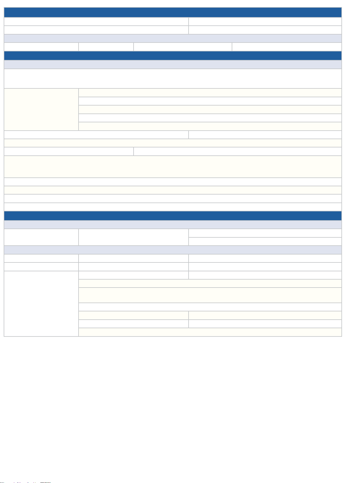
USB PORT CONCERN
1a. Date of Service: 1b. Reoccurring problem: YES NO
2a. Original Date of Service (if applicable): 2b. Total number of visits:
Vehicle Details
3a. Vehicle Model: 3b.Year: 3c. Mileage: 3d. VIN:
A. Customer Interview Details
Condition Description
4. Condition Description Summary (per customer) please supply video or photo, if possible:
Step 1:
5. Last 5 actions performed
before symptom occurred
(List 1 to 5 in order)
6a. Incident Date and Time: 6b. Cabin temperature:
7. Can duplicate Customer’s Complaint (please supply video or photo, if possible): YES NO
8a. Error Message displayed? YES NO 8b. If YES, what is the content?
9. Verified the USB cable used is genuine cable and is not damaged? YES NO
If yes, have you tried another cable? YES NO
No physical damage: YES NO
10. Is the USB connection identified in the Information bar area of CID? YES NO
11. Does the USB device work in a like vehicle? YES NO
12. Do other USB devices work in the suspect vehicle? YES NO
13. Is there an evidence the phone is charging, when connected via USB cable? YES NO
B. For Retailer Personnel
14a. Retailer Name: 14b. Retailer Code or Acct#: 14c. Contact Name:
Cockpit Control Unit (CCU) 15a. SW Ver: 15b. Part Number:
Center Information Display (CID) 16a. SW Ver: 16b. Part Number:
Summary for Diagnostics
performed:
Step 2:
Step 3:
Step 4:
Step 5:
Retailer Details
14d. Phone:
Hardware Component Details (as applicable):
17a. Have any DTCs been set? YES NO 17b. If YES, list all:
18. All CP1 wiring harness connectors fully seated in the unit? YES NO
19. Is the USB drive recognized in the connection check screen available via Dealership mode (Push the Tune knob six times, while
simultaneously pressing down on both sides of the passenger side A/C up/down switch)? YES NO
20. Is there any physical damage/tampering present? YES NO
21a. Has the video been taken? YES NO 21b. If YES, has it been shared? YES NO
22a. Has the data log been collected? YES NO 22b. If YES, has it been shared? YES NO
23. Have you checked the Service Manual? YES NO
69
Page 70
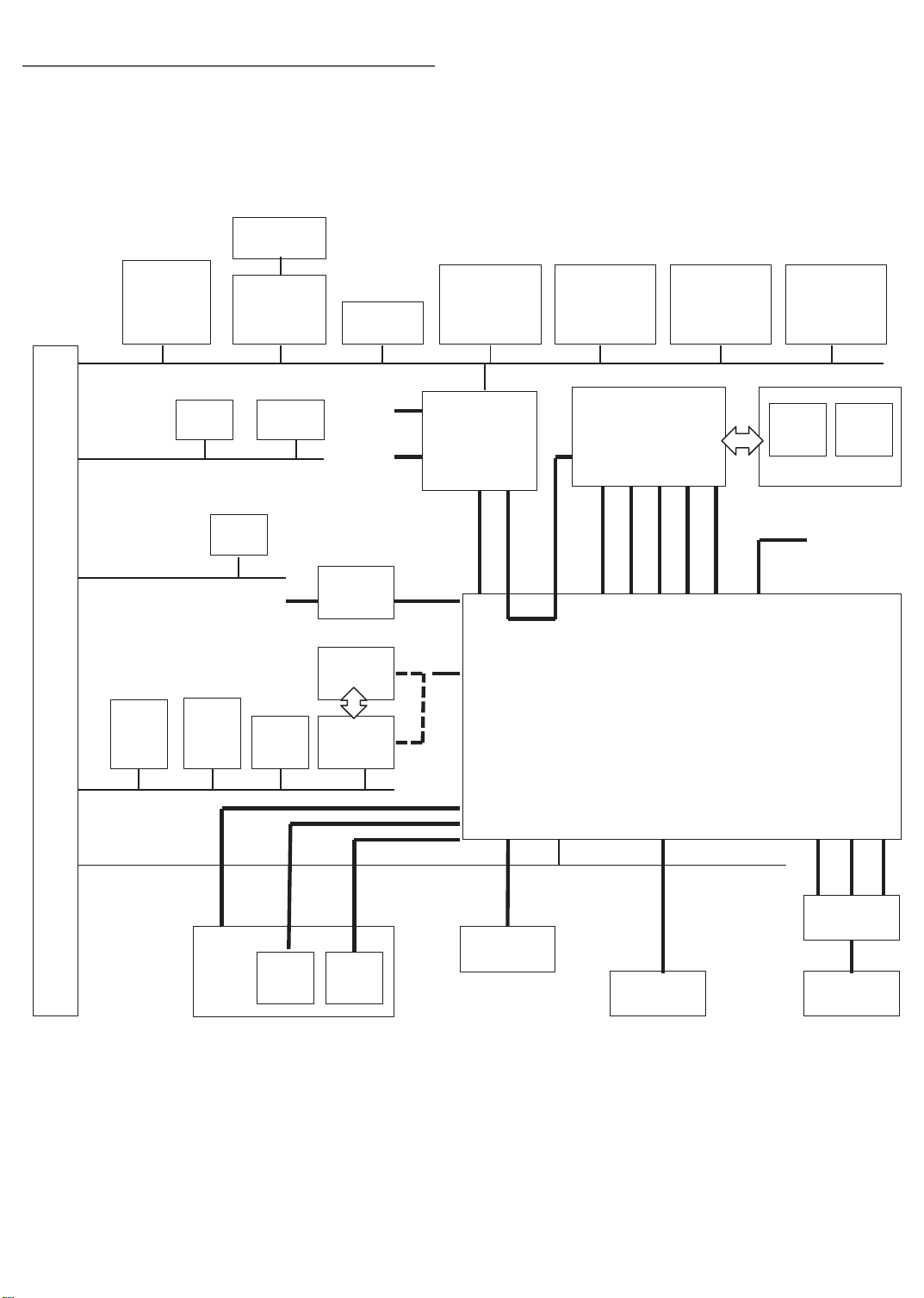
5.3. System diagram : CAN communication
70
Hazard
Central
Gateway
CU
Driver
Monitoring
Unit
Body
CAN
Chassis
CAN
Power Unit
CAN
Stereo
Camera
TPMS
CU
ECU
+B_backup
Radar
Sensor
LH
Body
Integration
Unit
VDC CU
RAB
CU
A/C CU
+B_
direct
IGN
CD
Rear
Camera
Camera
CU
Twin +
4.2inch TFT
Meter
LDVS
USB2.0
NTSC/
6.0V
Power
Rear gate
CU
UART
Power
Seat
CU
CID
(11.6inch)
LVDS
/RF
Wi-Fi
BT
Cockpit Control Unit
Outer
Mirror
CU LH
IGN
+B_backup
Headlamp
Automatic
Leveling LH
CID
(7inch)
+B_direct/
+B_backup
IGN/REV
With
CID
(7inch)
Advanced
Safety CAN
Outside
Connection
CAN
+B
AUX
Analog
Jack
Pin
USB2.0
USB
㽢2
Resistance
Division
Sterring
SW
Antenna
XM
RF RF +B
Antenna
AMP
Antenna
AM / FM
Page 71
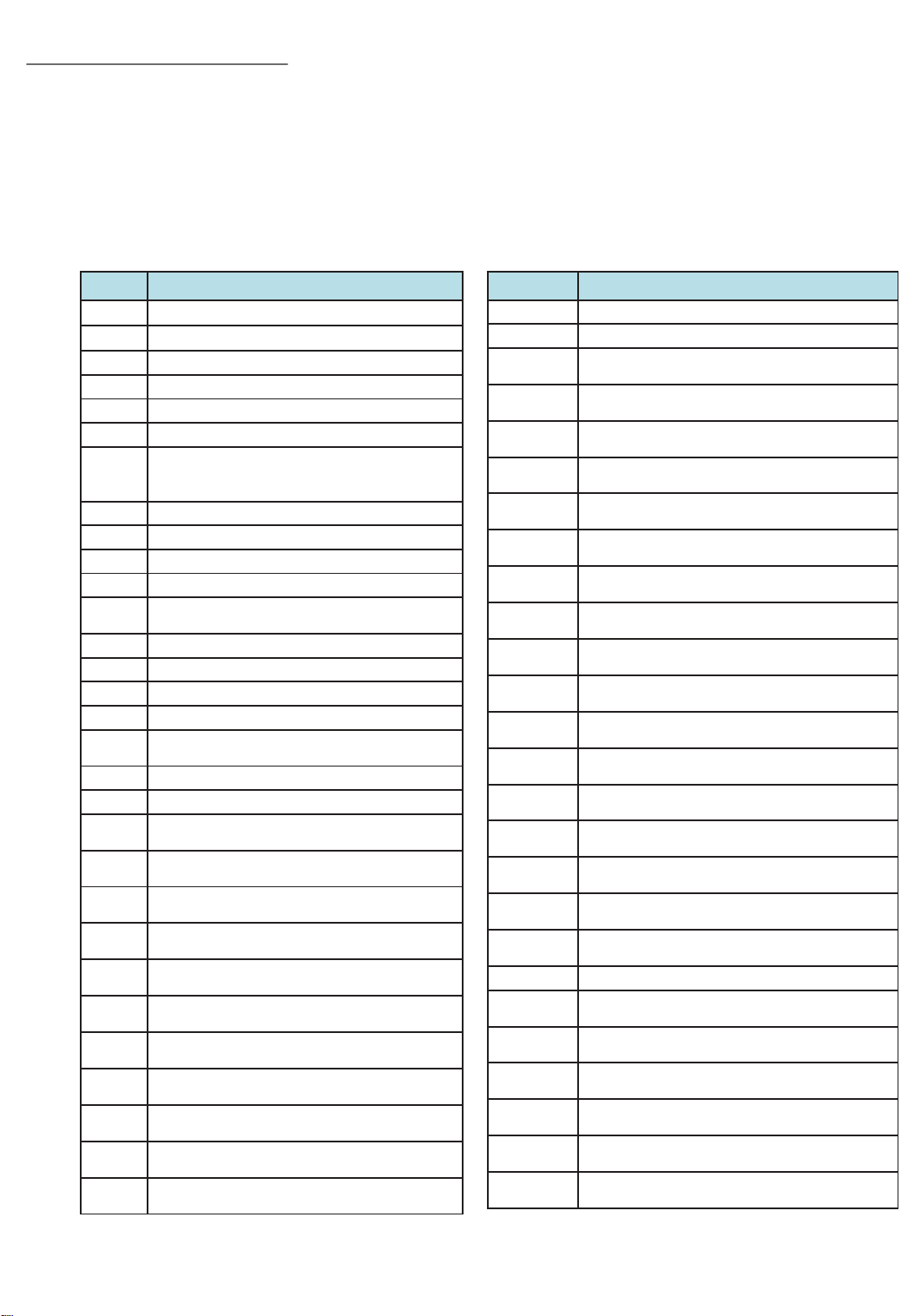
5.4 SUBARU Select Moniter
71
We can confirm the following items with Subaru selector monitor.
- DTC - Data Monitor
- Freeze Frame Data - Active Test㻌㻌
- Customaize - Work Support
5.4.1 DTC
DTC Contents
B2240
B2241
B2244
B2247
B2249
B224A
B224D
B2251
B2252
B2253
B2254
B2256
B2257
B2258
B2259
B225A
U007C
U0100
U0101
U0122
U0127
U0128
U0131
U0140
U0155
U0164
U0181
U0208
U0209
U0230
CAN COMMUNICATION (AUDIO) STUCK
CAN COMMUNICATION
AMPLIFIER COMMUNICATION
CD MECHANICAL
BLUETOOTH MODULE
BACKUP CAMERA
XM / SATELLITE DIGITAL AUDIO
RADIO SERVICE ANTENNA FAULTS
(SHORTED OR OPEN)
Amplifier abnormality (sky fault)
Amplifier abnormality (ground fault)
Amplifier abnormality (DC Offset)
GPS ANTENNA FAULTS
Data Communication Module
communication disconnection
Meter communication line abnormality
Meter signal input abnormality
CID communication abnormality
CID abnormality
CONTROL MODULE COMMUNICATION
BUS "BUS-J" OFF
LOST COMMUNICATION WITH ECM/PCM
LOST COMMUNICATION WITH TCM
LOST COMMUNICATION WITH
VEHICLE DYNAMICS CONTROL MODULE
LOST COMMUNICATION WITH
KEYLESS ENTRY CONTROL MODULE
LOST COMMUNICATION WITH
PARK BRAKE CONTROL MODULE
LOST COMMUNICATION WITH
POWER STEERING CONTROL MODULE
LOST COMMUNICATION WITH
BODY CONTROL MODULE
LOST COMMUNICATION WITH INSTRUMENT
PANEL CLUSTER (IPC) CONTROL MODULE
LOST COMMUNICATION WITH
HVAC CONTROL MODULE
LOST COMMUNICATION WITH
HEADLAMP LEVELING CONTROL MODULE
LOST COMMUNICATION WITH
SEAT MEMORY
LOST COMMUNICATION WITH
SEAT VENTILATION CONTROL MODULE
LOST COMMUNICATION WITH
POWER REAR GATE CONTROL MODULE
㻌
DTC Contents
U0401
U0402
U0416
U0417
U0420
U0422
U0423
U0424
U0430
U0482
U0509
U050A
U0531
U1120
U1140
U122E
U1232
U123A
U1265
U1283
U143A
U1469
U152F
U1533
U1566
U1584
INVALID DATA RECEIVED FROM ECM/PCM “A”
INVALID DATA RECEIVED FROM TCM
INVALID DATA RECEIVED FROM
VEHICLE DYNAMICS CONTROL MODULE
INVALID DATA RECEIVED FROM
PARK BRAKE CONTROL MODULE
INVALID DATA RECEIVED FROM
POWER STEERING CONTROL MODULE
INVALID DATA RECEIVED FROM
BODY CONTROL MODULE
INVALID DATA RECEIVED FROM
INSTRUMENT PANEL CLUSTER CONTROL MODULE
INVALID DATA RECEIVED FROM
HVAC CONTROL MODULE
INVALID DATA RECEIVED FROM
KEYLESS ENTRY CONTROL MODULE
INVALID DATA RECEIVED FROM
HEADLAMP LEVELING CONTROL MODULE
INVALID DATA RECEIVED FROM
SEAT MEMORY
INVALID DATA RECEIVED FROM
SEAT VENTILATION CONTROL MODULE
INVALID DATA RECEIVED FROM
POWER REAR GATE CONTROL MODULE
LOST COMMUNICATION WITH
AUTOSTART STOP CONTROL MODULE
LOST COMMUNICATION WITH
BODY CONTROL MODULE BODY-CAN
LOST COMMUNICATION WITH
DRIVER SIDE MIRROR CONTROL MODULE
LOST COMMUNICATION WITH
REAR/SIDE RADAR CONTROL MODULE
LOST COMMUNICATION WITH
DRIVER MONITORING SYSTEM
LOST COMMUNICATION WITH MULTI VIEW
SYSTEM
LOST COMMUNICATION WITH EyeSight "SA-BUS"
INVALID DATA RECEIVED FROM
DRIVER MONITORING SYSTEM
INVALID DATA RECEIVED FROM
AUTOSTART STOP CONTROL MODULE
INVALID DATA RECEIVED FROM
DRIVER SIDE MIRROR CONTROL MODULE
INVALID DATA RECEIVED FROM
REAR/SIDE RADAR CONTROL MODULE
INVALID DATA RECEIVED FROM
MULTI VIEW SYSTEM
INVALID DATA RECEIVED FROM
EyeSight "SA-BUS"
㻌
Page 72

5.4.2 Data Monitor, Freeze Frame Data
㻌
72
( Data Monitor ) Item
Trip Count
Count
Time Count
ACC Power connection state
IGN Power connection state
Reverse connection state
SPEED signal connection state
PKB connection state
Illumi connection state
XM ant connection state
GPS ant connection state
MIC connection state
Steering switch connection state
Rear camera connection state
USB1 connection state
CAN connection state
Steering Switch2 Connection State
BATT Voltage
BRIGHT Connection State
Speed Pluse Count
Speed
Driver's Door SW Connection State
Steering Angle Sensor Signal
BATT BackUp Voltage
Amplifier(Fabric) Connection State
Amplifier(Leather) Connection State
AMP(MUTE) Connection State
AMP(TX+) Connection State
AMP(TX-) Connection State
ANT-ON Input Value
DCM Connection State
Amplifier Type
Switch Detect (HARD)
Push SW Number (HARD)
Rotary Switch Check (Rightside Switch)
Rotary Switch Check (Leftside Switch)
Touch Switch Push Number Check
MIC1 Input Level Check
MIC2 Input Level Check
GPS Received Number
Global Positioning System Level
Time and Date Settings :Year
Time and Date Settings :Month
Time and Date Settings :Date
Time and Date Settings :Hour
Time and Date Settings :Minute
Time and Date Settings :Second
GPS Current Location; Latitude N/S
GPS Current Location; Latitude °
GPS Current Location; Latitude '
GPS Current Location; Latitude ''
GPS Current Location; Longitude E/W
GPS Current Location; Longitude °
GPS Current Location; Longitude '
GPS Current Location; Longitude ''
REAR SEAT entertainment
MVS camera connection state connection state
CID connection state
METER connection state
AUX BOX Stereo mini jack connection state
USB3 connection state
Gyro sensor relative direction
( FFD ) Item
䕿
䕿
䕿
䕿
䕿
䕿
䕿
䕿
䕿
䕿
䕿
䕿
䕿
䕿
䕿
䕿
䕿
䕿
䕿
䕿
䕿
䕿
䕿
䕿
䕿
䕿
䕿
䕿
䕿
䕿
䕿
Page 73
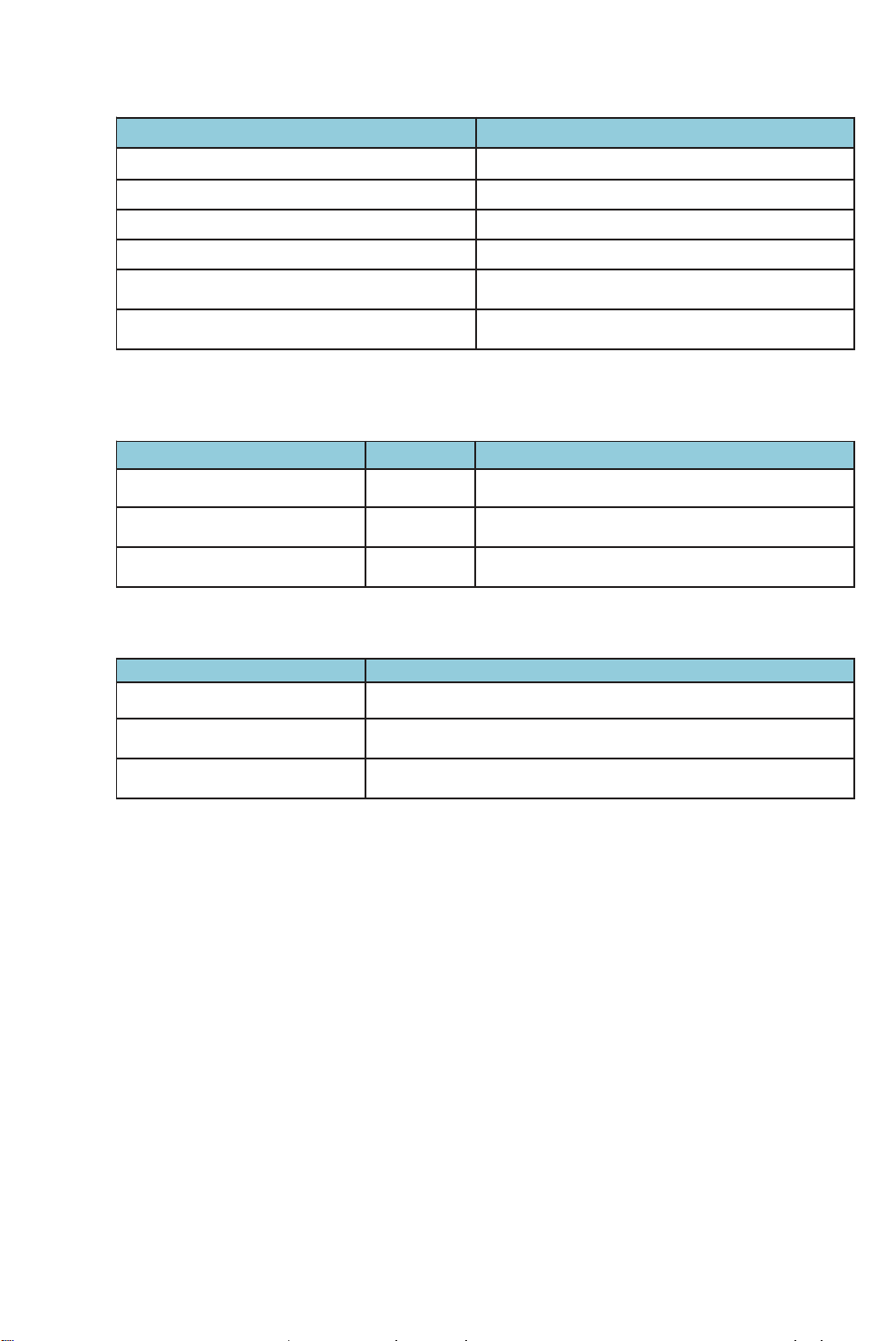
5.4.3 Active Test
73
FM SEEK UP/DOWN Check the FM SEEK operation.
AM SEEK UP/DOWN Check the AM SEEK operation.
Speaker Output Volume Adjustment Check the speaker output (sound volume) operation.
Speker Output Check Check speaker output.
Item Contents
Speker Output Check(Harman/Kardon speaker
Diag Recorder Data Delete Initialize the log for manufacturer’s analysis.
5.4.4 Customaize
Camera Guide Line Settings ON
Camera Caution Display Settings ON Set warning indicator display.
Diag Recorder Settings ON Software debug analysis (for analysis by manufacturer)
5.4.5 Work Support
ECU Parts Number Display item number of the audio or navigation.
Software information Software information is displayed.
Memory Initialization Reset to the factory settings.
䠅
Item Initial setting Contents
Item Contents
Check speaker output. (Harman/Kardon speaker
Set guide line display.
䠅
Page 74
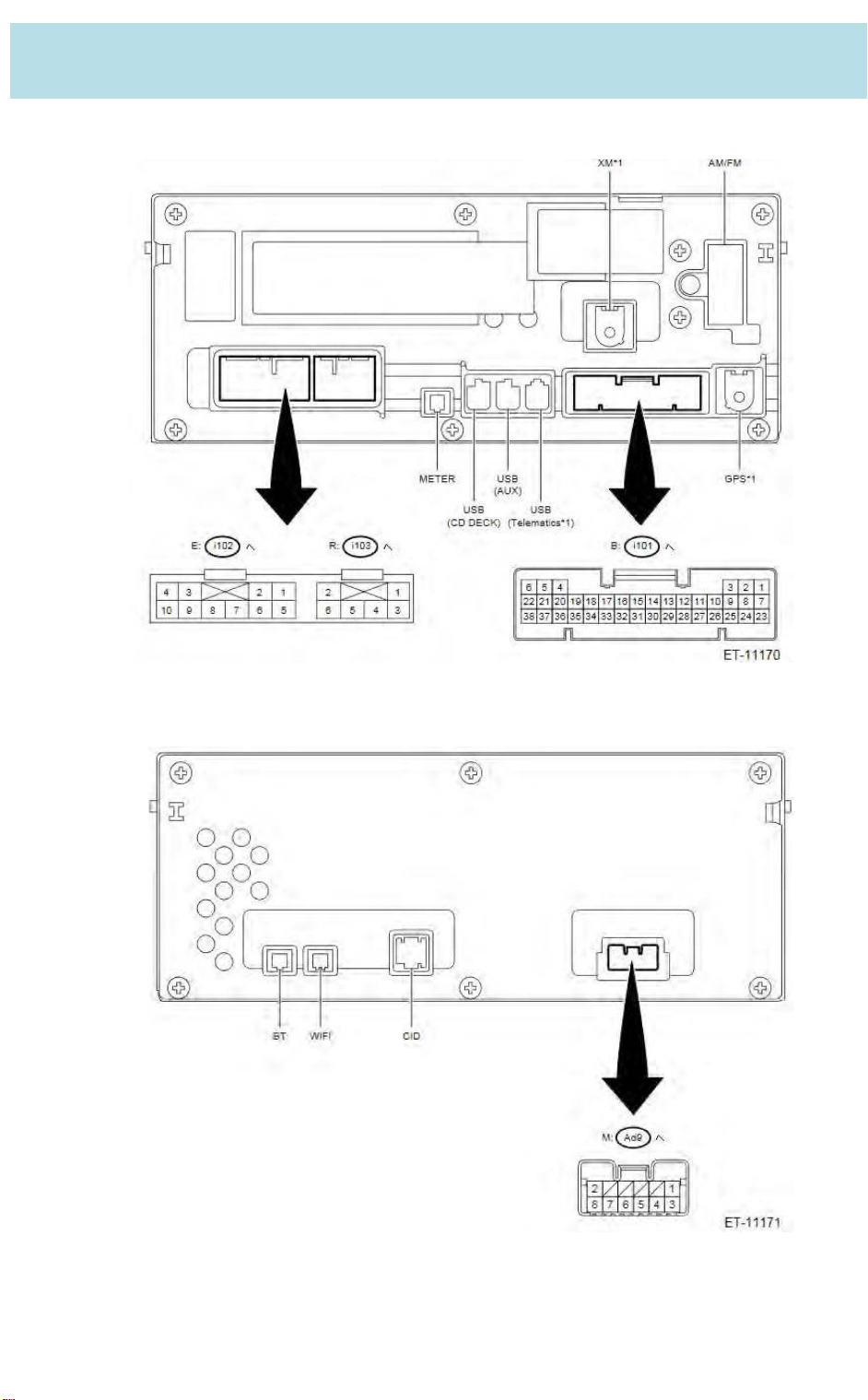
6. I/O Signal
74
(1) CCU
䙟 Vehicle side
* The numbers indicate the pin numbers.
䙟 Center Information Display side
* The numbers indicate the pin numbers.
Page 75
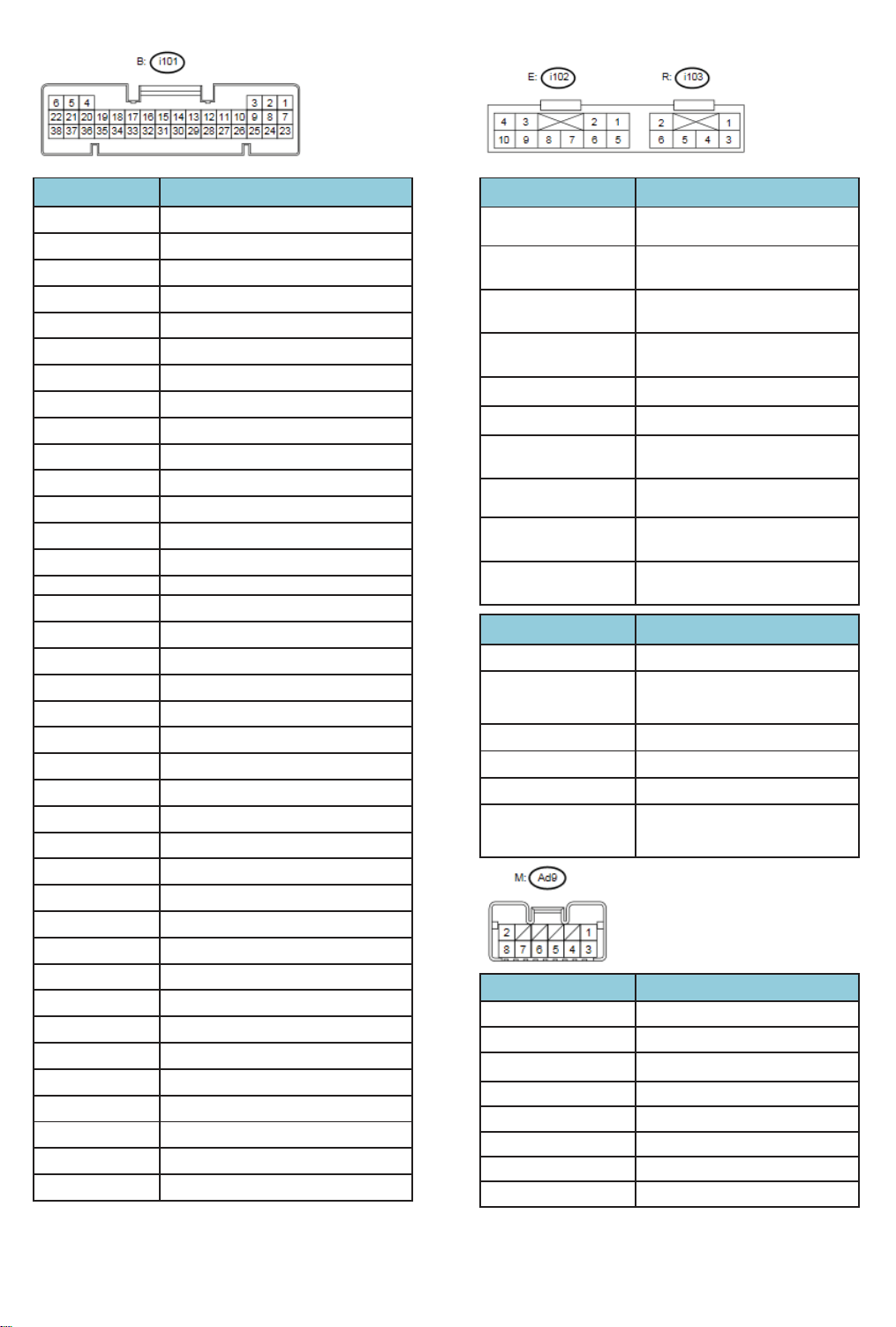
Terminal No. Contents
75
(i101) No. 1 —
(i101) No. 2 —
(i101) No. 3 —
(i101) No. 4 USB GND
(i101) No. 5 UART 2
(i101) No. 6 USB +B
(i101) No. 7 —
(i101) No. 8 REVERSE
(i101) No. 9 STEERING SWITCH1 (+)
(i101) No. 10 STEERING SWITCH2 (+)
(i101) No. 11 —
(i101) No. 12 STEERING SWITCH GND
(i101) No. 13 AMP MUTE
(i101) No. 14 CAN2 (H)
(i101) No. 15 CAN2 (L)
(i101) No. 16 MIC SLD
(i101) No. 17 MIC1 (+)
(i101) No. 18 MIC1 (о)
(i101) No. 19 MIC DET
(i101) No. 20 MIC2 (+)
(i101) No. 21 MIC2 (о)
(i101) No. 22 MIC power supply
(i101) No. 23 —
(i101) No. 24 —
(i101) No. 25 —
(i101) No. 26 GND ( Camera )
(i101) No. 27 6V+ ( Camera )
(i101) No. 28 CA+ ( Camera )
(i101) No. 29 CAо ( Camera )
(i101) No. 30 CAN1 (H)
(i101) No. 31 CAN1 (L)
(i101) No. 32 AUX GND
(i101) No. 33 Right AUX Input
(i101) No. 34 Left AUX Input
(i101) No. 35 Pin jack plugging detection
(i101) No. 36 —
(i101) No. 37 —
(i101) No. 38 DCM MUTE
Terminal No. Contents
(i102) No. 1 Right front door speaker (+)
(i102) No. 2 Left front door speaker (+)
(i102) No. 3
іїChassis GND
(i102) No. 4
іїChassis GND
(i102) No. 5 Right front door speaker (о)
(i102) No. 6 Left Front door speaker (о)
(i102) No. 7
іїChassis GND
(i102) No. 8 Antenna power supply
(i102) No. 9
іїChassis GND
(i102) No. 10 ILL(+)
Terminal No. Contents
(i103) No. 1 Right rear door speaker(+)
(i103) No. 2
(i103) No. 3 Right rear door speaker(о)
(i103) No. 4 SLD2
(i103) No. 5 ILL (о)
(i103) No. 6
Terminal No. Contents
(Ad9) No. 1
(Ad9) No. 2 CID GND
(Ad9) No. 3 CID IGN
(Ad9) No. 4 CID ILL (+)
(Ad9) No. 5 CID ILL(о)
(Ad9) No. 6 —
(Ad9) No. 7 —
(Ad9) No. 8 CID UART 2
IGN
Backup power supply
GND
BATT
Left rear door speaker(+) ,
or Interrupt audio (+)
Left rear door speaker(о) ,
or Interrupt audio (о)
CID power supply
Page 76
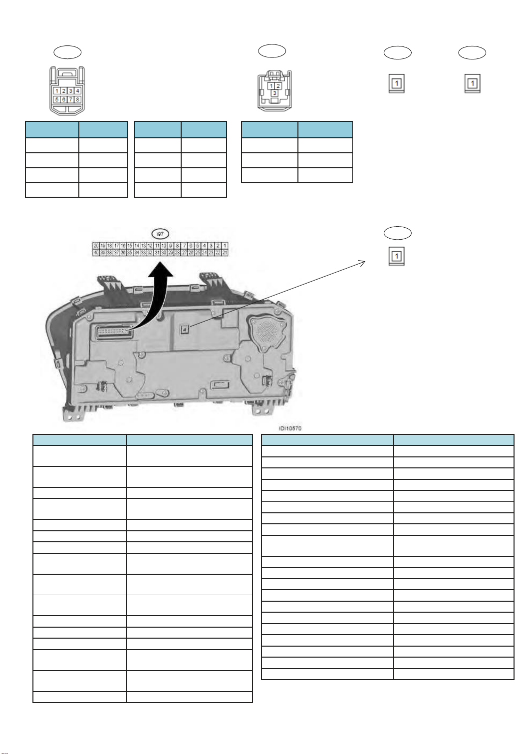
(2) CID
76
A
Ad11
B
Ad12
C
Ad13
D
Ad14
Terminal No. Contents
(Ad11) No. 1
(Ad11) No. 2 —
(iAd11) No. 3 ILL+
(Ad11) No. 4 +B BACKUP
UART2
(3) Meter
Terminal No. Contents
(Ad11) No. 5 GND
(Ad11) No. 6 —
(Ad11) No. 7 ILL-
(Ad11) No. 8 ING
Terminal No. Contents
(Ad12) No. 1 CID DATA+
(Ad12) No. 2 CID DATA-
(Ad12) No. 3 CID GND
Wifi Bluetooth
D
Ad4
Meter Data
Terminal No. Contents
(i97) No. 1(+) ії
Chassis GND (о)
(i97) No. 2(+) ії
Chassis GND (о)
(i97) No. 3 —
(i97) No. 4(+)ії
Chassis GND (о)
(i97) No. 5 —
(i97) No. 6 CAN H
(i97) No. 7 CAN L
(i97) No. 8(+)ії
Chassis GND (о)
(i97) No. 9(+)ії
Chassis GND (о))
(i97) No. 10(+)ії
Chassis GND (о)
(i97) No. 11 —
(i97) No. 12 U-ART2
(i97) No. 13㻌- 17 Not connected
(i97) No. 18(+)ії
Chassis GND (о)
(i97) No. 19(+)ії
Chassis GND (о)
(i97) No. 20 —
Battery power supply
Ignition power supply (main)
Seat belt (driver’s seat)
Seat belt 䠄Rear seat right
Seat belt 䠄center seat
Seat belt 䠄Rear seat left
Oil pressure warning light
Security indicator
Terminal No. Contents
(i97) No. 21 RH turn indicator
(i97) No. 22 LH turn indicator
(i97) No. 23 Ambient sensor (+)
(i97) No. 24 Ambient sensor (о)
(i97) No. 25 Fuel level sensor (+)
(i97) No. 26 Fuel level sensor (-)
(i97) No. 27 U-ART3
(i97) No. 28 —
(i97) No. 29
䠅
䠅
䠅
(i97) No. 30 Illumination control switch (VR)
(i97) No. 31 Illumination control switch (+)
(i97) No. 32іїNo. 29 Bright switch signal input
(i97) No. 33 Bright switch signal output
(i97) No. 34 Illumination. (о) PWM
(i97) No. 35 SI-DRIVE switch
(i97) No. 36 —
(i97) No. 37 —
(i97) No. 38іїChassis GND (о) TFT switch
(i97) No. 39 —
(i97) No. 40іїChassis GND (о) GND
Illumination control switch
(GND)
Page 77

77
Page 78
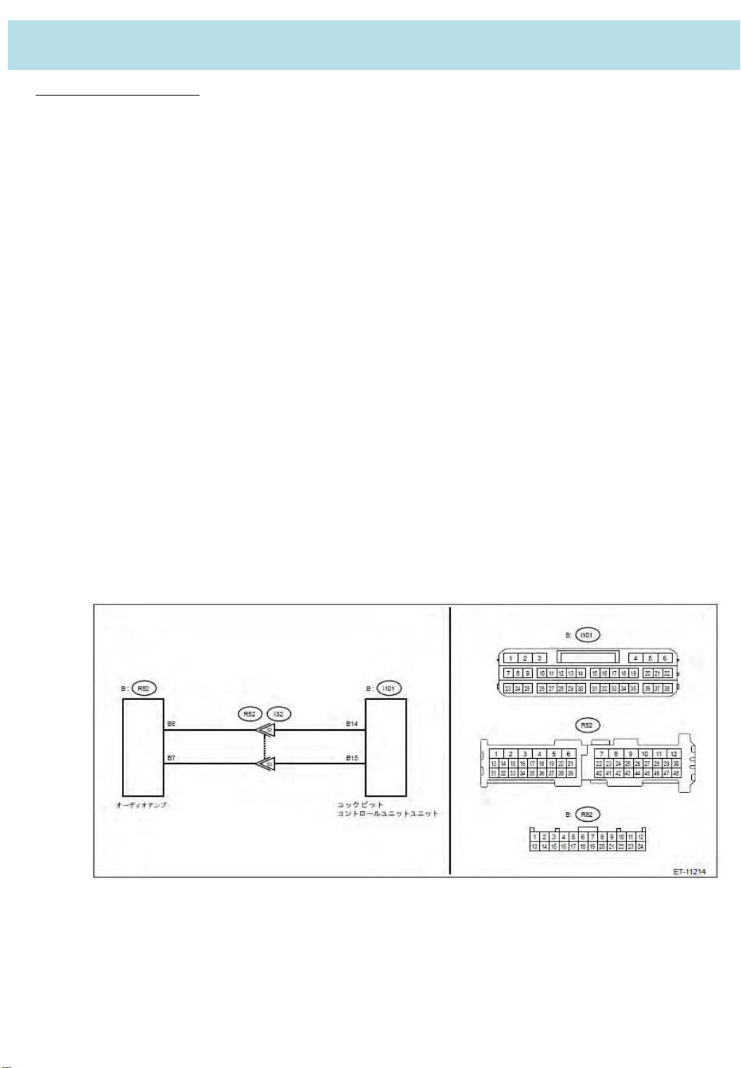
7. The example that utilized DTC
䠖
78
7.1. Inspection Mode
Activating inspection mode enables DTC diagnosis.
After repairing a DTC, activate the required inspection mode, and check to see if the function is
correctly restored and if a DTC is stored.
1. Use the SUBARU select monitor to clear the "Cockpit Control" memory.
2. Use the SUBARU select monitor to read the "Cockpit Control" DTC, and check that no DTC are
displayed.
If a DTC is displayed, then a malfunction continues to exist. Perform trouble
diagnosis of the displayed DTC. After repairing the DTC, repeat the process from step 1 above.
3. Turn the ignition switch ON and wait 1 minute or more.
4. Use the SUBARU select monitor to read the "Cockpit Control" DTC, and check that no DTC are
displayed.
< Example >
DTC B2244 [AMPLIFIER COMMUNICATION ]
DTC detection condition:
㻌 With the ignition switch turned to ACC ON, the DTC is detected if no communication
comes from the audio amplifier and a connection cannot be confirmed.
Trouble symptom䠖
㻌 The speaker does not output any audio.
Page 79

1. Check the fuse
79
Check the fuse for CCU and CDM module( 20A ).
Check result is OK?
Yes
No
Go to 2.
Replace fuse.
If the replacement fuse is blown immediately, repair any shorts to ground in the wiring
harness between the battery and audio amplifier.
2. Check wiring harness (open circuit)
1. Turn the ignition switch OFF.
2. Disconnect the cockpit control unit connector.
3. Disconnect the audio amplifier connector.
4. Using a tester, measure the resistance between the cockpit control unit connector and the audio amplifier
connector.
㻌 Connector & terminal
㻌㻌(i101) No. 14 — (R82) No. 8䠖
㻌㻌(i101) No. 15 — (R82) No. 7䠖
Is the resistance less than 1 ɏ?
Yes
No
Go to 3.
Repair the open circuit in the wiring harness between the cockpit control unit connector
and the audio amplifier.
3. Check wiring harness 㻌 ( ground short )
Using a tester, measure the resistance between the cockpit control unit connector and body ground.
Connector & terminal
(i101) No. 14 — Chassis ground䠖
(i101) No. 15 — Chassis ground䠖
Is the resistance more than 1 ɏ?
Yes
No
4. CHECK HARNESS (SHORT CIRCUIT TO POWER SUPPLY).
1. Turn the ignition switch ON.
2. Using a tester, measure the voltage between the cockpit control unit connector and body ground.
(With each connector disconnected )
㻌 Connector & terminal
㻌㻌㻌(i101) No. 14 (+) — Chassis ground䠖
㻌㻌㻌(i101) No. 15 (+) — Chassis ground䠖
㻌㻌㻌Is the resistance less than 1 V?
Yes
No
Go to 4.
Repair the ground short in the wiring harness between the cockpit control unit connector and
the audio amplifier.
Go to 5.
Repair the power supply short circuit in the wiring harness between the cockpit control
unit connector and the audio amplifier.
5. CHECK DTC.
Use the SUBARU select monitor to read the "Cockpit Control" DTC.
Is DTC B2244 displayed?
No
Replace the audio amplifier. Yes
A DTC is displayed, but the circuit has for now returned to a normal status.
Perform diagnosis again after reproducing the defect.
Page 80
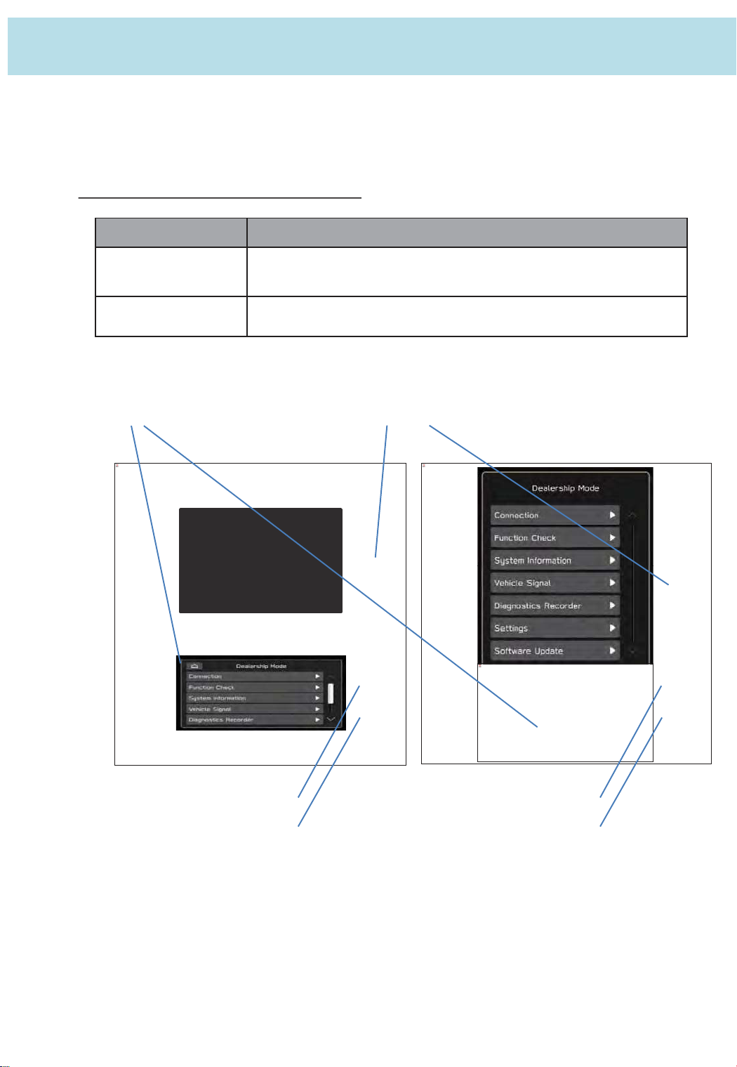
8. Dealership Mode
80
The infotainment system has a self-check function (Dealership mode) which can be performed
on the screen. The function enables functions including checking the system operation status,
displaying the system status, and checking system information.
8.1. Enter and Exit Dealership Mode
Dealership Mode Mode transition process
Enter
Push the TUNE knob six times while simultaneously pressing
down on both sides of the passenger side A/C up/down switch.
Exit Press the home button on the screen.
HOME button
TUNE knob
A/C UP Switch
A/C DOWN Switch
A/C UP Switch
A/C DOWN Switch
Page 81
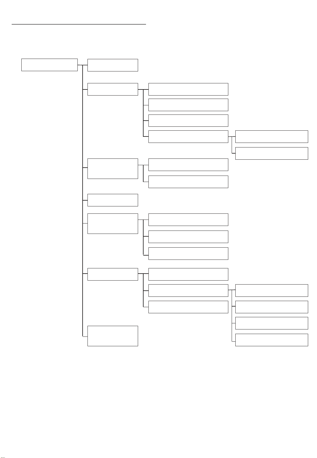
8.2. Dealership Mode Screen Transition
81
Dealership mode is accessed by by selecting the operation item from the seven items on the
menu, and can perform troubleshooting, function and information checks, and data collection.
Dealership Mode
Connection
Function Check Panel and Steering Switch
Touch Switch
Microphone
Navigation System Sensor
System
Information
Vehicle Signal
Diagnostics
Recorder
Product Information
Version Information
Begin Recording
Export Data to USB
System Sensors Check
GNSS Information *2
Clear Recorded Data
Settings
Software
Update
*1: High grade models only.
*2: Excluding China and for high grade models only.
*3: For rear cameras connected by NTSC only limited to vehicles where installed.
Memory Initialization
Camera Setting
DMS Demo Mode *1
Restore Default
Static Guide Line*3
Caution
Camera Setting*3
Page 82
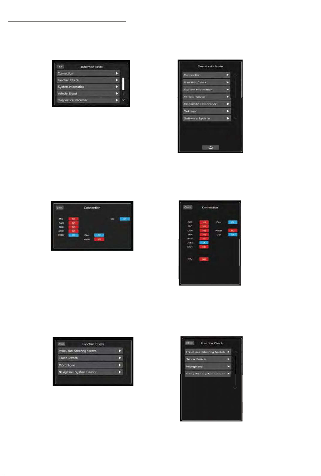
8.3. Menu of the Dealership mode
82
(1) Dealership Mode
Displays each item of the self check function.
(Lower Screen)
(2) Connection
- Displays the connection status of the devices connected to the Cockpit Control Unit (CCU).
- AUX, USB1, and USB2 displays the device connection status to each port.
(Lower Screen)
(3) Function Check
- Displays the operation status of connected devices such as switches, knobs, and touch panels.
- Models with navigation systems installed display the correction learning level and antenna
reception information
(Lower Screen)
Page 83
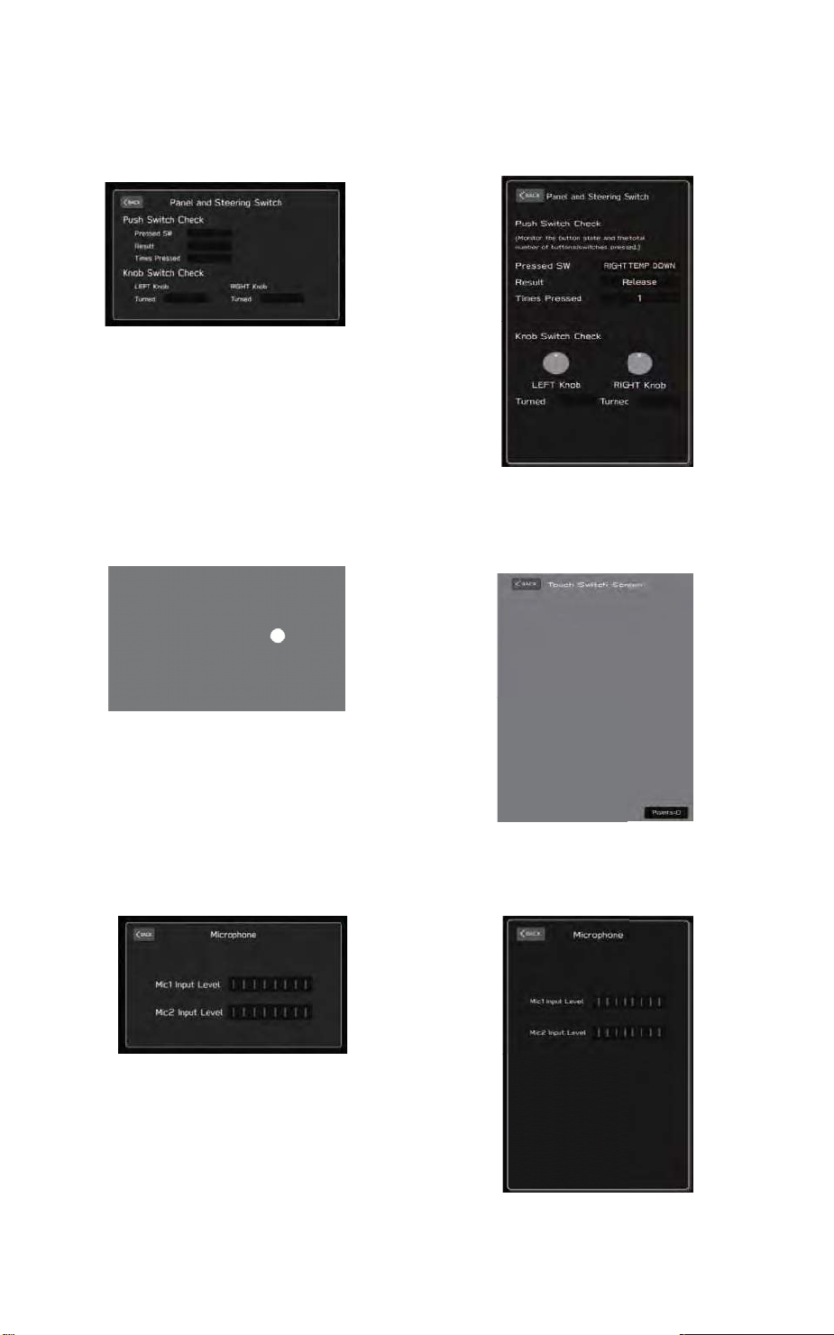
(3)-1.Panel and Steering Switch
83
Displays the switches and knobs of the Center Information Display (CID), and the
steering switch operation status.
(Lower Screen)
(3)-2.Touch Switch
Displays the touch panel operation status of the Center Information Display (CID).
(Upper/Lower Screen)
(3)-3.Microphone
Displays the operation status of the map lamp mounted microphone.
(Lower Screen)
Page 84
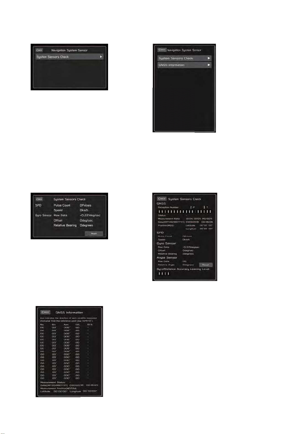
(3)-4.Navigation System Sensor
84
Performs functions such as resetting the operation status display and values of each
navigation module sensor.
(Lower Screen)
(3)-4-1.System Sensors Check
- Displays the operation status of each navigation module sensor.
- Resets each sensor value.
- Displays the navigation antenna reception status and operation status of each navigation
module sensor, and the distance correction learning level. (11.6-inch Display Navigation)
(Lower Screen)
(3)-4-2.GNSS Information ( 11.6-inch Display Navigation )
Displays navigation antenna reception information.
* The GPS inspection must be inspected under
GPS receivable condition.
Page 85
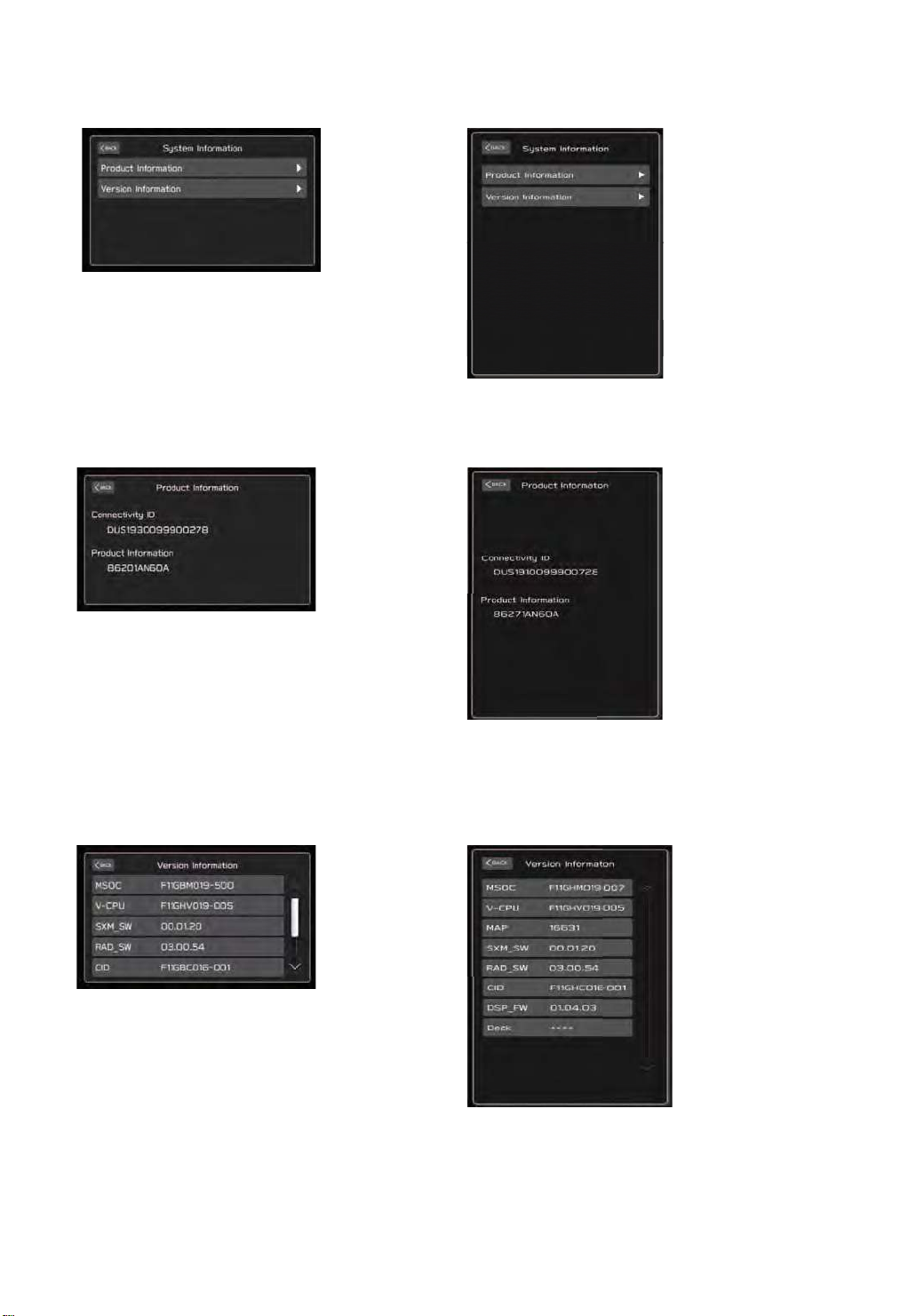
(4) System Information
85
Displays the information of the connected devices.
(Lower Screen)
(4)-1.Product Information
Displays the product information of the STARLINK connection ID and Cockpit Control Unit (CCU).
(Lower Screen)
(4)-2.Version Information
Displays the module version built into or connected to the Cockpit Control Unit (CCU).
(Lower Screen)
Page 86
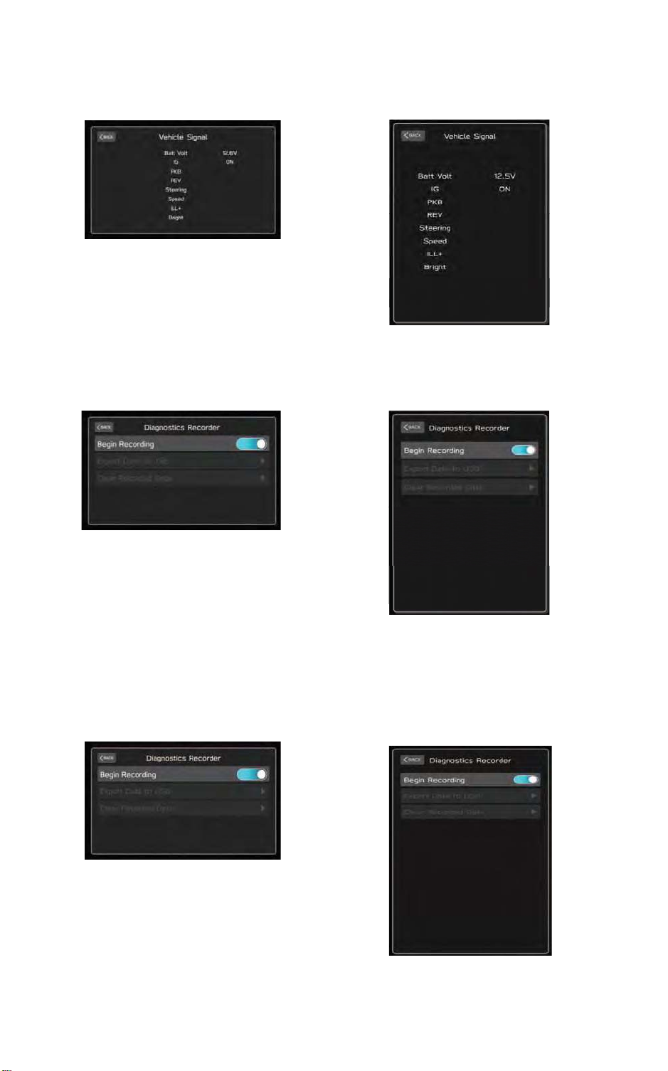
(5) Vehicle Signal
86
Displays the vehicle signal status.
(Lower Screen)
(6) Diagnostics Recorder
Operated to output or delete diagnosis recorder settings and data.
(Lower Screen)
(6)-1.Begin Recording
Turns on and off of the diagnosis recorder function.
Please stop the recording before you output diagnosis recorder data to a USB.
(Lower Screen)
Page 87
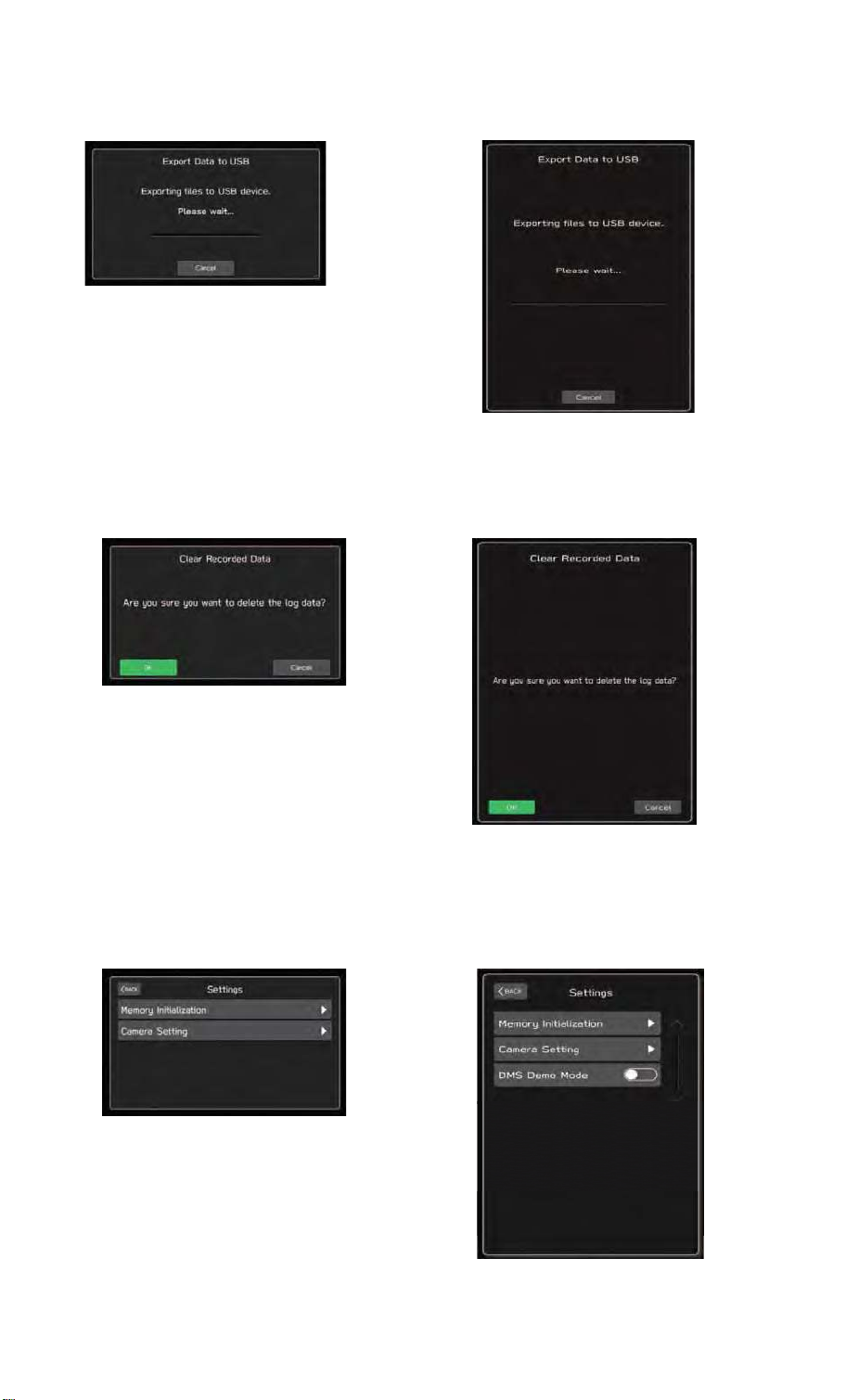
(6)-2.Export Data to USB
87
Can be used to output diagnosis recorder data to a USB.
(Lower Screen)
(6)-3.Clear Recorded Data
Deletes of diagnosis recorder data.
(7) Settings
This screen can Initialize the internal memory and Set the function of Camera.
And also the DMS Demo mode can be provided.
(Lower Screen)
(Lower Screen)
Page 88
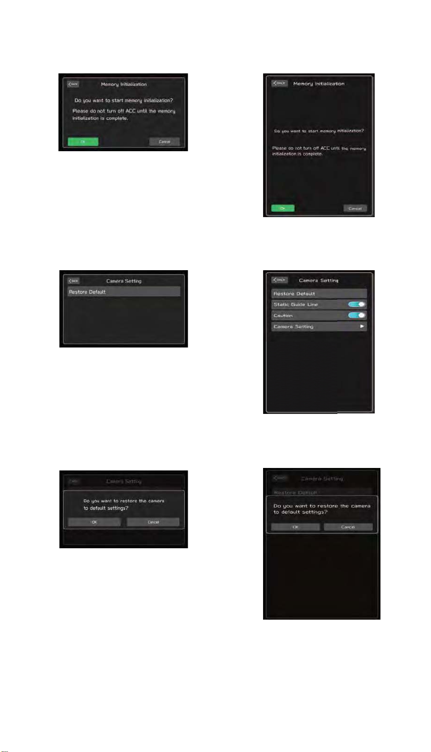
(7)-1.Memory Initialization
88
Initializes of the internal memory.
(Lower Screen)
(7)-2.Camera Setting
Adjusts and sets the camera.
(Lower Screen)
(7)-2-1.Restore Default
Restores the static guide line and caution settings to the default values.
(Lower Screen)
Page 89
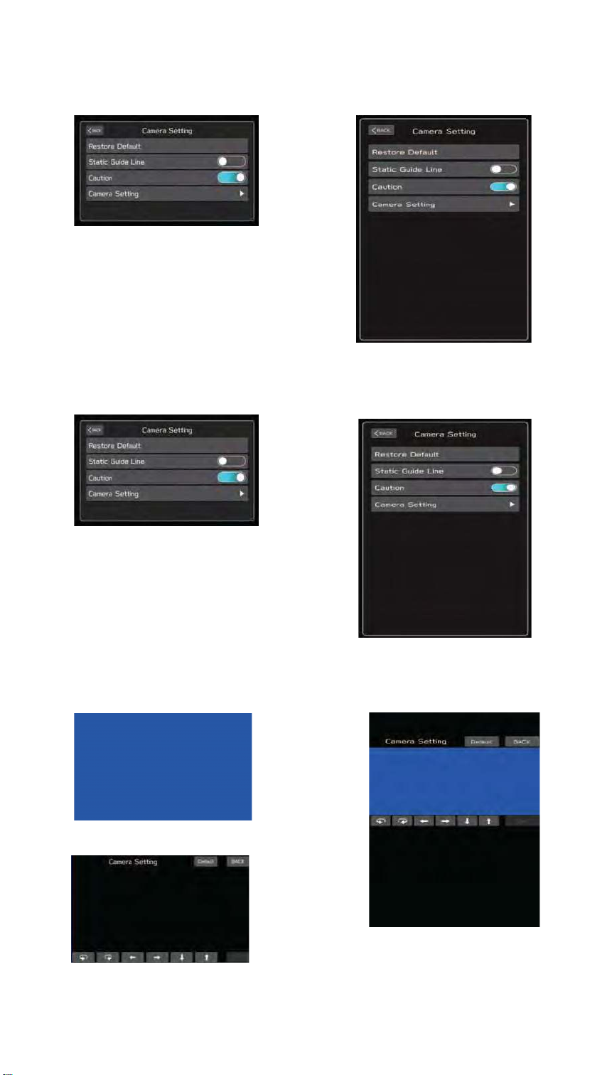
(7)-2-2.Static Guide Line
89
Turns on and off the rear camera screen guideline display.
(Lower Screen)
(7)-2-3. Caution
Turns on and off the rear camera screen and heads-up display.
(Lower Screen)
(7)-2-4.Camera Setting
Adjusts the rear camera screen guideline display position.
(Upper Screen)
(Lower Screen)
Page 90
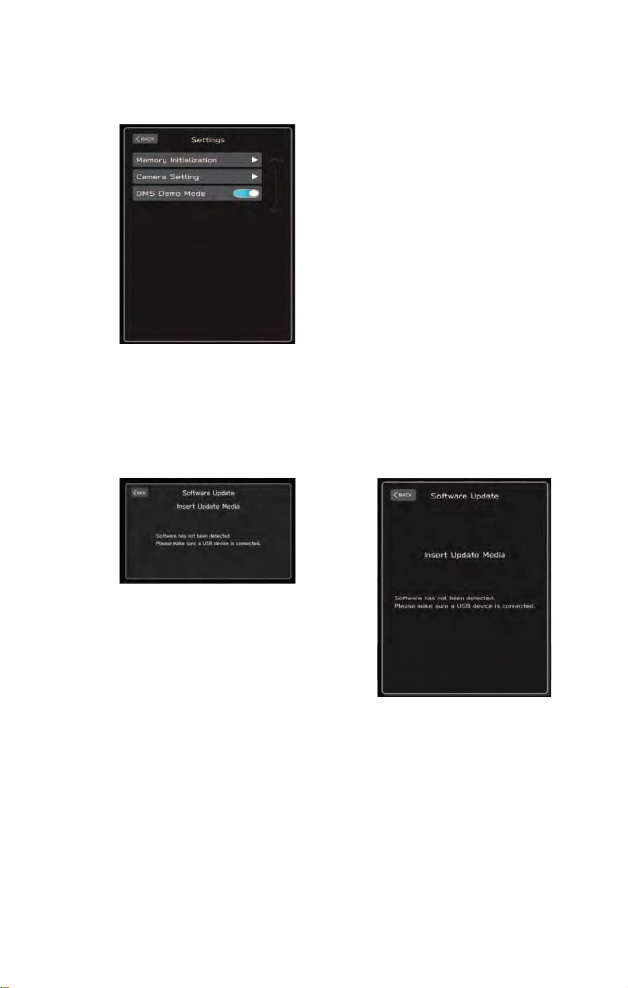
(7)-2-5. DMS Demo Mode (for Vehicles Equipped with Driver Monitoring Systems)
90
Turns on and off of the DMS Demo Mode.
(8) Software Update
Updates of information system data using USB memory.
(Lower Screen)
Page 91

91
Page 92
9䠊Troubleshooting Chart According to Malfunction Symptom
92
No.
㻌
1
The map cannot be updated from a USB flash drive
㻌
2㻌 USB flash drive connection is not recognized
3㻌 CarPlay does not start up
4㻌 NFC does not operate
5㻌 Cannot connect to Android Auto with a USB cable
6㻌 StarLink does not start up (USB connection)
7㻌 StarLink does not start up (BT connection)
8㻌 The CID screen shows as a black screen
9㻌 Meter: Screen does not display
10㻌 Meter: The screen flickers or repeatedly appears and disappears
11㻌 Meter: The screen is freezing
12㻌 Meter: The meter display is flickering
13㻌 Meter: The meter display does not disappear even when the engine is off
14㻌 FOTA cannot be performed
15㻌 MOTA cannot be performed
16㻌 The tell tail does not turn on (for a seatbelt reminder)
17㻌 The tell tail does not turn on (for the airbag)
18㻌 The audio does not play (from a USB flash drive)
19 CID: Screen does not display( Rear View Camera )
Malfunction Symptoms
㻌
㻌
㻌
㻌
㻌
㻌
㻌
㻌
㻌
㻌
㻌
㻌
㻌
㻌
㻌
㻌
㻌
㻌
Page 93

9.1 The map cannot be updated from a USB drive (CCU detects USB.)
93
(1) Probable Cause
ͻ USB data, CCU software
(2) Operation of MAP update by USB
Step1 : Push “Settings” icon.
Step2 : Push “Navigation” tab.
Step3 : Push “Map update” list item.
Step4 : Insert the USB device.
Step5 : Push “USB” icon.
Step6 : Insert activation code.
Step7 : MAP update starts.
(3) Problem
After inserting the USB device (step4) , 2 types of problem may occur.
Case (A) : CCU detects USB device, however, not move to step5.
The following message appears.
“Map data has not been detected, please ensure the USB device is properly inserted.”. Go to
step (4).
㻌
Case (B) : CCU does not detect USB device, therefore, not move to step5
No message appears.
Go to troubleshooting 8.2.
(4) Diagnosis
Explain how to fix “Case (A)”.
1. Check the CCU software version
Step1 : Push “Settings” icon.
Step2 : Push “General” tab.
Step3 : Push “System information” list item.
Step4 : Note “software version”. This version is CCU software version, need to confirm the latest.
2. Check the MAP data in the USB device
The MAP data may broken. Download the MAP data from the SUBARU WEB site and save to USB
device, again.
3. Check the installed CCU software
When the CID screen does not move from step5 to step6 , the installed CCU software may broken.
Perform the Factory Reset.
Step1 : Push “Settings” icon.
Step2 : Push “General” tab.
Step3 : Push “Factory Data Reset” list item.
Step4 : Push “Yes”.
Page 94
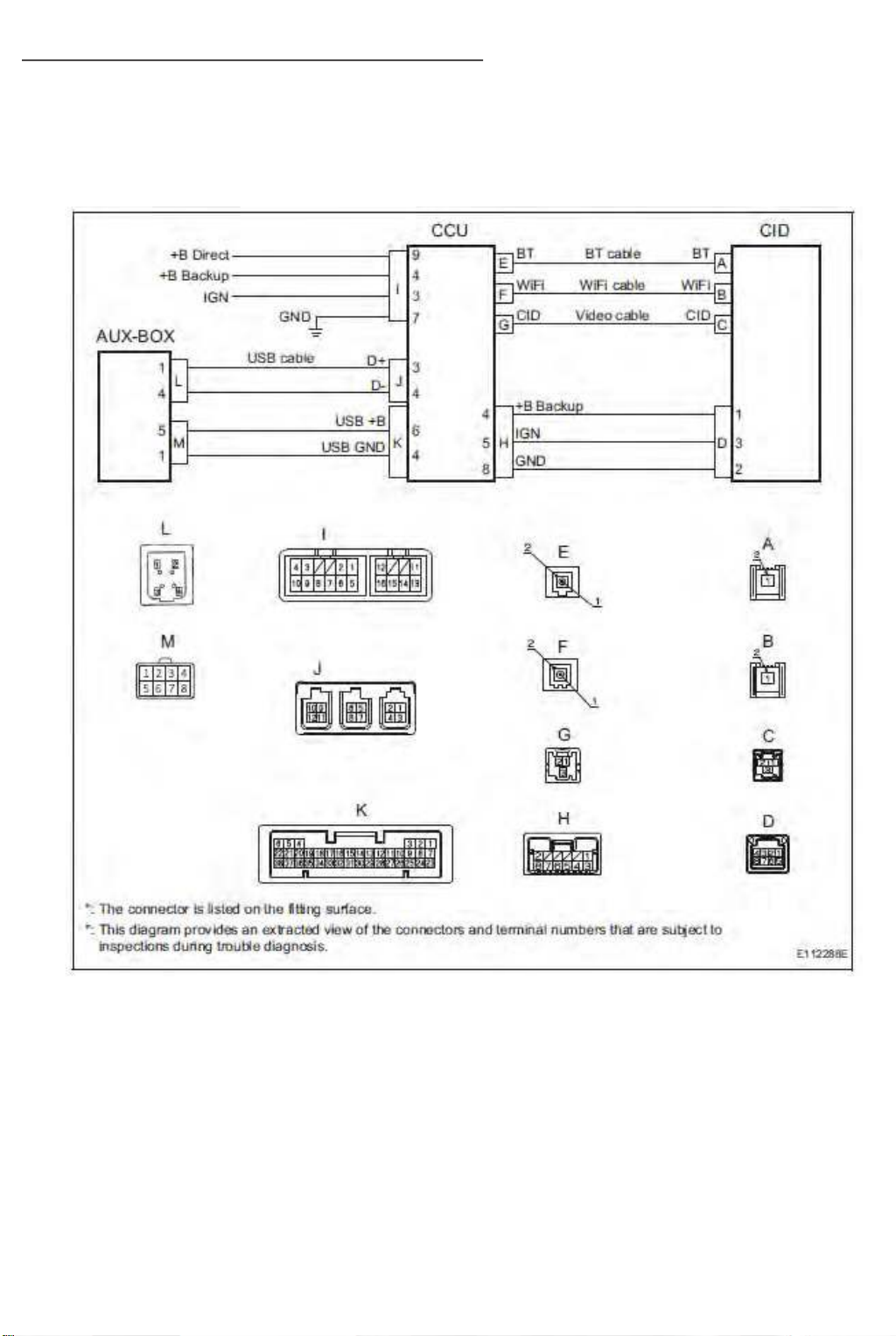
9.2 USB flash drive connection is not recognized
94
(1) Probable Cause
ͻ CCU abnormality or AUX-BOX abnormality
(2) Wiring Diagram/Connector Diagram
Page 95
(3)Diagnostic Procedure
95
1. Check of power supply and wiring harness
ͻ Check that the AUX-BOX connector and CCU connector fitting has been correctly connected
Connectors & Terminals
AUX-BOX Connector: ( L )
CCU Connector: ( J )
[ ADVICE ]
ͻ Disconnect the connector and insert until a clicking sound is heard
ͻ Confirm that the USB flash drive is recognized
No Proceed to the next step
Yes Could possibly be caused by faulty fitting of the connector. No current problems
ͻ Disconnect the connector (M) at AUX-BOX and check the voltage between the below terminals
Connectors & Terminals
Pin 5 (USB +B) of AUX-BOX Connector(M)
12V Replace the AUX-BOX
0V Proceed to the next step
ͻ Disconnect the connector (K) at CCU side and check the voltage between the below terminals.
Connectors & Terminals
Pin 6 (USB +B) of CCU Connector(K)
12V Replace the cable between USB and CCU
0V Proceed to the next step
ͻ Measure the connector (I) at CCU side and check the voltage between the below terminals.
Connectors & Terminals
Pin 9 (+B Direct) and/or Pin 4 (+B Backup) of CCU Connector(I)
12V Replace the CCU
0V Repair the cable between Battery and CCU.
Page 96
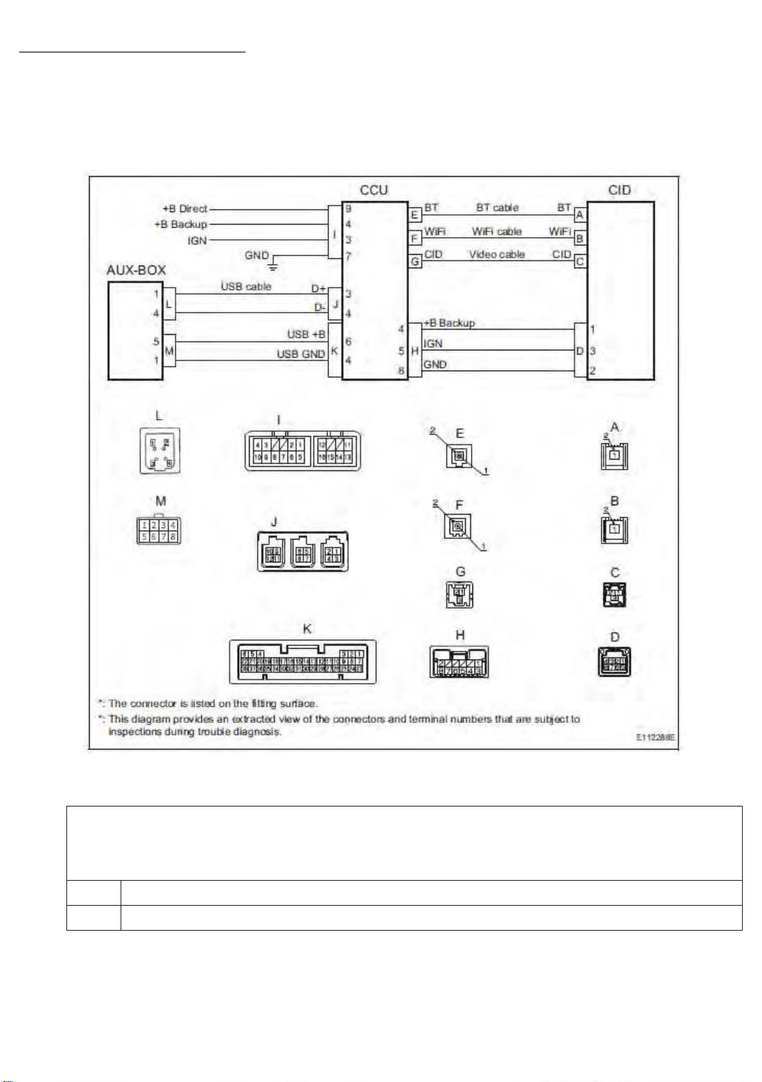
9.3 CarPlay does not start up
96
(1) Probable Cause
ͻ CCU abnormality, AUX-BOX abnormality, and mobile phone device specification mismatch
(2) Wiring Diagram/Connector Diagram
(3)Diagnostic Procedure
1. Check the DTC
ͻ Confirm whether the following DTC have been detected
㻌 B2256: Data Communication Module communication disconnection
No Proceed to step 2
Yes If these DTC are detected, proceed to the countermeasure for each DTC
Page 97
2. Check of device compatibility
97
ͻ Confirm the device version. Is the device an iPhone 5 or a higher version?
iPhone 5 or higher version Proceed to next steps
Others Not supported.
ͻ Confirm the iOS version.
10.2 or a higher version Proceed to next steps
Others Not supported.
ͻ Confirm the Application of “Siri”.
Enable Proceed to next steps
Not enable Set to Enable.
3. Check of the USB cable
CarPlay requires㻌 Data Com/Charging USB cable. It does not work with Wifi and/or Bluetooth.
ͻ Confirm the cable is Data Com/Charging type and is charging the phone.
Yes Proceed to next steps.
No Replace the cable.
4. Check of Carplay setup
ͻ Confirm other Carplay or AndroidAuto is working at CID.
Yes Remove the other device.
No Proceed to next steps.
ͻ Confirm Carplay setup of customer’s iPhone. Operate the following procedures.
Step1 : Push “Settings” icon.
Step2 : Push “Apple CarPlay” icon.
Step3 : Select “Device List” menu.
Step4 : Confirm 2 points.
- Your device are on the list ?
- Your device on the list has a check ?
5. Replace AUX-BOX
6. Replace CCU
Page 98
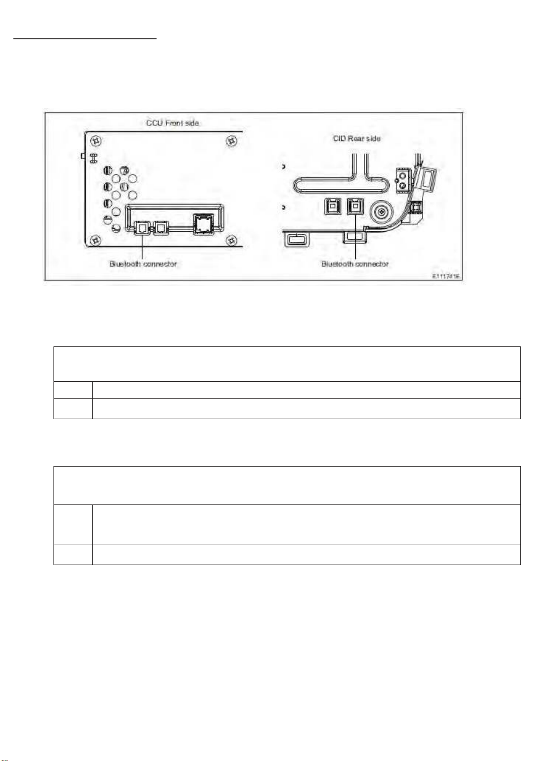
9.4 NFC does not operate
98
(1) Probable Cause
ͻ CCU abnormality or CID abnormality
(2) Wiring Diagram/Connector Diagram
(3)Diagnostic Procedure
1. Check the DTC
ͻ Confirm whether the following DTC have been detected
B2249: Bluetooth Module
No Proceed to step 2
Yes If these DTC are detected, proceed to the countermeasure for each DTC
2. Check the connection
ͻ Confirm whether the Bluetooth cable connector connecting the CCU and CID is correctly
connected or damaged
No ͻ Insert and remove the Bluetooth cable and check again.
ͻ If there is any damage, replace the Bluetooth cable and check again.
Yes Proceed to step 3
Page 99
3. Check of mobile phone device side
99
ͻ Is the mobile phone device power turned ON?
Check the connected mobile phone device. Is the power on?
No Turn on the power of the mobile phone device and check again.
Yes Proceed to the next step
ͻ Is the mobile phone device locked?
There is no security lock on the connected mobile phone device screen (the home screen is
displayed)
No Proceed to the next step
Yes Transition both the CCU and device to the home screen and check again
ͻ Is the mobile phone device set so that NFC can be used?
Check the connected mobile phone device. The NFC setting is switched on.
No Switch the device side NFC function setting power on, and then check again.
Yes Proceed to the next step
ͻ Is the mobile phone device compatible with Bluetooth? Is the mobile phone device set so that
Bluetooth can be used?
Check the connected mobile phone device. The Bluetooth setting is switched on.
㻌㻌No Set the Bluetooth connection, and check again.
Yes Proceed to step 4
4. Confirmation of details of malfunction occurrence
ͻ Can a standard Bluetooth connection be established instead of NFC?
: Select CCU Settings, Phone, Connect Phone, and and then Add to establish a device connection.
Does the device connect?
No Proceed to Procedure B
Yes Proceed to Procedure A
Procedure A
ͻ Does the video play normally, and does touch operation operate normally?
: Press the "HOME" switch, and check the screen display. Does the home screen display
without any resolution failure?
No 㻌 Video cable abnormality
㻌㻌Yes 㻌 CID abnormality (NFC chip abnormality)
Procedure B
ͻ Can a connection be established with another device?
: Establish an NFC connection on another device from the device used up until now. Can a
connection be established on another device?
No CCU abnormality
Yes Device abnormality
Page 100
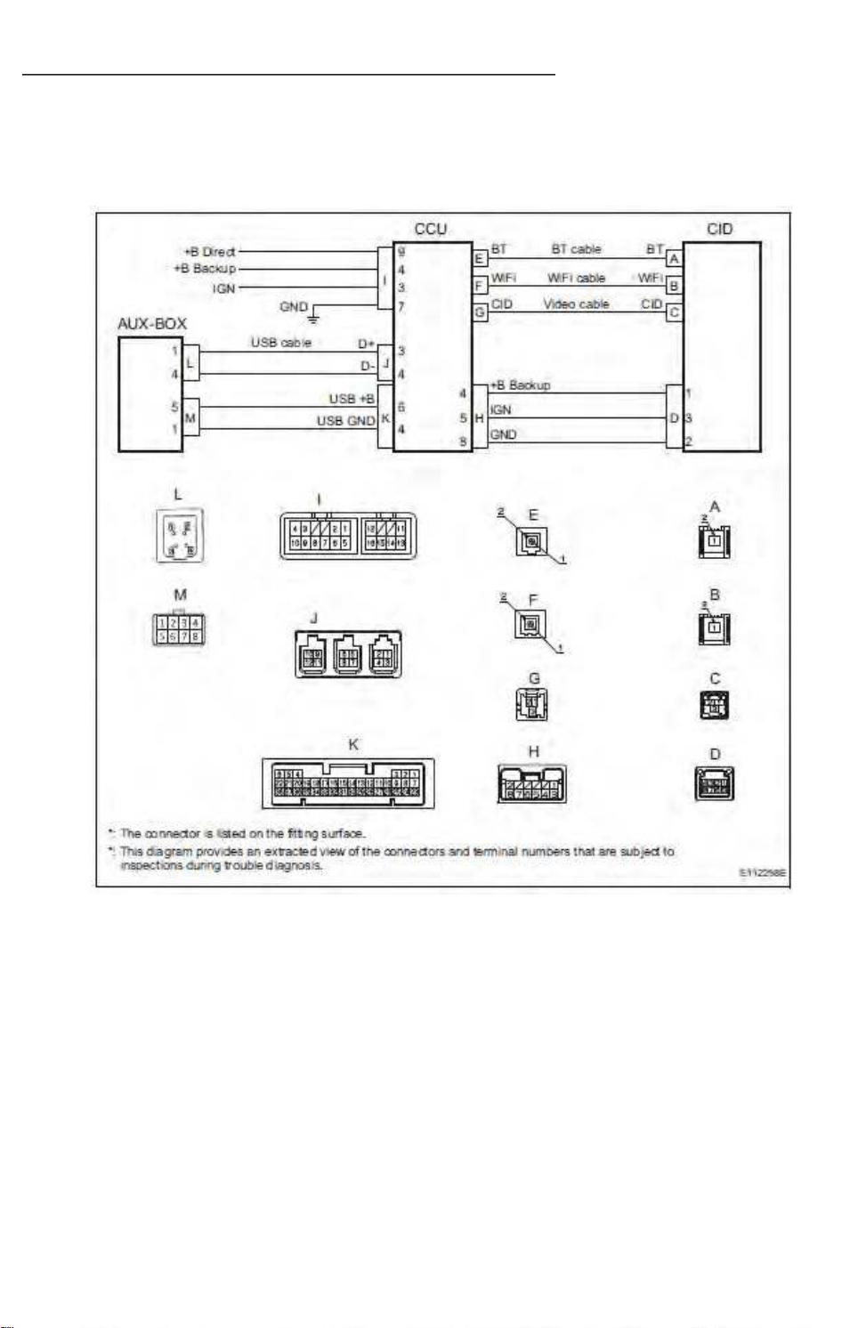
9.5 Cannot connect to Android Auto with a USB cable
100
(1) Probable Cause
ͻ CCU abnormality or AUX-BOX abnormality
(2) Wiring Diagram/Connector Diagram
 Loading...