

Page 1
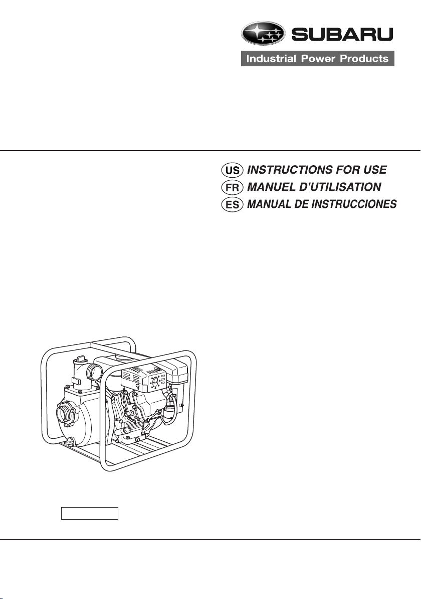
PKX series
201/301/401
201ST/301ST
201H
201T/301T/401T
210/310 220/320 220ST/320ST
9ZZ9990124
北米
SUBARU Pump
Page 2
1 2
5
1
4
3
PKX201,301,401, 201H,
201ST, 301ST, 220ST, 320ST,
210, 310, 220, 320
6
7
3
1
1
2
1
18
17
16
15
14
13
19
21 22
2
4
3
2
1112
23
PKX201T, 301T, 401T
5
6
2
9
2
3
4
5
Single
grade
Multi
grade
Ambient
temperature
2
3
5W
10W
20W
#20
#30
10W-30
10W-40
-20 -10 0 10 20 30
-4 14 32 50 68 86
#40
3
40 C
104 F
1
10
8
20
24
7
8
4
1
20
19
18
17
16
21
23 24
10 9
1415
1
1211
13
6
7
5
22
25
26
Page 3
PKX201,301,401, 201H,
6
5
1
6
201ST, 301ST, 220ST, 320ST,
210, 310, 220, 320
1
7 28
54 6
1
4
1
2
3
2
PKX201T, 301T, 401T
7 28
3
54 6
2
1
3
7
4
1
0.6 - 0.7 mm
Page 4
2
6
2
1
3
3
4
4
5
7
8
1
5
2
1
1
Page 5

NOTICE
FEDERAL EMISSION COMPONENT DEFECT WARRANTY and CALIFORNIA
EMISSION CONTROL WARRANTY are applicable to only those engines/
generators complied with EPA (Environmental Protection Agency) and CARB
(California Air Resources Board) emission regulations in the U.S.A.
NOTICE
To the engines/generators exported to and used in the countries other than the
U.S.A., warranty service shall be performed by the distributor in each country in
accordance with the standard SUBARU engine/generator warranty policy as applicable.
Page 6

Page 7
FOREWORD
Thank you very much for purchasing a SUBARU PUMP.
This manual covers operation and maintenance of SUBARU PUMP.
All information in this publication is based on the latest product information available at the
time of approval for printing. Please read this manual carefully before operating.
Please take a moment to familiarize yourself with the proper operation and maintenance
procedures in order to maximize the safe and efficient use of this product.
Keep this owner’s manual at hand, so that you can refer to it at any time.
Due to constant efforts to improve our products, certain procedures and specifications are
subjected to change without notice.
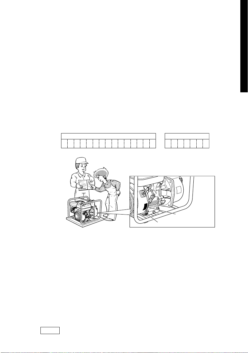
When ordering spare parts, always give us the MODEL, PRODUCTION NUMBER and SERIAL
NUMBER of your pump.
Please fill in the following blanks after checking the production number on your pump.
(Location of label is different depending on the pump specification.)
ENGLISH
PROD No.
SER No. (Stamping
SER No.
PROD No. / SER No.
(
)
Label
)
CONTENTS
Page
1. SAFETY PRECAUTIONS................................................................................... 2
2. COMPONENTS.................................................................................................. 5
3. PRE-OPERATION FOR STARTING .................................................................. 6
4. OPERATING YOUR PUMP ................................................................................ 7
5. MAINTENANCE ................................................................................................. 7
6. PREPARATIONS FOR STORAGE..................................................................... 10
7. OIL SENSOR INSTRUCTIONS
............................................................................
8. SPARK ARRESTER (OPTIONAL)...................................................................... 10
9. EASY TROUBLESHOOTING............................................................................. 11
10. SPECIFICATIONS .............................................................................................. 12
NOTE Please refer to the illustrations on the back page of the front
cover or back cover for Fig.
1 1
ii
1 to
i indicated in the sentence.
1 1
ii
10
FRANÇAISE
ESPAÑOL
1
Page 8
1. SAFETY PRECAUTIONS
Please make sure you review each precaution carefully.
Pay special attention to statement preceded by the following words.
“WARNING” indicates a strong possibility of severe personal injury or loss of life if
instructions are not followed.
“CAUTION” indicates a possibility of personal injury or equipment damage if instructions
are not followed.
ENGLISH
WARNING
CAUTION
WARNING
■
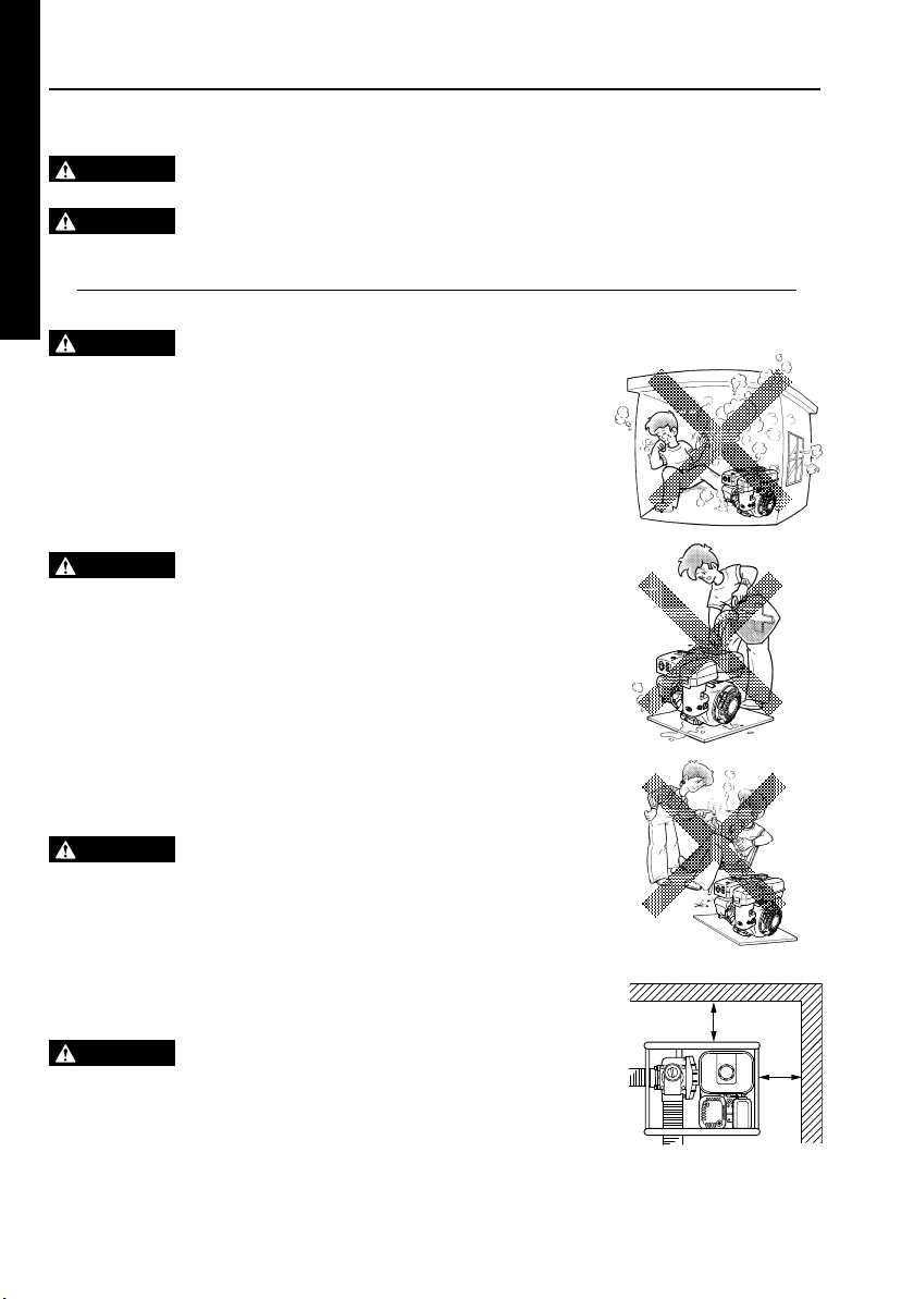
Never inhale exhaust gasses.
: EXHAUST PRECAUTIONS
They contain carbon monoxide, a colorless, odorless and extremely dangerous gas
which can cause unconsciousness or death.
■
Never operate the pump indoors or in a poorly ventilated area, such as tunnel, cave,
etc.
■
Exercise extreme care when operating the pump near people or animals.
■
Keep the exhaust pipe free of foreign objects.
FRANÇAISE
WARNING
■
Gasoline is extremely flammable and its vapors can explode if ignited.
■
Do not refuel indoors or in a poorly ventilated area.
■
Be sure to stop the pump prior to refueling.
■
Do not remove fuel tank cap nor fill fuel tank while engine is hot or running.
: REFUELING PRECAUTIONS
Allow engine to cool at least 2 minutes before refueling.
■
Do not overfill the fuel tank.
■
If fuel is spilt, wipe it away carefully and wait until the fuel has dried before starting the
engine.
■
After refueling, make sure that the fuel cap is secured to prevent spillage.
ESPAÑOL
WARNING
■
Do not operate the pump while smoking or near an open flame.
■
Do not use around dry brush, twigs, cloth rags, or other flammable materials.
■
Keep cooling air intake (recoil starter area) and muffler side of the engine at least
: FIRE PREVENTION
1 meter (3 feet) away from buildings, obstructions and other burnable objects.
■
Keep the pump away from flammables and other hazardous materials (trash, rags,
lubricants, explosives).
WARNING
■
Be careful of hot parts.
: OTHER SAFETY PRECAUTIONS
The muffler and other engine parts become very hot while the pump is running or just
after it has stopped. Operate the pump in a safe area and keep children away from
the running pump.
■
Do not use diaphram pump for the mixture of water and oil.
■
Do not touch the spark plug and ignition cable when starting and operating the engine.
1m
1m
2
Page 9
■
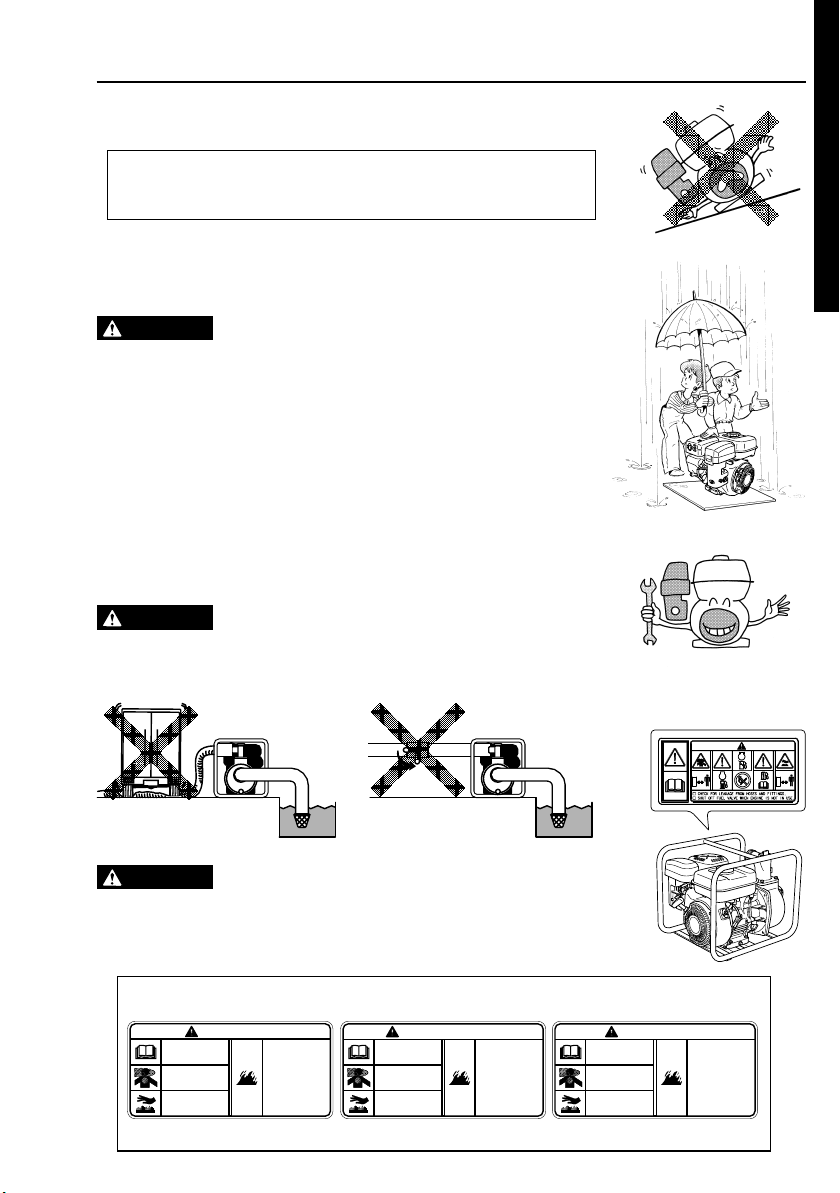
Operate the pump on a stable, level surface.
If the engine is tilted, fuel spillage may result.
NOTE
Operating the pump at a steep incline may cause seizure due to improper lubrication
even with a maximum oil level.
■
Do not transport the pump with fuel in tank or with fuel strainer valve open.
■
Keep the unit dry (do not operate it in rainy conditions).
ENGLISH
CAUTION
■
Carefully check fuel hoses and joints for looseness and fuel leakage. Leaked fuel
: PRE-OPERATION CHECKS
creates a potentially dangerous situation.
■
Check bolts and nuts for looseness. A loose bolt or nut may cause serious engine
trouble.
■
Check the engine oil and refill if necessary.
■
Check the fuel level and refill if necessary. Take care not to overfill the tank.
■
Keep cylinder fins and recoil starter free of dirt, grass and other debris.
■
Wear snug fitting working clothes when operating the engine.
Loose aprons, towels, belt, etc., may be caught in the engine or drive train, causing a
dangerous situation.
CAUTION
■
Do not allow the delivery hose to be trampled over by a vehicle’s wheel, or do not
: BEWARE OF WATER-HAMMERING
close the delivery valve abruptly otherwise a water-hammer occurs which may result
heavy damage to the pump.
Trampling over the delivery hose Abrupt closing of delivery valve
:
CAUTION
■
Warning labels are affixed to our engines with regard to particularly serious dangers.
PRECAUTIONS ON THE HANDLING OF THE
WARNING LABEL
When using the engines, please use them safely after carefully reading the instruction
manual and understanding the dangers.
FRANÇAISE
STOP
STOP
ESPAÑOL
Warning Label Exclusively for the United States and Canada
ᵵᵟᵰᵬᵧᵬᵥ
ᵰᶃᵿᶂᴾᵧᵬᵱᵲᵰᵳᵡᵲᵧᵭᵬᵱ
ᵤᵭᵰᴾᵳᵱᵣᴾᶀᶃᶄᶍᶐᶃᴾᶓᶑᶃᵌ
ᵲᶆᶃᴾᶃᶌᶅᶇᶌᶃᴾᶃᶋᶇᶒᶑᴾᶒᶍᶖᶇᶁᴾᶅᵿᶑ
ᶁᵿᶌᴾᶉᶇᶊᶊᴾᶗᶍᶓᴾᶇᶌᴾᶋᶇᶌᶓᶒᶃᶑᵌᴾᴾᵢᶍ
ᶌᶍᶒᴾᶐᶓᶌᴾᶇᶌᴾᵿᶌᴾᶃᶌᶁᶊᶍᶑᶃᶂᴾᵿᶐᶃᵿᵌ
ᵦᶍᶒᴾᶑᶓᶐᶄᵿᶁᶃᴾᶁᵿᶌᴾᶀᶓᶐᶌᴾᶗᶍᶓᵌ
ᵱᶒᵿᶗᴾᵿᶕᵿᶗᴾᶇᶄᴾᶃᶌᶅᶇᶌᶃᴾᶆᵿᶑ
ᶀᶃᶃᶌᴾᶐᶓᶌᶌᶇᶌᶅᵌ
ᵥᵿᶑᶍᶊᶇᶌᶃᴾᶇᶑᴾᶃᶖᶒᶐᶃᶋᶃᶊᶗ
ᶄᶊᵿᶋᶋᵿᶀᶊᶃᴾᵿᶌᶂᴾᶇᶒᶑᴾᶔᵿᶎᶍᶐᶑ
ᶁᵿᶌᴾᶃᶖᶎᶊᶍᶂᶃᵌ
Ὁᵱᶒᶍᶎᴾᶒᶆᶃᴾᶃᶌᶅᶇᶌᶃᴾᶀᶃᶄᶍᶐᶃ
ᴾᶐᶃᶄᶓᶃᶊᶇᶌᶅᵌ
ᵡᶆᶃᶁᶉᴾᶄᶍᶐᴾᶊᶃᵿᶉᵿᶅᶃẅᶄᶐᶍᶋ
Ὁ
ᴾᶆᶍᶑᶃᶑᴾᵿᶌᶂᴾᶄᶇᶒᶒᶇᶌᶅᶑᵌ
ᶄᶓᶃᶊᴾᶔᵿᶊᶔᶃᴾᶕᶆᶃᶌ
Ὁᵱᶆᶓᶒᴾᶍᶄᶄᴾ
ᴾᶒᶆᶃᴾᶃᶌᶅᶇᶌᶃᴾᶇᶑᴾᶌᶍᶒᴾᶇᶌᴾᶓᶑᶃᵌ
For use in the United States or Canada, please affix the label suited to the region from among the enclosed warning labels.
AVERTISSEMENT
Lire les INSTRUCTIONS
POUR L'USAGE avant d’
utiliser le moteur.
Le moteur émet un gaz toxique
qui peut tuer l’opérateur en
quelques minutes.
Ne pas utiliser le moteur dans
un emplacement fermé.
La surface chaude peut vous
brûler.
S’éloigner du moteur s’il est en
marche.
L'essence est extrêmement
inflammable et ses vapeurs
peuvent exploser.
• Arrêter le moteur avant de
faire le plein en combustible.
• Vérifier toute présence de
fuite à partir des tuyaux et
garnitures.
• Bloquer la soupape de
carburant quand le moteur
n’est pas utilisé.
ADVERTENCIA
Leer las INSTRUCCIONES
PARA EL USO antes de utilizar
el motor.
El motor emite un gas tóxico
que puede matar el operador
en algunos minutos.
No utilizar el motor en un sitio
cerrado.
La superficie caliente puede
quemarles.
Alejarse del motor si es en
marcha.
La gasolina es extremadamente
inflamable y sus vapores
pueden estallar.
• Detener el motor antes de
hacer el lleno en combustible
• Comprobar si hay presencia
de fuga a partir los tubos y
guarniciones
• Bloquear la válvula de
combustible cuando no se
utiliza el motor.
3
Page 10
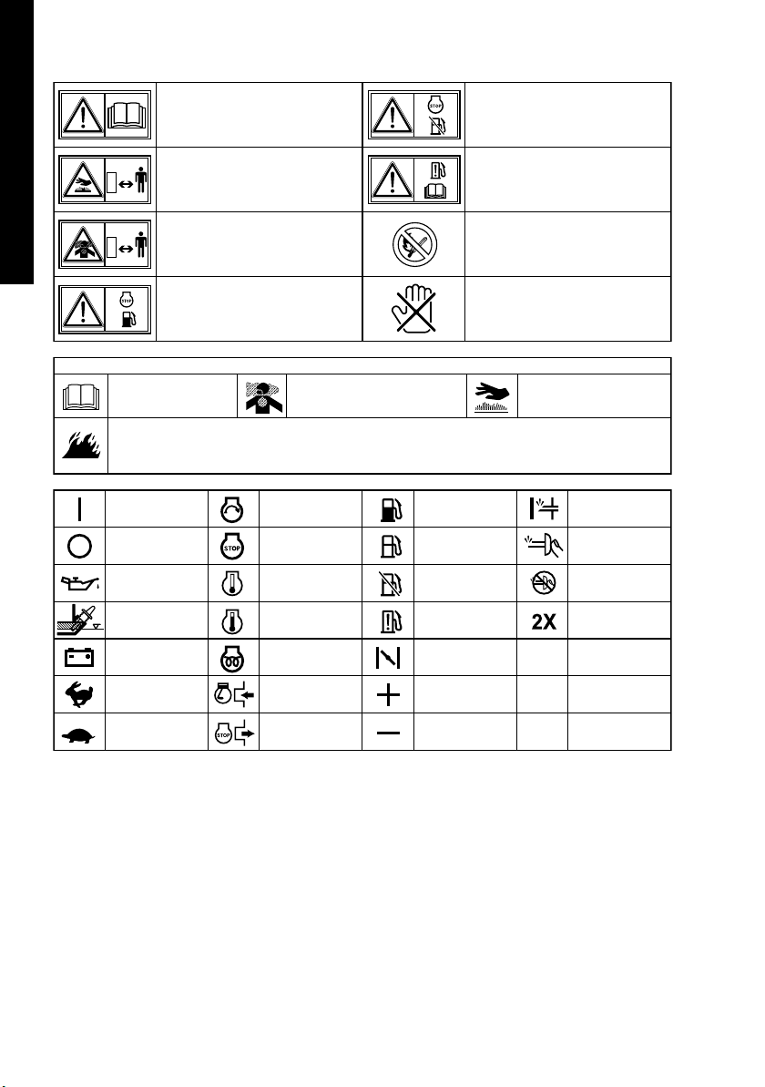
SYMBOLS
ENGLISH
USA and CANADA only
FRANÇAISE
ESPAÑOL
Read manual.
Stay clear of the hot surface.
Exhaust gas is poisonous.
Do not operate in an unventilated
room or enclosed area.
Stop the engine before refueling.
Read INSTRUCTIONS
FOR USE before use.
Gasoline is extremely flammable and its vapors can explode.
• Stop the engine before refueling.
• Check for leakage from hoses and fittings.
• Shut off fuel valve when the engine is not in use.
On (Run)
Off (Stop)
Engine oil
Add oil
Battery
Fast
Slow
The engine emits toxic gas
can kill you in minutes.
Do not run in an enclosed area.
Engine start
(Electric start)
Engine stop
Cold engine
Warm engine
Electrical preheat
(Low tem-perature start aid)
Run position
Stop position
D
Shutt off fuel valve
when the engine is not in use.
Check for leakage
from hose and fittings.
Fire, open flame and smoking
prohibited.
HOT, avoid touching the hot area.
Hot surface can burn you.
Stay away if engine has
been running.
Fuel (gasoline)
Fuel (diesel)
Fuel shut-off
Fuel system
failure / malfunction
Choke
Plus ;
positive polarity
Minus ;
negative polarity
Primer
Push primer
Do not push primer
Two times
4
Page 11

2. COMPONENTS
(See Fig.
11
1)
11
NOTE Please refer to the illustrations on the back page of the front
cover or back cover for Fig.
1 1
ii
1 to
i indicated in the sentence.
1 1
ii
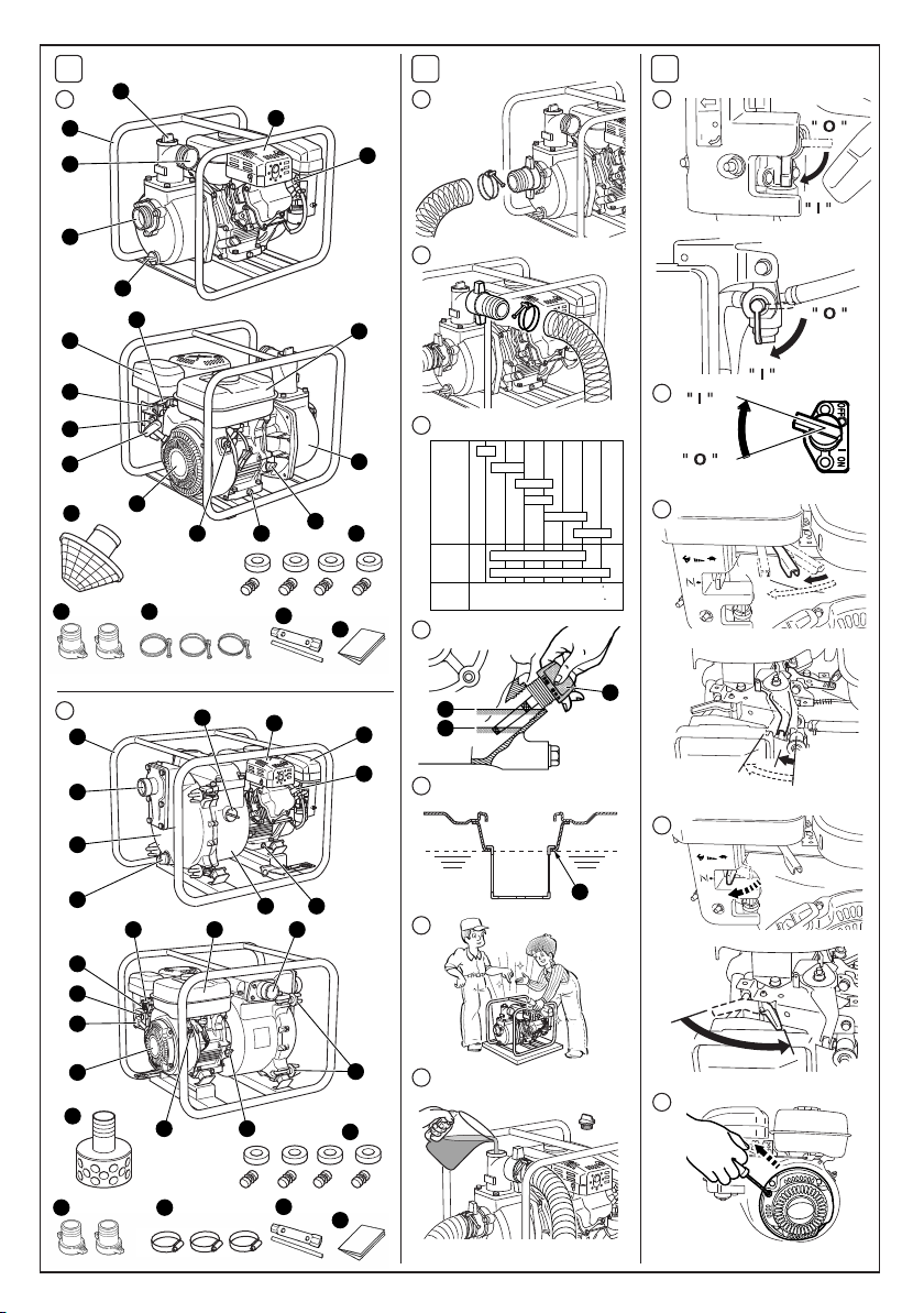
CENTRIFUGAL PUMP (PKX201, 301, 401, 201H, 210, 310, 220, 320)
SEMI TRASH PUMP (PKX201ST, 301ST, 220ST, 320ST)
11
(See Fig.
q Plug (drain)
w Suction
e Delivery
r Frame
t Plug (priming)
y Muffler
u Spark plug
i Oil filler (with oil guage)
o Fuel tank
*1 Except PKX220, 320, 220ST, 320ST
1
11
qq
q)
-
qq
!0 Casing cover
!1 Drain plug (at two places)
!2 Stop Switch
!3 Recoil starter
!4 Recoil Starter handle
!5 Fuel valve
!6 Chocke lever
!7 Air cleaner
!8 Speed control lever
!9 Strainer
@0 Cushion rubber
@1 Hose coupling *1
@2 Hose band
@3 Tools
@4 Instruction for use
(This publication)
TRASH PUMP (PKX201T, 301T, 401T)
11
(See Fig.
q Plug (drain)
w Casing
e Suction
r Frame
t Plug (priming)
y Muffler
u Air cleaner
i Spark plug
o Drain plug (at two places)
!0 Casing cover
1
11
ww
w)
-
ww
!1 Fuel tank
!2 Delivery
!3 Knob
!4 Oil filler (with oil guage)
!5 Stop switch
!6 Recoil Starter
!7 Recoil Starter handle
!8 Fuel valve
!9 Chocke lever
@0 Speed control lever
@1 Strainer
@2 Cushion rubber
@3 Hose coupling
@4 Hose band
@5 Tools
@6 Instruction for use
(This publication)
ENGLISH
FRANÇAISE
ESPAÑOL
5
Page 12
3.
PRE-OPERATION FOR STARTING
(See Fig.
22
2
22
)
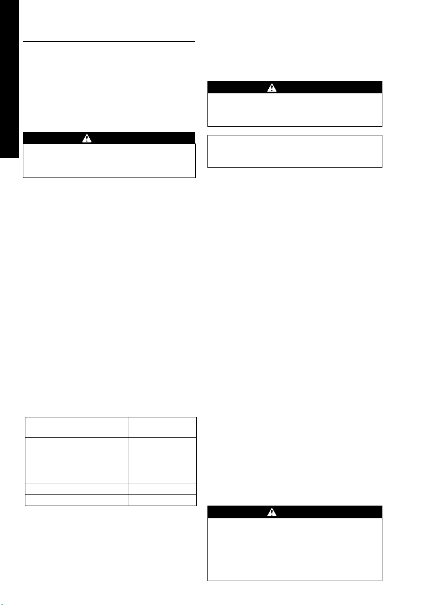
1. CONNECT SUCTION HOSE
qq
22
q)
(See Fig.
Use a reinforced-wall or wire braided hose to prevent suction
collapse.
ENGLISH
Since the pump self-priming time is directly proportional to
hose length, a short hose is recommended.
2
22
-
qq
CAUTION
Always use a strainer with the suction hose. Gravel
or debris sucked into the pump will cause serious
damage to the impeller and the pump casting.
2. CONNECT DELIVERY HOSE
ww
22
w)
(See Fig.
When using a fabric hose, always use a hose band to prevent
the hose from disconnecting under high pressure.
FRANÇAISE
3. CHECK ENGINE OIL (See Fig.
Before checking or refilling engine oil, be sure the engine is
located on stable, level surface and stopped.
■
Do not screw the oil gauge into the oil filler neck to check
oil level. If the oil level is low, refill to the upper level with
the following recommended oil.
■
Use 4-stroke automotive detergent oil of API service class
SE or higher grade (SG, SH or SJ is recommended).
■
Select the viscosity based on the air temperature at the
time of operation as shown in the table. (See Fig.2
Explanation of Fig.
ESPAÑOL
q Oil Gauge
w Upper Level
e Lower Level
PKX201, PKX301, PKX201H,
PKX201ST, PKX301ST,
PKX201T, PKX210, PKX310
PKX220, PKX320,
PKX220ST, PKX320ST
PKX401, PKX301T
2
22
Model
-
ww
rr
22
r)
2
-
rr
22
rr
22
r
-
2
rr
22
Oil capacity
Liter (U.S. gal)
0.6 (0.16)
1.1 (0.29)
PKX401T 1.2 (0.32)
6
4. CHECK FUEL (See Fig. 2-t)
WARNING
Do not refuel while smoking, near an open flame
or other such potential fire hazards. Otherwise
fire accident may occur.
NOTE
THIS ENGINE IS CERTIFIED TO OPERATE ON
AUTOMOTIVE UNLEADED GASOLINE.
■
Stop the engine and open the cap.
■
Use unleaded automotive gasoline only.
• Unleaded regular/premium or reformulated gasoline
containing no more than 10% Ethanol (E10), or 15%
MTBE may also be used.
• Never use gasoline containing ethanol exceeding
10%, or MTBE exceeding 15% because engine or
fuel system damage could result.
• Never use stale or contaminated gasoline.
• Use of these non-recommended fuels may result in
reduced performance and/or denial of warranty.
Fuel Tank Capacity
Refer to “10. SPECIFICATIONS” Page 12 or 13 for fuel tank
capacity
■
Close the fuel valve before filling the fuel tank.
-
q
-
y)
-
e)
Explanation of Fig.3
q Maximum Fuel level
■
Do not fill above the top of the fuel filter screen (marked q),
or the fuel may overflow when it heats up later and expands.
■
When filling the fuel tank, always use the fuel filter screen.
■
Reattach the fuel cap by turning clockwise until reaching
the physical stop (about one quarter turn). Do not attempt
to turn past the physical stop or the fuel cap may be
damaged.
■
Wipe off any spilled fuel before starting the engine.
(See Fig.2
5. CHECK PRIMING WATER
22
(See Fig.
It is recommended that the water chamber of pump casing
should be primed with full of water before operating.
2
22
uu
-
u)
uu
WARNING
Never attempt to operate the pump without priming
water or the pump will overheat. Extended dry
operation will destroy the mechanical seal.
If the unit has been operated dry, stop the engine
immediately and allow the pump to cool before
adding priming water.
Page 13

4. OPERATING YOUR PUMP
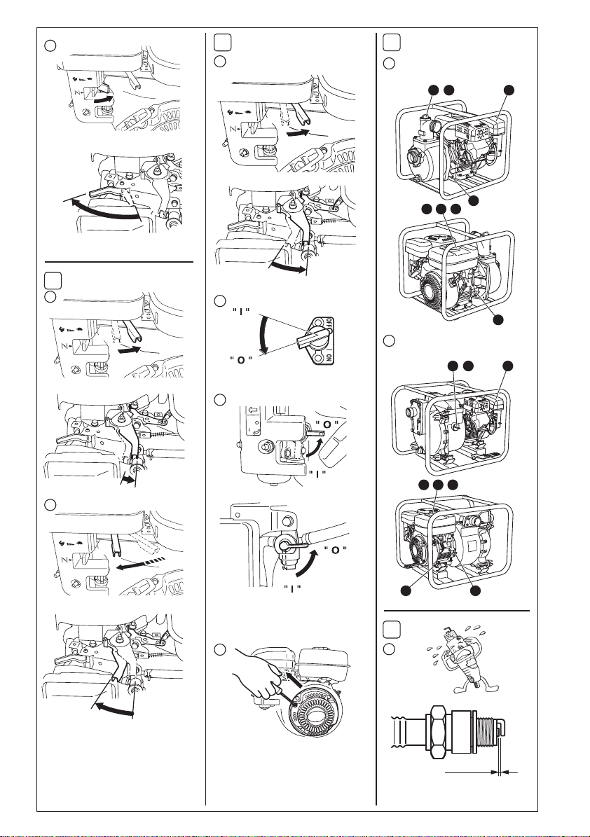
1. STARTING (See Fig.
(1) Open the fuel valve. (See Fig.3-q)
(2) Turn the STOP SWITCH to the position “
(See Fig.3
(3) Set the speed control lever 1/3 of the way towards the
high speed position. (See Fig.3-e)
(4) Close the choke lever. (See Fig.3
■
If the engine is cold or the ambient temperature is low,
close the choke lever fully.
■
If the engine is warm or the ambient temperature is high,
open the choke lever half-way, or keep it fully open.
(5) Pull the starter handle slowly until resistance is felt. This
is the “compression” point. Return the handle to its
original position and pull swiftly. Do not pull out the rope
all the way. After starting the engine, allow the starter
handle to return to its original position while still holding
the handle. (See Fig.3
(6) After starting the engine, gradually open choke by turning
the choke lever and finally keep it fully opened. Do not
fully open the choke lever immediately when the engine
is cold or the ambient temperature is low, because the
engine may stop. (See Fig.3
-
w)
2. RUNNING (See Fig.
(1) After the engine starts, set the speed control lever at the
low speed position (L) and warm it up without load for a
few minutes.
(See Fig.4
(2) Gradually move the speed control lever toward the high
speed position (H) and set it at the required engine speed.
(See Fig.4
■
Whenever high speed operation is not required, slow the
engine down (idle) by moving the speed control lever to
save fuel and extend engine life.
-
q)
-
w)
33
3)
33
” (ON).
I
-
r)
-
t)
-
y)
44
4)
44
3. STOPPING (See Fig.
(1) Set the speed control lever at the low speed position and
allow the engine to run at low speed for 1 or 2 minutes
before stopping.
(See Fig.5
(2) Turn the STOP SWITCH counterclockwise to the position
“
(3) Close the fuel valve. (See Fig.5
(4) Pull the starter handle slowly and return the handle to its
original po sition when resistance is felt. This operation is
necessary to prevent outside moist air from intruding
into the combustion chamber. (See Fig.5
※※
※ STOPPING ENGINE WITH THE FUEL VALVE
※※
Close the fuel valve and wait for a while until the engine stops.
Avoid to let the fuel remain in the carburetor over long periods,
or the passages of the carburetor may become clogged with
impurities, and malfunctions may result.
-
q)
◯◯
◯ ” (OFF). (See Fig.5-w)
◯◯
55
5)
55
-
e)
-
r)
5. MAINTENANCE
(See Fig.
MAINTENANCE, REPLACEMENT, OR REPAIR OF THE
EMISSION CONTROL DEVICES AND SYSTEMS MAY BE
PERFORMED BY ANY NONROAD ENGINE REPAIR
ESTABLISHMENT OR INDIVIDUAL.
1. DAILY INSPECTION
Before running the engine, check the following service items.
q Loose or broken bolts and nuts
w Clean air cleaner element
e Enough clean engine oil
r Leakage of gasoline and engine oil
t Enough gasoline
y Safe surroundings
u Check the priming water
i Excessive vibration, noise
66
6
66
)
ENGLISH
FRANÇAISE
ESPAÑOL
7
Page 14

2. PERIODIC INSPECTION
Periodic maintenance is vital to the safe and efficient operation
of your pump.
Check the table below for periodic maintenance intervals.
Replace rubber pipes for fuel passage every two
years. If fuel leakage is found, replace the pipe
immediately.
CAUTION
IT IS ALSO NECESSARY FOR THE USER OF THIS PUMP
TO CONDUCT THE MAINTENANCE AND ADJUSTMENTS
ON THE EMISSION-RELATED PARTS LISTED BELOW TO
KEEP THE EMISSION CONTROL SYSTEM EFFECTIVE.
ENGLISH
3. INSPECTING THE SPARK PLUG
qq
77
q)
(See Fig.
(1) Clean off carbon deposits on the spark plug electrode
7
77
-
qq
using a plug cleaner or wire brush.
The emission control system consists of the following parts :
(1) Carburetor and internal parts
(2) Cold start enrichment system, if applicable
(3) Intake manifold, if applicable
(4) Air cleaner elements
(5) Spark plug
(6) Magneto or electronic ignition system
(7) Spark advance/ retard system, if applicable
(8) Exhaust manifold, if applicable.
(9) Hoses, belts, connectors, and assembles
The maintenance schedule indicated in the following table is
FRANÇAISE
based on the normal engine operation.
Should the engine be operated in extremely dusty condition
or in heavier loading condition, the maintenance intervals must
be shortened depending on the contamination of oil, clogging
of filter elements, wear of parts, and so on.
(2) Check electrode gap. The gap should be 0.6 mm to 0.7
mm (0.02 inch. - 0.03 inch.). Adjust the gap, if necessary,
by carefully bending the side electrode.
Model Recommended Spark Plug
PKX201, PKX301, PKX401
PKX201H
PKX201ST, PKX301ST
PKX201T, PKX301T, PKX401T
PKX210, PKX310
PKX220, PKX320
PKX220ST, PKX320ST
4.
ENGINE OIL CHANGE (See Fig.
NGK BR-6HS
TORCH E6RC
Initial oil change : After 20 hours of operation
Thereafter : Every 100 hours of operation
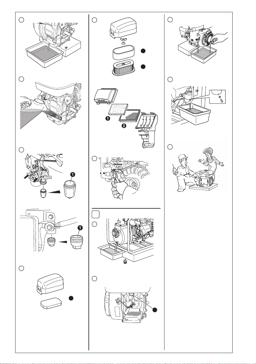
(1) When changing oil, stop the engine and loosen the drain
plug. Drain the used oil while the engine is warm. Warm
oil drains quickly and completely.
Periodic Maintenance Schedule table
Maintenance Items
Clean pump set and check bolt and nuts
Check for leakage from hoses and fitting ● (Daily)
Check and refill engine oil
ESPAÑOL
Change engine oil (*Note 1)
Clean spark plug
Clean air cleaner
Clean spark arrester (Optional part)
Replace air cleaner element
Clean fuel cup
Clean and adjust spark plug and electrodes
Replace spark plug
Remove carbon from cylinder head (*Note 2)
Check and adjust valve clearance (*Note 2)
Clean and adjust carburetor (*Note 2)
Replace fuel lines
Overhaul engine if necessary (*Note 2)
*Note 1: Initial oil change should be performed after first twenty (20) hours of operation. Thereafter change oil every hundred
(100) hours. Before changing oil, check for a suitable way to dispose of old oil. Do not pour it down
onto garden soil or into open streams. Your local zoning or environmental regulations will give you more detailed instructions
on proper disposal.
*Note 2: As to the procedures for these items, please refer to the SERVICE MANUAL or consult your nearest service dealer.
Every 8 hours
(Daily)
● (Daily)
●
(Refill daily up to upper level)
(Initial 20 hours)
●
Every 50 hours
(Weekly)
● (Every 100 hours)
● (Every 100 hours)
●
● (Every 100 hours)
Every 200 hours
(Monthly)
●
●
●
Every 500 hours Every 1000 hours
●
●
●
●
into sewage drains,
ww
ee
77
w,
e)
7
-
ww
ee
77
● (Every 2 years)
●
8
Page 15
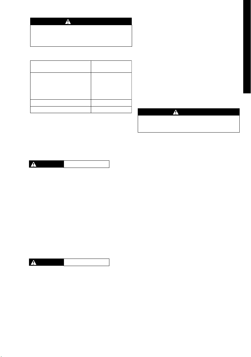
CAUTION
To prevent injury, pay attention to the hot oil.
Make sure the fuel cap is tightly secured to avoid
spillage.
(2) Re-install the drain plug before refilling oil.
Model
PKX201, PKX301, PKX201H,
PKX201ST, PKX301ST,
PKX201T, PKX210, PKX310
PKX220, PKX320,
PKX220ST, PKX320ST
PKX401, PKX301T
PKX401T 1.2 (0.32)
(3) Refer to page 6 for the recommended oil.
■
Always use the best grade and clean oil. Contaminated
oil, poor quality oil and shortage of oil cause damage to
engine or shorten the engine life.
5. CLEANING FUEL CUP (See Fig.
WARNING
(1) Inspect fuel cup for water and dirt.
(See Fig.7
(2) To remove water and dirt, close the fuel valve and
remove the fuel cup.
(3) After removing dirt and water, wash the fuel cup with
kerosene or gasoline. Reinstall securely to prevent
leakage.
Flame Prohibited
-r-
q)
Oil capacity
Liter (U.S. gal)
0.6 (0.16)
1.1 (0.29)
rr
77
r)
7
-
rr
77
6. CLEANING AIR CLEANER
tt
yy
77
-
t,
(See Fig.
A dirty air cleaner element will cause starting difficulty, power
loss, engine malfunctions, and shorten engine life extremely.
Always keep the air cleaner element clean.
WARNING
(1) Urethane Foam Element Type
(See Fig.7
Remove the element and wash it in washing oil
(kerosene). Then saturate it in engine oil and squeeze
it firmly before installing. (See Fig.7
(2) Urethane Foam Dual Element Type
(See Fig.7
■
For EX13/16/17 urethane foam, remove it from the
paper element and wash it in washing oil (kerosene).
Then saturate it in engine oil and squeeze it firmly
before installing. (See Fig.7
y)
7
tt
yy
77
Flame Prohibited
-
t)
-
y)
-y-
w)
-t-
q)
■
For EX27/40 urethane foam, remove it from the paper
element and wash it thoroughly with detergent. Then
-y-
dry it before installing. (See Fig.7
■
For the paper element, clean by blowing on it with
compressed air from the inside or tapping on it gently
to remove dirt. Change the paper element when doing
this fails to remove the dirt.
(See Fig.7
Clean and replace air cleaner elements more often
when operating in dusty environments.
7.
FUEL HOSE REPLACEMENT (See Fig.
-y-
q)
w)
77
7
77
uu
u)
-
uu
WARNING
Take extreme caution when replacing fuel
hose ; gasoline is extremely flammable.
Replace the fuel hose every 1,000 hours or every 2 years.
If fuel leaks from fuel hose, replace the fuel hose immediately.
8.
CHECKING BOLTS, NUTS AND SCREWS
■
Retighten loose bolts and nuts.
■
Check for fuel and oil leaks.
■
Replace damaged parts with new ones.
9. CLEANING PUMP INSIDE
■
Turn the knob counterclockwise and open the casing
cover holder.
■
Pull the casing toward you, and then remove the casing
and the inner casing.
■
Clean the inside of pump casing and casing cover with
clean water.
10. HIGH ALTITUDE ENGINE OPERATION
■
Please have an authorized SUBARU Industrial Power
Products dealer modify this engine if it is to be run
continuously above 5000 feet (1500 meters). Failure to
do so, may result in poor engine performance, spark
plug fouling, hard starting, and increased emissions.
■
Carburetor modification by an authorized SUBARU
Industrial Power Products dealer will improve
performance and allow that this engine meets
(Environmental Protection Agency) and California ARB
Resources Board) emission standards throughout
life.
■
An engine converted for high altitudes can not be run at
5000 feet or lower. In doing so, the engine will overheat
and cause serious engine damage.
Please have an authorized SUBARU Industrial Power
Products dealer restore high altitude modified engines
to the original factory specification before operating
below 5000 feet.
EPA
(Air
its useful
ENGLISH
FRANÇAISE
ESPAÑOL
9
Page 16
6. PREPARATIONS FOR STORAGE
qq
88
1. WATER (See Fig.
Drain all water from the drain plug.
When retightening drain plug, be sure to
the drain plug and the thread of casing.
Otherwise, the thread may be damaged.
ENGLISH
2. DISCONNECT THE DELIVERY HOSE
Tilt the pump and drain all water from delivery hole. Severe
damage to pump may result if water freezes in the pumping
chamber.
3.
DISCHARGE FUEL (See Fig.
WARNING Flame Prohibited
If you do not use the engine more than 1 month, discharge
fuel to prevent gum in the fuel system and carburetor parts.
■
Remove the strainer cup, place the strainer over a
container and open the strainer valve to discharge fuel
from the fuel tank. (See Fig.8
FRANÇAISE
■
Remove the drain screw of the carburetor float chamber
and discharge fuel. (See Fig.8
4. ENGINE OIL (See Fig.
■
Change the engine oil with fresh oil.
■
Remove the spark plug, pour about 5 cc of engine oil
into the cylinder, slowly pull the starter handle of the
recoil starter 2 or 3 times, and reinstall the spark plug.
q)
8
-
qq
88
CAUTION
-
-
88
8
88
e)
-
r)
tt
t)
tt
88
8
88
-
e e
e
e e
clean
thru
8. SPARK ARRESTER (OPTIONAL)
1. SPARK ARRESTER
In a dry or wooded area, it is recommendable to use the
product with a spark arrester. Some areas require the use
of a spark arrester. Please check your local laws and
regulations before operating your product.
The spark arrester must be cleaned regularly to keep it
functioning as designed. A clogged spark arrester:
■
Prevents the flow of exhaust gas
■
Reduces engine output
■
rr
r)
rr
Increases fuel consumption
■
Makes starting difficult
CAUTION
If the engine has been running, the muffler
and the spark arrester will be very hot. Allow
the muffler to cool before cleaning the spark
arrester.
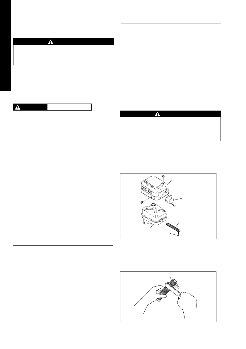
How to remove the spark arrester
1. Remove the flange bolts from the muffler cover and
remove the muffler cover.
2. Remove the special screw from the spark arrester and
remove the spark arrester from the muffler.
MUFFLER COVER
5. CLEAN AND STORE
■
Slowly pull the recoil starter handle until resistance is
felt and leave it in that position.
ESPAÑOL
■
Clean the pump thoroughly with an oiled cloth, put the
cover on, and store the pump indoors in a well ventilated,
low humidity area.
7. OIL SENSOR INSTRUCTIONS
(OPTIONAL)
1. FUNCTION OF OIL SENSOR
The engine will stop automatically when the oil level falls
below the safety limit. The engine cannot be started unless
the level is raised above the prescribed limit.
(See Fig.2
2. RESTARTING
(1) Fill the crankcase with oil up to the proper level.
(2) As for restarting and operating the engine, refer to
10
-
r)
section “4. OPERATING YOUR PUMP” on page 7.
■ Check the wire connector from the engine. It must be
connected securely to the wire from oil sensor.
■ When selecting the engine oil, refer to page 6 for the
recommended oil.
DEFLECTOR
SPARK
ARRESTER
SCREEN
MUFFLER
SCREW
Clean the spark arrester screen
Use a brush to remove carbon deposits from the spark
arrester screen. Be careful to avoid damaging the screen.
The spark arrester must be free of breaks and holes.
Replace the spark arrester if it is damaged.
SPARK ARRESTER SCREEN
Install the spark arrester, and muffler protector in the
reverse order of disassembly.
Page 17
9. EASY TROUBLESHOOTING
1. PUMP DOES NOT RUN .
■
Engine dose not start.
(See 9.-4 “4. WHEN ENGINE DOES NOT START
■
Sticking of impeller
(Disassemble and clean.)
2. PUMPING VOLUME IS SMALL.
■
Sucking air at suction side.
(Check piping at suction side.)
■
Drop off engine output
(Consult your nearest dealer.)
■
Breakage of mechanical seal.
(Consult your nearest dealer.)
■
High suction lift (Lower.)
■
Suction hose is too long or thin.
(Use a thick hose in minimum length.)
■
Leak of water from water passage.
(Stop leaking.)
■
Clogging of foreign substance in impeller.
(Disassemble and clean.)
■
Wear of impeller.
■
Looseness of suction chamber. (Retighten)
■
Strainer is clogged. (Clean.)
■
Engine speed is too low.
(Consult your nearest dealer.)
3. PUMP DOES NOT SELFPRIME.
■
Suction of air at suction side.
(Check piping at suction side.)
■
Insufficient priming water inside pump casing
(Prime fully.)
■
Imperfect tightening of drain plug.
(Tighten the plugs completely.)
■
Engine speed is too low.
(Consult your nearest dealer.)
■
Sucking air from mechanical seal.
(Consult your nearest dealer.)
4. WHEN ENGINE DOES NOT START :
Perform the following checks before you take the pump to
your SUBARU Industrial Power Products dealer. If you still
”)
have trouble after completing the checks, take the pump to
your nearest SUBARU Industrial Power Products dealer.
(1) Is there a strong spark across the electrode ?
■
Is the stop switch at position “ I ” (ON)?
■
Remove and inspect the spark plug.
If the electrode is fouled, clean or replace it with new
one.
■
Remove the spark plug and connect it to the plug cap.
Pull the starter handle while grounding spark plug against
engine body. Try with a new spark plug if the spark is
weak or there is no spark.
The ignition system is faulty if there is no spark with a
new spark plug.
WARNING
■
Wipe out spilled fuel carefully before testing.
Place spark plug as far away from spark plug
hole as possible.
■
Do not hold spark plug by hand while pulling
recoil starter.
NOTE
The engine with oil sensor will stop automatically when
the oil level falls below the prescribed limit.
Unless the oil level is raised above the prescribed limit,
the engine will stop immediately after starting.
(2) Is there enough compression?
Pull the starter handle slowly and check if resistance is
felt. If little force is required to pull the starter handle,
check if the spark plug is tightened firmly. If the spark
plug is loose, tighten it.
(3) Is the spark plug wet with gasoline?
■
Is the fuel valve opened?
■
Choke (close choke lever) and pull the starter handle five
or six times. Remove the plug and check if its electrode
is wet. If the electrode is wet, fuel is well supplied to your
engine.
■
When the electrode is dry, check where the fuel stops.
(Check the fuel intake of the carburetor.)
■
In case the engine does not start with well supplied fuel,
try using fresh fuel.
ENGLISH
FRANÇAISE
ESPAÑOL
11
Page 18
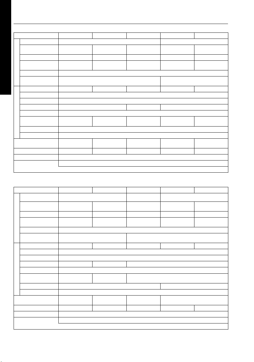
10. SPECIFICATIONS
MODEL
Suction x Delivery
Diameters mm(in.)
Total Head m(ft)
Maximum Delivery Volume
ENGLISH
PUMPENGINE
Liter(U.S.gal) / min
Suction Head m(ft)
Axle Seal Material
(Mechanical Seal)
Model
Type
Lublicant
Oil Capacity Liter (U.S.gal)
Fuel
Fuel Tank Capacity
Liter (U.S.gal)
Spark plug
Starting system
Dimensioms
(L x W x H) mm (in.)
FRANÇAISE
Net Weight kg (lb)
Standard accessories
Valve Clearance
(Intake and Exhaust)
MODEL
Suction x Delivery
Diameters mm(in.)
Total Head m(ft)
Maximum Delivery Volume
PUMPENGINE
Liter(U.S.gal) / min
ESPAÑOL
Suction Head m(ft)
Axle Seal Material
(Mechanical Seal)
Model
Type
Lublicant
Oil Capacity Liter (U.S.gal)
Fuel
Fuel Tank Capacity
Liter (U.S.gal)
Spark plug
Starting system
Dimensioms
(L x W x H) mm (in.)
Net Weight kg (lb)
Standard accessories
Valve Clearance
(Intake and Exhaust)
PKX201
50 x 50 (2 x 2) 80 x 80 (3 x 3) 100 x 100 (4 x 4) 50 x 50 (2 x 2) 80 x 80 (3 x 3)
30 (98) 31 (102) 27 (89) 30 (98) 28 (92)
600 (158) 970 (256) 1350 (356) 580 (153) 930 (246)
EX13 EX17 EX27
Automotive detergent oil (API / SE or higher grade, SG, SH or SJ is recommended, SEA / 10W-30 etc.)
2.3 (0.61) 3.2 (0.85) 5.6(1.48)
486x357x399
(18.43x14.06x15.71)
24 (52.91) 30 (66.14) 51 (112.44)
PKX201T PKX301T PKX201H
Self-priming, Trash pump Self-priming, Centrifugal pumpType
50 x 50 (2 x 2) 80 x 80 (3 x 3) 50 x 50 (2 x 2)
29 (95) 25 (82) 57 (187)
700 (185) 1190 (314) 480 (127)
EX17
Automotive detergent oil (API / SE or higher grade, SG, SH or SJ is recommended, SEA / 10W-30 etc.)
0.6 (0.16)
3.2 (0.85) 5.6(1.48)
620x462x481
(24.1x18.19x18.94)
48 (105.82) 58 (127.87)
• Specifications are subject to change without notice
PKX301 PKX401 PKX201ST
Self-priming, Centrifugal pumpType
8 (26)
Ceramic - carbon Silicon - carbide
Air - Cooled, 4 - cycle, OHC, Gasoline Engine
0.6 (0.16)
505x387x467
(19.88x15.24x18.39)
Engine tool kit (1set), Strainer (1pc.), Cussion rubber (1set), Hose band (3pcs.)
Note : Adjust the valve clearance while the engine is cold.
1.1 (0.29)
Automotive unleaded gasoline
NGK BR-6HS
Recoil starter
650x457x645
(25.59x17.99x25.39)
+0.03
0.12 mm (0.0047 in.)
0
+0.0012
0
Self-priming, Semi Trash pump
EX13 EX17
2.3 (0.61)
468x357x399
(18.43x14.06x15.71)
25 (55.12)
PKX210 PKX310
Self-priming, Centrifugal
High Water pump
50 x 50 (2 x 2)
30 (98)
600 (158)
8 (26)
Ceramic - carbonSilicon - carbide
EX27 EX16 EX17
Air - Cooled, 4 - cycle, OHC, Gasoline Engine
1.1 (0.29)
NGK BR-6HS TORCH E6RC
690x485x537
(27.17x19.09x21.14)
Engine tool kit (1set), Strainer (1pc.), Cussion rubber (1set), Hose band (3pcs.)
Note : Adjust the valve clearance while the engine is cold.
EX17
Automotive unleaded gasoline
Recoil starter
520x390x434
(20.47x15.35x17.09)
32 (70.55)
+0.03
0.12 mm (0.0047 in.)
0
+0.0012
0
0.6 (0.16)
3.2 (0.85)
27.5 (60.63)
PKX301ST
0.6 (0.16)
505x387x467
(19.88x15.24x18.39)
80 x 80 (3 x 3)
505x387x467
(19.88x15.24x18.39)
3.2 (0.85)
31 (68.34)
31 (102)
970 (256)
30 (66.14)
12
Page 19

MODEL
Suction x Delivery
Diameters mm(in.)
Total Head m(ft)
Maximum Delivery Volume
PUMPENGINE
Liter(U.S.gal) / min
Suction Head m(ft)
Axle Seal Material
(Mechanical Seal)
Model
Type
Lublicant
Oil Capacity Liter (U.S.gal)
Fuel
Fuel Tank Capacity
Liter (U.S.gal)
Spark plug
Starting system
Dimensioms
(L x W x H) mm (in.)
Net Weight kg (lb)
Standard accessories
Valve Clearance
(Intake and Exhaust)
PKX401T
Self-priming, Trash pump
100 x 100 (4 x 4)
1700 (449) 1100 (291) 580 (153) 930 (246)
EX40
Automotive detergent oil (API / SE or higher grade, SG, SH or SJ is recommended, SEA / 10W-30 etc.)
6.8 (1.8)
NGK BR-6HS
745x560x625
(29.33x22.05x24.61)
79 (174.2)
Engine tool kit (1set),
Strainer (1pc.),
Hose band (3pcs.)
• Specifications are subject to change without notice
PKX220
Self-priming, Centrifugal pumpType
50 x 50 (2 x 2) 80 x 80 (3 x 3) 50 x 50 (2 x 2) 80 x 80 (3 x 3)
650 (172)
Ceramic - carbon Silicon - carbideSilicon - carbide
EX16 EX17
Air - Cooled, 4 - cycle, OHC, Gasoline Engine
489x385x410
(19.25x15.16x16.14)
25 (55.12) 30 (66.14)
Engine tool kit (1set), Strainer (1pc.), Cussion rubber (1set), Hose band (3pcs.)
Note : Adjust the valve clearance while the engine is cold.
PKX320 PKX220ST
8 (26)
0.6 (0.16)1.2 (0.32)
Automotive unleaded gasoline
3.2 (0.85)
TORCH E6RC
Recoil starter
505x387x467
(19.88x15.24x18.39)
+0.03
0.12 mm (0.0047 in.)
0
+0.0012
0
Self-priming, Semi Trash pump
30 (98) 28 (92)28 (92)
EX16 EX17
489x385x410
(19.25x15.16x16.14)
26 (57.32)
PKX320ST
505x387x467
(19.88x15.24x18.39)
31 (68.34)
ENGLISH
FRANÇAISE
13
ESPAÑOL
Page 20

Page 21
ISSUE EMD-PU7368
PRINTEDINJAPAN
April2012
 Loading...