

Page 1
Black plate (5,1)
北米Model "A3160BE-C" EDITED: 2010/ 11/ 17
Ignition switch ..................................................... 3-3
LOCK.................................................................. 3-3
Acc..................................................................... 3-4
ON...................................................................... 3-4
START ................................................................ 3-4
Key reminder chime ............................................ 3-4
Ignition switch light ............................................. 3-4
Hazard warning flasher....................................... 3-5
Meters and gauges.............................................. 3-5
Combination meter illumination ........................... 3-5
Canceling the function for meter needle/gauge
movement and combination meter sequential
illumination upon turning on the ignition
switch............................................................... 3-5
Speedometer....................................................... 3-6
Odometer............................................................ 3-6
Double trip meter ................................................ 3-7
Tachometer ......................................................... 3-7
Fuel gauge .......................................................... 3-8
Temperature gauge ............................................. 3-9
Warning and indicator lights .............................. 3-9
Seatbelt warning light and chime ........................ 3-10
SRS airbag system warning light ........................ 3-11
Front passenger’s frontal airbag ON and OFF
indicators......................................................... 3-12
CHECK ENGINE warning light/Malfunction
indicator lamp .................................................. 3-12
Charge warning light .......................................... 3-13
Oil pressure warning light .................................. 3-13
AT OIL TEMP warning light ................................. 3-13
Rear differential oil temperature warning
light ................................................................ 3-14
Low tire pressure warning light.......................... 3-14
ABS warning light.............................................. 3-15
Brake system warning light ................................ 3-16
Low fuel warning light ....................................... 3-17
Door open warning light .................................... 3-17
Windshield washer fluid warning light ................ 3-18
All-Wheel Drive warning light ............................. 3-18
Vehicle Dynamics Control operation indicator
light ................................................................ 3-18
Vehicle Dynamics Control warning light/Traction
Control system OFF indicator light................... 3-18
Security indicator light....................................... 3-19
SPORT mode indicator light ............................... 3-20
Select lever/Gear position indicator .................... 3-20
Turn signal indicator lights................................. 3-20
High beam indicator light ................................... 3-20
Cruise control indicator light .............................. 3-20
Cruise control set indicator light ........................ 3-21
Headlight indicator light ..................................... 3-21
Front fog light indicator light.............................. 3-21
Clock .................................................................. 3-21
Outside temperature indicator .......................... 3-22
Low outside temperature warning ...................... 3-22
Multi function display (vehicles without a
genuine SUBARU navigation system)........... 3-23
Current fuel consumption .................................. 3-23
Average fuel consumption ................................. 3-24
Driving range on remaining fuel ......................... 3-24
Journey time ..................................................... 3-25
Instruments and controls
3
Page 2

Black plate (6,1)
北米Model "A3160BE-C" EDITED: 2010/ 11/ 17
Instruments and controls
Light control switch ........................................... 3-26
Headlights.......................................................... 3-26
High/low beam change (dimmer) ......................... 3-27
Headlight flasher ................................................ 3-27
Daytime running light system ............................. 3-27
Turn signal lever ................................................ 3-28
Illumination brightness control ......................... 3-28
Headlight beam leveler (if equipped) ................ 3-29
Parking light switch ........................................... 3-31
Front fog light switch......................................... 3-31
Wiper and washer.............................................. 3-32
Windshield wiper and washer switches .............. 3-33
Rear window wiper and washer switch ............... 3-34
Windshield wiper deicer.................................... 3-35
Rear window defogger button .......................... 3-36
Mirrors ................................................................ 3-37
Type A inside mirror (if equipped) ...................... 3-37
Type B inside mirror (if equipped) ...................... 3-37
Type C inside mirror (if equipped) ...................... 3-40
Outside mirrors ................................................. 3-41
Tilt steering wheel ............................................. 3-43
Horn.................................................................... 3-43
Page 3
Black plate (133,1)
北米Model "A3160BE-C" EDITED: 2010/ 11/ 19
Ignition switch
WARNING
. Never turn the ignition switch to
“LOCK” while the vehicle is
being driven or towed because
that will lock the steering wheel,
preventing steering control. And
when the engine is turned off, it
takes a much greater effort than
usual to steer.
. Before leaving the vehicle, al-
ways remove the key from the
ignition switch for safety and
never allow an unattended child
to remain in the vehicle. Failure
to follow this procedure could
result in injury to a child or
others. Children could operate
the power windows, the moonroof or other controls or even
make the vehicle move.
CAUTION
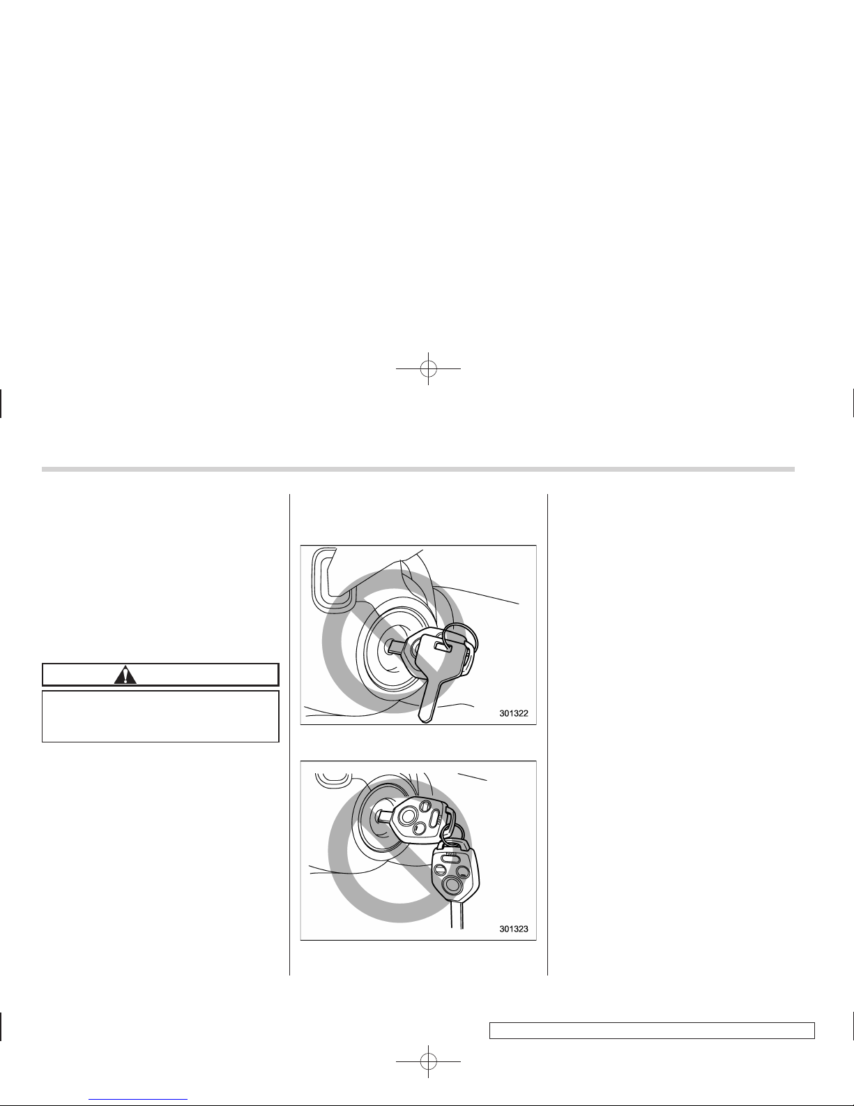
Do not attach a large key holder or
key case to either key. If it banged
against your knees or hands while
you were driving, it could turn the
ignition switch from the “ON” posi-
tion to the “Acc” or “LOCK” position, thereby stopping the engine.
Also, if the key is attached to a
keyholder or to a large bunch of
other keys, centrifugal force may act
on it as the vehicle moves, resulting
in unwanted turning of the ignition
switch.
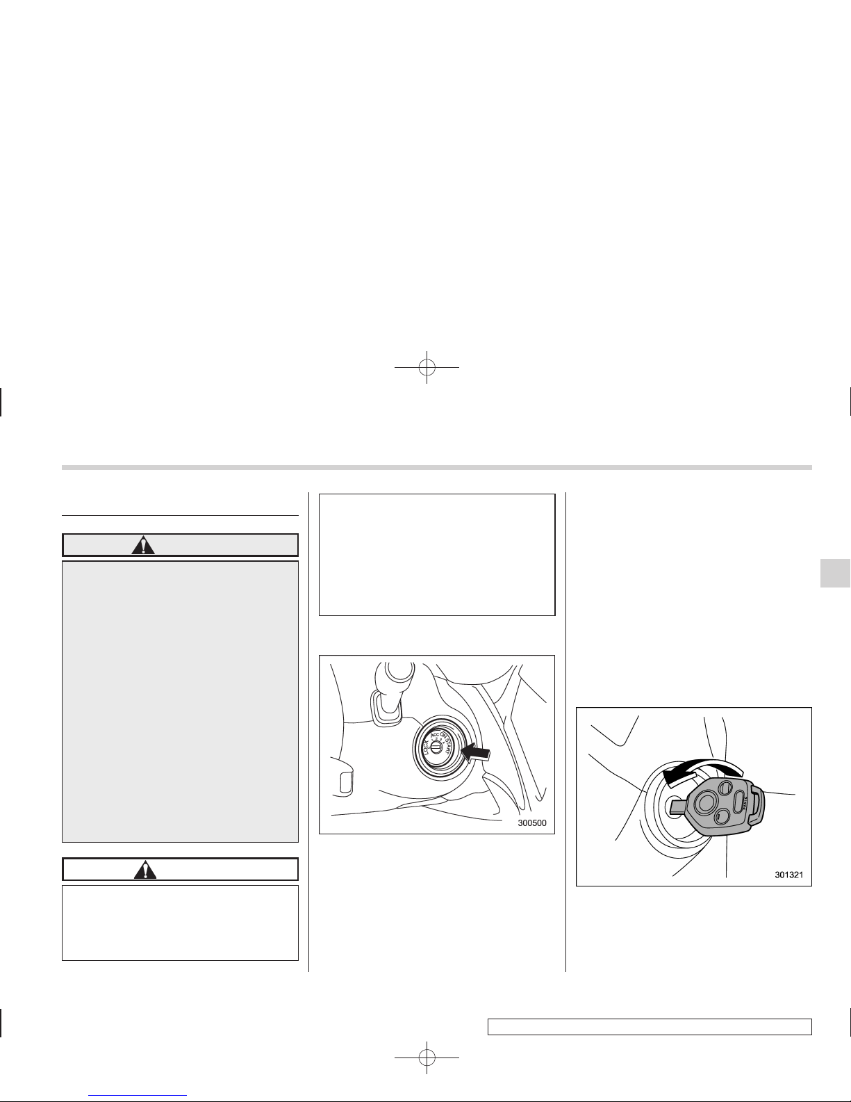
The ignition switch has four positions:
LOCK, Acc, ON and START.
NOTE
. Keep the ignition switch in the
“LOCK” position when the engine is
not running.
. Using electrical accessories for a
long time with the ignition switch in the
“ON” or “Acc” position can cause the
battery to go dead.
. If the ignition switch will not move
from the “LOCK” position to the “Acc”
position, turn the steering wheel
slightly to the left and right as you turn
the ignition switch.
& LOCK
The key can only be inserted or removed
in this position. The ignition switch will lock
the steering wheel when you remove the
key.
If turning the key is difficult, turn the
steering wheel slightly to the right and left
as you turn the key.
The key can be turned from “Acc” to
“LOCK” only when the select lever is in the
“P” position.
Instruments and controls 3-3
– CONTINUED –
Page 4
Black plate (134,1)
北米Model "A3160BE-C" EDITED: 2010/ 11/ 19
3-4 Instruments and controls
& Acc
In this position the electrical accessories
(radio, accessory power outlet, etc.) can
be used.
& ON
This is the normal operating position after
the engine is started.
& START
CAUTION
Do not turn the ignition switch to the
“START” position while the engine
is running.
The engine is started in this position. The
starter cranks the engine to start it. When
the key is released (after the engine has
started), the key automatically returns to
the “ON” position.
If your registered key fails to start the
engine, pull out the key once (the security
indicator light will blink), and then insert
the key in the ignition switch and turn it to
the “START” position and again try to start
the engine.
NOTE
The engine may not start in the following cases.
. The key grip is touching another key
or a metallic key holder.
. The key is near another key that
contains an immobilizer transponder.
. The key is near or touching another
transmitter.
& Key reminder chime
The reminder chime sounds when the
driver’s door opens and the key is in the
“LOCK” or “Acc” positions. The chime
stops when the key is removed from the
ignition switch.
& Ignition switch light
For easy access to the ignition switch in
the dark, the ignition switch light illuminates when the driver’s door is opened.
The light remains on for several seconds
and then gradually turns off after driver’s
door is closed. Also, the light turns off
immediately if the key is turned to the “ON”
position.
Page 5
Black plate (135,1)
北米Model "A3160BE-C" EDITED: 2010/ 11/ 19
Hazard warning flasher
The hazard warning flasher is used to
warn other drivers when you have to park
your vehicle under emergency conditions.
The hazard warning flasher works with the
ignition switch in any position.
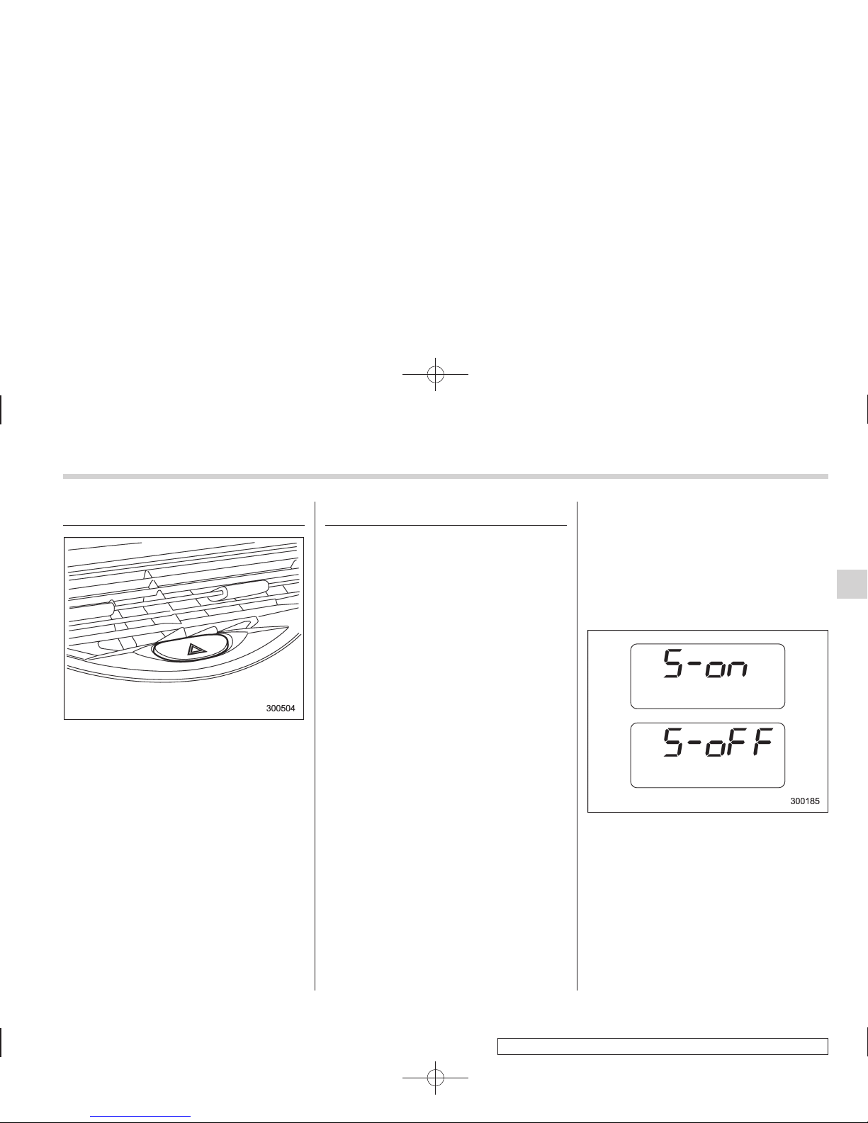
To turn on the hazard warning flasher,
push the hazard warning button on the
instrument panel. To turn off the flasher,
push the button again.
NOTE
When the hazard warning flasher is on,
the turn signals do not work.
Meters and gauges
NOTE
Liquid crystal displays are used in
some of the meters and gauges on
the combination meter. You will find
their indications hard to see if you wear
polarized glasses.
& Combination meter illumina-
tion
When the ignition switch is turned to the
“ON” position, the various parts of the
combination meter are illuminated in the
following sequence.
1. Warning lights, indicator lights, meter
rims, meter needles, odometer, trip meter,
and gauge back lights illuminate.
2. Meter needles and gauges each show
MAX reading.
3. Meter needles and gauges each show
MIN reading.
4. Meter and gauge dials illuminate.
5. Regular illumination (for driving) begins.
NOTE
The above sequence of operations may
not take place if you quickly turn the
ignition switch to start the engine. This
is not a malfunction.
& Canceling the function for
meter needle/gauge movement and combination meter
sequential illumination upon
turning on the ignition switch
It is possible to activate or deactivate the
movement of the meter needles and
gauges and sequential illumination of the
combination meter that takes place when
the ignition switch is turned to the “ON”
position.
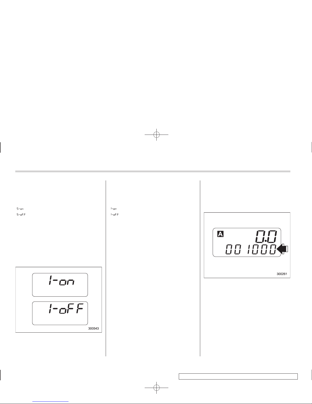
Turn the ignition switch to the “Acc ”
position. With the A trip meter indication
selected, briefly press the trip knob twice.
You can now establish the activated/
deactivated setting for movement of the
Instruments and controls 3-5
– CONTINUED –
Page 6
Black plate (136,1)
北米Model "A3160BE-C" EDITED: 2010/ 11/ 19
3-6 Instruments and controls
meter needles and gauges when the
ignition switch is turned to the “ON”
position. To change the current setting,
press the trip knob for at least 2 seconds.
: Activated
: Deactivated
With the function deactivated, the combination meter illuminates as follows.
1. Warning lights, indicator lights, meter
rims, meter needles, odometer, trip meter,
and gauge back lights illuminate.
2. Meter and gauge dials illuminate.
3. Regular illumination (for driving) begins.
Briefly press the trip knob again. You can
now establish the activated/deactivated
setting for sequential illumination of the
combination meter when the ignition
switch is turned to the “ON” position. To
change the current setting, press the trip
knob for at least 2 seconds.
: Activated
: Deactivated
Briefly press the knob to return to the A trip
meter indication.
If you turn the ignition switch to the
“LOCK” position, turn the ignition switch
to the “ON” position, or open and close the
driver’s door during the setting procedure,
the new setting will be canceled.
Also, if you do not press the trip knob for a
period of 10 seconds, the new setting will
be canceled.
NOTE
. It is not possible to cancel sequential illumination of the combinati on
meter while sequential illumination is
actually taking place. Cancel sequential illumination when regular illumination (for driving) has begun.
. When you open the driver’s door
with the ignition switch in the “LOCK”
position, the meters’ needles and rims
are lit. The illumination stops working
when you shut the driver’s door or
automatically after 30 seconds.
& Speedometer
The speedometer shows the vehicle
speed.
& Odometer
This meter displays the odometer when
the ignition switch is in the “LOCK”, “Acc”
or “ON” position.
The odometer shows the total distance
that the vehicle has been driven.
If you press the trip knob when the ignition
switch is in the “LOCK” or “Acc” position,
the odometer/trip meter will light up. If you
do not press the trip knob within 10
seconds of illumination of the odometer/
trip meter, the odometer/trip meter will turn
off.
Page 7
Black plate (137,1)
北米Model "A3160BE-C" EDITED: 2010/ 11/ 19
The odometer/trip meter will also turn off if
you open and close the driver’sdoor
within 10 seconds of illumination of the
odometer/trip meter.
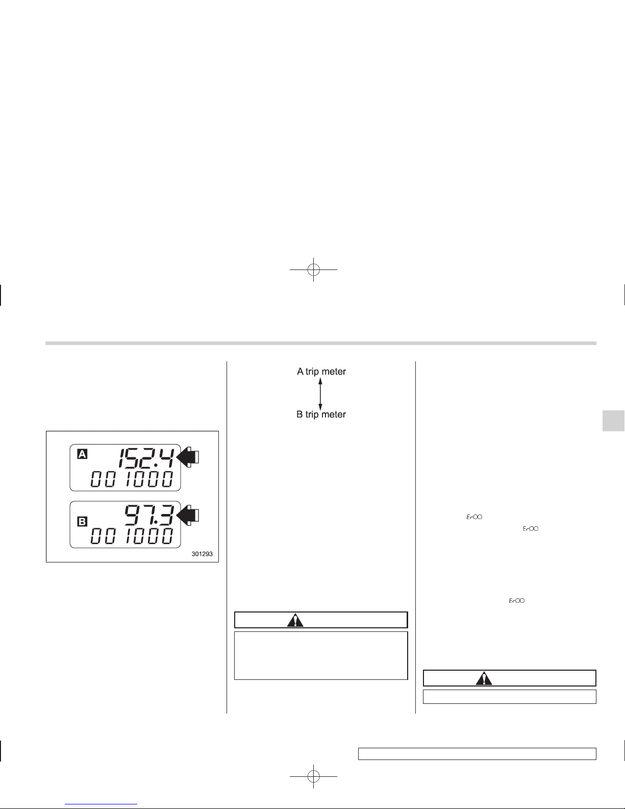
& Double trip meter
This meter displays two trip meters when
the ignition switch is in the “LOCK”, “Acc”
or “ ON” position.
The trip meter shows the distance that the
vehicle has been driven since you last set
it to zero.
To change the mode indication, briefly
push the knob.
Each press of the knob changes the mode
indication alternately.
To set the trip meter to zero, select the A
trip or B trip meter by pushing the knob
and keep the knob pushed for more than 2
seconds.
If you press the trip knob when the ignition
switch is in the “LOCK” position, the
odometer/trip meter will light up. It is
possible to switch between the A trip
meter and B trip meter indications while
the odometer/trip meter is lit up. If you do
not press the trip knob within 10 seconds
of illumination of the odometer/trip meter,
the odometer/trip meter will turn off. Also,
if you open and close the driver’s door
within 10 seconds of illumination of the
odometer/trip meter, the odometer/trip
meter will turn off.
CAUTION
To ensure safety, do not attempt to
change the function of the indicator
during driving, as an accident could
result.
NOTE
If the connection between the combination meter and battery is broken for any
reason such as vehicle maintenance or
fuse replacement, the data recorded on
the trip meter will be lost.
! Vehicle communication system
malfunction indication
The vehicle communication system carries various types of information (vehicle
speed, running conditions, etc.) to control
modules. In the event of a malfunction in
this communication system, the trip meter
will show “
”.
If the trip meter shows “
”, immediately
contact the nearest SUBARU dealer and
have the vehicle communication system
inspected.
NOTE
If you press the trip knob while the trip
meter is showing “
”, the trip meter
indication will appear for 10 seconds.
& Tachometer
The tachometer shows the engine speed
in thousands of revolutions per minute.
CAUTION
Do not operate the engine with the
Instruments and controls 3-7
– CONTINUED –
Page 8
Black plate (138,1)
北米Model "A3160BE-C" EDITED: 2010/ 11/ 19
3-8 Instruments and controls
pointer of the tachometer in the red
zone. This may cause severe damage to the engine.
NOTE
To protect the engine while the select
lever is in the “P” or “N” position, the
engine is controlled so that the engine
speed may not become too high even if
the accelerator pedal is depressed
hard.
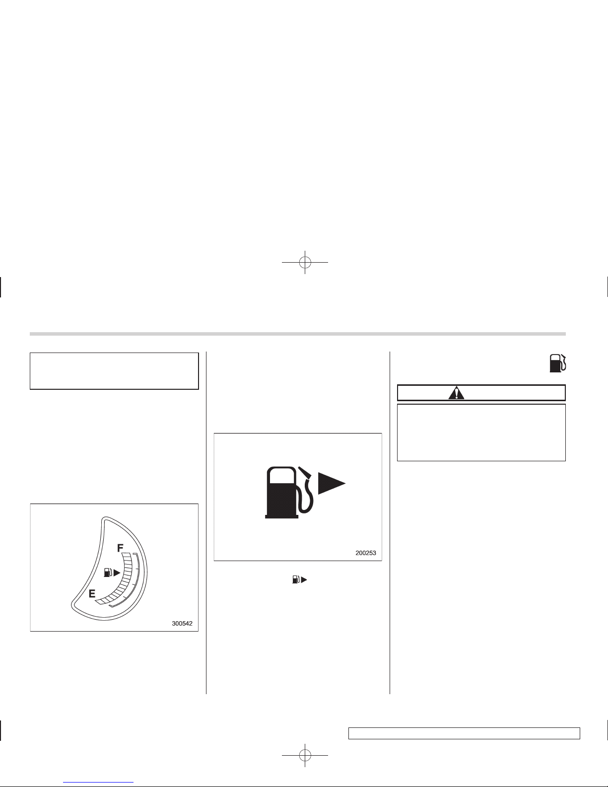
& Fuel gauge
The fuel gauge shows the approximate
amount of fuel remaining in the tank.
The gauge may move slightly during
braking, turning or acceleration due to fuel
level movement in the tank.
If you press the trip knob while the ignition
switch is in the “LOCK” or “Acc” position,
the fuel gauge will light up and indicate the
amount of fuel remaining in the tank.
NOTE
You will see the “ ” sign in the fuel
gauge meter.
This indicates that the fuel filler door
(lid) is located on the right side of the
vehicle.
! Low fuel warning light
CAUTION
Promptly put fuel in the tank whenever the low fuel warning light
illuminates. Engine misfires as a
result of an empty tank could cause
damage to the engine.
The low fuel warning light illuminates
when the tank is nearly empty (approximately 2.6 US gal [10 liters, 2.2 Imp gal]).
It only operates when the ignition switch is
in the “ON” position. When this light
illuminates, fill the fuel tank immediately.
NOTE
This light does not turn off unless the
tank is replenished up to an internal
fuel quantity of approximately 4.0 US
gal (15 liters, 3.3 Imp gal).
Page 9
Black plate (139,1)
北米Model "A3160BE-C" EDITED: 2010/ 11/ 19
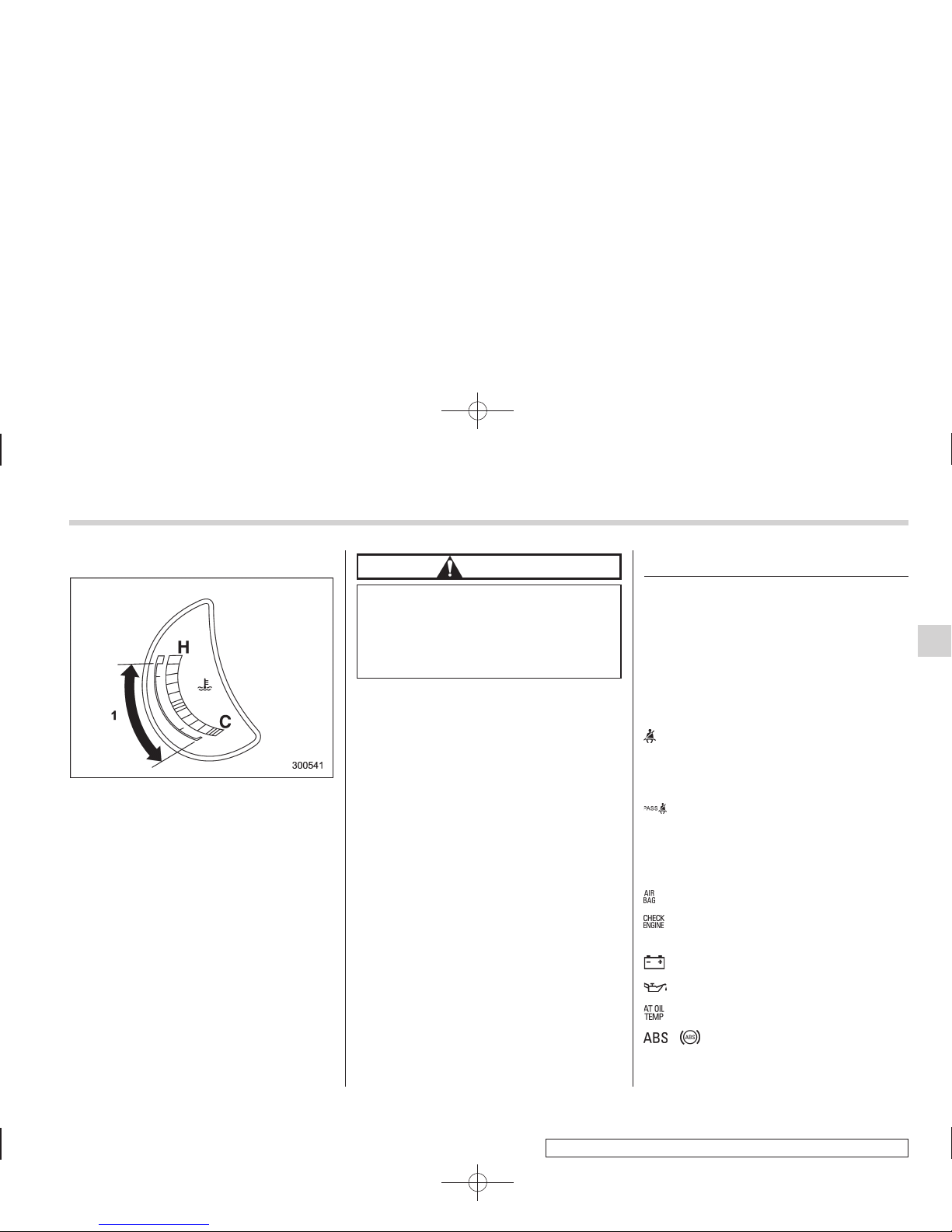
& Temperature gauge
1) Normal operating range
The temperature gauge shows engine
coolant temperature when the ignition
switch is in the “ON” position.
The coolant temperature will vary in
accordance with the outside temperature
and driving conditions.
We recommend that you drive moderately
until the pointer of the temperature gauge
reaches near the middle of the range.
Engine operation is optimum with the
engine coolant at this temperature range.
Also, high revving operation while the
engine is not sufficiently warmed up
should be avoided.
CAUTION
If the pointer exceeds the normal
operating range, safely stop the
vehicle as soon as possible.
Refer to “Engine overheating” F9-
14.
Warning and indicator lights
Several of the warning and indicator lights
illuminate momentarily and then turn off
when the ignition switch is initially turned
to the “ON” position. This permits checking the operation of the bulbs.
Apply the parking brake and turn the
ignition switch to the “ON” position. The
following lights illuminate.
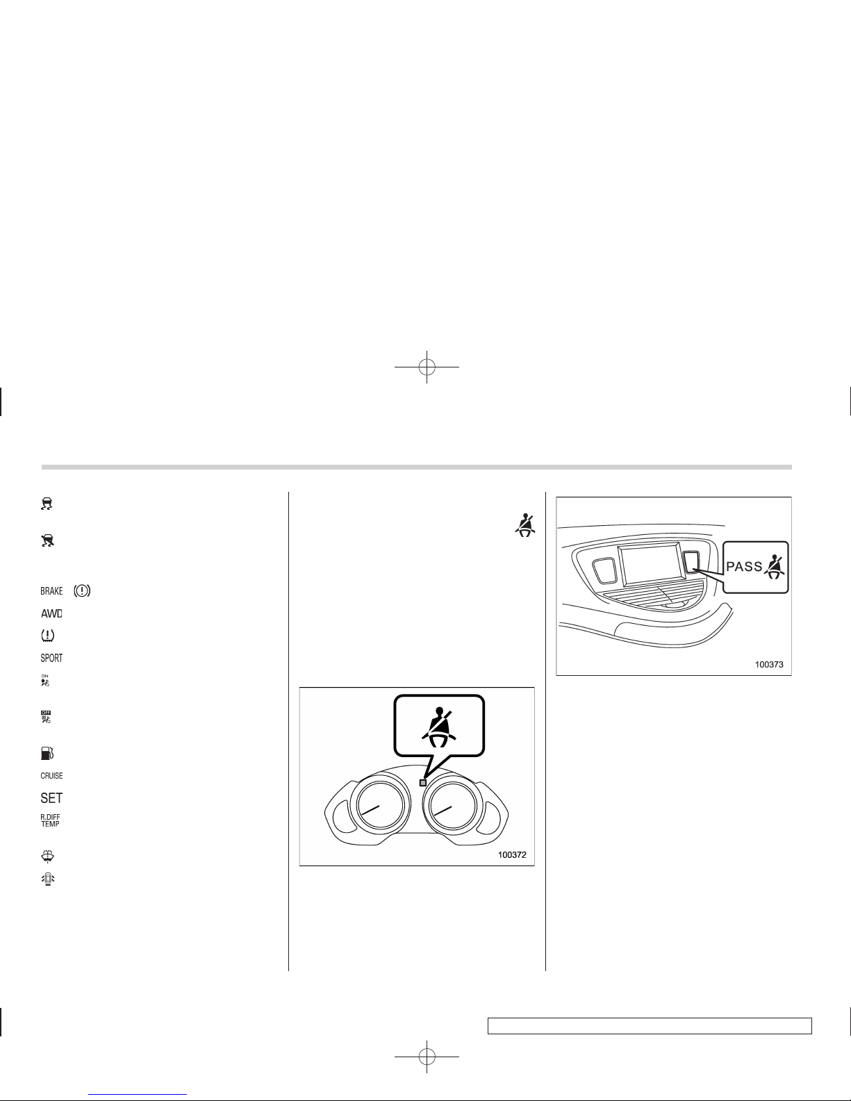
: Driver’s seatbelt warning light
(The seatbelt warning light turns off
only when the driver fastens the
seatbelt.)
: Front passenger’s seatbelt warning
light
(The seatbelt warning light turns off
only when the front seat passenger
fastens the seatbelt.)
: SRS airbag system warning light
: CHECK ENGINE warning light/Mal-
function indicator lamp
: Charge warning light
: Oil pressure warning light
: AT OIL TEMP warning light
/ : ABS warning light
Instruments and controls 3-9
– CONTINUED –
Page 10
Black plate (140,1)
北米Model "A3160BE-C" EDITED: 2010/ 11/ 19
3-10 Instruments and controls
: Vehicle Dynamics Control operation
indicator light
: Vehicle Dynamics Control warning
light/Traction Control system OFF
indicator light
/ : Brake system warning light
: AWD warning light
: Low tire pressure warning light
: SPORT mode indicator light
: Front passenger’s frontal airbag ON
indicator light
: Front passenger’s frontal airbag OFF
indicator light
: Low fuel warning light
: Cruise control indicator light
: Cruise control set indicator light
: Rear differential oil temperature warn-
ing light
: Windshield washer fluid warning light
: Door open warning light
If any lights do not illuminate, it indicates a
burned-out bulb or a malfunction of the
corresponding system.
Consult your authorized SUBARU dealer
for repair.
& Seatbelt warning light
and chime
Your vehicle is equipped with a seatbelt
warning device at the driver’s and front
passenger’s seat.
With the ignition switch turned to the “ON”
position, this device reminds the driver
and front passenger to fasten their seatbelts by illuminating the warning lights in
the locations indicated in the following
illustrations and sounding a chime.
Driver’s warning light
Front passenger’s warning light
! Operation
If the driver and/or front passenger have/
has not yet fastened the seatbelt(s) when
the ignition switch is turned to the “ON”
position, the seatbelt warning light(s) will
flash for 6 seconds, to warn that the
seatbelt(s) is/are unfastened. If the driver’s seatbelt is not fastened, a chime will
also sound simultaneously.
NOTE
. If the driver’s and/or front passen-
ger’s seatbelt(s) is/are still not fastened
6 seconds later, the seatbelt warning
device operates as follows according
to the vehicle speed.
– At speeds lower than approximately 9 mph (15 km/h)
Page 11
Black plate (141,1)
北米Model "A3160BE-C" EDITED: 2010/ 11/ 19
The warning light(s) for unfastened
seatbelt(s) will alternate between
steady illumination and flashing at
15-second intervals. The chime will
not sound.
– At speeds higher than approximately 9 mph (15 km/h)
The warning light(s) for unfastened
seatbelt(s) will alternate between
flashing and steady illumination at
15-second intervals and the chime
will sound while the warning light(s)
is/are flashing.
. It is possible to cancel the warning
operation that follows the 6-second
warning after turning ON the ignition
switch. When the ignition switch is
turned ON next time, however, the
complete sequence of the warning
operation resumes. For further details
about canceling the warning operation,
please contact your SUBARU dealer.
If there is no passenger on the front
passenger’s seat, the seatbelt warning
device for the front passenger’s seat will
be deactivated. The front passenger’s
occupant detection system monitors
whether or not there is a passenger on
the front passenger’s seat. Observe the
following precautions. Failure to do so
may prevent the device from functioning
correctly or cause the device to fail.
. Do not install any accessory such as a
table or TV onto the seatback.
. Do not store a heavy load in the
seatback pocket.
. Do not allow the rear seat occupant to
place his/her hands or legs on the front
passenger’s seatback, or allow him/her to
pull the seatback.
If the seatbelt warning device for the front
passenger’s seat does not function correctly (e.g., it is activated even when the
front passenger’s seat is empty or it is
deactivated even when the front passenger has not fastened his/her seatbelt),
take the following actions.
. Ensure that no article is placed on the
seat other than a child restraint system
and its child occupant.
. Ensure that there is no article left in the
seatback pocket.
If still the seatbelt warning device for front
passenger’s seat does not function correctly after taking relevant corrective actions described above, immediately contact your SUBARU dealer for an inspection.
& SRS airbag system
warning light
When the ignition switch is turned to the
“ON” position, the SRS airbag system
warning light will illuminate for approximately 6 seconds and turn off. This shows
the SRS frontal airbag and SRS side
airbag and SRS curtain airbag and seatbelt pretensioners are in normal operation.
WARNING
If the warning light exhibits any of
the following conditions, there may
be a malfunction in the seatbelt
pretensioners and/or SRS airbag
system. Immediately take your vehicle to your nearest SUBARU dealer
to have the system checked. Unless
checked and properly repaired, the
seatbelt pretensioners and/or SRS
airbags will operate improperly (e.g.
SRS airbags may inflate in a very
minor collision or not inflate in a
severe collision), which may increase the risk of injury.
. Flashing or flickering of the warn-
ing light
. No illumination of the warning
light when the ignition switch is
first turned to the “ON” position
Instruments and controls 3-11
– CONTINUED –
Page 12
Black plate (142,1)
北米Model "A3160BE-C" EDITED: 2010/ 11/ 19
3-12 Instruments and controls
. Continuous illumination of the
warning light
. Illumination of the warning light
while driving
& Front passenger’s frontal
airbag ON and OFF indicators
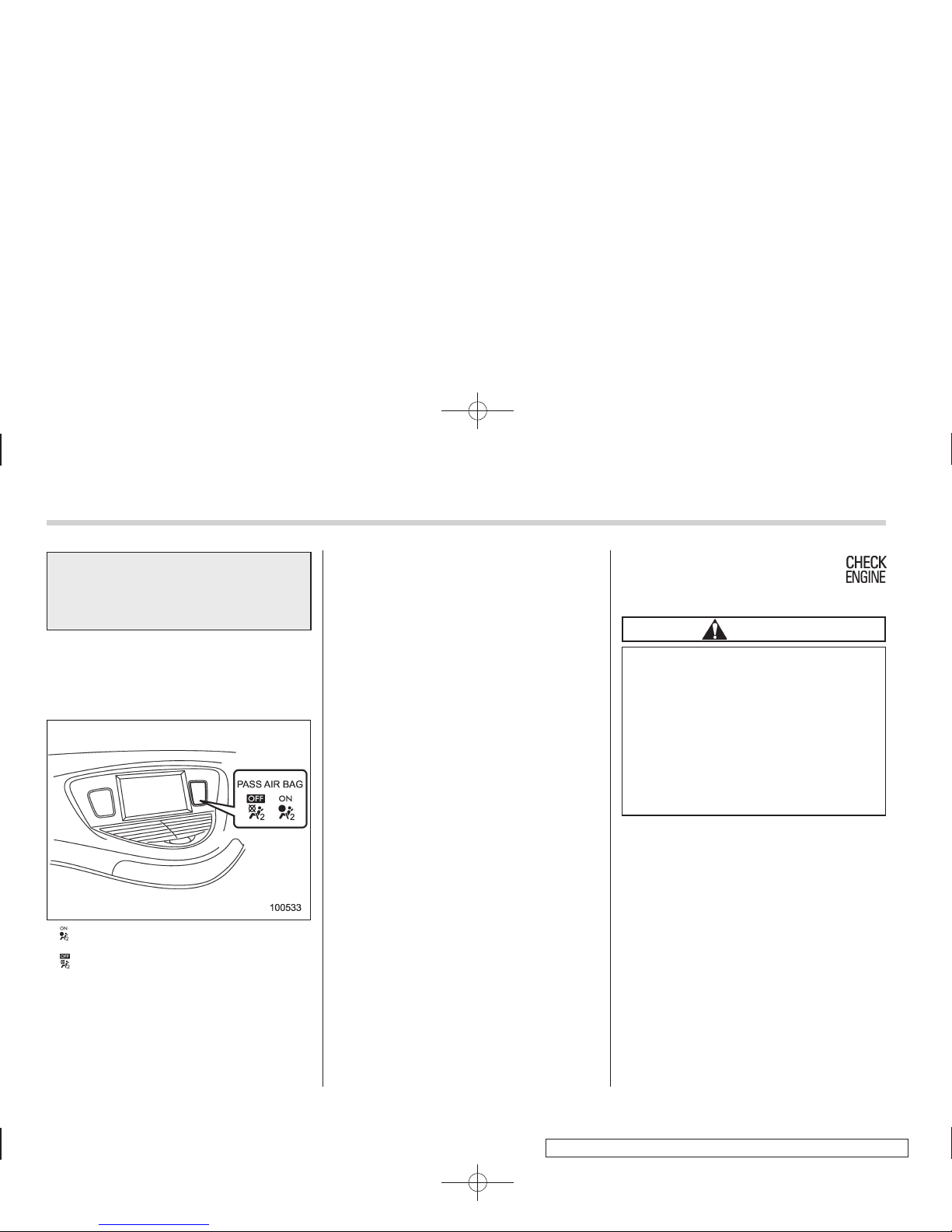
: Front passenger’s frontal airbag ON
indicator
: Front passenger’s frontal airbag OFF
indicator
The front passenger’s frontal airbag ON
and OFF indicators show you the status of
the front passenger’s SRS frontal airbag.
The indicators are located in the center
portion of the dashboard.
When the ignition switch is turned to the
“ON” position, both the ON and OFF
indicators illuminate for 6 seconds during
which time the system is checked. Following the system check, both indicators turn
off for 2 seconds. After that, one of the
indicators illuminates depending on the
status of the front passenger’s SRS frontal
airbag determined by the SUBARU advanced frontal airbag system monitoring.
If the front passenger’s SRS frontal airbag
is activated, the passenger’s frontal airbag
ON indicator will illuminate while the OFF
indicator will remain off.
If the front passenger’s SRS frontal airbag
is deactivated, the passenger’sfrontal
airbag ON indicator will remain off while
the OFF indicator will illuminate.
If both the ON and OFF indicators remain
illuminated or off simultaneously, the
system is malfunctioning. Contact your
SUBARU dealer immediately for an inspection.
& CHECK ENGINE warn-
ing light/Malfunction indicator lamp
CAUTION
If the CHECK ENGINE light illuminates while you are driving, have
your vehicle checked/repaired by
your SUBARU dealer as soon as
possible. Continued vehicle operation without having the emission
control system checked and repaired as necessary could cause
serious damage, which may not be
covered by your vehicle’s warranty.
If this light illuminates steadily or blinks
while the engine is running, it may indicate
that there is a problem or potential
problem somewhere in the emission control system.
! If the light illuminates steadily
If the light illuminates steadily while driving
or does not turn off after the engine starts,
an emission control system malfunction
has been detected.
You should have your vehicle checked by
an authorized SUBARU dealer immediately.
Page 13
Black plate (143,1)
北米Model "A3160BE-C" EDITED: 2010/ 11/ 19
NOTE
This light also illuminates when the fuel
filler cap is not tightened until it clicks.
If you have recently refueled your vehicle,
the cause of the CHECK ENGINE warning
light/malfunction indicator lamp illuminating could be a loose or missing fuel filler
cap. Remove the cap and retighten it until
it clicks. Make sure nothing is interfering
with the sealing of the cap. Tightening the
cap will not make the CHECK ENGINE
warning light turn off immediately. It may
take several driving trips. If the light does
not turn off, take your vehicle to your
authorized SUBARU dealer immediately.
! If the light is blinking
If the light is blinking while driving, an
engine misfire condition has been detected which may damage the emission
control system.
To prevent serious damage to the emission control system, you should do the
following.
. Reduce vehicle speed.
. Avoid hard acceleration.
. Avoid steep uphill grades.
. Reduce the amount of cargo, if possi-
ble.
. Stop towing a trailer as soon as
possible.
The CHECK ENGINE warning light may
stop blinking and illuminate steadily after
several driving trips. You should have your
vehicle checked by an authorized
SUBARU dealer immediately.
& Charge warning light
If this light illuminates when the engine is
running, it may indicate that the charging
system is not working properly.
If the light illuminates while driving or does
not turn off after the engine starts, stop the
engine at the first safe opportunity and
check the alternator belt. If the belt is
loose, broken or if the belt is in good
condition but the light remains illuminated,
contact your nearest SUBARU dealer
immediately.
& Oil pressure warning
light
CAUTION
Do not operate the engine with the
oil pressure warni ng light illuminated. This may cause serious engine damage.
If this light illuminates when the engine is
running, it may indicate that the engine oil
pressure is low and the lubricating system
is not working properly.
If the light illuminates while driving or does
not turn off after the engine starts, stop the
engine at the first safe opportunity and
check the engine oil level. If the oil level is
low, add oil immediately. If the engine oil is
at the proper level but the light remains
illuminated, contact your nearest
SUBARU dealer immediately.
& AT OIL TEMP warning
light
The AT oil temperature warning light “AT
OIL TEMP” illuminates when the ignition
switch is turned to the “ON” position and
turns off after approximately 2 seconds.
If this light illuminates when the engine is
running, it may indicate that the automatic
transmission fluid temperature is too hot.
If the light illuminates while driving, immediately stop the vehicle in a safe place
and let the engine idle until the warning
light turns off.
! Automatic transmission control
system warning
If the light flashes after the engine starts, it
may indicate that the automatic transmission control system is not working properly. Contact your nearest SUBARU dealer for service immediately.
Instruments and controls 3-13
– CONTINUED –
Page 14
Black plate (144,1)
北米Model "A3160BE-C" EDITED: 2010/ 11/ 19
3-14 Instruments and controls
& Rear differential oil
temperature warning
light
CAUTION
Reduce vehicle speed and park the
vehicle in a safe place as soon as
possible if the R.DIFF TEMP light
illuminates. Continued driving with
this light illuminated can damage
the rear differential and other parts
of the powertrain.
If this light illuminates when the engine is
running, it may indicate that the rear
differential oil temperature is too hot.
If the light illuminates while driving, reduce
vehicle speed and stop the vehicle at the
nearest safe place.
Park the vehicle for several minutes. After
the light turns off, you can start driving.
If the light does not turn off, contact the
nearest SUBARU dealer for service.
NOTE
. If the tire pressures are not correct
and/or the tires are not all the same
size and brand, the rear differential will
be heavily loaded when the vehicle is
driven, resulting in an abnormally high
oil temperature.
. The rear differential oil will deteriorate if its temperature increases enough for the rear differential oil temperature warning light to illuminate. It is
advisable to have the rear differential
oil replaced as soon as possible.
& Low tire pressure
warning light
When the ignition switch is turned to the
“ON” position, the low tire pressure warning light will illuminate for approximately 2
seconds to check that the tire pressure
monitoring system (TPMS) is functioning
properly. If there is no problem and all tires
are properly inflated, the light will turn off.
Each tire, including the spare (if provided),
should be checked monthly when cold
and inflated to the inflation pressure
recommended by the vehicle manufacturer on the vehicle placard or tire inflation
pressure label. (If your vehicle has tires of
a different size than the size indicated on
the vehicle placard or tire inflation pressure label, you should determine the
proper tire inflation pressure for those
tires.)
As an added safety feature, your vehicle
has been equipped with a tire pressure
monitoring system (TPMS) that illuminates
a low tire pressure telltale when one or
more of your tires is significantly underinflated. Accordingly, when the low tire
pressure telltale illuminates, you should
stop and check your tires as soon as
possible, and inflate them to the proper
pressure. Driving on a significantly underinflated tire causes the tire to overheat and
can lead to tire failure. Under-inflation also
reduces fuel efficiency and tire tread life,
and may affect the vehicle’s handling and
stopping ability.
Please note that the TPMS is not a
substitute for proper tire maintenance,
and it is the driver’s responsibility to
maintain correct tire pressure, even if
under-inflation has not reached the level
to trigger illumination of the TPMS low tire
pressure telltale.
Your vehicle has also been equipped with
a TPMS malfunction indicator to indicate
when the system is not operating properly.
The TPMS malfunction indicator is combined with the low tire pressure telltale.
When the system detects a malfunction,
the telltale will flash for approximately one
minute and then remain continuously
illuminated. This sequence will continue
upon subsequent vehicle start-ups as long
as the malfunction exists. When the
malfunction indicator is illuminated, the
system may not be able to detect or signal
low tire pressure as intended. TPMS
Page 15
Black plate (145,1)
北米Model "A3160BE-C" EDITED: 2010/ 11/ 19
malfunctions may occur for a variety of
reasons, including the installation of replacement or alternate tires or wheels on
the vehicle that prevent the TPMS from
functioning properly. Always check the
TPMS malfunction telltale after replacing
one or more tires or wheels on your
vehicle to ensure that the replacement or
alternate tires and wheels allow the TPMS
to continue to function properly.
Should the warning light illuminate steadily after blinking for approximately one
minute, have the system inspected by
your nearest SUBARU dealer as soon as
possible.
WARNING
If this light does not illuminate
briefly after the ignition switch is
turned ON or the light illuminates
steadily after blinking for approximately one minute, you should have
your Tire Pressure Monitoring System checked at a SUBARU dealer as
soon as possible.
If this light illuminates while driving,
never brake suddenly and keep
driving straight ahead while gradually reducing speed. Then slowly
pull off the road to a safe place.
Otherwise an accident involving
serious vehicle damage and serious
personal injury could occur.
If this light still illuminates while
driving after adjusting the tire pressure, a tire may have significant
damage and a fast leak that causes
the tire to lose air rapidly. If you have
a flat tire, replace it with a spare tire
as soon as possible.
When a spare tire is mounted or a
wheel rim is replaced without the
original pressure sensor/transmitter
being transferred, the Low tire pressure warning light will illuminate
steadily after blinking for approximately one minute. This indicates
that the TPMS is unable to monitor
all four road wheels. Contact your
SUBARU dealer as soon as possible
for tire and sensor replacement and/
or system resetting. If the light
illuminates steadily after blinking
for approximately one minute,
promptly contact a SUBARU dealer
to have the system inspected.
CAUTION
The tire pressure monitoring system
is NOT a substitute for manually
checking tire pressure. The tire
pressure should be checked periodically (at least monthly) using a
tire gauge. After any change to tire
pressure(s), the tire pressure monitoring system will not re-check tire
inflation pressures until the vehicle
is first driven more than 20 mph (32
km/h). Therefore, after adjusting the
tire pressures, increase the vehicle
speed to at least 20 mph (32 km/h) to
start the TPMS re-checking of the
tire inflation pressures. If the tire
pressures are now above the severe
low pressure threshold, the low tire
pressure warning light should turn
off a few minutes later. Therefore, be
sure to install the specified size for
the front and rear tires.
& ABS warning light
The ABS warning light illuminates when
the ignition switch is turned to the “ON”
position and turns off after approximately 2
seconds.
This is an indication that the ABS system
is working properly.
CAUTION
If the warning light behaves as
follows, the ABS system may not
Instruments and controls 3-15
– CONTINUED –
Page 16
Black plate (146,1)
北米Model "A3160BE-C" EDITED: 2010/ 11/ 19
3-16 Instruments and controls
work properly.
When the warning light illuminates,
the ABS function shuts down; however, the conventional brake system
continues to operate normally.
. The warning light does not illu-
minate when the ignition switch
is turned to the “ON” position.
. The warning light illuminates
when the ignition switch is
turned to the “ON” position, but
it does not turn off even when the
vehicle speed exceeds approximately 8 mph (12 km/h).
. The warning light illuminates dur-
ing driving.
If any of these conditions occur,
have the ABS system repaired at
the first available opportunity by
your SUBARU dealer.
The ABS warning light illuminates together with the brake system warning light
if the EBD system becomes malfunctioning. For further details of the EBD system
malfunction warning, refer to “Brake system warning light” F3-16.
NOTE
If the warning light behavior is as
described in the following, the ABS
system may be considered normal.
. The warning light illuminates right
after the engine is started but turns off
immediately, remaining off.
. The warning light remains illuminated after the engine has been started,
but it turns off when the vehicle speed
reaches approximately 8 mph (12
km/h).
. The warning light illuminates during
driving, but it turns off immediately and
remains off.
When driving with an insufficient battery
voltage such as when the engine is jump
started, the ABS warning light may illuminate. This is due to the low battery voltage
and does not indicate a malfunction.
When the battery becomes fully charged,
the light will turn off.
& Brake system
warning light
WARNING
. Driving with the brake system
warning light illuminated is dangerous. This indicates your brake
system may not be working
properly. If the light remains
illuminated, have the brakes inspected by a SUBARU dealer
immediately.
. If at all in doubt about whether
the brakes are operating properly, do not drive the vehicle.
Have your vehicle towed to the
nearest SUBARU dealer for repair.
This light has the following three functions.
! Parking brake warning
The light illuminates with the parking
brake applied while the ignition switch is
in the “ON” position. It turns off when the
parking brake is fully released.
! Brake fluid level warning
This light illuminates when the brake fluid
level has dropped to near the “MIN” level
of the brake fluid reservoir with the ignition
switch in the “ON” position and with the
parking brake fully released.
If the brake system warning light should
illuminate while driving (with the parking
brake fully released and with the ignition
switch positioned in “ON”), it could be an
indication of leaking of brake fluid or worn
brake pads. If this occurs, immediately
stop the vehicle at the nearest safe place
and check the brake fluid level. If the fluid
level is below the “MIN” mark in the
reservoir, do not drive the vehicle. Have
Page 17
Black plate (147,1)
北米Model "A3160BE-C" EDITED: 2010/ 11/ 19
the vehicle towed to the nearest SUBARU
dealer for repair.
! Electronic Brake Force Distribution
(EBD) system warning
The brake system warning light also
illuminates if a malfunction occurs in the
EBD system. In that event, it illuminates
together with the ABS warning light.
The EBD system may be malfunctioning if
the brake system warning light and ABS
warning light illuminate simultaneously
during driving.
Even if the EBD system fails, the conventional braking system will still function.
However, the rear wheels will be more
prone to locking when the brakes are
applied harder than usual and the vehicle’s motion may therefore become somewhat harder to control.
If the brake system warning light and ABS
warning light illuminate simultaneously,
take the following steps.
1. Stop the vehicle in the nearest safe,
flat place.
2. Shut down the engine, apply the
parking brake, and then restart it.
3. Release the parking brake. If both
warning lights turn off, the EBD system
may be malfunctioning.
Drive carefully to the nearest SUBARU
dealer and have the system inspected.
4. If both warning lights illuminate again
and remain illuminated after the engine
has been restarted, shut down the engine
again, apply the parking brake, and check
the brake fluid level.
5. If the brake fluid level is not below the
“MIN” mark, the EBD system may be
malfunctioning. Drive carefully to the
nearest SUBARU dealer and have the
system inspected.
6. If the brake fluid level is below the
“MIN” mark, DO NOT drive the vehicle.
Instead, have the vehicle towed to the
nearest SUBARU dealer for repair.
& Low fuel warning light
CAUTION
Immediately put fuel in the tank
whenever the low fuel warning light
illuminates. Engine misfires as a
result of an empty tank could cause
damage to the engine.
The low fuel warning light illuminates
when the tank is nearly empty approximately 2.6 US gal (10 liters, or 2.2 Imp
gal). It only operates when the ignition
switch is in the “ON” position. When this
light illuminates, fill the fuel tank immediately.
NOTE
This light does not turn off unless the
tank is replenished up to an internal
fuel quantity of approximately 4.0 US
gal (15 liters, 3.3 Imp gal).
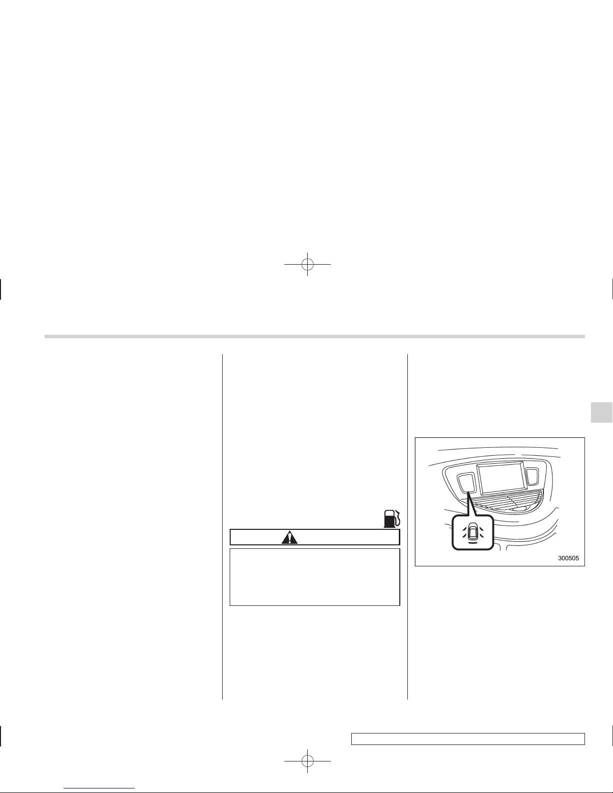
& Door open warning light
The indicators are located in the center
portion of the dashboard.
When any of the doors or the rear gate is
not fully closed, it is indicated by the
corresponding part of the door open
warning light.
Always make sure this light is out before
you start to drive.
Instruments and controls 3-17
– CONTINUED –
Page 18
Black plate (148,1)
北米Model "A3160BE-C" EDITED: 2010/ 11/ 19
3-18 Instruments and controls
& Windshield washer
fluid warning light
This light illuminates when the fluid level in
the windshield washer fluid tank falls to
the lower limit (approximately 0.6 US qt,
0.6 liter, 0.5 Imp qt).
& All-Wheel Drive warn-
ing light
WARNING
Continued driving with the AWD
warning light flashing can lead to
powertrain damage. If the AWD
warning light flashes, promptly park
in a safe place then check whether
all four tires are the same diameter
and whether any of the tires has a
puncture or has lost air pressure for
some other reason.
The All-Wheel Drive warning light illuminates when the ignition switch is turned to
the “ON” position and turns off after the
engine has started.
This light flashes if the vehicle is driven
with tires of different diameters fitted on its
wheels or with the air pressure excessively low in any of its tires.
& Vehicle Dynamics
Control operation indicator light
This light illuminates when the ignition
switch is ON and turns off approximately 2
seconds later.
It blinks when the skid suppression function is activated. It illuminates when only
the traction control function is operating.
The Vehicle Dynamics Control system is
probably malfunctioning under any of the
following conditions. Have your vehicle
checked at a SUBARU dealer immediately.
. The light does not illuminate when the
ignition switch is turned to the “ON ”
position.
. The light does not turn off even after a
period of approximately 2 seconds after
the ignition switch has been turned to the
“ON” position.
& Vehicle Dynamics
Control warning light/
Traction Control system
OFF indicator light
This warning light has both the function of
indicating malfunctions in the Vehicle
Dynamics Control system and the function
of indicating that the Traction Control
system has been deactivated.
It illuminates in the event of a malfunction
in the system or when the system is not
operating.
This warning light illuminates when the
ignition switch is turned to the “ON”
position and turns off several seconds
after engine startup. It indicates that the
Vehicle Dynamics Control system is in
normal operation.
! Vehicle Dynamics Control warning
light
The Vehicle Dynamics Control system is
probably inoperative under any of the
following conditions. Have your vehicle
checked at a SUBARU dealer immediately.
. The warning light does not illuminate
when the ignition switch is turned to the
“ON” position.
. The warning light illuminates while the
vehicle is running.
. If the electrical circuit of the Vehicle
Dynamics Control system itself becomes
malfunctioning, the warning light only
illuminates. At this time, the ABS (Antilock Brake System) remains fully operational.
. The warning light illuminates when the
electronic control system of the ABS/
Vehicle Dynamics Control system be-
Page 19
Black plate (149,1)
北米Model "A3160BE-C" EDITED: 2010/ 11/ 19
comes malfunctioning.
The Vehicle Dynamics Control system
provides its ABS control through the
electrical circuit of the ABS system.
Accordingly, if the ABS is inoperative, the
Vehicle D ynami cs Control system becomes unable to provide ABS control. As
a result, the Vehicle Dynamics Control
system also becomes inoperative, causing the warning light to illuminate. Though
both the Vehicle Dynamics Control and
ABS systems are inoperative in this case,
the ordinary functions of the brake system
are still available. You will be safe while
driving with this condition, but have your
vehicle checked at a SUBARU dealer as
soon as possible.
NOTE
If the warning light behavior is as
shown in the following, the Vehicle
Dynamics Control system may be considered normal.
. The warning light illuminates right
after the engine is started but turns off
immediately, remaining off.
. The warning light illuminates after
engine startup and turns off while the
vehicle is subsequently being driven.
. The warning light illuminates during
driving, but it turns off immediately and
remains off.
! Traction Control system OFF indi-
cator light
. It illuminates when the Traction Control
system OFF switch is pressed.
. It also illuminates when the Traction
Control system is deactivated.
NOTE
. The light may remain illuminated for
a while after the engine has been
started, especially in cold weather. This
does not indicate the existence of a
problem. The light should turn off as
soon as the engine has warmed up.
. The indicator light illuminates when
the engine has developed a problem
and the CHECK ENGINE warning light/
Malfunction indicator lamp illuminates.
The Vehicle Dynamics Control system is
probably malfunctioning under the following condition. Have your vehicle checked
at a SUBARU dealer as soon as possible.
. The light does not turn off even after
the lapse of several minutes (the engine
has warmed up) after the engine has
started.
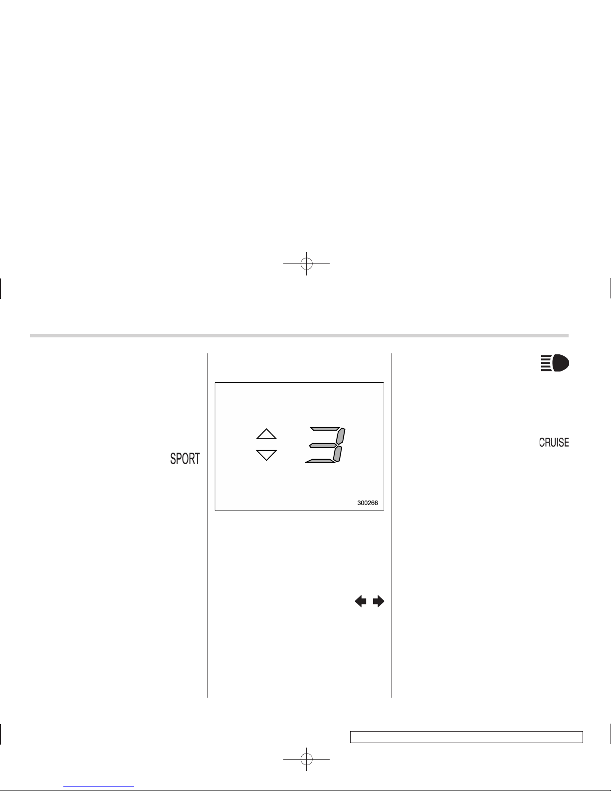
& Security indicator light
The indicators are located in the center
portion of the dashboard.
This indicator light shows the status of the
alarm system. It also indicates operation
of the immobilizer system.
! Alarm system
It blinks to show the driver the operational
status of the alarm system. For detailed
information, refer to “Alarm system” F2-
16.
! Immobilizer system
This light blinks approximately 60 seconds
after the ignition switch is turned from
“ON” position to the “Acc” or “LOCK”
position or immediately after the key is
pulled out. Refer to “Immobilizer” F2-3.
Instruments and controls 3-19
– CONTINUED –
Page 20
Black plate (150,1)
北米Model "A3160BE-C" EDITED: 2010/ 11/ 19
3-20 Instruments and controls
If the indicator light does not flash, it may
indicate that immobilizer system may be
malfunctioning. Contact your nearest
SUBARU dealer immediately.
In the event that an unauthorized key (for
example, an unauthorized duplicate) is
used, the security indicator light illuminates.
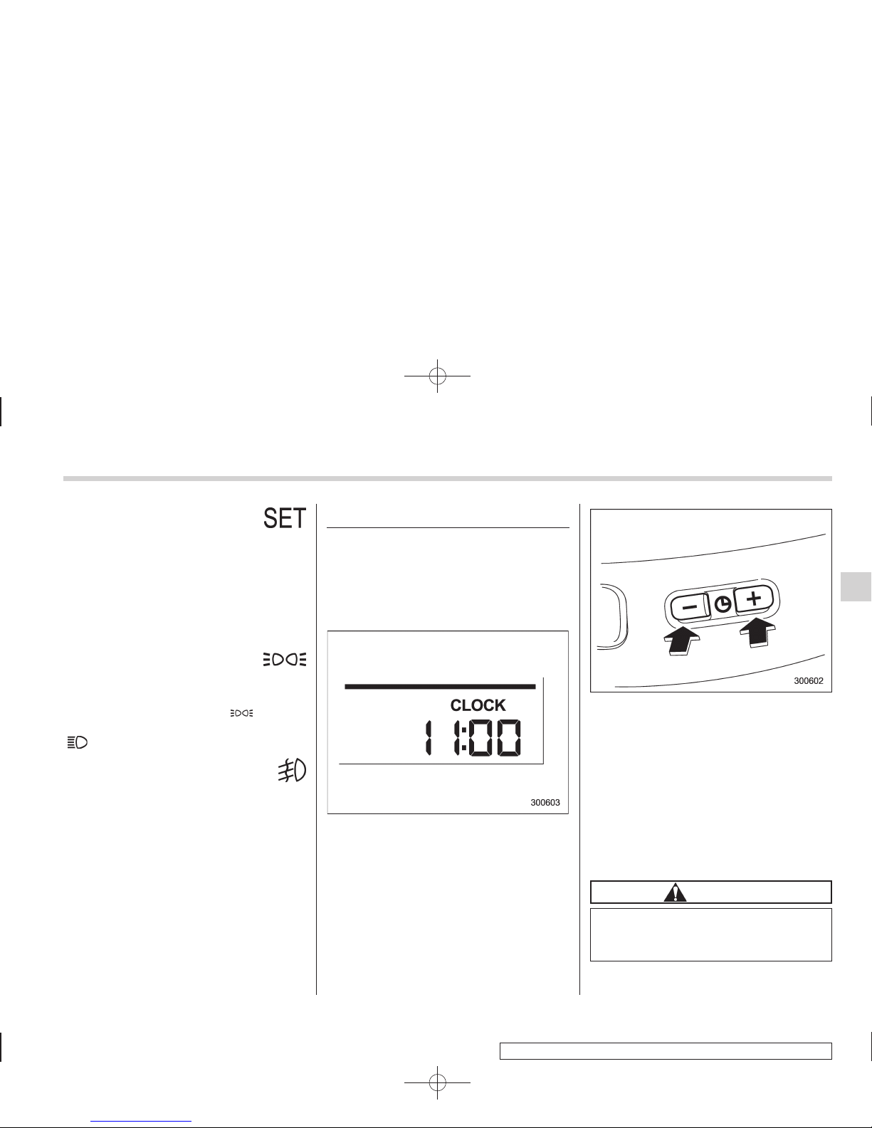
& SPORT mode indicator
light
This light illuminates when the ignition
switch is turned to the “ON” position and
turns off after the engine has started.
When the select lever is moved to the
manual gate, the SPORT mode is selected and the indicator light illuminates.
Refer to “SPORT mode” F7-18.
& Select lever/Gear position in-
dicator
The select lever/gear position indicator
shows the position of the select lever.
When manual mode is selected, the gear
position indicator shows the current gear
position and the upshift/downshift indicator illuminates. Refer to “Automatic transmission” F7-12.
& Turn signal indicator
lights
These lights show the operation of the turn
signal or lane change signal.
If the indicator lights do not blink or blink
rapidly, the turn signal bulb may be burned
out. Replace the bulb as soon as possible.
Refer to “Replacing bulbs” F11-37.
& High beam indicator
light
This light shows that the headlights are in
the high beam mode.
This indicator light also illuminates when
the headlight flasher is operated.
& Cruise control indica-
tor light
The cruise control indicator light illuminates when the ignition switch is turned to
the “ON” position and turns off after
approximately 3 seconds.
This light illuminates when the “CRUISE”
main switch is pressed.
NOTE
. If you move the cruise control lever
or press the main switch button while
turning the ignition switch “ON”, the
cruise control function is deactivated
and the cruise control indicator light
flashes. To reactivate the cruise control
function, turn the ignition switch back
to the “Acc” or “LOCK” position, and
then turn it again to the “ON” position.
. If this indicator light and the CHECK
ENGINE warning light/malfunction indicator lamp flash simultaneously during driving, have the vehicle checked
by your nearest SUBARU dealer.
Page 21
Black plate (151,1)
北米Model "A3160BE-C" EDITED: 2010/ 11/ 19
& Cruise control set in-
dicator light
The cruise control set indicator light
illuminates when the ignition switch is
turned to the “ON” position and turns off
after approximately 3 seconds.
This light illuminates when vehicle speed
has been set.
& Headlight indicator
light
This indicator light illuminates when the
light switch is turned to the “
” position
(to turn on the parking lights) or to the
“
” position (to turn on the headlights).
& Front fog light indicator
light
This indicator light illuminates while the
front fog lights are illuminated.
Clock
NOTE
If your vehicle is equipped with a
genuine SUBARU navigation system,
refer to the Owner’s Manual supplement for the navigation system.
The clock shows the time while the
ignition switch is in the “Acc” or “ON”
position.
To adjust the time shown by the clock,
press the “+” button or the “−” button. The
indicated time will change in 1-minute
increments. If you keep the button
pressed, the rate at which the indicated
time changes will speed up.
When you keep either the “+” or “−” button
pressed, time change will pause for 1
second at the end of each 30-minute
change. The clock will start going forward
or backward again quickly after this 1second pause.
CAUTION
To ensure safety, do not attempt to
set the time during driving, as an
accident could result.
Instruments and controls 3-21
Page 22
Black plate (152,1)
北米Model "A3160BE-C" EDITED: 2010/ 11/ 19
3-22 Instruments and controls
Outside temperature indicator
NOTE
If your vehicle is equipped with a
genuine SUBARU navigation system,
refer to the Owner’s Manual supplement for the navigation system.
U.S.-spec. models
Except U.S.-spec. models
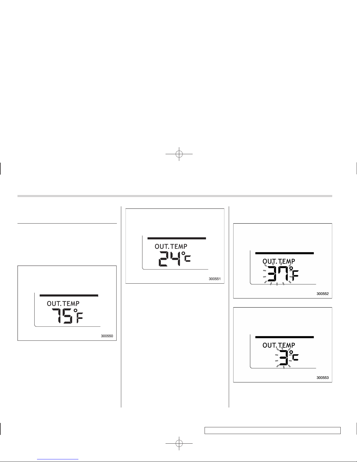
The outside temperature indicator shows
the outside temperature in a range from
−22 to 1228F(−30 to 508C) when the
ignition switch is in the “ON” position.
The indicator can give a false reading
under any of the following conditions.
. When there is too much sun.
. During idling; while running at low
speeds in a traffic jam; when the engine
is restarted immediately following a shutdown.
. When the actual outside temperature
falls outside the specified indicator range.
& Low outside temperature
warning
U.S.-spec. models
Except U.S.-spec. models
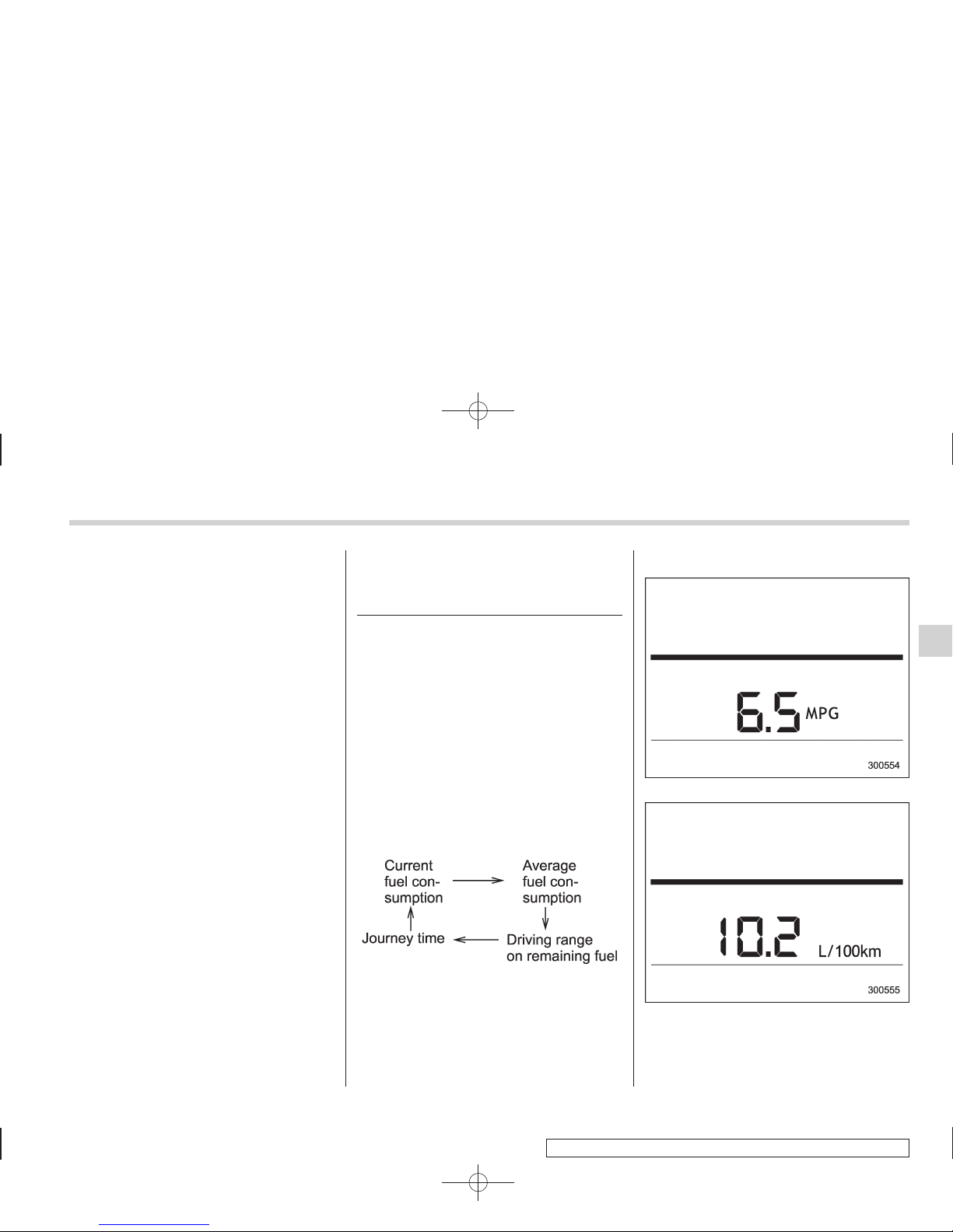
When the outside temperature drops to
378F(38C) or lower, the temperature
Page 23
Black plate (153,1)
北米Model "A3160BE-C" EDITED: 2010/ 11/ 19
indication flashes to show that the road
surface may be frozen.
If the outside temperature drops to 378F
(38C) or lower while the display is giving
an indication other than the outside
temperature, the display switches to the
outside temperature indication and flashes
for 5 seconds before returning to its
original indication.
If the display is already indicating an
outside temperature of 378F(38C) or lower
when the ignition switch is turned to the
“ON” position, the indication does not
flash.
NOTE
The outside temperature indication
may differ from the actual outside
temperature. The road surface freeze
warning indication should be treated
only as a guide. Be sure to check the
condition of the road surface before
driving.
Multi fun ction display (vehicles without a genuine
SUBARU navigation system)
NOTE
. If your vehicle is equipped with a
genuine SUBARU navigation system,
refer to the Owner’s Manual supplement for the navigation system.
. A liquid crystal display is used in the
multi function display. You will find its
indications hard to see if you wear
polarized glasses.
Withtheignitionswitchinthe“ ON”
position, each successive push of the
“INFO” button toggles the display in the
following sequence.
Press the “INFO” button for more than 1
second to turn off the display. The display
will turn on again if you press either the
“INFO” button or “AUDIO” button.
& Current fuel consumption
U.S.-spec. models
Except U.S.-spec. models
This indication shows the rate of fuel
consumption at the present moment.
Instruments and controls 3-23
– CONTINUED –
Page 24
Black plate (154,1)
北米Model "A3160BE-C" EDITED: 2010/ 11/ 19
3-24 Instruments and controls
& Average fuel consumption
U.S.-spec. models
Except U.S.-spec. models
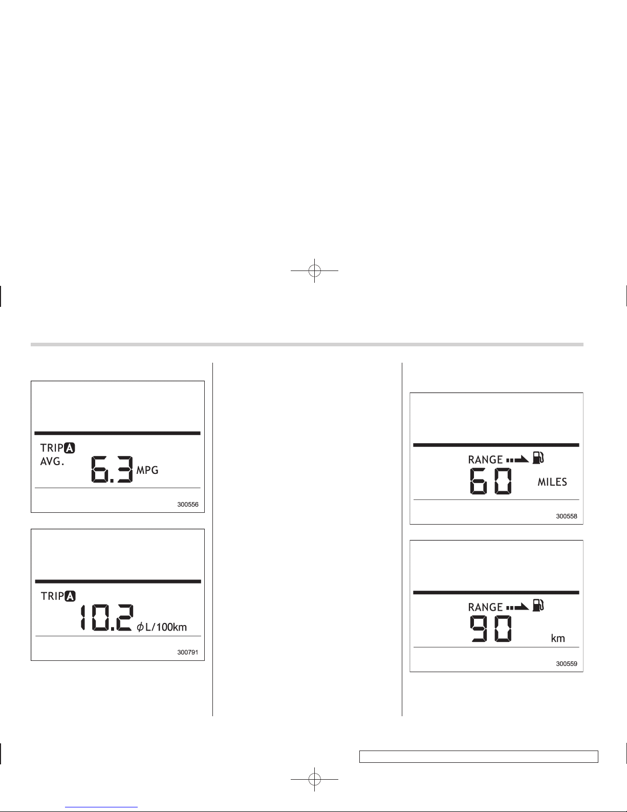
This indication shows the average rate of
fuel consumption since the trip meter was
last reset.
Pressing the trip knob toggles the indication between the average fuel consumption corresponding to the A trip meter
indication and the average fuel consumption corresponding to the B trip meter
indication.
When either of the trip meter indications is
reset, the corresponding average fuel
consumption value is also reset.
NOTE
. The indicated values vary in accordance with changes in the vehicle’s
running conditions. Also, the indicated
values may differ slightly from the
actual values and should thus be
treated only as a guide.
. When either trip meter indication is
reset, the average fuel consumption
corresponding to that trip meter indication is not shown until the vehicle has
subsequently covered a distance of 1
mile (or 1 km).
& Driving range on remaining
fuel
U.S.-spec. models
Except U.S.-spec. models
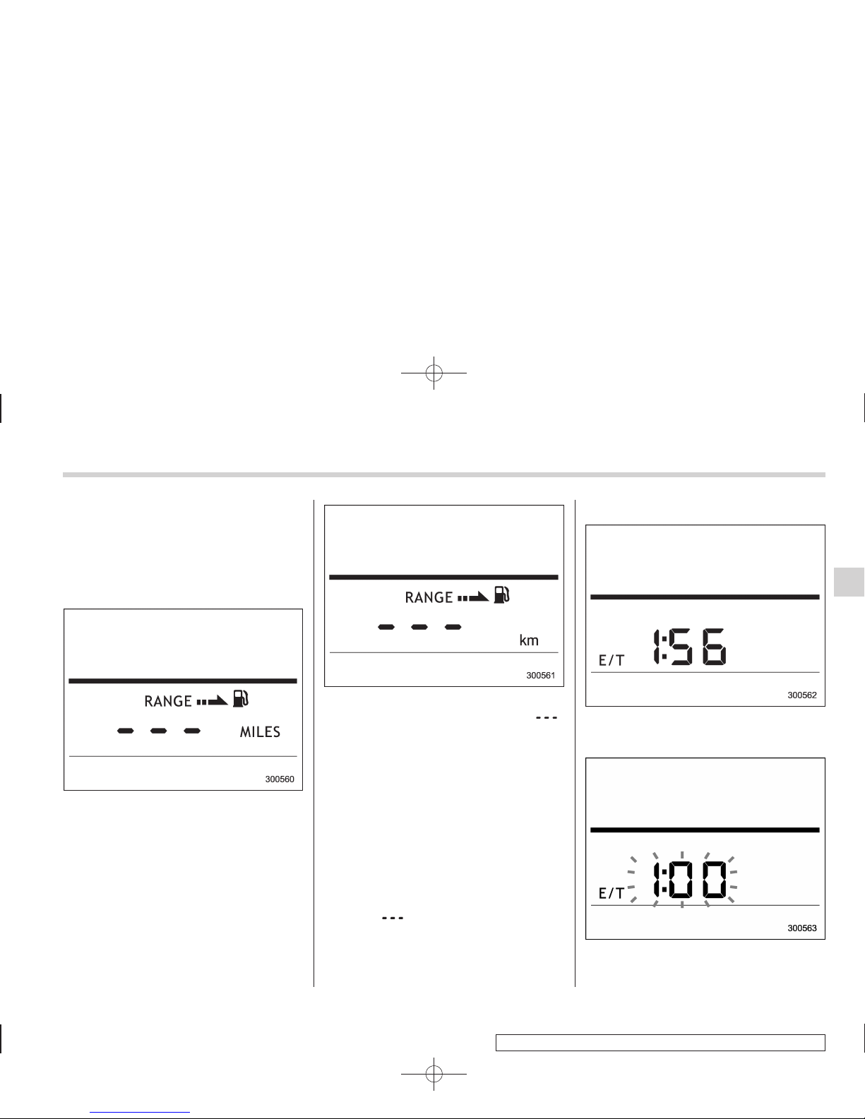
The driving range indicates the distance
that can be driven taking into account the
Page 25
Black plate (155,1)
北米Model "A3160BE-C" EDITED: 2010/ 11/ 19
amount of fuel remaining in the tank and
the average rate of fuel consumption.
When the low fuel warning light illuminates, the driving range indication flashes
for 5 seconds. (The display first switches
to the driving range indication if it was
originally giving some other indication.)
U.S.-spec. models
Except U.S.-spec. models
If the driving range is shown as “ ”,
there is only a tiny amount of fuel left in the
tank. You must refuel the vehicle immediately.
NOTE
. The driving range on remaining fuel
is only a guide. The indicated value
may differ from the actual driving range
on remaining fuel, so you must immediately fill the tank when the low fuel
warning light illuminates.
. When the low fuel warning light
illuminates, the display automatically
shows “
” even if the currently
selected indication is not for the driving range on remaining fuel.
& Journey time
The journey time shows the time that has
elapsed since the ignition switch was
turned to the “START” position.
The journey time indication flashes each
time a complete hour has elapsed. If the
Instruments and controls 3-25
– CONTINUED –
Page 26
Black plate (156,1)
北米Model "A3160BE-C" EDITED: 2010/ 11/ 19
3-26 Instruments and controls
display is giving an indication other than
the journey time, the display switches to
the journey time, flashes for 5 seconds,
and returns to its original indication each
time a complete hour has elapsed.
NOTE
The journey time is reset when the
ignition switch is turned to the “LOCK”
position. It is also reset if the ignition
switch is turned to the “LO CK” or
“Acc” position prior to restarting of
the engine.
Light control switch
WARNING
To prevent battery discharge resulting from accidentally leaving your
lights on when your vehicle is
parked, the light switch operates
only when the ignition switch is in
the “ON” position. In any other
position, the vehicle’s lights will be
out.
If you park your vehicle on a roadside at night, use the hazard warning flasher to alert the other drivers.
The light switch operates only when the
ignition switch is in the “ON” position.
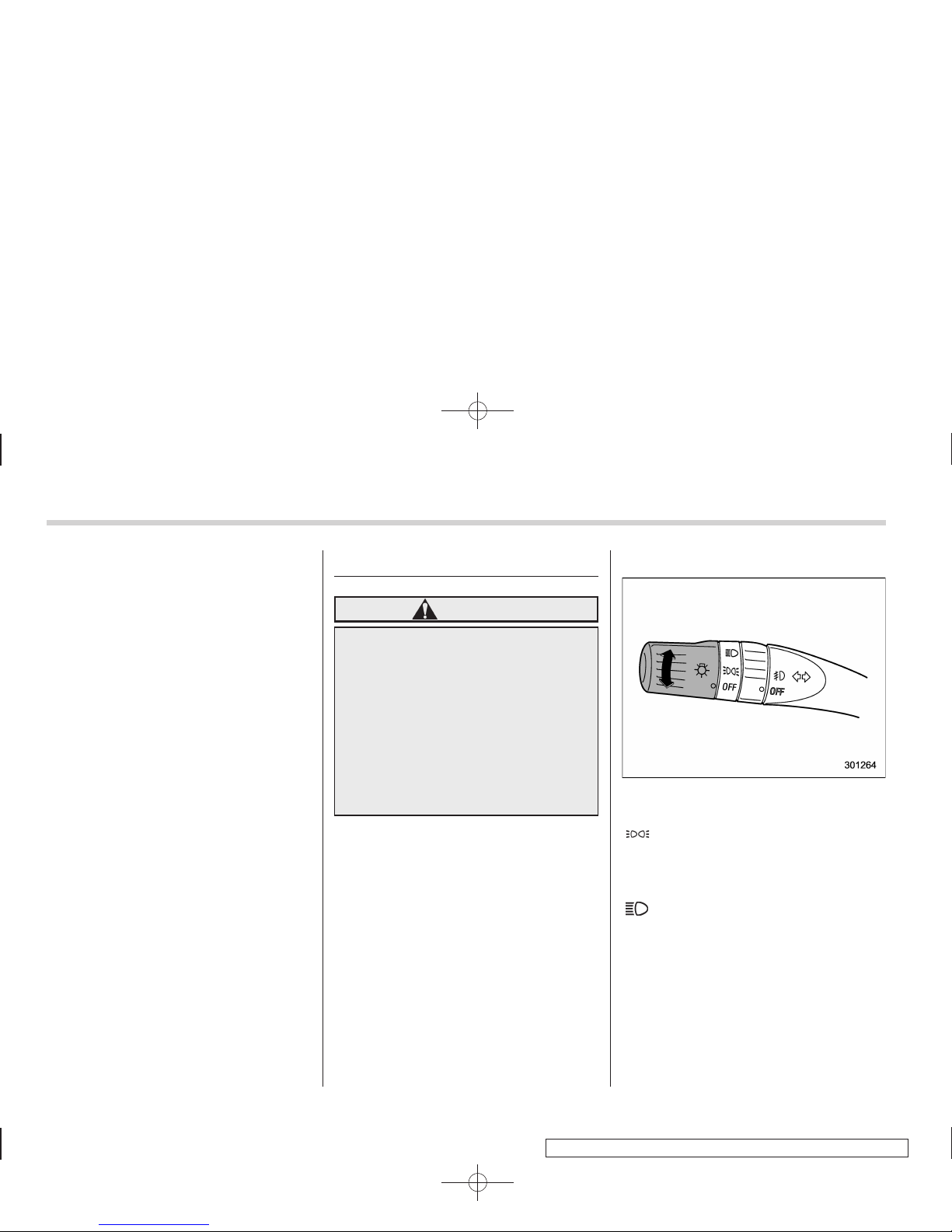
& Headlights
To turn on the headlights, turn the knob on
the end of the turn signal lever.
first position
Parking lights, instrument panel illumination, tail lights and license plate light are
on.
second position
Headlights, parking lights, instrument panel illumination, tail lights, and license
plate light are on.
Page 27
Black plate (157,1)
北米Model "A3160BE-C" EDITED: 2010/ 11/ 19
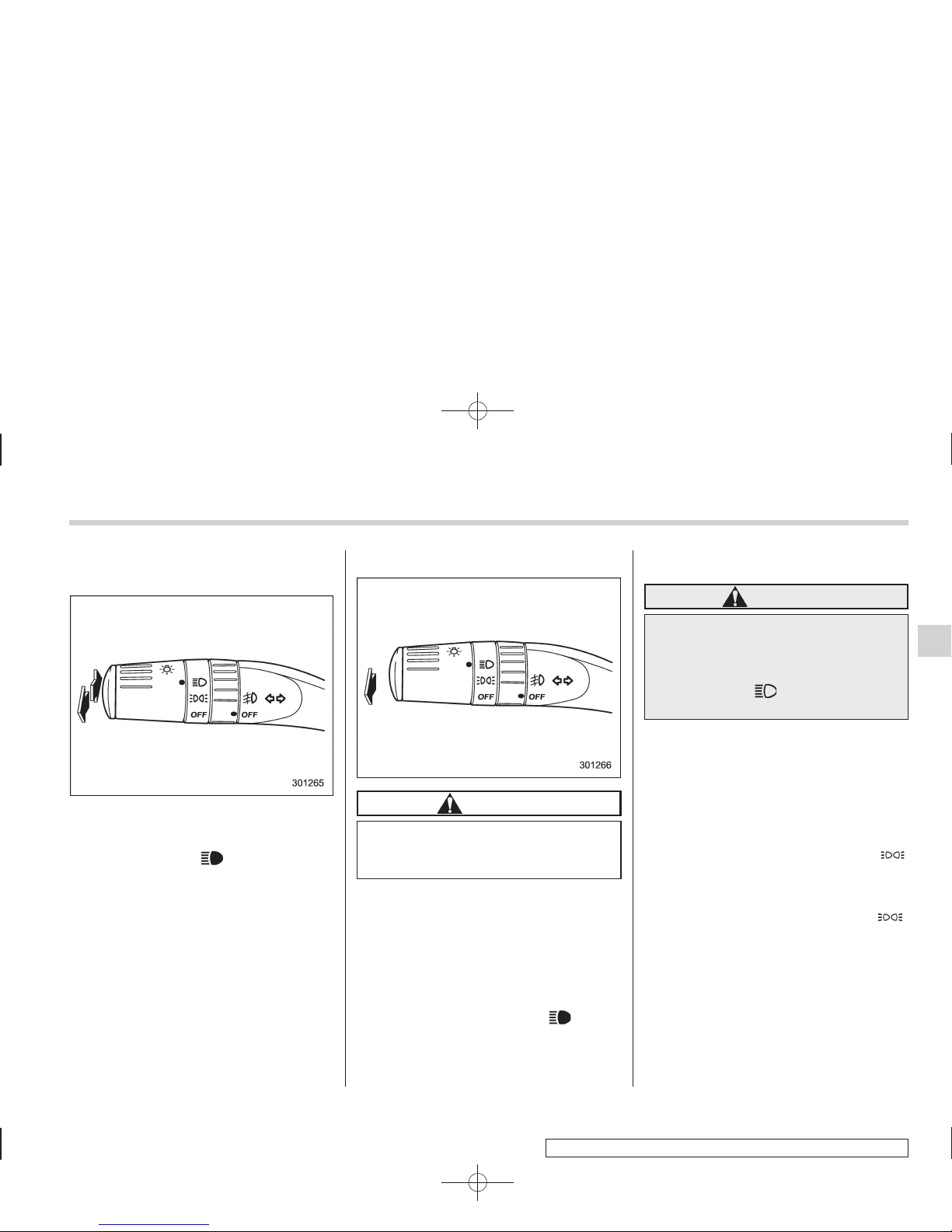
& High/low beam change (dim-
mer)
To change from low beam to high beam,
push the turn signal lever forward. When
the headlights are on high beam, the high
beam indicator light “
” on the combina-
tion meter also illuminates.
To switch back to low beam, pull the lever
back to the detent position.
& Headlight flasher
CAUTION
Do not hold the lever in the flashing
position for more than just a few
seconds.
To flash the headlights, pull the lever
toward you and then release it. The high
beam will remain on for as long as you
hold the lever. The headlight flasher works
even though the light switch is in the
“OFF” position.
When the headlights are on high beam,
the high beam indicator light “
” on the
combination meter also illuminates.
& Daytime running light system
WARNING
The brightness of the illumination of
the high beam headlights is reduced
by the daytime running light system.
The light switch must always be
turned to the “
” position when it
is dark outside.
The high beam headlights will automatically illuminate at reduced brightness
when the engine has started, under the
following conditions.
. The select lever is in a position other
than the “P” position.
. The parking brake is fully released.
. The light switch is in the “OFF” or “
”
position.
NOTE
When the light switch is in the “ ”
position, the front side marker lights,
parking lights and license plate lights
are also illuminated.
Instruments and controls 3-27
Page 28
Black plate (158,1)
北米Model "A3160BE-C" EDITED: 2010/ 11/ 19
3-28 Instruments and controls
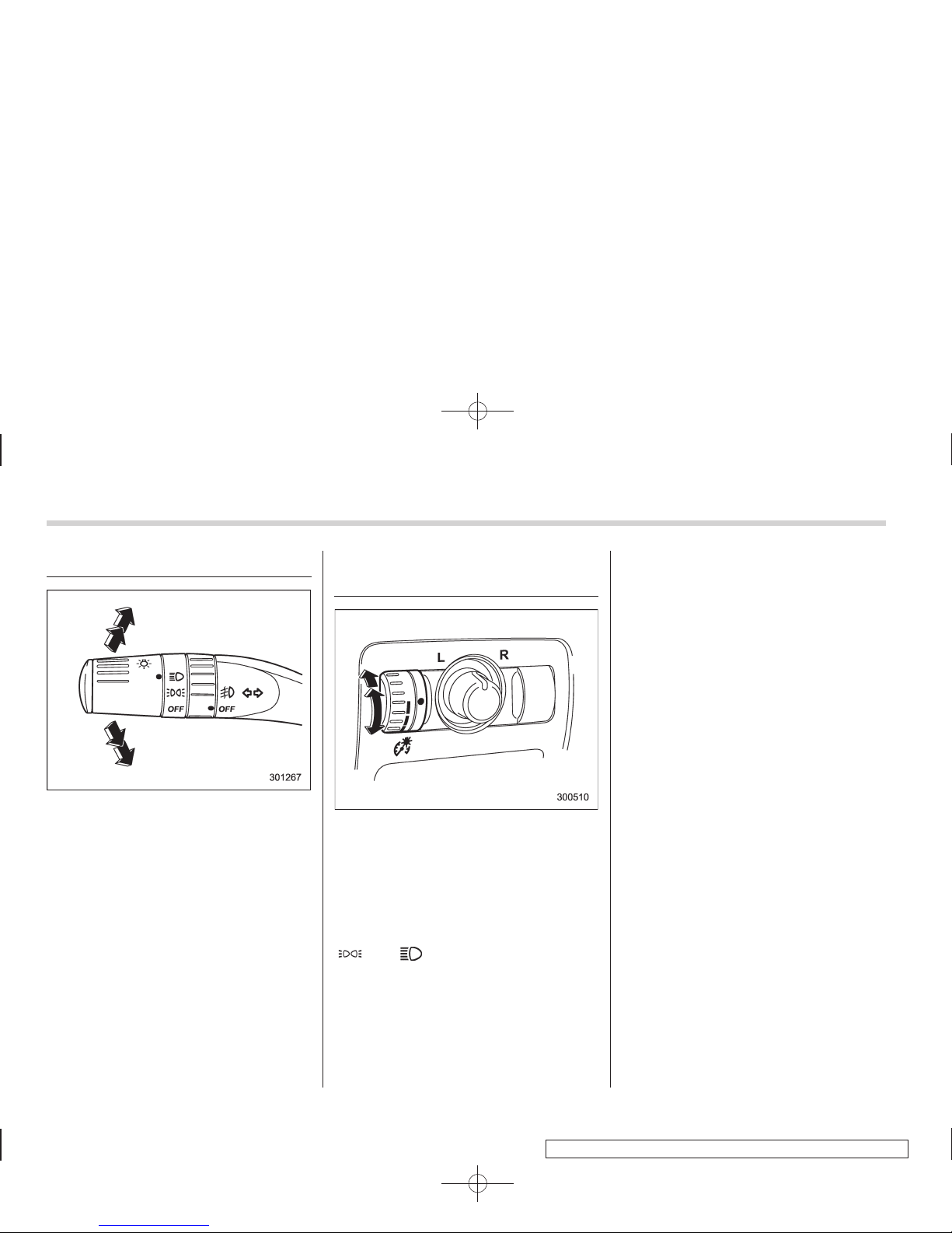
Turn signal lever
To activate the right turn signal, push the
turn signal lever up. To activate the left
turn signal, push the turn signal lever
down. When the turn is finished, the lever
will return automatically. If the lever does
not return after cornering, return the lever
to the neutral position by hand.
To signal a lane change, push the turn
signal lever up or down slightly and hold it
during the lane change. The turn signal
indicator lights will flash in the direction of
the turn or lane change. The lever will
return automatically to the neutral position
when you release it.
Illumination brightness control
When the light switch is in the “OFF”
position, you can adjust the brightness of
the instrument panel illumination for better
visibility.
The brightness of audio, air conditioner,
multi-function display (if equipped) and
instrument panel illumination automatically dims when the light switch is in the
“
” or “ ” position. You can adjust
brightness of the illumination for better
visibility.
To brighten, turn the control dial upward.
To darken, turn the control dial downward.
NOTE
When the control dial is turned fully
upward, the illumination brightness
becomes the maximum and the automatic dimming function does not work
at all.
Page 29
Black plate (159,1)
北米Model "A3160BE-C" EDITED: 2010/ 11/ 19
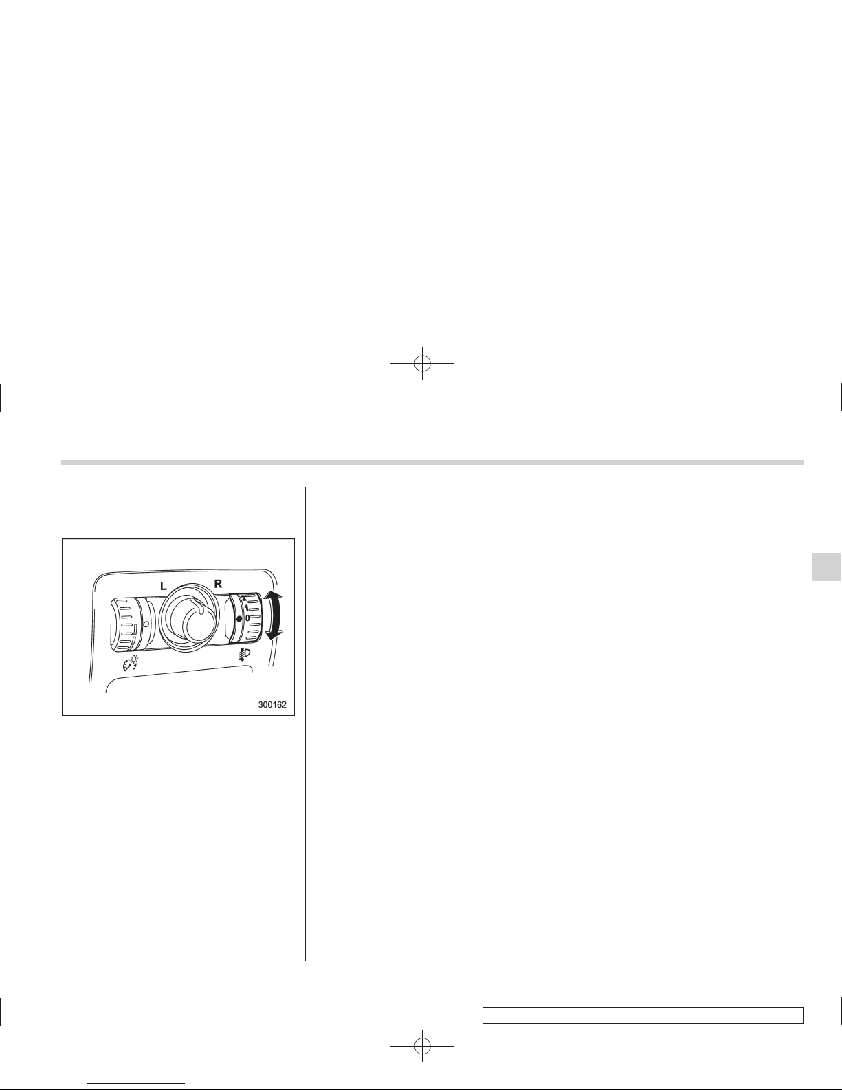
Headlight beam leveler (if
equipped)
Adjust the headlight beam level with the
following dial positions according to the
number of passengers and load condition.
Instruments and controls 3-29
– CONTINUED –
Page 30
Black plate (160,1)
北米Model "A3160BE-C" EDITED: 2010/ 11/ 19
3-30 Instruments and controls
Dial position Number of front seat
occupants
Number of 2nd seat
occupants
Number of 3rd seat
occupants
Load in the luggage
compartment area
Trailer towing
0 1 or 2 0 0 No load No
1
2 0 2 No load No
2
2 3 2 No load No
3
2 3 2 Full load No
2 3 2 Full load Yes
4
1 0 0 Full load No
1 0 0 Full load Yes
5
Not applicable Not applicable Not applicable Not applicable Not applicable
Page 31
Black plate (161,1)
北米Model "A3160BE-C" EDITED: 2010/ 11/ 19
Parking light switch
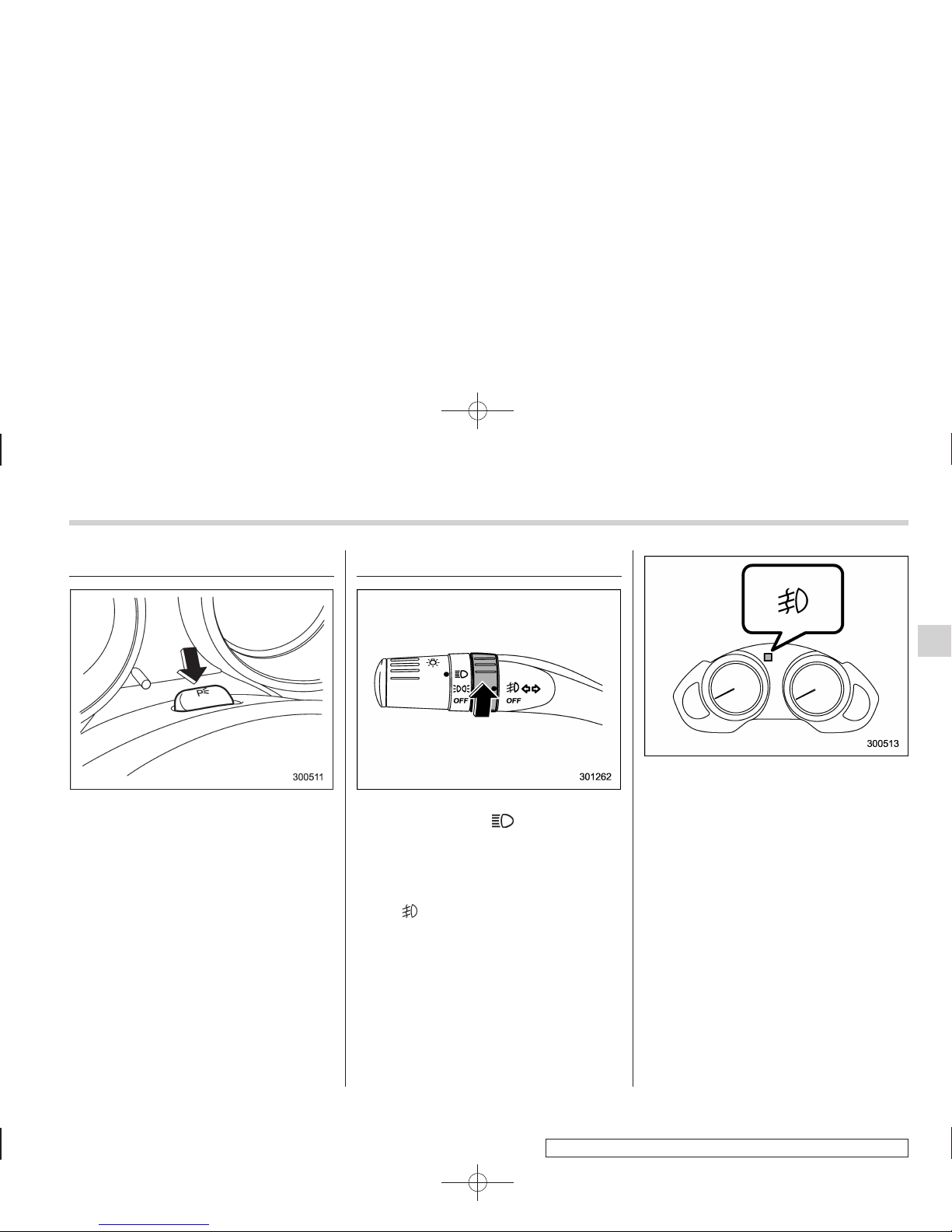
The parking light switch operates regardless of the ignition switch position.
By pushing the front end of this switch,
following lights will illuminate.
– Parking lights
– Front and rear side marker lights
– Tail lights
– License plate lights
To turn off, push the rear end of the
parking light switch.
Avoid leaving these lights on for a long
time because that will run down the
battery.
Front fog light switch
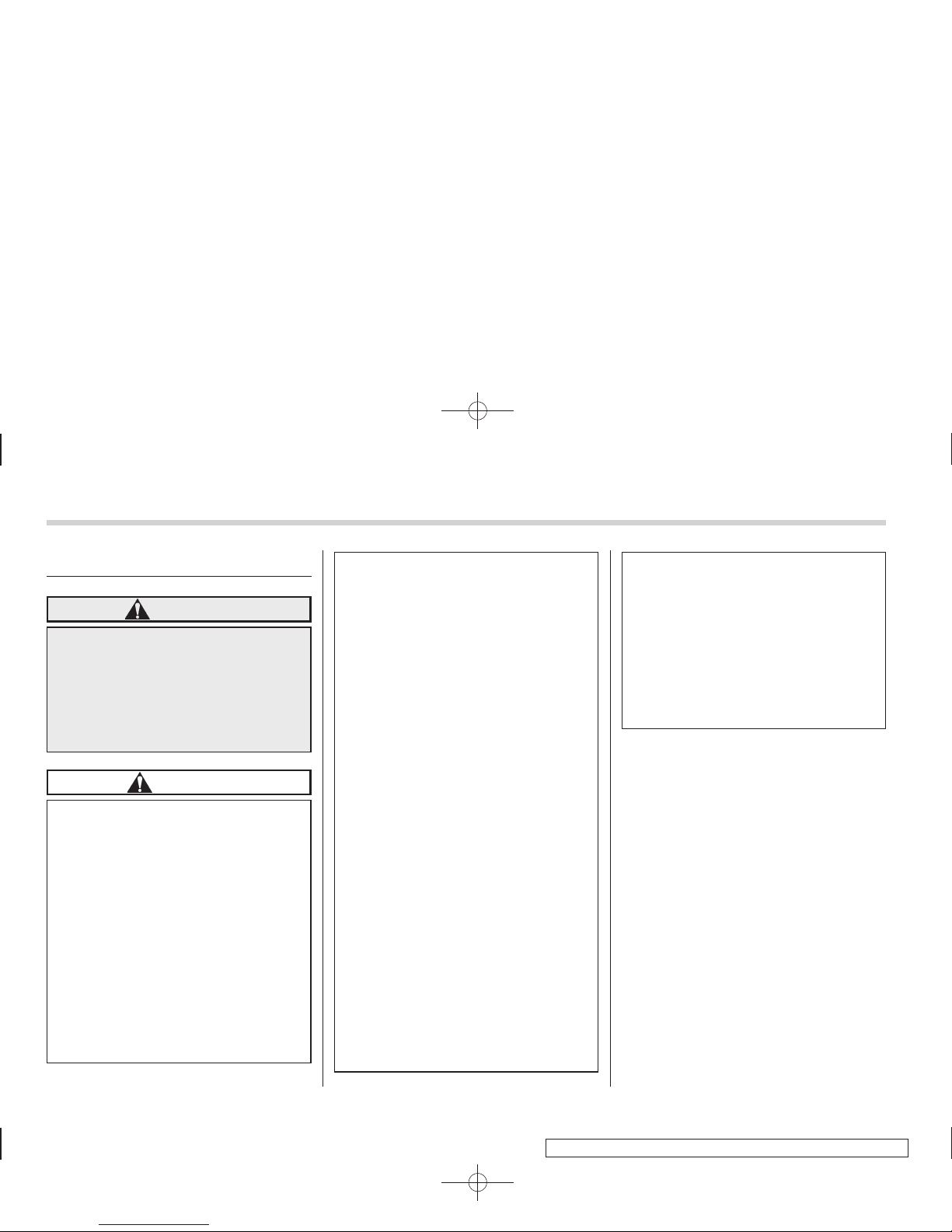
The front fog lights operate only when the
light switch is in the “
” position.
However, the front fog lights turn off when
the headlights are switched to high beam.
To turn on the front fog lights, turn the fog
light switch on the turn signal lever upward
to the “
” position.
To turn off the front fog lights, turn the
switch back down to the “OFF” position.
The indicator light on the combination
meter will illuminate when the fog lights
are illuminated.
Instruments and controls 3-31
Page 32
Black plate (162,1)
北米Model "A3160BE-C" EDITED: 2010/ 11/ 19
3-32 Instruments and controls
Wiper and washer
WARNING
In freezing weather, do not use the
windshield washer until the windshield is sufficiently warmed by the
defroster.
Otherwise the washer fluid can
freeze on the windshield, blocking
your view.
CAUTION
. Do not operate the washer con-
tinuously for more than 10 seconds, or when the washer fluid
tank is empty. This may cause
overheating of the washer motor.
Check the washer fluid level
frequently, such as at fuel stops.
. Do not operate the wipers when
the windshield or rear window is
dry. This may scratch the glass,
damage the wiper blades and
cause the wiper motor to burn
out. Before operating the wiper
on a dry windshield or rear
window, always use the windshield washer.
. In freezing weather, be sure that
the wiper blades are not frozen to
the windshield or rear window
before switching on the wipers.
Attempting to operate the wiper
with the blades frozen to the
window glass could cause not
only the wiper blades to be
damaged but also the wiper motor to burn out. If the wiper
blades are frozen to the window
glass, be sure to operate the
defroster, wiper deicer (if
equipped) or rear window defogger before turning on the wiper.
. If the wipers stop during opera-
tion because of ice or some other
obstruction on the window, the
wiper motor could burn out even
if the wiper switch is turned off. If
this occurs, promptly stop the
vehicle in a safe place, turn the
ignition switch to the “LOCK”
position and clean the window
glass to allow proper wiper operation.
. Use clean water if windshield
washer fluid is unavailable. In
areas where water freezes in
winter, use SUBARU Windshield
Washer Fluid or the equivalent.
Refer to “Windshield washer
fluid” F11-29.
Also, when driving the vehicle
when there are freezing temperatures, use non-freezing type wiper blades.
. Do not clean the wiper blades
with gasoline or a solvent, such
as paint thinner or benzine. This
will cause deterioration of the
wiper blades.
NOTE
. The front wiper motor is protected
against overloads by a circuit breaker.
The motor operates continuously under an unusually heavy load, the circuit
breaker may trip to stop the motor
temporarily. If this happens, park your
vehicle in a safe place, turn off the
wiper switch, and wait for approximately 10 minutes. The circuit breaker
will reset itself, and the wipers will
again operate normally.
. Clean your wiper blades and window glass periodically with a washer
solution to prevent streaking, and to
remove accumulations of road salt or
road film. Keep the washer button
depressed at least for 1 second so that
washer solution will be sprinkled all
over the windshield or rear window.
Page 33
Black plate (163,1)
北米Model "A3160BE-C" EDITED: 2010/ 11/ 19
. Grease, wax, insects or other material on the windshield or the wiper
blades results in jerky wiper operation
and streaking on the glass. If you
cannot remove those streaks after
operating the washer or if the wiper
operation is jerky, clean the outer surface of the windshield or rear window
and the wiper blades using a sponge or
soft cloth with a neutral detergent or
mild abrasive cleaner. After cleaning,
rinse the window glass and wiper
blades with clean water. The glass is
clean if no beads form on the glass
when you rinse with water.
. If you cannot eliminate the streaking
even after following this procedure,
replace the wiper blades with new
ones. For replacement instructions,
refer to “Replacement of wiper blades”
F11-30.
& Windshield wiper and washer
switches
The wiper operates only when the ignition
switch is in the “ON” or “Acc” position.
! Windshield wipers
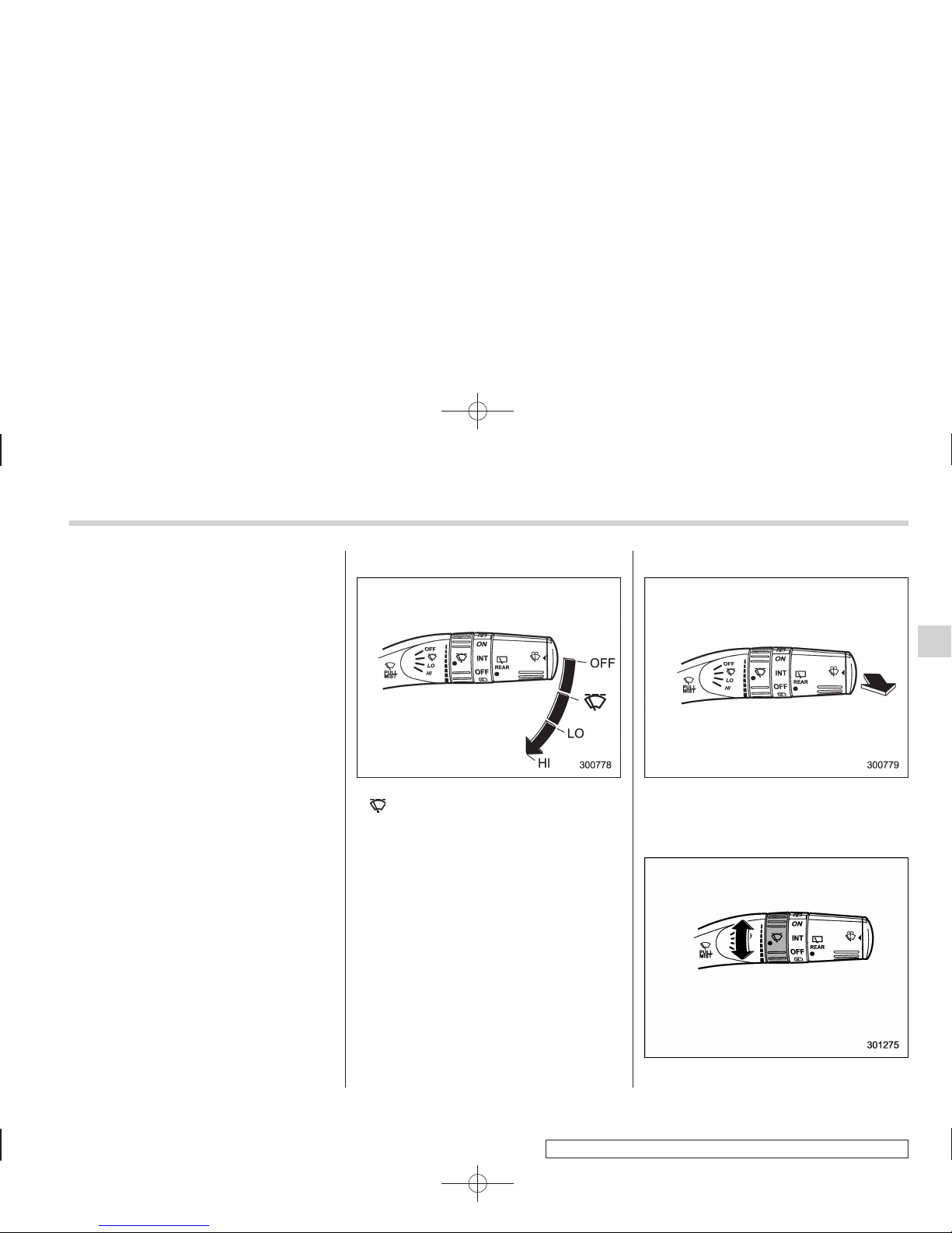
OFF: Off
: Intermittent
LO: Low speed
HI: High speed
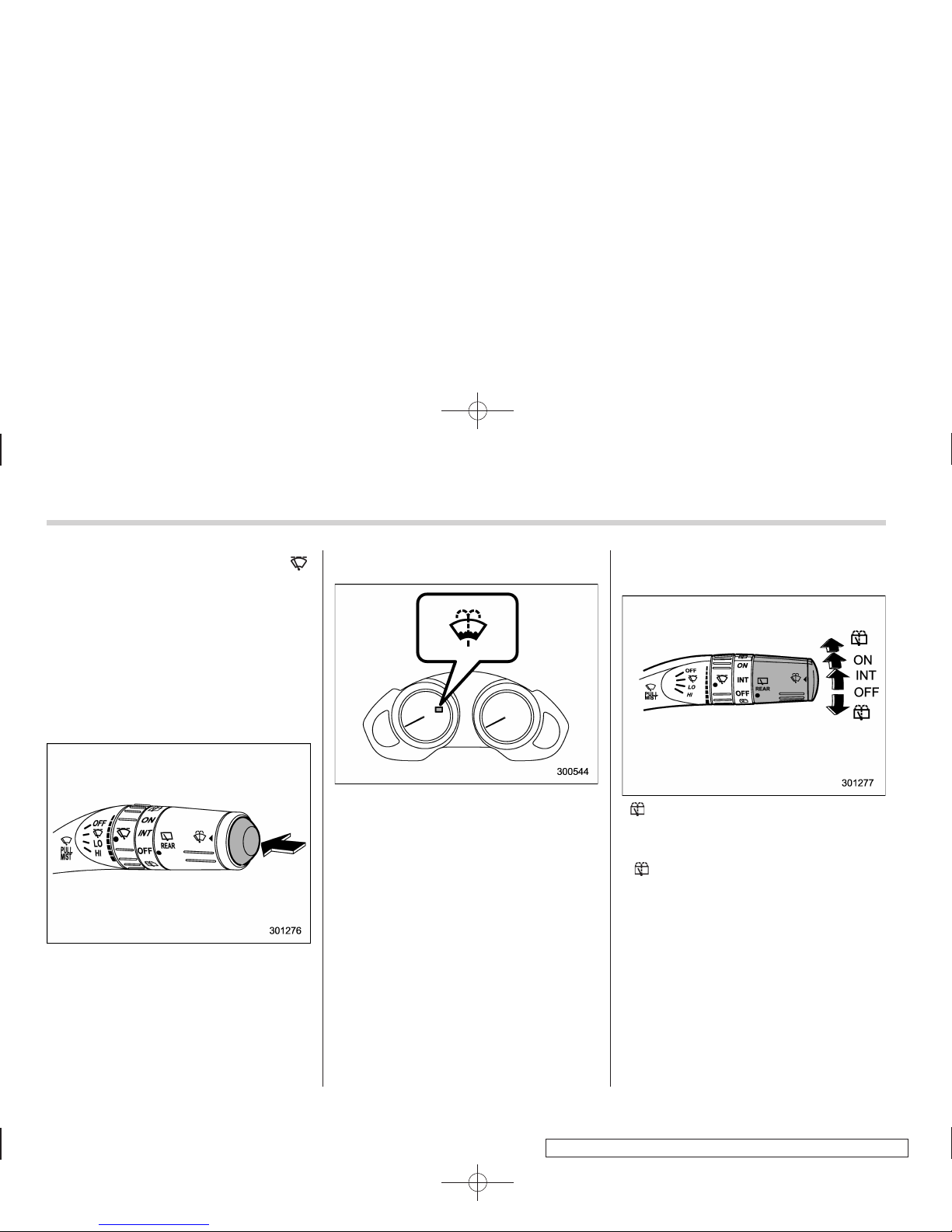
To turn the wipers on, push the wiper
control lever down.
To turn the wipers off, return the lever to
the “OFF” position.
! Mist (for a single wipe)
For a single wipe of the wipers, pull the
lever toward you. The wipers operate until
you release the lever.
! Wiper intermittent time control
Instruments and controls 3-33
– CONTINUED –
Page 34
Black plate (164,1)
北米Model "A3160BE-C" EDITED: 2010/ 11/ 19
3-34 Instruments and controls
When the wiper switch is in the “ ”
position, turn the dial to adjust the operating interval of the wiper.
The operating interval can be adjusted in
nine steps.
The intermittent operation interval varies
depending on the vehicle speed in any of
the adjustment steps (longer when the
vehicle speed is low; shorter when the
vehicle speed is high).
! Washer
To wash the windshield, push the washer
button at the end of the wiper control lever.
The washer fluid sprays until you release
the washer button. The wipers operate
while you push the button.
NOTE
The windshield washer fluid warning
light illuminates when the washer fluid
level in the tank has dropped to the
lower limit. If the warning light illuminates, refill the tank with fluid. For the
tank refilling method, refer to “Windshield washer fluid” F11-29.
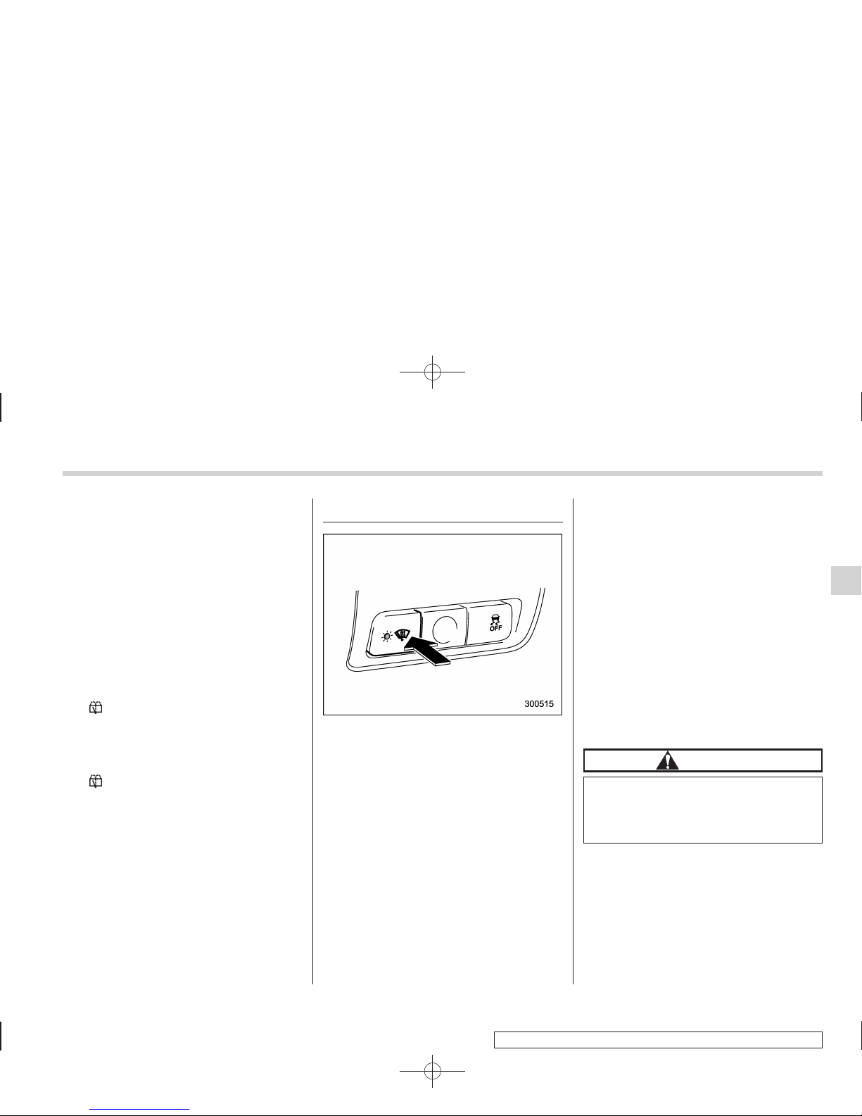
& Rear window wiper and
washer switch
: Washer (accompanied by wiper operation)
ON: Continuous
INT: Intermittent
OFF: Off
: Washer
! Rear wiper
To turn the rear wiper on, turn the knob on
the end of the wiper control lever upward
to the “INT” or “ON” position.
To turn the wiper off, return the knob on
the end of the lever to the “OFF” position.
With the switch turned to the “INT”
position, the rear wiper will operate intermittently at intervals corresponding to the
vehicle speed (longer when the vehicle
Page 35
Black plate (165,1)
北米Model "A3160BE-C" EDITED: 2010/ 11/ 19
speed is low; shorter when the vehicle
speed is high).
When you subsequently move the select
lever of the automatic transmission to the
“R” position, the rear wiper will switch to
continuous operation. When you move the
select lever from the “R” position to some
other position, the rear wiper will return to
intermittent operation.
! Washer
To wash the rear window while the rear
wiper is operating, turn the knob on the
end of the wiper control lever upward to
the “
” position. The washer fluid sprays
until you release the knob.
To wash the rear window when the rear
wiper is not in use, turn the knob on the
end of the wiper control lever downward to
the “
” position. The washer fluid sprays
and the wiper operates until you release
the knob.
Windshield wiper deicer
The windshield wiper deicer operates only
when the ignition switch is in the “ON”
position.
To turn on the windshield wiper deicer,
push the control switch. The indicator light
located on the switch illuminates while the
windshield wiper deicer is operating.
To turn it off, push the control switch again.
It also turns off when the ignition switch is
turned to the “Acc” or “LOCK” position.
The windshield wiper deicer will automatically shut off a fter approximately 15
minutes. If the windshield wiper blades
have been deiced completely before that
time, push the control switch to turn it off. If
deicing is not complete, you have to push
the control switch to turn it on again.
Your SUBARU dealer can set your windshield wiper deicer to the continuous
operation mode. Contact your SUBARU
dealer for details.
Once the windshield wiper deicer has
been set to the continuous operation
mode, it should be in the continuous
operation mode at any time when the
control switch is pushed to the “ON”
position.
If the battery voltage drops below the
permissible level, continuous operation of
the windshield wiper deicer is canceled
and the system stops operating.
CAUTION
To prevent the battery from being
discharged, do not operate the
windshield wiper deicer continuously for any longer than necessary.
NOTE
. Turn on the windshield wiper deicer
if the wipers are frozen to the windshield.
. If the windshield is covered with
snow, remove the snow so that the
windshield wiper deicer works effec-
Instruments and controls 3-35
– CONTINUED –
Page 36
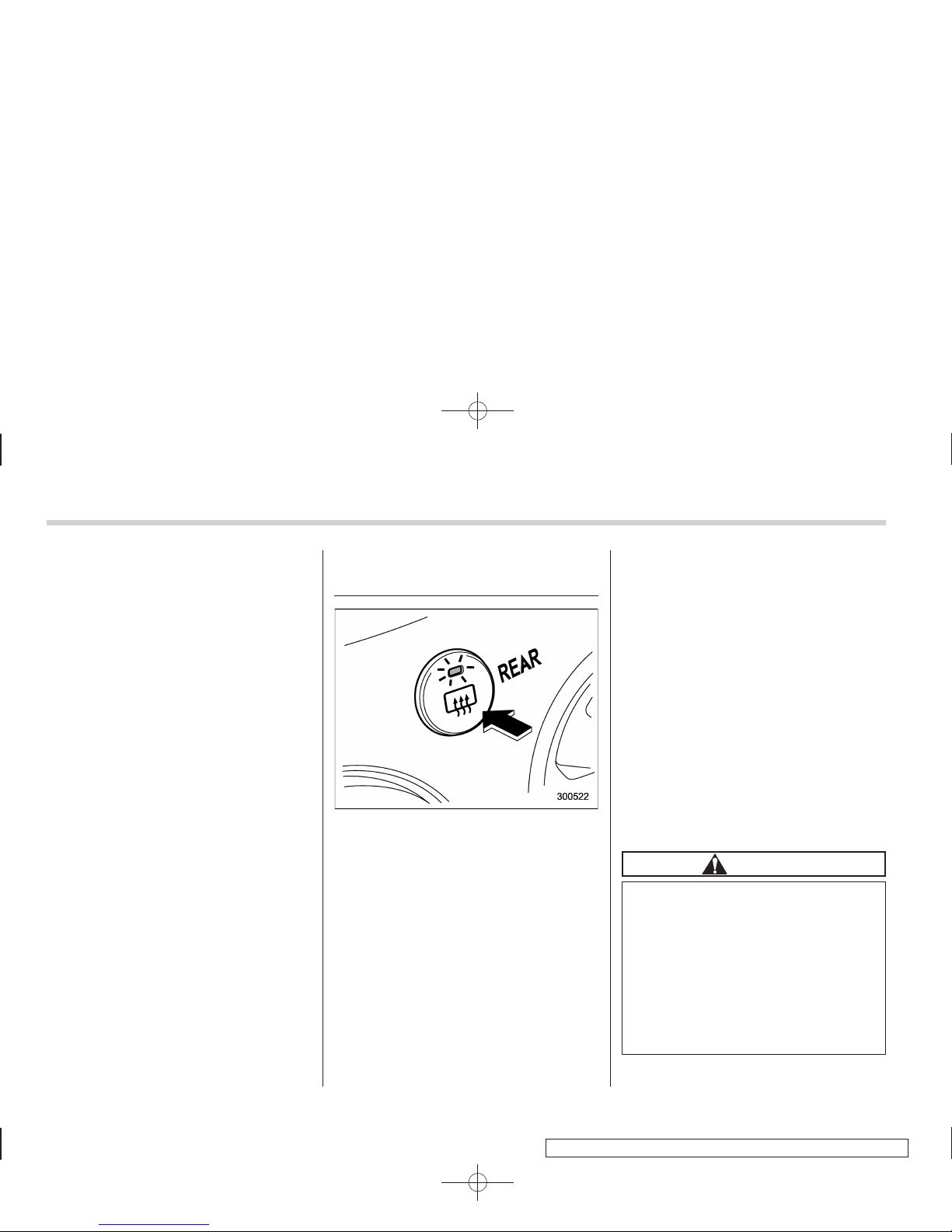
Black plate (166,1)
北米Model "A3160BE-C" EDITED: 2010/ 11/ 19
3-36 Instruments and controls
tively.
. While the windshield wiper deicer is
in the continuous operation mode, if
the vehicle speed remains at 9 mph (15
km/h) or less for 15 minutes, the windshield wiper deicer automatically stops
operating.
Rear window defogger button
The rear window defogger operates only
when the ignition switch is in the “ON”
position.
To turn on the defogger, push the control
switch that is located on the climate
control panel. The indicator light located
on the control switch illuminates while the
rear window defogger is operating.
To turn it off, push the control switch again.
It also turns off when the ignition switch is
turned to the “Acc” or “LOCK” position.
The defogger will automatically shut off
after approximately 15 minutes. If the rear
window has been cleared completely
before that time, push the control switch
to turn it off. If defrosting or defogging is
not complete, you have to push the control
switch to turn it on again.
Your SUBARU dealer can set your rear
window defogger to the continuous operation mode. Contact your SUBARU dealer
for details.
Once the rear window defogger has been
set to the continuous operation mode, it
should be in the continuous operation
mode at any time when the control switch
is pushed to the “ON” position.
If the battery voltage drops below the
permissible level, continuous operation of
the rear window defogger is canceled and
the system stops operating.
CAUTION
. Do not use sharp instruments or
window cleaner containing abrasives to clean the inner surface
of the rear window. They may
damage the conductors printed
on the window.
. To prevent the battery from being
discharged, do not operate the
defogger continuously for any
longer than necessary.
Page 37
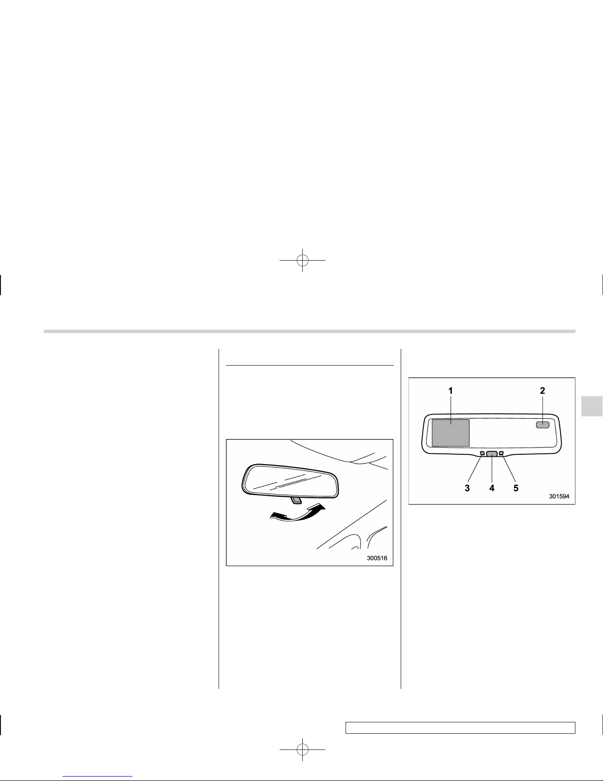
Black plate (167,1)
北米Model "A3160BE-C" EDITED: 2010/ 11/ 19
NOTE
The outside mirror defogger also operates while the rear window defogger is
operating.
Mirrors
Always check that the inside and outside
mirrors are properly adjusted before you
start driving.
& Type A inside mirror (if
equipped)
The mirror has a day and night position.
Pull the tab at the bottom of the mirror
toward you for the night position. Push it
away for the day po sition . The night
position reduces glare from headlights.
& Type B inside mirror (if
equipped)
1) Rear view image display
2) Electronic compass display
3) Auto dimming indicator
4) Multifunction button
5) Photosensor
The mirror has the following features.
. Rear view image display
. Auto-dimming function for anti-glare
capability
. Electronic compass display
You can display the various functions of
these features based on how long you
press the multifunction button.
Instruments and controls 3-37
– CONTINUED –
Page 38
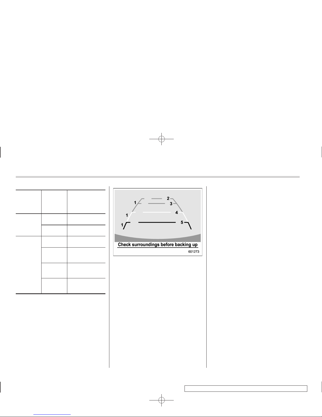
Black plate (168,1)
北米Model "A3160BE-C" EDITED: 2010/ 11/ 19
3-38 Instruments and controls
Gear
position
Period of
time multi-
function
button is
pressed
Function
displayed
R (reverse)
Briefly
Rear view display
ON/OFF*
More than
3 seconds
Help lines indication ON/OFF
Except
R (reverse)
Briefly
Auto-dimming
function ON/OFF*
3to6
seconds
Electronic compass display ON/
OFF
6to9
seconds
Enter the compass zone setting
mode
9to12
seconds
Enter the compass calibration
mode
*: The setting returns to “ON” as a default
setting every time the ignition switch is turned to
the “ON” position.
! Rear view image display
When the ignition switch is “ON” and the
select lever is set to “R”, the rear view
camera automatically displays the rear
view image behind the vehicle on the
inside mirror.
Also, the following help lines are indicated
as a guide to help you realize the actual
distance from the display.
1) Vehicle width line (oblique vertical line)
2) Approx. 10 feet (3 m) from the bumper
(green horizontal line)
3) Approx. 6.5 feet (2 m) from the bumper
(green horizontal line)
4) Approx. 3 feet (1 m) from the bumper
(yellow horizontal line)
5) Approx. 1.5 feet (0.5 m) from the bumper
(red horizontal line)
These help lines are removable. To
remove the help lines, perform the following procedure.
1. Display the rear view image on the
mirror.
2. Press the multifunction button for more
than 3 seconds to remove the help lines.
To display the help lines, press the multifunction button for more than 3 seconds.
For precautions about the rear view
camera and the rear view image, refer to
“Rear view camera” F6-21.
! Auto-dimming function
The auto-dimming function is an anti-glare
capability which automatically reduces
glare coming from headlights of vehicles
behind you.
By briefly pressing the multifunction button, the auto-dimming function is toggled
on or off. When the auto-dimming function
is on, the auto dimming indicator light
(green) will illuminate.
Even with the mirror in anti-glare mode,
the mirror surface turns bright if the
transmission is shifted into reverse. This
is to ensure good rearward visibility during
reversing.
Page 39
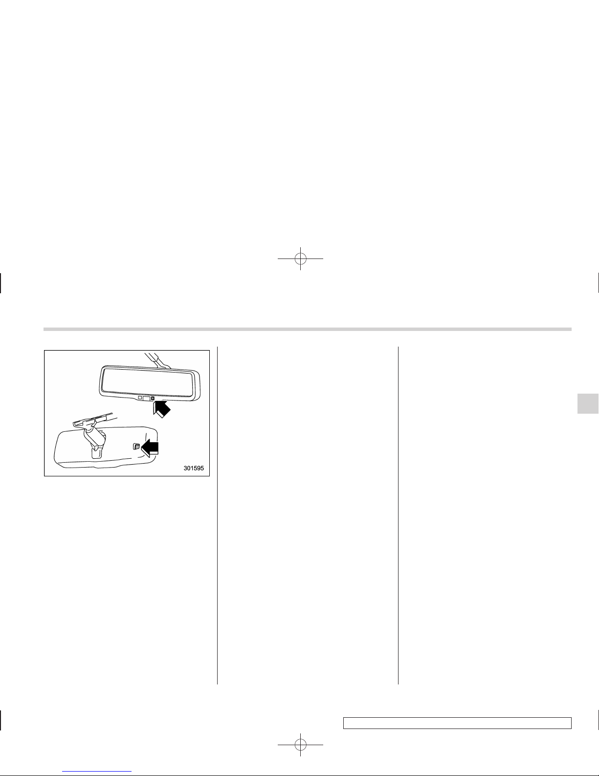
Black plate (169,1)
北米Model "A3160BE-C" EDITED: 2010/ 11/ 19
The mirror has a photosensor attached on
both the front and back sides. Use care
not to cover the sensors with stickers, or
other similar items. Periodically wipe the
sensors clean using a piece of dry soft
cotton cloth or an applicator.
NOTE
When cleaning the mirror, use a paper
towel or similar item dampened with
glass cleaner. Do not spray glass
cleaner directly on the mirror surface.
By doing so, the sprayed glass cleaner
could enter the inside of the mirror
housing. That may cause a malfunction
in the mirror.
! Electronic compass display
By pressing the multifunction button for 3
to 6 seconds, the compass display is
toggled on or off. When the compass
display is on, an illuminated compass
reading will appear on the mirror.
Using the electronic compass properly,
the following compass zone adjustment
and compass calibration will be necessary.
! Compass zone adjustment
1. The compass zone has been set to
zone “8” at the time of shipment from the
factory. Refer to the “Compass calibration
zones” map, which is attached to the end
of this manual to verify that the compass
zone setting is correct for your geographical location.
2. Press and hold the multifunction button for 6 to 9 seconds, and then release it.
The zone number will be displayed.
3. Press the multifunction button repeatedly to cycle the display through all
possible zone settings. Stop cycling when
the correct zone number for your location
is displayed.
4. Releasing the button for 3 seconds will
exit the zone setting mode.
! Compass calibration
1. For optimum calibration, switch off all
nonessential electrical accessories (rear
window defogger, heater/air conditioning
system, spotlight, etc.) and ensure all
doors are shut.
2. Drive to an open, level area away from
large metallic objects or structures and
make certain the ignition switch is in the
“ON” position.
3. Press and hold the multifunction button for 9 to 12 seconds, and then release
it. The compass will enter the calibration
mode, then “C” and the direction will be
displayed.
4. Drive slowly in a circle until “C”
disappears from the display. Driving in
two or three circles might be necessary.
The compass is now calibrated.
5. Further calibration may be necessary
should outside influences cause the compass to read inaccurately. You will notice
any outside influence if the compass tends
to read in only one particular direction.
Should you encounter this situation, return
to step 1 of the above procedure and
recalibrate the compass.
Instruments and controls 3-39
– CONTINUED –
Page 40
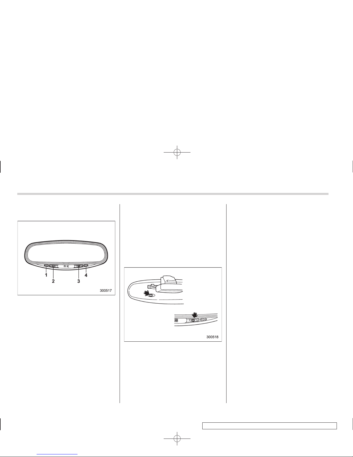
Black plate (170,1)
北米Model "A3160BE-C" EDITED: 2010/ 11/ 19
3-40 Instruments and controls
& Type C inside mirror (if
equipped)
1) Left button
2) Auto dimming indicator
3) Photosensor
4) Right button
This mirror has an anti-glare feature which
automatically reduces glare coming from
headlights of vehicles behind you. It also
contains a built-in compass.
. By pressing and releasing the left
button, the automatic dimming function is
toggled on or off. When the automatic
dimming function is on, the auto dimming
indicator light (green) located to the right
of the button will illuminate.
. By pressing and releasing the right
button, the compass display is toggled on
or off. When the comp ass is on, an
illuminated compass reading will appear
in the lower part of the mirror.
Even with the mirror in anti-glare mode,
the mirror surface turns bright if the
transmission is shifted into reverse. This
is to ensure good rearward visibility during
reversing.
! Photosensors
The mirror has a photosensor attached on
both the front and back sides. If the glare
from the headlights of vehicles behind you
strikes the mirror, these sensors detect it
and make the reflection surface of the
mirror dimmer to help prevent you from
being blinded. For this reason, use care
not to cover the sensors with stickers, or
other similar items. Periodically wipe the
sensors clean using a piece of dry soft
cotton cloth or an applicator.
! Compass calibration
1. For optimum calibration, switch off all
nonessential electrical accessories (rear
window defogger, heater/air conditioning
system, spotlight, etc.) and ensure all
doors are shut.
2. Drive to an open, level area away from
large metallic objects or structures and
make certain the ignition switch is in the
“ON” position.
3. Press and hold the left button for 3
seconds then release, and the compass
will enter the calibration mode. “CAL” and
direction will be displayed.
4. Drive slowly in a circle until “CAL”
disappears from the display (approximately two or three circles). The compass
is now calibrated.
5. Further calibration may be necessary
should outside influences cause the mirror
to read inaccurately. You will know that
this has occurred if your compass begins
to read in only limited directions. Should
you encounter this situation, return to step
one of the above procedure and recalibrate the mirror.
Page 41
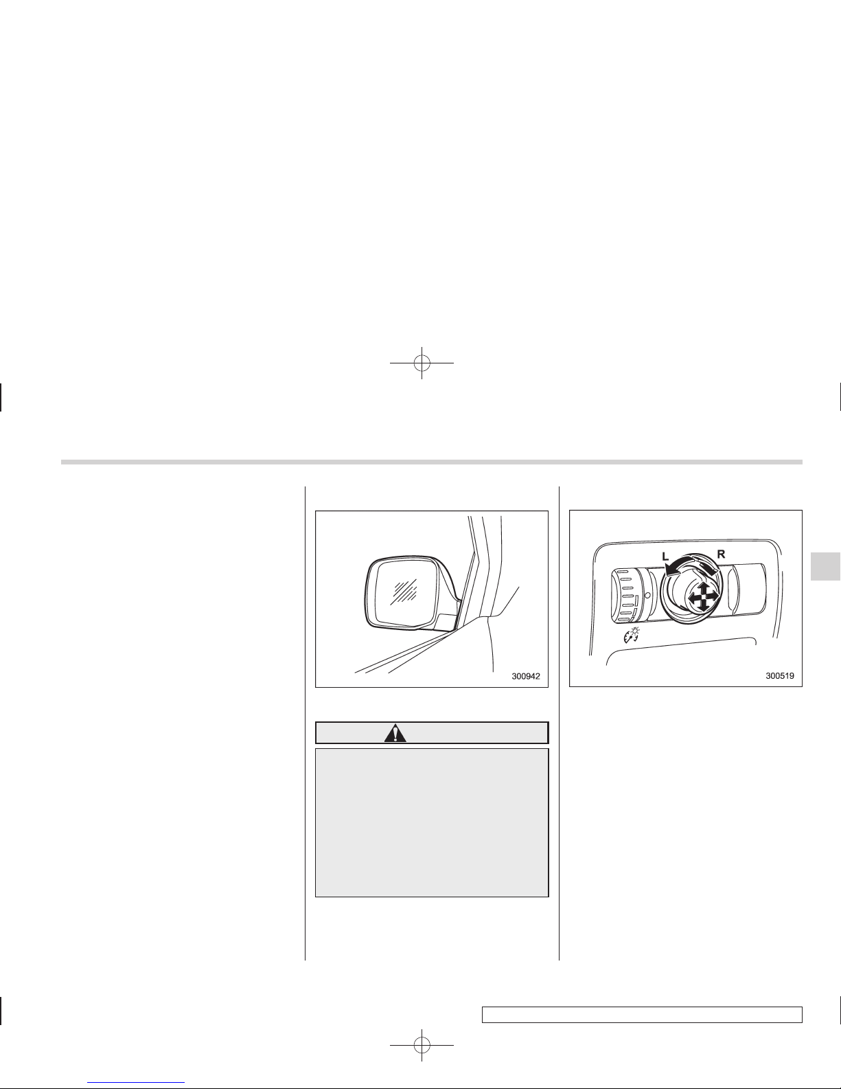
Black plate (171,1)
北米Model "A3160BE-C" EDITED: 2010/ 11/ 19
! Compass zone adjustment
1. The zone setting is factory preset to
Zone 8. Refer to the “Compass calibration
zone” map attached to the end of this
manual to verify that the compass zone
setting is correct for your geographical
location.
2. Press and hold the right button for 3
seconds then release, and the word
“ZONE” will briefly appear and then the
zone number will be displayed.
3. Press the right-hand button repeatedly
to cycle the display through all possible
zone settings. Stop cycling when the
correct zone setting for your location is
displayed.
4. Releasing the button for 3 seconds will
exit the zone setting mode.
& Outside mirrors
! Convex mirror (passenger side)
WARNING
Objects look smaller in a convex
mirror and farther away than when
viewed in a flat mirror. Do not use
the convex mirror to judge the
distance of vehicles behind you
when changing lanes. Use the inside
mirror (or glance backwards) to
determine the actual size and distance of objects that you view in
convex mirror.
! Remote control mirror switch
The remote control mirrors operate only
when the ignition switch is in the “ON” or
“Acc” position.
1. Turn the knob to the “L” side to adjust
the left-hand mirror or to the “R” side to
adjust the right-hand mirror.
2. Move the knob in the direction you
want to move the mirror.
3. Return the knob to the neutral position
to prevent unintentional operation.
The mirrors can also be adjusted manually.
Instruments and controls 3-41
– CONTINUED –
Page 42
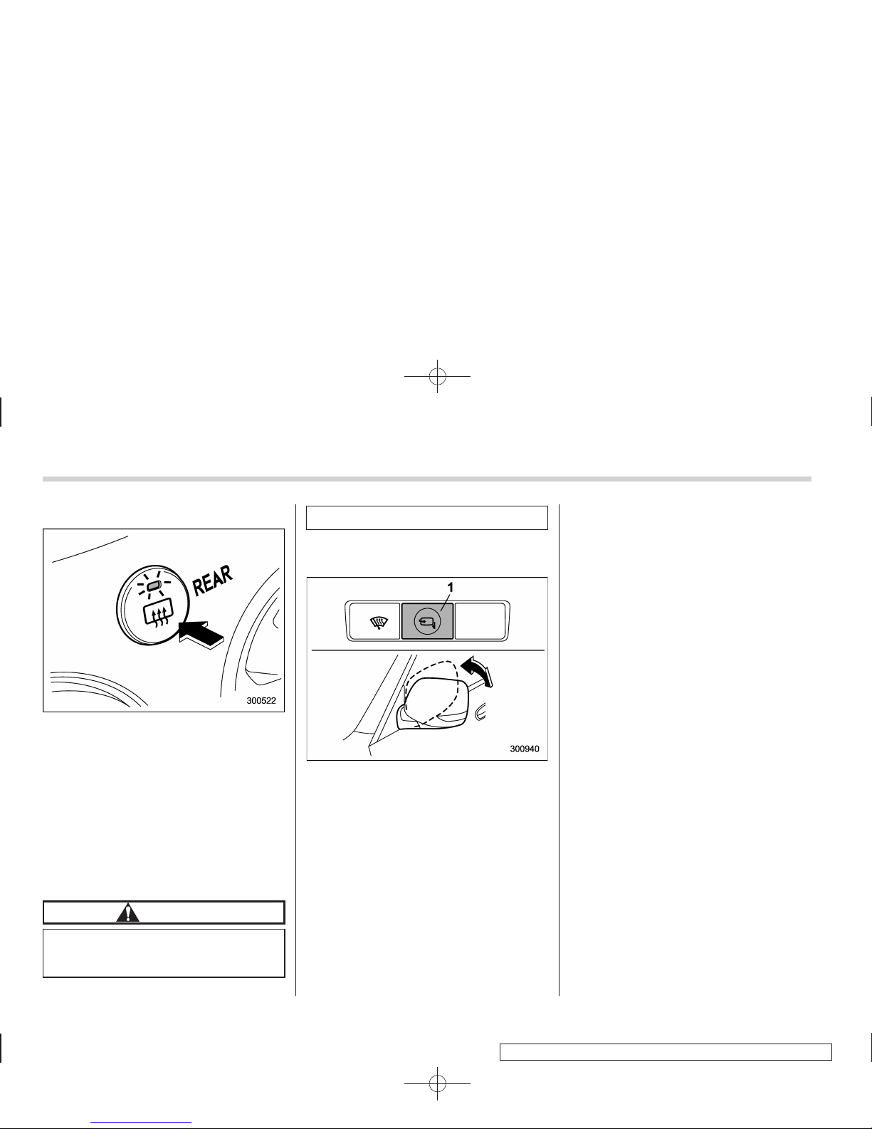
Black plate (172,1)
北米Model "A3160BE-C" EDITED: 2010/ 11/ 19
3-42 Instruments and controls
! Outside mirror defogger
The outside mirror defogger shares the
control switch with the rear window defogger. Therefore, the outside mirror defogger always operates with the rear
window defogger.
If the rear window defogger is set to the
continuous operation mode, the outside
mirror defogger also follows the continuous setting.
For details, refer to “Rear window defogger button” F3-36.
CAUTION
To prevent the battery from being
discharged, do not operate the defogger continuously for any longer
than necessary.
! Power folding mirror switch (if
equipped)
1) Power folding mirror switch
The power folding mirror switch operates
only when the ignition switch is in the “ON”
or “Acc” position.
To fold the outside mirrors, push the power
folding mirror switch. To unfold the mirrors,
push the switch again.
NOTE
. When the temperature is low, the
outside mirrors may stop during operation. Push the switch again. When the
outside mirrors do not work by switch
operation, move them several times
manually. This makes it possible to
operate them by switch operation.
. When you operate the power folding
mirror switch continuously, it may
temporarily stop working. This is not
a malfunction. Operate it again after
waiting for a short period of time.
. When you unfold the outside mirrors
manually, the mirrors may become
unstable. Be sure to unfold the mirrors
by switch operation. If the outside
mirrors are still unstable, fold the
mirrors again manually and then unfold
them by switch operation.
Page 43
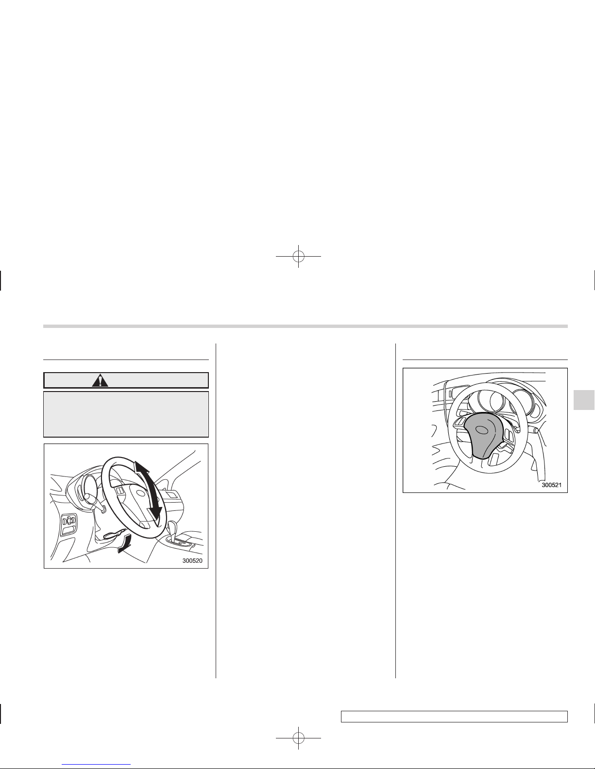
Black plate (173,1)
北米Model "A3160BE-C" EDITED: 2010/ 11/ 19
Tilt steering wheel
WARNING
Do not adjust the steering wheel tilt
position while driving. This may
cause loss of vehicle control and
result in personal injury.
1. Adjust the seat position. Refer to
“Front seats” F1-2.
2. Pull the tilt lock lever down.
3. Move the steering wheel to the desired
level.
4. Pull the lever up to lock the steering
wheel in place.
5. Make sure that the steering wheel is
securely locked by moving it up and down.
Horn
To sound the horn, push the horn pad.
Instruments and controls 3-43
Page 44

Black plate (2,1)
Model "ALL_MODEL_MEMO" EDITED: 2007/ 6/ 22
Left Page
————————————————————————————————————————
————————————————————————————————————————
————————————————————————————————————————
————————————————————————————————————————
————————————————————————————————————————
————————————————————————————————————————
————————————————————————————————————————
————————————————————————————————————————
————————————————————————————————————————
————————————————————————————————————————
————————————————————————————————————————
————————————————————————————————————————
————————————————————————————————————————
 Loading...