

Sua ionTig 200 AC/DC Operation Manual
ionTig 200 AC/DC
Copyright © Mundaka Welding & Gases, Inc.
ionTig 200 AC/DC
INVERTER - AC/DC PULSED TIG WELDER
OPERATION MANUAL
IMPORTANT: Read this Owner’s Manual Completely before attempting to use this
equipment. Save this manual and keep it handy for quick reference. Pay particular
attention to the safety instructions we have provided for your protection. Contact your
distributor if you do not fully understand this manual.

ionTig 200 AC/DC
Copyright © Mundaka Welding & Gases, Inc.
2
CONTENT
1. SAFETY .................................................................................................................................................... 3
1.1 Signal Explanation....................................................................................................................................... 3
1.2 The Knowledge of Electric and Magnetic Fields........................................................................................... 6
2. Overview...................................................................................................................................................7
2.1 Brief Introduction ........................................................................................................................................ 7
2.3 Volt-Ampere Characteristic........................................................................................................................ 10
3. Installation and Adjustment..................................................................................................................... 11
3.1 Parameters................................................................................................................................................ 11
3.2 Duty cycle and Over-heat........................................................................................................................... 12
3.3 Movement and Placement.......................................................................................................................... 12
3.4 Power supply input connection .................................................................................................................13
3.5 Polarity Connection (MMA)........................................................................................................................ 13
3.6 Assembling the equipment (TIG)................................................................................................................ 13
4. Operation................................................................................................................................................ 14
4.1 Layout for the panel................................................................................................................................... 14
4.2 Control panel.............................................................................................................................................15
4.3 Remote control.......................................................................................................................................... 20
4.3.1 Pedal switch control ...............................................................................................................................20
4.3.2 Remote box control................................................................................................................................. 21
4.3.3 Gun switch control current .....................................................................................................................22
4.4 Argon Arc Welding Operation.................................................................................................................... 22
4.4.1 TIG welding (4T operation) ............................................................................................................... 22
4.4.2 TIG welding (2T operation)......................................................................................................................24
4.5 Welding Parameters................................................................................................................................... 26
4.5.1 Joint forms in TIG/MMA......................................................................................................................... 26
4.5.2 The explanation of welding quality.......................................................................................................... 26
4.5.3 TIG Parameters Matching........................................................................................................................ 27
4.6 Operation Environment.............................................................................................................................. 30
4.7 Operation Notices...................................................................................................................................... 31
5. Maintenance & Troubleshooting..............................................................................................................31
5.1 Maintenance.............................................................................................................................................. 31
5.2 Troubleshooting........................................................................................................................................ 33
5.3 Electrical principle drawing:...................................................................................................................... 36
ionTig 200 AC/DC
Copyright © Mundaka Welding & Gases, Inc.
3
1. SAFETY
1.1 Signal Explanation
Welding may damage your body or others, so please take protection
measure in operation.
Only ones who are trained professionally can install, debug, operate,
maintain and repair the equipment.
Do not maintain and repair the machine when the machine is
connected with power.
THE ROTATING PARTS MAY BE DANGEROUS
Keep all equipment safety guards, covers and devices in position and
in good repair. Keep hands, hair, clothing and tools away from V-belts,
gears, fans and all other moving parts when starting, operating or
repairing equipment.
Do not put your hands near the engine fan. Do not attempt to override
the governor or idler by pushing on the throttle control rods while the
engine is running.
Use only compressed gas cylinders containing the correct shielding
gas for the process used and properly operating regulators designed
for the gas and pressure used. All hoses, fittings, etc. should be
suitable for the application and maintained in good condition.
Always keep cylinders in an upright position securely chained to an
undercarriage or fixed support.
Cylinders should be located:
o Away from areas where they may be struck or subjected to
physical damage.
o A safe distance from arc welding or cutting operations and any
other source of heat, sparks, or flame.
Never allow the electrode, electrode holder or any other electrically
“hot” parts to touch a cylinder.
Keep your head and face away from the cylinder valve outlet when
opening the cylinder valve.
Valve protection caps should always be in place and hand tight except
when the cylinder is in use or connected for use.
ionTig 200 AC/DC
Copyright © Mundaka Welding & Gases, Inc.
4
FUMES AND GASES CAN BE DANGEROUS
Welding may produce fumes and gases hazardous to health. Avoid
breathing these fumes and gases. When welding, keep your head out
of the fume. Use enough ventilation and/or exhaust at the arc to keep
fumes and gases away from the breathing zone. When welding with
electrodes which require special ventilation such as stainless or hard
facing or on lead or cadmium plated steel and other metals or coatings
which produce highly toxic fumes, keep exposure as low as possible
and below Threshold Limit Values using local exhaust or mechanical
ventilation. In confined spaces or in some circumstances, outdoors, a
respirator may be required. Additional precautions are also required
when welding on galvanized steel.
Do not weld in locations near chlorinated hydrocarbon vapors coming
from degreasing, cleaning or spraying operations. The heat and rays of
the arc can react with solvent vapors to form phosgene, a highly toxic
gas, and other irritating products.
Shielded gases used for arc welding can displace air and cause injury
or death. Always use enough ventilation, especially in confined areas,
to insure breathing air is safe.
Read and understand the manufacturer’s instructions for this
equipment and the consumables to be used, including the material
safety data sheet and follow your employer’s safety practices.
ARC RAYS CAN BURN.
Use a shield with the proper filter and cover plates to protect your eyes
from sparks and the rays of the arc when welding or observing open
arc welding.
Use suitable clothing made from durable flame-resistant material to
protect your skin and that of your helpers from the arc rays.
Protect other nearby personnel with suitable, non-flammable screening
and /or warn them not to watch the arc nor expose themselves to the
arc rays or to hot spatter or metal.
ionTig 200 AC/DC
Copyright © Mundaka Welding & Gases, Inc.
5
ELECTRIC SHOCK CAN KILL.
Never touch electrical parts.
Wear dry, hole-free gloves and clothes to insulate yourself.
Insulate yourself from work and ground using dry insulation. Make
certain the insulation is large enough to cover your full area of physical
contact with work and ground.
Take carefully when using the equipment in small place, falling-off and
wet circumstance.
Never close the machine power before installation and adjustment.
Ensure to install the equipment correctly and ground the work or metal
to be welded to a good electrical (earth) ground according the
operation manual.
The electrode and work (or ground) circuits are electrically “hot” when
the welder is on. Do not touch these “hot” parts with your bare skin or
wet clothing. Wear dry, hole-free gloves to insulate hands.
In semiautomatic or automatic wire welding, the electrode, electrode
reel, welding head, nozzle or semiautomatic welding gun are also
electrically “hot”.
Always be sure the work cable makes a good electrical connection with
the metal being welded. The connection should be as close as possible
to the area being welded.
Maintain the electrode holder, work clamp, welding cable and welding
machine in good, safe operating condition. Replace damaged
insulation.
Never dip the electrode in water for cooling.
Never simultaneously touch electrically “hot” parts of electrode holders
connected to two welders because voltage between the two can be the
total of the open circuit voltage of both welders.
When working above the floor level, use a safety belt to protect yourself
from a fall should you get a shock.
FIRE AND EXPLOSION
Remove fire hazards from the welding area. If this is not possible,
cover them to prevent the welding sparks from starting a fire.
Remember that welding sparks and hot materials from welding can
easily go through small cracks and openings to adjacent areas. Avoid
welding near hydraulic lines. Have a fire extinguisher readily available.

ionTig 200 AC/DC
Copyright © Mundaka Welding & Gases, Inc.
6
1.2 The Knowledge of Electric and Magnetic Fields
Electric current flowing through any conductor causes localized Electric and Magnetic Fields (EMF). The
discussion on the effect of EMF is ongoing all the world. Up to now, no material evidences show that
EMF may have effects on health. However, the research on damage of EMF is still ongoing. Before any
Where compressed gases are to be used at the job site, special
precautions should be used to prevent hazardous situation.
When not welding, make certain no part of the electrode circuit is
touching the work or ground. Accidental contact can cause overheating
and create a fire hazard.
Do not heat, cut or weld tanks, drums or containers until the proper
steps have been taken to insure that such procedures will not cause
flammable or toxic vapors from substances inside. They can cause an
explosion even though they have been “cleaned”.
Vent hollow castings or containers before heating, cutting or welding.
They may explode.
Sparks and spatter are thrown from the welding arc. Wear oil free
protective garments such as leather gloves, heavy shirt, cuff less
trousers, high shoes and a cap over your hair. Wear ear plugs when
welding out of position or in confined places. Always wear safety
glasses with side shields when in a welding area.
Connect the work cable to the work as close to the welding area as
practical. Work cables connected to the building framework or other
locations away from the welding area increase the possibility of the
welding current passing through lifting chains, crane cables or other
alternate circuits. This can create fire hazards or overheat lifting chains
or cables until they fail.
Hot parts can lead to burn.
Do not touch the hot parts.
Please use the torch after cooling or use the welding blow lamp.

ionTig 200 AC/DC
Copyright © Mundaka Welding & Gases, Inc.
7
conclusion, we should minimize exposure to EMF as few as possible.
In order to minimize EMF, we should use the following procedures:
Route the electrode and work cables together – Secure them with tape when possible.
All cables should be put away and far from the operator.
Never coil the power cable around your body.
Make sure welding machine and power cable to be far away from the operator as far as possible
according to the actual circumstance.
Connect the work cable to the work piece as close as possible to the area being welded.
The people with heart-pacemaker should be away from the welding area.
2. Overview
2.1 Brief Introduction
ionTig 200 AC/DC arc welding machine adopts the latest pulse width modulation (PWM) technology and
insulated gate bipolar transistor (IGBT) power module, which can change work frequency to medium
frequency so as to replace the traditional hulking work frequency transformer with the cabinet medium
frequency transformer. Thus, it is characterized with portable, small size, light weight, low consumption
and etc.
The parameters of ionTig 200 AC/DC on the front panel all can be adjusted continuously and sleeplessly,
such as start current, crater arc current, welding current, base current, duty ratio, upslope time,
downslope time, pre-gas, post-gas, pulse frequency, AC frequency, balance, hot start, arc force and arc
length etc. When welding, it takes high frequency and high voltage for arc igniting to ensure the success
ratio of igniting arc.
WSME Characteristics:

ionTig 200 AC/DC
Copyright © Mundaka Welding & Gases, Inc.
8
MCU control system, responds immediately to any changes.
High frequency and high voltage for arc igniting to ensure the success ratio of igniting arc, the
reverse polarity ignition ensures good ignition behavior in TIG-AC welding.
Avoid AC arc-break with special means, even if arc-break occurs the HF will keep the arc stable.
Pedal control the welding current.
TIG/DC operation, if the tungsten electrode touches the work piece when welding, the current will
drop to short-circuit current to protect tungsten.
Intelligent protection: over-voltage, over-current, over-heat, when the problems listed before
occurred, the alarm lamp on the front panel will be on and the output current will be cut off. It can
self-protect and prolong the using life.
Double purpose: AC inverter TIG/MMA and DC inverter TIG/MMA, Excellent performance on
Al-alloy、carbon steel、stainless steel、titanium.
According to choosing the front panel functions, the following six welding ways can be realized:
I. DC – MMA
II. DC – TIG
III. DC - Pulse TIG
IV. AC – MMA
V. AC – TIG
VI. AC - Pulse TIG
I. For DC MMA, polarity connection can be chosen according to different electrodes,please refer to
3.5
II. For DC TIG, DCEP is used normally (work piece connected to positive polarity, while torch
connected to negative polarity). This connection has many characters, such as stable welding
arc, low tungsten pole loss, more welding current, narrow and deep weld.

ionTig 200 AC/DC
Copyright © Mundaka Welding & Gases, Inc.
9
III. DC Pulsed TIG has the following characters: 1) Pulse heating. Metal in Molten pool has short time
on high temperature status and freezes quickly, which can reduce the possibility to produce hot
crack of the materials with thermal sensitivity. 2) The work piece gets little heat. Arc energy is
focused. Be suitable for thin sheet and super thin sheet welding. 3) Exactly control heat input
and the size of the molten pool. The depth of penetration is even. Be suitable for welding by one
side and forming by two sides and all position welding for pipe. 4) High frequency arc can make
metal for microlite fabric, eliminate blowhole and improve the mechanical performance of the
joint. 5) High frequency arc is suitable for high welding speed to improve the productivity.
IV. For AC MMA, magnetic flow caused by invariable DC polarity can be avoided.
V. For AC TIG (rectangle wave), arc is more stable than Sine AC TIG. At the same time, you can not
only obtain the max penetration and the min tungsten pole loss, but also obtain better clearance
effect.
ionTig 200 AC/DC welding machine is suitable for all positions welding for various plates made of
stainless steel, carbon steel, alloyed steel, titanium, aluminum, magnesium, cuprum, etc., which is also
applied to pipe installment, mold mend, petrochemical, architecture decoration, car repair, bicycle,
handicraft and common manufacture.
MMA- Manual Metal Arc welding;
PWM - Pulse-Width Modulation;
IGBT - Insulation Gate Bipolar Transistor
TIG - Tungsten Insert Gas welding
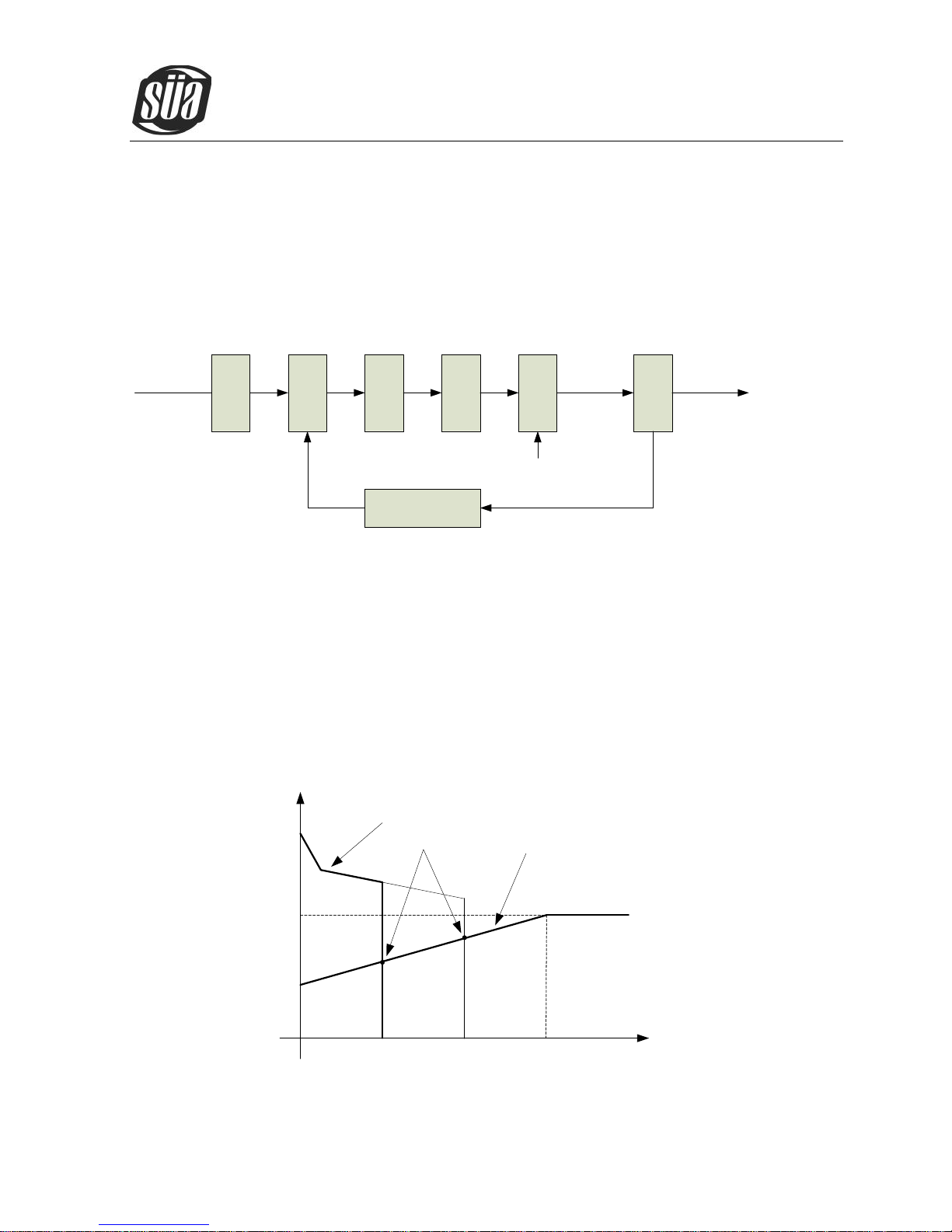
2.2 Working Principle
The working principle of ionTig 200 AC/DC welding machines is shown as the following figure.
ionTig 200 AC/DC
Copyright © Mundaka Welding & Gases, Inc.
10
Single-phase 220V work frequency AC is rectified into DC (about 312V), then is converted to medium
frequency AC (about 20KHz) by inverter device (IGBT module), after reducing voltage by medium
transformer (the main transformer) and rectifying by medium frequency rectifier (fast recovery diodes),
then is outputted DC or AC by selecting IGBT module. The circuit adopts current feedback control
technology to insure current output stably. Meanwhile, the welding current parameter can be adjusted
continuously and steplessly to meet with the requirements of welding craft.
Rectif
ier
Invert
er
Trans
forme
r
Rectif
ier
Hall
devic
e
Current feedback
control
Single-phase, AC
DC
AC DC
220V,50Hz
AC
Invert
er
AC or DC
Control signal
AC or DC
2.3 Volt-Ampere Characteristic
ionTig 200 AC/DCwelding machine has an excellent volt-ampere characteristic, whose graph is shown
as the following figure. The relation between the conventional rated loading voltage U2 and the
conventional welding current I2 is as follows:
When I2≤600A,U2=10+0.04I2(V); When I2¬>600A,U2=34(V).
67
34
10
0 600
I2(A)
U2(V)
Working
point
Volt-ampere characteristic
The relation between the
conventional loading
voltage and welding current

ionTig 200 AC/DC
Copyright © Mundaka Welding & Gases, Inc.
11
3. Installation and Adjustment
3.1 Parameters
Models
Parameters
ionTig 200 AC/DC
Input power
1~220±10%,50Hz
Rated input current(A)
35.4(TIG)
39.5(MMA)
Rated input power(KW)
5.2(TIG)
6.4(MMA)
Power factor
0.68
Max no-load voltage(V)
66
Adjustment range of start
current(A)
TIG
MMA
AC
D
C
AC
DC
HF
LIFT
5~
weldi
ng
curre
nt
—
—
10~
welding
current
30~
welding
current
Adjustment range of
welding current(A)
10~
200
30~
2005~200
10~
170
5~170
Adjustment range of Crater
arc current(A)
10~
200
30~
2005~200
10~
170
5~170
Adjustment range of
downslope time(S)
0~10
Pre-gas time(S)
0.1~1
Adjustment range of
post-gas time(S)
0.1~10
Clearance effect(%)
15~50
Efficiency
Duty cycle ( 40℃ , 10
minutes)
AC
DC
25% 200A
25% 200A
60% 90A
60% 110A
100% 70A
100% 80A
Protection class
IP23S
 Loading...