

Sua ionMig 250 Operation Manual
ionMig 250
IMPORTANT: Read this Owner’s Manual Completely before attempting to use this
equipment. Save this manual and keep it handy for quick reference. Pay particular
attention to the safety instructions we have provided for your protection. Contact your
distributor if you do not fully understand this manual.
ionMig 250
INVERTER IBGT – MIG WELDING MACHINE
OPERATION MANUAL
Copyright © Mundaka Welding & Gases, Inc.

ionMig 250
2
CONTENT
1. SAFETY ................................................................................................................................... 3
2. GENERAL DESCRIPTION ....................................................................................................... 5
3. CIRCUIT DIAGRAM ................................................................................................................. 6
4. MAIN PARAMETER ................................................................................................................. 7
5. PANEL INSTRUCTION ............................................................................................................ 8
5.1 Front panel instruction......................................................................................................... 8
5.2 Back panel instruction ....................................................................................................... 10
5.3 Middle panel instruction .................................................................................................... 11
6. INSTALLATION & OPERATION ............................................................................................ 12
6.1 Input cable connection....................................................................................................... 12
6.2.1 Arc welding installation................................................................................................... 12
6.2.2 Sketch map of installation: .......................................................................................... 13
6.2.3 Operation ......................................................................................................................... 14
6.3.1 MIG welding installation .................................................................................................. 14
6.3.2 Sketch map of installation: .......................................................................................... 15
6.3.3 Operation: ..................................................................................................................... 15
6.4.1 No gas, self-protection welding installation: ................................................................. 16
6.4.2 Sketch map of installation: .......................................................................................... 17
6.4.3 Operation: ........................................................................................................................ 17
7. CAUTION ............................................................................................................................... 18
7.1 Working Environment ........................................................................................................ 18
7.2 Good Ventilation ................................................................................................................. 18
7.3 Over-voltage is forbidden .................................................................................................. 18
7. 4 Over-load is forbidden ...................................................................................................... 19
7. 5 Over-heating Protection .................................................................................................... 19
8. MAINTENANCE ..................................................................................................................... 19
9. TROUBLESHOOTING ........................................................................................................... 20
Copyright © Mundaka Welding & Gases, Inc.
ionMig 250
3
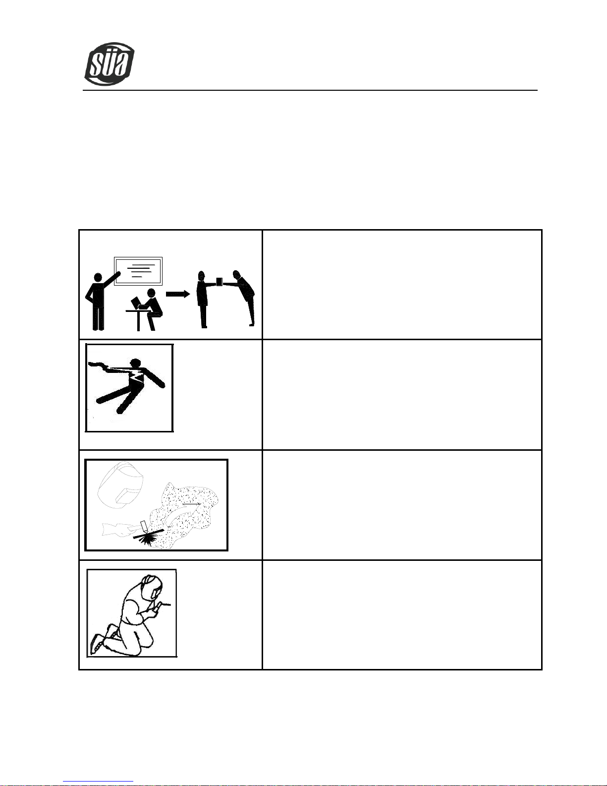
Professional training is needed before operating the
machine.
·Use labor protection welding supplies authorized by national
security supervision department.
·The operator must be special personnel with a valid "metal
welding (OFC) operations" operation certificate.
·Cut off power before maintenance or repair.
Electric shock—may lead to serious injury or even
death.
·Install grounding device according to the application criteria.
·Never touch the live parts when skin bared or wearing wet
gloves/clothes.
·Make sure that you are insulated from the ground and
workpiece.
·Make sure that your working position is safe.
Smoke& gas—may be harmful to health.
·Keep the head away smoke and gas to avoid inhalation of
exhaust gas from welding.
·Keep the working environment in good ventilation with
exhaust or ventilation equipment when welding.
Arc radiation—may damage eyes or burn skin.
·Wear Suitable welding masks and protective clothing to
protect your eyes and body.
·Use suitable masks or screens to protect spectators from
harm.
1. SAFETY
Welding is dangerous, and may cause damage to you and others, so take good protection when welding.
For details, please refer to the operator safety guidelines in conformity with the accident prevention
requirements of the manufacturer.
Copyright © Mundaka Welding & Gases, Inc.
ionMig 250
4
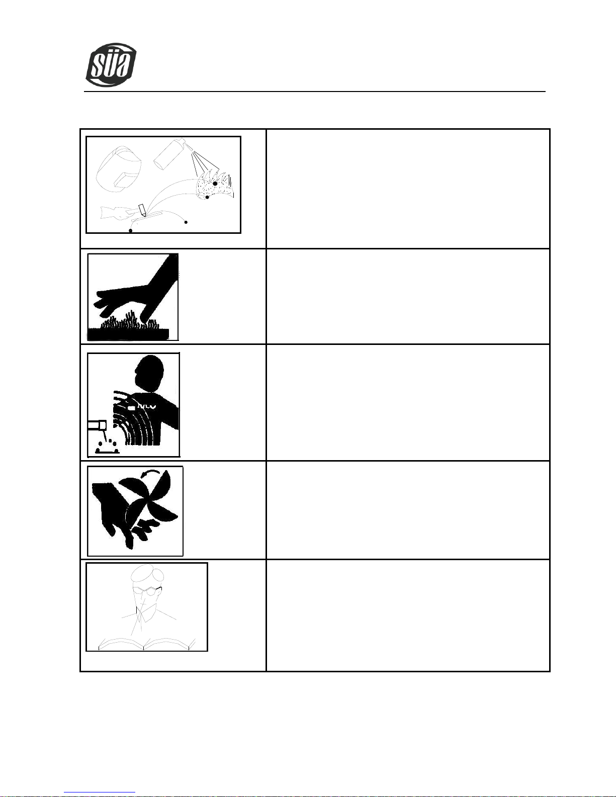
Improper operation may cause fire or explosion.
·Welding sparks may result in a fire, so please make sure no
combustible materials nearby and pay attention to fire
safety.
·Have a fire extinguisher nearby, and have a trained person to
use it.
·Airtight container welding is forbidden
·Pipe thaw with this machine is forbidden.
Hot workpiece may cause severe scalding.
·Don’t contact hot workpiece with bare hands.
·Cooling is needed during continuous use of the welding
torch.
Magnetic fields affect cardiac pacemaker.
·Pacemaker users should be away from the welding spot
before medical consultation.
Moving parts may lead to personal injury.
·Keep yourself away from moving parts such as fan.
·All doors, panels, covers and other protective devices should
be closed and in place.
Machine fault—seek professional help when
encountering any difficulties.
·Consult the relevant contents of this manual If you encounter
any difficulties in installation and operation.
·Contact the service center of your supplier to seek
professional help If you still cannot fully understand after
reading the manual or still cannot solve the problem
according to the manual.
Copyright © Mundaka Welding & Gases, Inc.

ionMig 250
5
2. GENERAL DESCRIPTION
Triple function machine that contain MIG welding, arc welding and no gas self-protection
welding.
Use IGBT with unique control method as inverter power device for increase the reliability
of welding machine.
The duty cycle is so high that can weld long time.
Closed loop feedback control, constant voltage output, fit for wide voltage range (±15%)
Adjustable welding voltage and current, excellent welding characteristics.
MIG welding use the unique welding dynamic characteristic control circuit, stable welding
arc, and little splash, beautiful shaping, high welding efficiency.
Function of removing the molten ball after welding available, high no-load, slow wire
feeding, high successful rate of arc starting.
The current of arc welding is stable, lift arc performance is excellent, and any model
welding rod is available.
Inverter frequency is 20 KHz, greatly reducing the volume and weight of the welder.
Great reduction in metal loss obviously enhances the welding efficiency and energy
saving effect.
Switching frequency is beyond audio range, which almost eliminates noise pollution.
Copyright © Mundaka Welding & Gases, Inc.
ionMig 250
6
A
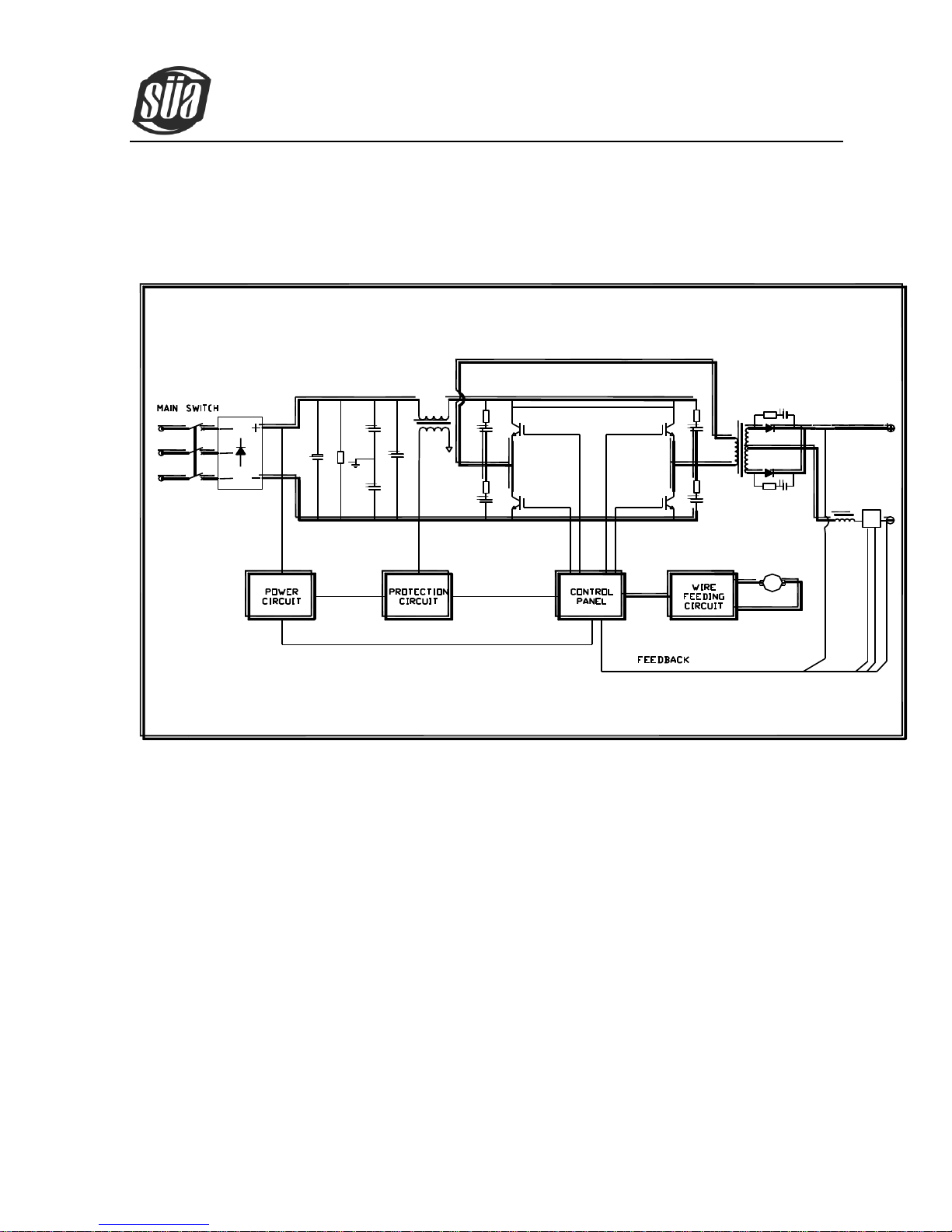
3. CIRCUIT DIAGRAM
Copyright © Mundaka Welding & Gases, Inc.
ionMig 250
7
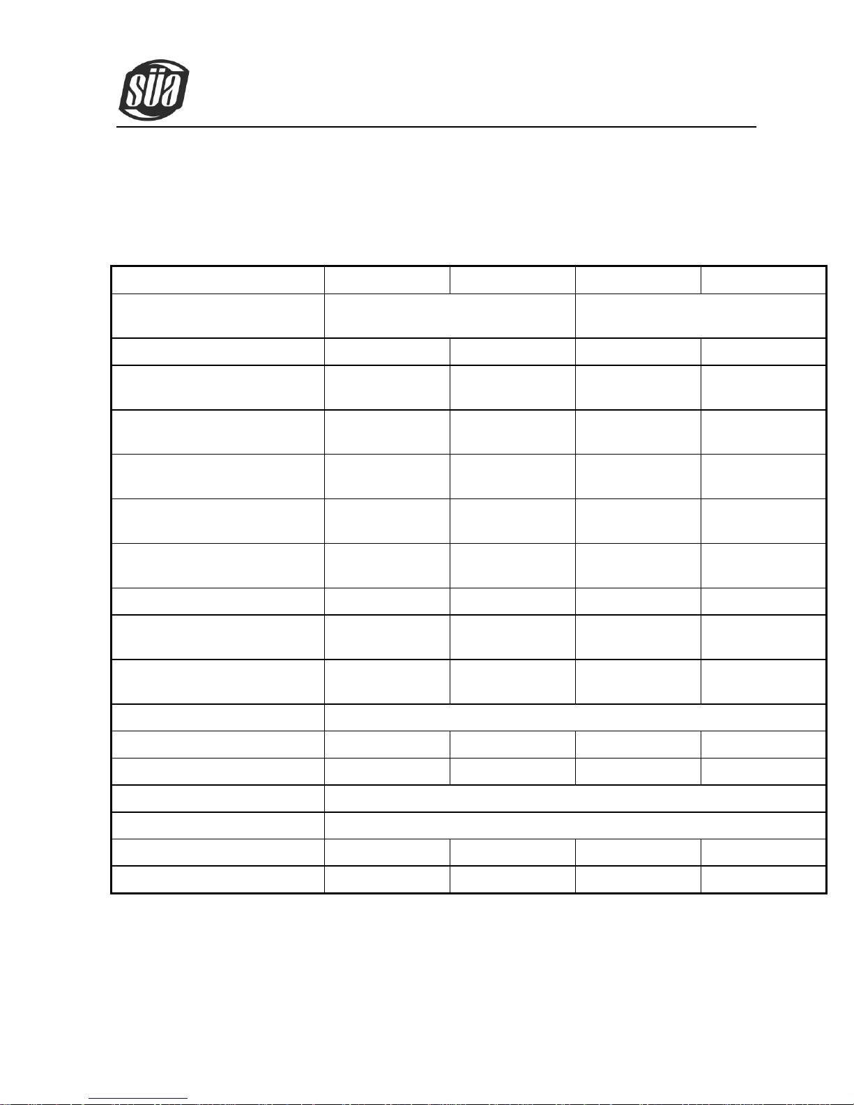
TYPE
MIG200
MIG250
MIG200MY
MIG250MY
Input voltage (V)
Single-phase
AC230V±15%,50/60Hz
3-phase
AC410V±15%,50/60Hz
Rated input current (A)
33
45
16
22
Rated power supply capacity
(KVA)
7.5
10.4
6.6
9.2
Recommended fuse capacity
(A)
60
70
70
70
Arc welding current adjustment
range (A)
10~200
10~250
10~200
10~250
Gas protection welding current
adjustment range (A)
25~200
25~250
25~200
25~250
Gas protection welding voltage
adjustment range (V)
11~27
11~29
11~27
11~29
No-load voltage (V)
52
54
52
54
Feed speed adjustment range
(m/min)
1.5~16
1.5~16
1.5~16
1.5~16
Welding wire diameter
applicable (mm)
0.6/0.8/0.9 /1.0
0.6/0.8/0.9 /1.0
0.6/0.8/0.9 /1.0
0.6/0.8/0.9 /1.0
Rated duty cycle 40 °C
35% @ 250 Amp
Efficiency (%)
85
85
85
85
Power factor
0.75
0.75
0.85
0.85
Protection class
IP21S
Insulation class
F
Size (mm)
880×296×616
880×296×616
880×296×616
880×296×616
Weight (Kg)
75
77
75
77
4. MAIN PARAMETER
Copyright © Mundaka Welding & Gases, Inc.
 Loading...