

Sua ionMig 200 PFC Operation Manual
ionMig 200 PFC
Copyright © Mundaka Welding & Gases, Inc.
ionMig 200 PFC
INVERTER IBGT – MIG WELDING MACHINE
OPERATION MANUAL
IMPORTANT: Read this Owner’s Manual Completely before attempting to use this
equipment. Save this manual and keep it handy for quick reference. Pay particular
attention to the safety instructions we have provided for your protection. Contact your
distributor if you do not fully understand this manual.

ionMig 200 PFC
Copyright © Mundaka Welding & Gases, Inc.
2
CONTENT
1. Safety.............................................................................................................................................. 3
1.1 Signal Explanation.......................................................................................................................3
1.2 Arc Welding Damage...................................................................................................................5
1.3 The knowledge of Electric and Magnetic Fields........................................................................5
2. Overview.........................................................................................................................................6
2.1 Brief Introduction......................................................................................................................... 6
2.2 Working Principle ........................................................................................................................ 7
3.1 Parameters ................................................................................................................................. 10
3.2 Duty cycle and Over-heat...........................................................................................................11
3.3 Equipment Connection.............................................................................................................. 12
3.4 Maintenance of MIG Gun mechanism ...................................................................................... 13
3.4.1 Dissection graphics for the MIG GUN ................................................................................... 13
3.4.2 The parts list for the MIG GUN............................................................................................... 14
3.4.3 The operation for the MIG GUN ............................................................................................. 14
4. Operation......................................................................................................................................16
4.1 Layout for the front and rear panel .......................................................................................... 16
4.2 Welding operation...................................................................................................................... 18
4.2.1 MIG mode operation:..............................................................................................................18
4.2.2 TIG mode operation:............................................................................................................... 21
4.2.3 MMA mode operation: ............................................................................................................22
4.3 Welding parameters................................................................................................................... 22
4 .4 Operation environment.............................................................................................................22
5 Maintenance & Troubleshooting..................................................................................................23
5.1 Maintenance............................................................................................................................... 23
5.2 Troubleshooting......................................................................................................................... 25
5.3 Electrical schematic drawing.................................................................................................... 27
ionMig 200 PFC
Copyright © Mundaka Welding & Gases, Inc.
3
1. Safety
1.1 Signal Explanation
Welding is dangerous, and may cause damage to you and others, so take good protection when
welding. For details, please refer to the operator safety guidelines in conformity with the accident
prevention requirements of the manufacturer.
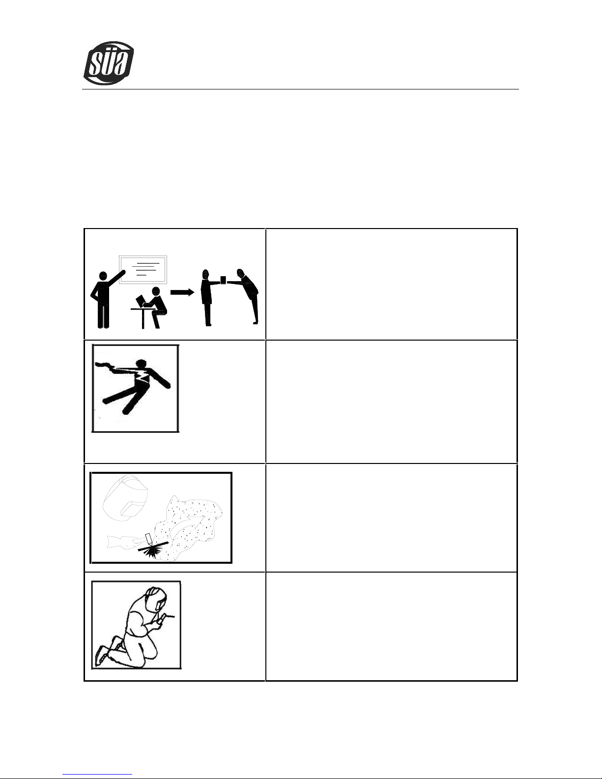
Professional training is needed before operating
the machine.
·Use labor protection welding supplies authorized by
national security supervision department.
·The operator must be special personnel with a valid
"metal welding (OFC) operations" operation
certificate.
·Cut off power before maintenance or repair.
Electric shock—may lead to serious injury or even
death.
·Install ground device according to the application
criteria.
·Never touch the live parts when skin bared or wearing
wet gloves/clothes.
·Make sure that you are insulated from the ground and
workpiece.
·Make sure that your working position is safe.
Smoke& gas—may be harmful to health.
·Keep the head away smoke and gas to avoid
inhalation of exhaust gas from welding.
·Keep the working environment in good
ventilation with exhaust or ventilation equipment
when welding.
Arc radiation—may damage eyes or burn skin.
·Wear Suitable welding masks and protective
clothing to protect your eyes and body.
·Use suitable masks or screens to protect
spectators from harm.

ionMig 200 PFC
Copyright © Mundaka Welding & Gases, Inc.
4
Improper operation may cause fire or explosion.
·Welding sparks may result in a fire, so please
make sure no combustible materials nearby and
pay attention to fire safety.
·Have a fire extinguisher nearby, and have a
trained person to use it.
·Airtight container welding is forbidden
·Pipe thaw with this machine is forbidden.
Hot workpiece may cause severe scalding.
·Don’t contact hot workpiece with bare hands.
·Cooling is needed during continuous use of the
welding torch.
Magnetic fields affect cardiac pacemaker.
·Pacemaker users should be away from the
welding spot before medical consultation.
Moving parts may lead to personal injury.
·Keep yourself away from moving parts such as
fan.
·All doors, panels, covers and other protective
devices should be closed and in place.
Machine fault—seek professional help when
encountering any difficulties.
·Consult the relevant contents of this manual If
you encounter any difficulties in installation and
operation.
·Contact the service center of your supplier to
seek professional help If you still cannot fully
understand after reading the manual or still
cannot solve the problem according to the
manual.

ionMig 200 PFC
Copyright © Mundaka Welding & Gases, Inc.
5
1.2 Arc Welding Damage
The following signals and word explanations are to some damages for your body or others
happening on the welding operation. While seeing these, please remind of yourself or others to
be dangerous.
Only ones who are trained professionally can install, debug, operate, maintain and repair the
equipment.
During the operation, non-concerned people should be lift, especially for children.
After shut off the machine power, please maintain and examine the equipment according to §5
because of the DC voltage existing in the electrolytic capacitors.
1.3 The knowledge of Electric and Magnetic Fields
Electric current flowing through any conductor causes localized Electric and Magnetic Fields
(EMF). The discussion on the effect of EMF is ongoing all the world. Up to now, no material
evidences show that EMF may have effects on health. However, the research on damage of
EMF is still ongoing. Before any conclusion, we should minimize exposure to EMF as few as
possible.
In order to minimize EMF, we should use the following procedures:
o Route the electrode and work cables together – Secure them with tape when possible.
o All cables should be put away and far from the operator.
o Never coil the power cable around your body.
o Make sure welding machine and power cable to be far away from the operator as far as
possible according to the actual circumstance.
o Connect the work cable to the workpiece as close as possible to the area being welded.
The people with heart-pacemaker should be away from the welding area.

ionMig 200 PFC
Copyright © Mundaka Welding & Gases, Inc.
6
2. Overview
2.1 Brief Introduction
MIG SERIES arc welding machine adopts the latest pulse width modulation (PWM) technology and
insulated gate bipolar transistor (IGBT) power module, which can change work frequency to medium
frequency so as to replace the traditional hulking work frequency transformer with the cabinet medium
frequency transformer. Thus, it is characterized with portable, small size, light weight, low consumption
and etc.
MIG SERIES arc welding machine uses Mix gas as shielded gas to realize gas shielded welding,
active gas(Ar+O2、Ar+CO2) as shielded gas to realize MAG welding and inactive gas(Ar)as
shielded gas to realize MIG welding.
MIG SERIESarc welding machine has automatic protection functions with intelligent to over-voltage,
over-current and over-heat. If any one of the above problems happens, the alarm lamp on the front
panel will be lighted and output current will be shut off automatically to protect itself and prolong the
equipment using life.
MIG SERIES Features:
1. Digital control system, real-time display the welding parameters;
2. High performance multifunction power source (MMA/MIG/MAG);
3. Waveform control, stable welding arc;
4. IGBT technology, low power dissipation;
5. Rated duty circle is 40 % (40℃).
MULTIMIG 160/200 has another feature: Synergic control of the welding current and voltage.
MIG SERIES arc welding machine is suitable for all positions welding for various plates made of
stainless steel, carbon steel, alloyed steel, copper, titanium, etc, which is also applied to pipe
ionMig 200 PFC
Copyright © Mundaka Welding & Gases, Inc.
7
installment, mold mend, petrochemical, architecture decoration, car repair, bicycle, handicraft and
common manufacture.
MAG--Metal Active Gas Welding
MIG--Metal Insert Gas Welding
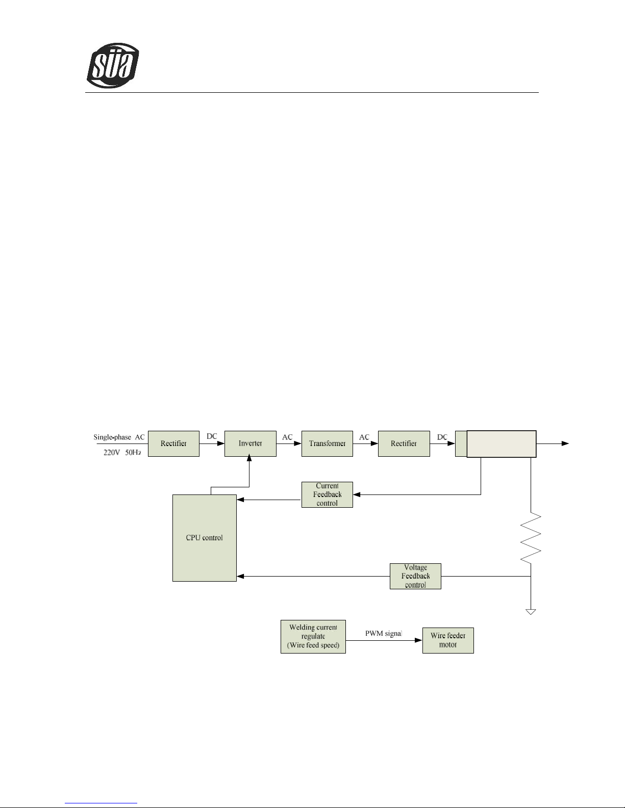
2.2 Working Principle
The working principle of MIG SERIES arc welding machine is shown as the following figure.
Single-phase 220V work frequency AC is rectified into DC(350V), then is converted to
medium frequency AC (about 40KHz) by inverter device (IGBT), after reducing voltage by
medium transformer (the main transformer) and rectifying by medium frequency rectifier (fast
recovery diodes), and is outputted by inductance filtering. The circuit adopts current feedback
control technology to insure current output stably when MMA or TIG. And adopts voltage
feedback control technology to insure voltage output stably when MIG. Meanwhile, the
welding current parameter can be adjusted continuously and infinitely to meet with the
requirements of welding craft.
Current sensor
ionMig 200 PFC
Copyright © Mundaka Welding & Gases, Inc.
8
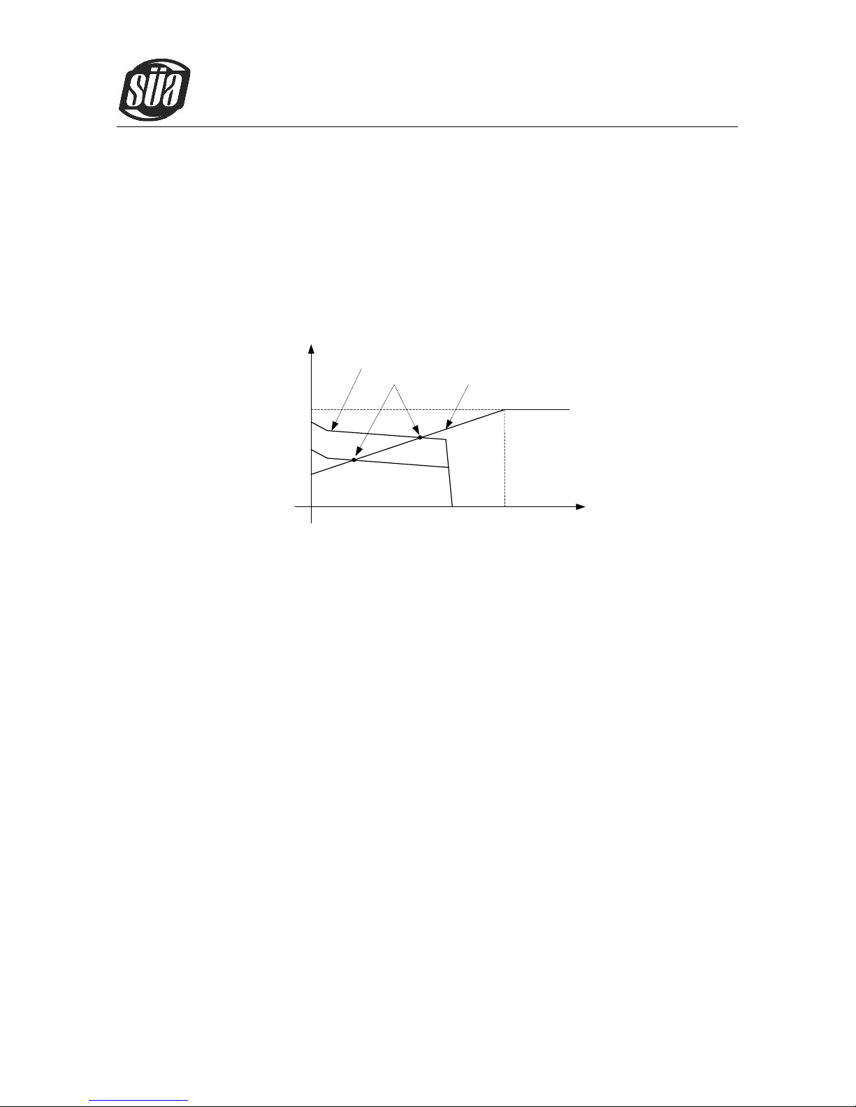
2.3 Volt-Ampere Characteristic
MIG SERIES welding machine has an excellent volt-ampere characteristic, whose graph is shown
as the following figure. The relation between the rated loading voltage U2and welding current I2is as
follows: U2=14+0.05I2(V)
44
14
0 600
Io(A)
Uo(V)
Working point
Volt-ampere characteristic
The relation between the rated loading
voltage and welding current
ionMig 200 PFC
Copyright © Mundaka Welding & Gases, Inc.
9
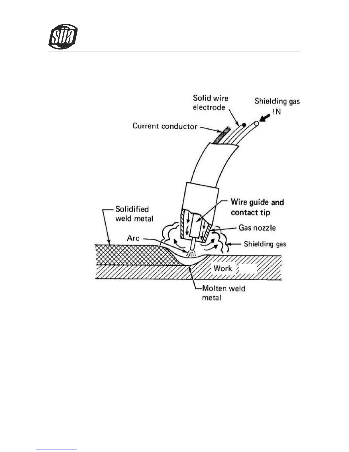
2.4 Principles of welding
 Loading...