

Page 1
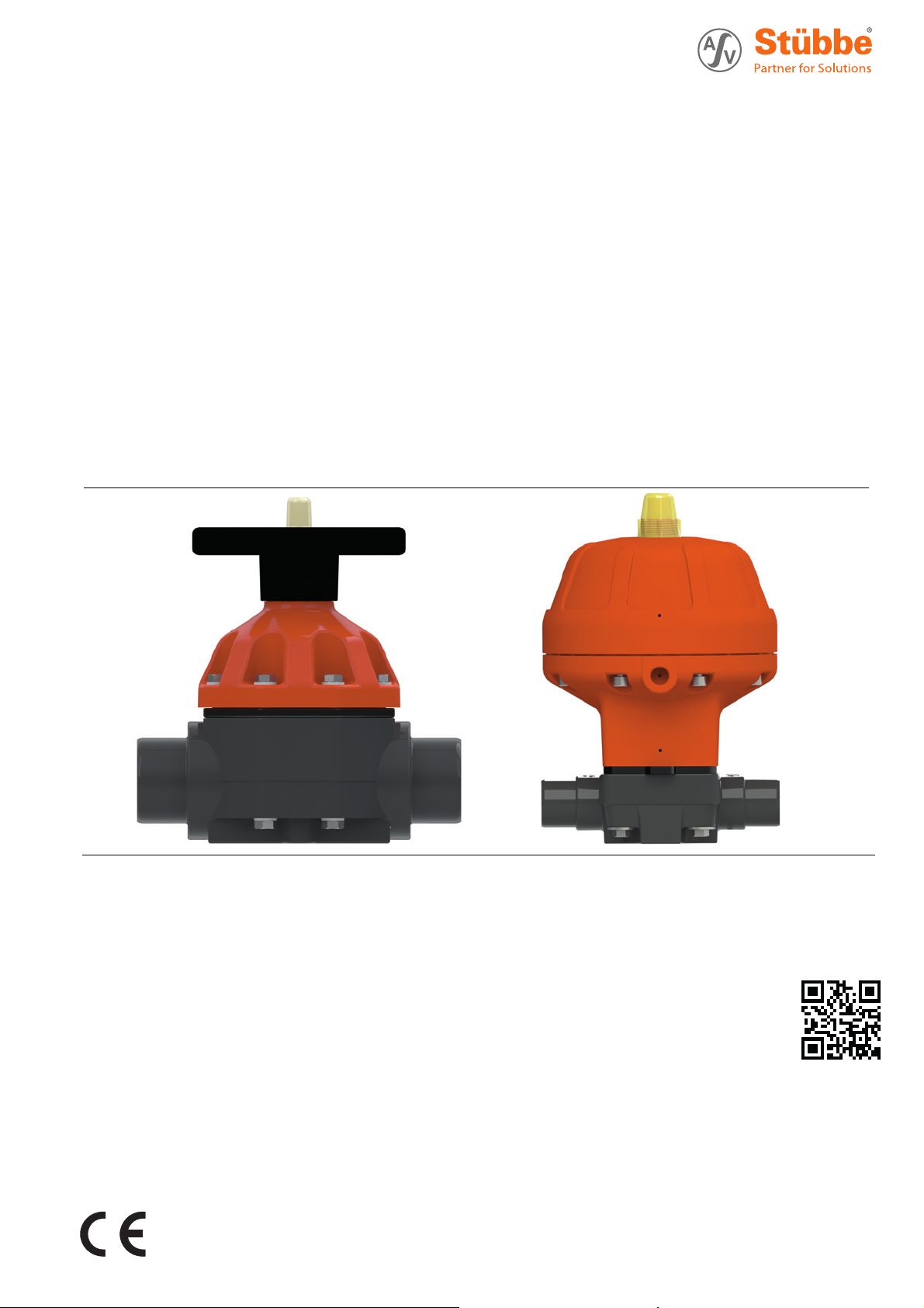
Diaphragm valve
Operating manual Series MV 310
Version BA-2017.10.26 EN
Print-No. 300 719
TR MA DE Rev001
ASV Stübbe GmbH & Co. KG
Hollwieser Straße 5
32602 Vlotho
Germany
Phone: +49 (0) 5733-799-0
Fax: +49 (0) 5733-799-5000
E-mail: contact@asv-stuebbe.de
Internet: www.asv-stuebbe.com
Subject to technical modifications.
Read carefully before use.
Save for future use.
Page 2

Table of contents
Table of contents
1 About this document ............................... 4
1.1 Target groups .................... ............. 4
1.2 Other applicable documents ......... ....... 4
1.3 Warnings and symbols ........ ............... 4
2 Safety instructions ............................... .. 5
2.1 Intended use .. ................................ 5
2.2 General safety instructions .................. 5
2.2.1 Obligations of the operating company .. .. . . 5
2.2.2 Obligations of personnel ........ ............. 5
2.3 Specific hazards ....... ....................... 5
2.3.1 Hazardous media ..................... ....... 5
3 Layout and Function ............................... 6
3.1 Marking ............................. .......... 6
3.1.1 Name plate ......................... .......... 6
3.2 Assembly ..................................... 6
4 Transport, Storage and Disposal ................. 7
4.1 Unpacking and inspection on delivery .. . . . . 7
4.2 Transportation ................................ 7
4.3 Storage ....... ................................ 7
4.4 Disposal .................. ..................... 7
5 Installation and connection ....................... 8
5.1 Preparing for installation .............. ....... 8
5.1.1 Check operating conditions ................. 8
5.2 Planning pipelines ............................ 8
5.2.1 Designing pipelines .......................... 8
5.3 Installing fitting in pipe ....................... 8
5.3.1 Connection with solvent welding/butt-weld
spigot ends ...................... ............. 8
5.3.2 Connection with flange .................. .... 8
5.3.3 Connection with union nut and insert . . . . . .. 8
5.4 Connecting the drive ......................... 9
5.4.1 Installing limit switch ......................... 10
5.4.2 Pneumatic connection .. ..................... 10
5.4.3 Checking the function of the drive .......... 10
5.5 Performing the hydrostatic test .............. 10
6Operation ............................... ............. 11
6.1 Commissioning ............................... 11
6.2 Manual operation ............................. 11
6.3 Emergency operation .................... .... 11
6.4 Set lift ....................... .................. 11
7 Maintenance ....................... .................. 12
7.1 Servicing ......................... ............. 12
7.2 Maintenance ................ .................. 12
7.2.1 Removing fitting .............................. 12
7.2.2 Fixing leaks in the port ....................... 13
7.3 Replacem
ent parts and return ..............
13
8 Troubleshooting .................................... 14
9 Appendix ................................... .......... 15
9.1 Technical specifications ...................... 15
9.1.1 Mechanical specifications ............ ....... 15
9.1.2 Control air connections ...................... 15
9.2 Tightening torques .................... ....... 16
9.2.1 Housing ....................................... 16
9.2.2 Flange connection ......... .................. 16
9.3 Accessories ................................... 16
9.4 Parts .......................................... 17
9.4.1 Part name DN 15–DN 100, manual .. . . .. . . . 17
9.4.2 Part name DN 15–DN 50, pneumatic .. . . .. . 18
9.4.3 Part name DN 65, pneumatic .. . . . . . .. . . . . . . 20
9.4.4 Part designation DN 80–100 . . . .. . . . . . .. . . . . 21
List of figures
Fig. 1 Name plate (example) ....................... 6
Fig. 2 Structure (manual operation) ................ 6
Fig. 3 Structure (pneumatic operation) ............ 6
Fig. 4 Limit switch, type VCSP ..................... 9
Fig. 5 Limit switch, type Nj2–V3–N ................ 9
Fig. 6 Limit switch, type NBB2–V3–E2 ............ 9
Fig. 7 Compressed air, control function NC ....... 9
Fig. 8 Compressed air, control function NO
DA ................... .......................... 9
Fig. 9 Tightening torque housing screw ....... .... 16
Fig. 10 Part name DN 15–DN 50 .......... .......... 17
Fig. 11 Part designation DN 65–DN 100 . . . . . . .. .. . . 17
Fig. 12 DN 15–DN 50, pneumatic, va lve function NC
without lift limit ................. ............... 18
Fig. 13 DN 15–DN 50, pneumatic, va lve function NC
with lift limit ................. .................. 18
Fig. 14 DN 15–DN 50, pneumatic, valve function
NO ........................... .................. 19
Fig. 15 DN 15–DN 50, pneumatic, valve function
DA ................... .......................... 19
Fig. 16 Part name DN 65, pneumatic ............... 20
Fig. 17 Part name DN 80 ............................. 21
Fig. 18 Part name DN 100 ............ ............... 21
Fig. 19 Part name DN 80, NO DA ................... 22
Fig. 20 Part name DN 100, NO DA .................. 22
2 MV 310 BA-2017.10.26 EN 300 719
Page 3

List of tables
Tab. 1 Other application documents, purpose and
where found ............................. ..... 4
Tab. 2 Warnings and symbols ....................... 4
Tab. 3 Compressed air connection ...... ........... 10
Tab. 4 Diaphragm maintenance interval ........... 12
Tab. 5 Troubleshooting .............................. 14
Tab. 6 Mechanical speci fications ........ ........... 15
Tab. 7 Tightening torques housing .................. 16
Tab. 8 Tightening torque of flange connectio n . . . .. 16
Tab. 9 Accessories ................................... 16
Tab. 10 Part number and designation DN 15 –
50 ........................... ................... 17
Tab. 11 Part number and designation DN 65
–100 .......... ................................. 17
Tab. 12 Part number and designation DN 15–DN 50,
pneumatic, valve function NC ......... ..... 18
Tab. 13 Part number and designation DN 15–DN 50,
pneumatic, valve function NO and DA .. . . .. 19
Tab. 14 Part number and designation DN 65,
pneumatic ............................. ........ 20
Tab. 15 Part number and designation DN 80-100,
NC .. ........................................... 21
Tab. 16 Part number and de signation DN 8 0-100, NO
DA .................. ........................... 22
Table of contents
300 719 BA-2017.10.26 EN MV 310 3
Page 4

About this document
1 About this document
This manual
• ispartofthefitting
• applies to all series referred to
• describes safe and proper operation during all operating
phases
1.1 Target groups
Operating company
• Responsibilities:
– Keep this manual ava ilable at the place of operatio n,
also for future use.
– Ensure that employees read and observe this manual
and other applicable documents, especially the safety
instructions and warnings.
– Observe any additional cou ntry-specific rules and reg-
ulations that relate to the system.
Qualified personnel, fitter
• Mechani cs qualification:
–Qualified employees with additiona l training for fitting
therespectivepipework
• Electrical q ualification:
–Qualified electrician
• Respon s ibi lity:
– Read, observe and follow this manual and the other
applicable documents, especially all safety instructions
and warnings.
1.2 Other applicable documents
Resistance lists
Resistance of materials used to chemicals
www.asv-stuebbe.de/pdf_resistance/300051.pdf
Data sheet
Technical data and conditions of operation
www.asv-stuebbe.de/pdf_datasheets/300848.pdf
CE declaration of conformity
Conformity with standards
www.asv-stuebbe.de/pdf_DOC/300168.pdf
Tab. 1 Other application documents, purpose
and where found
1.3 Warnings and symbols
Symbol
1., 2., ... Multiple-step instructions
→
Tab. 2 Warnings and symbols
Meaning
• Immediate acute risk
• Death, serious bodily harm
• Potentially acute risk
• Death, serious bodily harm
• Potentially hazardous situation
• Minor injury
• Potentially hazar
• Material damage
Safety warning sign
Take no te of all informatio n
highlighted by the safety warning
sign and follow the instructions to
avoid injury or death.
Instruction
Precondition
Cross reference
Information, notes
dous situa tion
4 MV 310 BA-2017.10.26 EN 300 719
Page 5

2 Safety instructions
Safety instructions
The manufacturer accepts no liability for damages caused
by disregarding any of the docu mentation.
2.1 Intended use
•Onlyusethefitting to shut off pipes for appropriate media
(→ Resistance list).
• Adhere to the operating limits (→ Data sheet).
2.2 General safety instructions
Read and observe the following re gulations before carrying
out any work.
2.2.1 Obligations of the operating company
Safety-conscious working
• Only operate the fittingifitisinperfecttechnical condition
and only use it as intended, remaining aware of safety and
risks, and adhering to the instructions in this manual.
• Ensure that the following safety aspects are observed and
monitored:
– Intended use
– Statutory or other safety and accident-prevention reg-
ulations
– Safety regulations governing the handling of haz-
ardous substances
– Applicable standards and guidelines in th e country
where the pump is operated
• Make personal protective equipment available.
2.2.2 Obligations of personnel
• Observe the instructions on the fitting and keep them legible, e.g. name plate and identification marking for fluid
connections.
• Only carry out work on the fitting if the following requirements are met:
– System is empty
– System has been flushed
– System is depressurized
– System has cooled down
– System is secured against being switched back on
again
• Do not make any modifications to the device.
2.3 Specifichazards
2.3.1 Hazardous media
• When handling hazardous media (e.g. hot, flammable,
explosive, toxic, hazardous to health or the environment),
observe the safety regu lations for the handling of hazardous substances.
• Use personal protective equipment when carrying out any
work on the fitting.
• Collect leaking pumped liquid and residues in a safe manner and dispose of in accordance with environmental regulations.
Qualified personnel
• Ensure all personne l tasked with work on the fitting have
read and understoo d this manual and all other applica
documents, especially the safety, maintenanc
information, before they start any work.
• Organ ize responsibilities, areas of competence and the
supervision of personnel.
• The following work should be carried out by specialist technicians only:
– Installation, repair and maintenance work
– Work on the electrical system
• Make sure that perso nnel to be trained only wo
fitting unde r the supervision of specialist technicia
e and repair
ble
rk on the
ns.
300 719 BA-2017.10.26 EN MV 310 5
Page 6
Layout and Function
3 Layout and Function
3.1 Marking
3.1.1 Name plate
1
2
1
MV310
2
3
4
Fig. 1 Name plate (exa mple)
1Type
2IDnumber
3 Nominal pressure [bar] / Nominal diameter [mm]
4 Materials (valve body, diaphragm, other gaskets)
5 Date of manufacture - Series numbe r
Id No
PN/DN
PP • PTFE • FPM
145039
6 / 15
1407-87345
5
3.2 Assembly
Compressed air operated diaphragm valve for shutting off
pipelines or regulating systems.
• Optional flow direction
• Valve lift OPEN/CLOSE
• Option al installation position
• Valve functions
–Normallyclosed(NC)
– Normally open (NO)
– Double acting (DA)
3
4
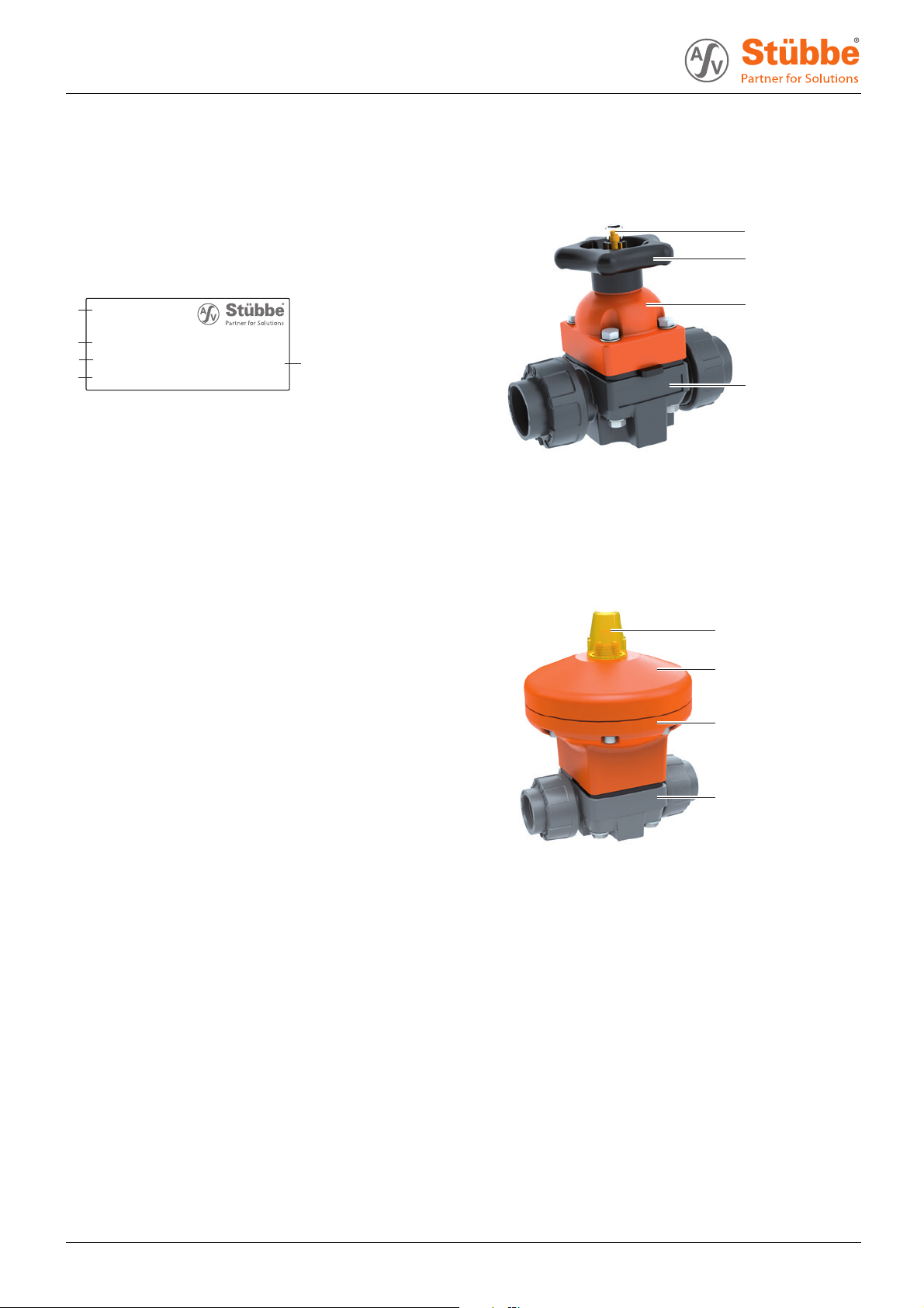
Fig. 2 Structure (manual operation)
1 Indicator cap
2 Handwheel
3 Upper part of housing
4 Valve body
1
2
3
4
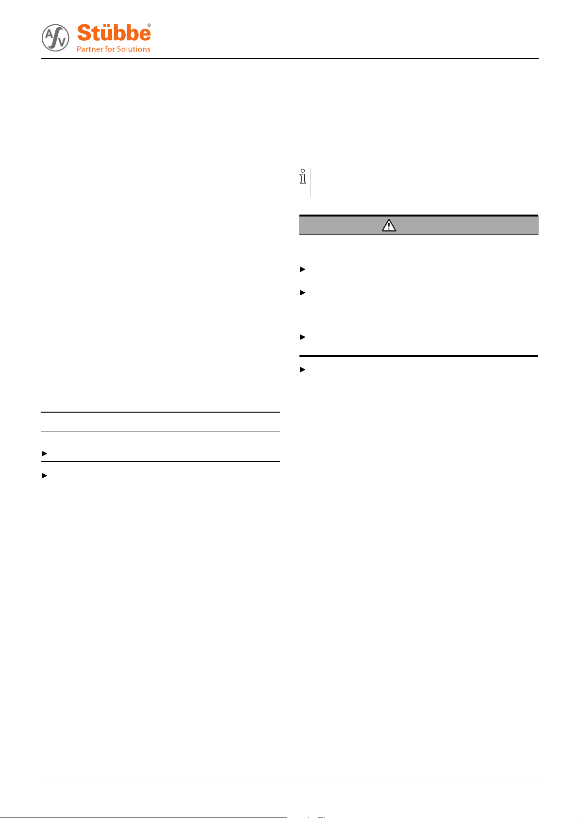
Fig. 3 Structure (pneumatic operation)
1 Indicator cap
2 Upper part of drive housing
3 Lower part of drive housing
4 Valve body
6 MV 310 BA-2017.10.26 EN 300 719
Page 7
4 Transport, Storage
and Disposal
Transport, Storage and Disposal
4.1 Unpacking and insp ection on delivery
1. Unpack the fitting when received and inspect it for transportation damage.
2. Report any transportation damage to the manufacturer
immediately.
3. Ensure that the information on the name plate agrees with
the order/design data.
4. With immediate installation, dispose of packaging material
according to local regulations.
– For later installation, leave the fitting in the original
packaging.
4.2 Transportation
1. If possible, transport fitting(includingdrive)intheoriginal
packaging.
2. Lift fitting manually for transport. For weight specifications
(→ Data sheet).
4.3 Storage
NOTE
Material damage due to inappropriate storage!
Store the fitting properly.
4.4 Disposal
Plastic parts can be contaminated by poisonous or radioactive media to such an extent that cleaning wil l not be suffi-
cient.
WARNING
Risk of poisoning and environmental damage from
medium!
Use personal protective equipment when carrying out any
work on the fitting.
Before disposing of the fitting:
– Collect escaping medium and dispose separately
according to local regulations.
– Neutralize residues of med ium in the fitting.
Remove plastic parts and dispose of them in accordance
with local regulations.
Dispose of the fitting in accordance with local regulations.
Make sure the storage room meets the following conditions:
–Dry
– Frost-free
– Vibration-free
– Not in direct sunlight
– Storage temperature +10 °C to +60 °C
300 719 BA-2017.10.26 EN MV 310 7
Page 8

Installation and connection
5 Installation and connection
5.1 Preparing for installation
5.1.1 Check operating conditions
1. Ensure the design of the fitting is consistent with the purpose intended:
– Materials used (→ Type plate).
–Medium(→ Order and design data).
2. Ensure the required operating conditions are met:
– Resistance of body and seal material to the medium
(→ Resistance lists).
– Media temp erature (→ Data sheet).
– Operating pressure (→ Data sheet).
3. Consult with the manufacturer regarding any other use of
the device.
5.2 Planning pipelines
5.2.1 Designing pipelines
WARNING
Risk of poisoning and environmental damage from
medium!
Leaks due to impermissible pipework forces.
Ensure that the fitting is not subject to any pulling or thrusting forces or bending moments.
5.3 Installing fittinginpipe
WARNING
Risk of poisoning and environmental damage from
medium!
Leak due to faulty installation.
Installation work on the pipes should only be performed
by technicians who have been specially trained for the
pipework in question.
NOTE
Material damage due to contamination of the fitting!
Make sure no contamination reaches the fitting.
Flush the pipe with a neutral medium.
The fittingisinstalledaccordingtotheconnectiontypeof
the pipes.
5.3.1 Connection with solvent welding/butt-weld spigot ends
Do not connect the ASV valve body in the version “fixed
connector” by means of butt-welding.
This applies to the heating element as well as infrared buttwelding procedures.
1. Plan pipes safely:
– No pulling or thrusting forces
– No bending moments
– Adjust for changes in length due to temperature
changes (compensators, exp ansi on shanks)
– Optional flow direction
– Optional installation position and direction
2. Dimensio ns (→ Data sheet).
1. Prepare pipe ends according to connection type.
2. Adhesive ly apply or weld fitting with solvent welding/buttweld socket ends (→ manufacturer specifications).
5.3.2 Connection w ith flan ge
1. Prepare pipe ends according to connection type.
2. Radial ly push the fitting and flat seal between the flange
ends.
3. Bolt fitting and flange with flange screws, nuts and washers.
While doing so, observe tightening torques: (→ Ta b l e
8 Tightening torque of flange connection, Page 16).
5.3.3 Connection with union nut and insert
1. Prepare pipe ends according to connection type.
2. Unscrew union nuts and slide over free pipe ends.
– Check mounting direction.
3. Conne c t inserts with pipe ends.
4. Position fitting between the pipe ends.
– Any p ositio n of the compressed air drive
5. Hand-tighten the union nut.
8 MV 310 BA-2017.10.26 EN 300 719
Page 9

5.4 Connecting the drive
Fig. 4 Limit switch, type VCSP
Aclosed
Bopen
Installation and connection
LL
Fig. 6 Limit switch, type NBB2–V3–E2
LLoad
Aclosed
Bopen
Fig. 5 Limit switch, type Nj2–V3–N
Aclosed
Bopen
A
Fig. 7 C ompressed air, control function NC
A Open valve
A
B
Fig. 8 Compressed air, control functi on NO DA
A Close valve
B Open valve
300 719 BA-2017.10.26 EN MV 310 9
Page 10

Installation and connection
5.4.1 Installing limit switch
Only necessary for fittings with limit switches.
DANGER
Risk of electrocution!
All electrical work mus t be carried out by qualified electricians only.
1. Mount limit switch unit onto fi tting.
2. Connect limit switch:
– (→ Figure Limit switch, type VCSP, Page 9).
– (→ Figure Limit switch, type Nj2–V3–N, Page 9).
– (→ Figure Limit switch, type NBB2–V3–E2, Page 9).
5.4.2 Pneumatic connectio n
Solenoid pilot valves are available for control of the compressed air drive:
– 3/2-way valve for single-acting drives
– 5/2-way valve for double-acting drives
CAUTION
5.5 Performing the hydrostatic test
Pressure test using neutral medium, e.g. water.
1. Pressurize the fitting. ensuring:
– Test pressure < p ermissible system pressure
– Test pressure < 1.5 PN
– Test pressure < PN + 5 bar
2. Check the fi tting for leaks.
Risk of injury from compressed air!
All work on the compressed air system must be carried out
by qualified technicians.
Connect compressed ai r lines to the compressed air drive:
– (→ Figure Compressed air, control function NC,
Page 9).
– (→ Figure Compressed air, control function NO DA,
Page 9).
Control
pressure on
Function
Normally closed (NC)
Normally open (NO)
Double acting (DA)
Tab. 3 Compressed air connection
5.4.3 Checking the function of the drive
Open and close fitting using the pneumatic connection, the
indicator pin signals the corresponding position
– lowered: Fitting is closed
– protruding: Fitting is open
a
–open
close
close
b
–
open
10 MV 310 BA-2017.10.26 EN 300 719
Page 11

6 Operation
WARNING
Risk of injury and poisoning due to medium spraying out!
Use personal protective equipment when carrying out any
work on the fitting.
6.1 Commissioning
Fitting correctly installed and connected
1. Open and close fitting, the indicator pin sign als the corresponding position
– lowered: Fitting is closed
– protruding: Fitting is open
2. After the initial stresses due to pressure and operating temperature, check if the fitting is sealed.
6.2 Manual operation
Operation
Fitting correctly installed and connected
Operate manually operated fittings as follows (depending
on fitting size, turn 4–8 times):
– Turn handwheel clockwise: Close valve.
– Turn handwheel anti-clockwise: Open valve.
6.3 Emergency operation
Applies to pneumatically activated valves NC,
DN 15–DN 50.
Turn adjustment screw (3.8) clockwise to open the valve if
the pressure falls.
6.4 Set lift
Applies to pneumatically operated valves DN 15–DN 50,
special design with metal screw in the top part of the drive.
Turn screw (3.30) as follows to set the lift:
– Turn clockwise : Limit lift.
– Turn anti-clockwise: Increase lift.
300 719 BA-2017.10.26 EN MV 310 11
Page 12

Maintenance
7 Maintenance
WARNING
Risk of injury and poisoning due to hazardous media liquids!
Use personal protective equipment when carrying out any
work on the fitting.
7.1 Servicing
1. Visual and function check (every three months):
– Normal operating c onditions unchanged
–Noleaks
– No unusual operating noise s or vibrations
2. Ensure that fitting functions properly (opening, closing).
3. Clean the fitting with a moist cloth if necessary.
4. Retighten housing screws (→ Table 8 Tightening torque of
flange connection, Page 16).
5. Check diaphragm for wear and replace if necessary:
Max. number of
Diaphragm material
EPDM 150,000
FPM 100,000
PTFE (EPDM)
Tab. 4 Diaphragm maintenance interval
1) Applies to water at 20 °C. For different conditions
(chemicals, media that contains solids/abrasives),
shorten the maintenance intervals.
operations
100,000
1)
7.2 Maintenance
DANGER
Risk of electrocution!
All electrical work mus t be carried out by qualified electricians only.
WARNING
Risk of injury and poisoning due to hazardous or hot
media!
Use personal protective equipment when carrying out any
work on the fitting.
Safely collect the media and dispose of it in accordance
with environmental regulations.
WARNING
Risk of injury during disassembly!
Wear protective gloves, components can be very sharpedged due to wear or damage.
Remove components with springs (e.g. pneumatic drive)
carefully, since spring tension can cause componen ts to
be ejected.
7.2.1 Removing fitting
1. Ensure that:
– System is empty
– System has been flushe d
– System is depressurized
– System has cooled down
– System is secured against being switched back on
again
2. Remove fitti ng from the pipe.
3. Decontaminate fitting if required.
–Deadspaceinthefitting may still contain medium.
12 MV 310 BA-2017.10.26 EN 300 719
Page 13

Maintenance
7.2.2 Fixing leaks in the port
Depending on the fitting type, note the following drawings:
• DN 15–DN 50: (→ 9.4.2 Part name DN 15–DN 50, pneu-
matic, Page 18).
•DN65:(→ 9.4.3 Part name DN 65, pneumatic, Page 20).
• DN 80, DN 100: (→ 9.4.4 Part designation DN 80–100,
Page 21).
1. Removing fitting (→ 7.2.1 Removing fitting, Page 12).
Before removing the connection elements, note:
– For NC drives, apply compressed air pressure to
connection B to bring the drive into the open position
– For NO and DA drives, this is not necessary.
2. Depen ding on the fitting type, remove the following connection elements:
– DN 15–DN 50: Hexagon screw (5)
– DN 65: Bolt (13) and washer (12)
– DN 80, DN100: Screw (35), stud bolt (36 ), nut (37) and
washer (38)
3. Depen ding on the fi tting type, remove lift drive as follows:
– DN 15–DN 50: Remove lower part (3.1.) and upper
part (3.2) of drive housing.
– DN 65: Remove drive (1).
– DN 80, DN100: Remove upper (2) and lower part (18)
of the drive.
4. For NC drives on connection B, release compressed air.
5. Depen ding on the fitting type, screw out the following
diaphragm a nd dispose of it in an environmentally-friendly
manner:
– DN 15–DN 50: Diaphragm (2).
– DN 65: Diaphragm seal (7)
– DN 80, DN100: Diaphragm (24)
6. Depending on the fitting type, ensure that the following
pressure piece is resting freely in the ducts:
– DN 15–DN 50: Pressure piece (3.3)
– DN 65: Compressor (6)
– DN 80, DN100: Pressure piece (23)
7. Depending on the fitting type, check sealing areas on the
following valve body for damage:
– DN 15–DN 50: Valve body (1)
– DN 65: Valve body (8)
– DN 80, DN100: Valve body (25)
8. Lightly lubricate new diaphragm with special grease on top
of curvature and on thread (recommended special grease:
Syntheso ProAA2).
9. Screw diaphragm into spindle clockwise until resistance is
felt.
10. Depending on the fitting type unscrew diaphrag m until the
diaphragm hole pattern matches the following valve body
(max. 180°):
– DN 15–DN 50: Valve body (1)
– DN 65: Valve body (8)
– DN 80, DN100: Valve body (25)
11. Depending on the fitting type, screw in the following connection elements and tighten via the cross. Ensure uniform
contact pressure:
– DN 15–DN 50: Hexagon screw (5) .
– DN 65: Bolt (13) and washer (12)
– DN 80, DN100: Screw (35), stud bolt (36), nut (37) and
washer (38)
12. Depending on the fitting type, tighten the following conn ection elements with tightening torque ( → Table 8 Tightening
torque of flange connection, Page 16).:
– DN 15–DN 50: Hexagon screw (5)
–DN65:Bolt(13)
– DN 80, D N100: Screw (35) and nut (37)
7.3 Replacement parts and retu rn
1. Have the following information ready to hand when ordering spare parts (→ Type plate).
– Fitting type
– ID number
– Nominal pressure and diameter
– Body and seal material
2. Please complete and enclose the document of compliance
for returns (→ www.asv-stuebbe.com/service/downloads).
3. Only use spare parts from ASV Stübbe.
300 719 BA-2017.10.26 EN MV 310 13
Page 14

Troubleshooting
8 Troubleshooting
WARNING
Risk of injury and poisoning due to hazardous or hot
media!
Use personal protective equipment when carrying out any
work on the fitting.
Safely collect the media and dispose of it in accordance
with environmental regulations.
Consult with the ma nufacturer regarding faults which are not
identified in the following table, or which cannot be traced to
the indicated causes.
Error Possible cause
Control f unction i s not right
Medium escapes between housing and
diaphragm
Medium escapes at the drive Diaphragm leaky
Fitting does not close completely
Tab. 5 Troubleshooting
Control connections mixed up Connect control connections
Compressed air connection mixed up at
solenoid pilot valve
Electrical connection faulty
Housing screws too loose Tighten housing screws
Control pressure too low Check compressed air supply.
Diaphragm leaky
Drive defective
Corrective action
correctly.
Check compressed air connection
and correct if necessary
(→ supplementary instructions
for drives).
Check electric connect and correct
if necessary (→ supplementary
instructions for limit switch).
(→ Table 8 Tightening torque of
flange connection, Page 16).
(→ 7.2.2 Fixing leaks in the port,
Page 13).
Ensure sufficient air pressure
(→ 9.1.2 Control air connections,
Page 15).
(→ 7.2.2 Fixing leaks in the port,
Page 13).
Replace drive.
14 MV 310 BA-2017.10.26 EN 300 719
Page 15

9 Appendix
9.1 Technical specifications
Technical data (→ Data sheet).
9.1.1 Mechanical specifications
Size Value
Process conditions (medium)
Pressure and temperature → Data sheet
Materials in contact with medium
Diaphragm
sealing FPM, EPDM
Housing
EPDM, FPM, PTFE (EPD M
diaphragm, PTFE-coated on
medium-side)
PVC-U, PP, PVDF
Appendix
Materials not in contact with medium
Upper part
Tab. 6 Mechanical specifications
9.1.2 Control air connections
• Maximum control pressu re
– 5 bar for DN65 NO and for DN65 DA
– 6 bar for other fittings
• Compressed air classes according to ISO 8573-1
– 2or3atT<0°C
– 3or4atT>0°C
• Control pressure diagram (→ Data sheet).
PP, glass fiber reinforced
300 719 BA-2017.10.26 EN MV 310 15
Page 16

Appendix
9.2 Tightening torques
9.2.1 Housing
Fitting size Tightening torque housing screw [Nm]
d [mm] DN [mm] Manual operation
EPDM diaphragm
20 15 6 8 6 8
25 20 6 8 6 8
32 25 10 12 10 12
40 32 10 12 10 12
50 40 18 20 18 20
63 50 18 20 18 20
75 65 18 20 14 14
90 80 18 20 40 50
110 100 20 22 30 40
Tab. 7 Tightening torques housing
Manual operation
PTFE diaphragm
Compressed air
operation EPDM
diaphragm
Compressed air
operation PTFE
diaphragm
Fig. 9 Tightening torque housing screw
9.2.2 Flange connection
Fitting size
d [mm] DN [mm] Flat sealing rin g
16 10 5 5 5
20 15 10 10 10
25 20 12 12 12
32 25 15 12 12
40 32 20 15 15
50 40 25 15 15
63 50 30 20 20
75 65 35 20 20
90 80 35 20 20
110 100 35 20 20
Tab. 8 Tightening torque of flange connection
Tightening torque flange connection [Nm]
Profile seal
max. 10 bar, max. 40 °C
max. 16 bar
9.3 Accessories
Description
limit switch unit
Tab. 9 Accessories
O-ring
max. 16 bar
16 MV 310 BA-2017.10.26 EN 300 719
Page 17

Appendix
9.4 Parts
9.4.1 Part name DN 15–DN 100, manual
DN 15–DN 50
7
9
6
8
2
11
12
15
5
4
3
1
12
13
DN 65–DN 100
9
15
8
14
18
17
3
Fig. 11 Part designation DN 65–DN 100
7
11
12
10
5
4
13
2
20
1
16
17
17
Fig. 10 Part name DN 15–DN 50
Pos.
11Valvebody
21
31Membrane
41
5
6 1 Handwheel
7
81
91
11 4 hexagon bolt
12 8 Washer
13 4 Hexagon nut
15 1 bearing ring
17 1 Union nut
18 1 Union end
19 1
Tab. 10 Part number and designation DN 15 – 50
Quantity
1 spindle nut
1 Indicator cap
18 19
Designation
Upper part of housing
Shaft
O-ring
O-ring
O-ring
Pos.
11Valvebody
21Membrane
31
4 1 pressure piece
5
7
8 1 Handwheel
9 1 Indicator cap
10 1 indicator pin
11 1 Axial bearing
12 1 axial bearing disc
13 2
14 1
15 1
16 4 hexagon bolt
17
18
20 1 Name plate
Tab. 11 Part number and designation DN 65 –100
Quantity
1
1 spindle nut
8/12
4/8
Designation
Upper part of housing
Shaft
Clamping sleeve
O-ring
O-ring
Washer
Hexagon nut
300 719 BA-2017.10.26 EN MV 310 17
Page 18

Appendix
9.4.2 Part name DN 15–DN 50, pneumatic
Valve function NC without lift limit
3.7
3.18
3.8
3.2
3.1
3.9
3.11
3.13
3.4
3.10
3.3
3.15
2
3.14
3.5
3.6
3.5
3.12
Fig. 12 DN 15–DN 50, pneumatic, valve function
NC without lift limit
Valve function NC with lift limit
9
8
7
1
4
5
3.15
3.30
3.31
3.32
3.14
3.5
3.6
3.5
3.8
3.33
3.2
3.12
3.1
3.11
3.13
3.34
3.4
3.3
3.9
2
Pos.
11Valvebody
2 1 Membrane
3.1 1
3.2 1
3.3 1 pressure piece
3.4 1 Drive bar
3.5 1 Diaphragm disk
3.6 1 Membrane
3.7*
3.8 1 Adjustment screw
3.9 1 Pressure spring
3.10 2 Pressure spring
3.11
3.12 1
3.13 1 Disc
3.14 1
3.15 1 Hexagon nut
3.18*
3.30**
3.31**
3.32**
3.33**
3.34**
44Disc
5
7
82Unionend
92
Tab. 12 Part number and designation DN 15–DN 50,
*) Valid for fitting without lift limit
**) Valid for fitting with lift limit
Quantity
1 Indicator cap
8/12 Cylinder screw
1
1 hexagon bolt
1 Hexagon nut
1
1
1 Hexagon nut
4 hexagon bolt
2 Union nu t
pneumatic, valve function NC
Designation
Lower part of drive housing
Upper pa rt of drive housing
Circlip
Circlip
O-ring
Lift limitation
Screw
O-ring
3.10
1
4
9
8
7
Fig. 13 DN 15–DN 50, pneumatic, valve function
NC with lift limit
18 MV 310 BA-2017.10.26 EN 300 719
5
Page 19

Appendix
Valve f unc tio n NO
3.7
3.9
3.18
3.2
3.1
3.21
3.19
3.20
3.8
3.21
3.14
3.5
3.6
3.5
3.15
3.17
3.22
3.13
3.12
3.4
3.3
2
1
4
5
7
8 9
Fig. 14 DN 15–DN 50, pneumatic, valve function NO
Valve f unc tio n DA
3.7
3.18
3.20
3.2
3.19
3.8
3.1
3.15
3.14
3.5
3.6
3.11
3.13
3.4
3.3
3.5
3.12
2
Pos.
11Valvebody
21Membrane
3.1 1
3.2 1
3.3 1 pressure piece
3.4 1 Drive bar
3.5 1 Diaphragm disk
3.6 1 Membrane
3.7 1 Indicator cap
3.8 1 Adjustment screw
3.9*
3.11
3.12
3.13 10 Disc
3.14 1
3.15 1
3.17*
3.18 1
3.19 1
3.20 1 indic ator pin
3.21*
3.22*
44Disc
5
7
82Unionend
92
Tab. 13 Part number and designation DN 15–DN 50,
*) Valid for fitting NO
Quantity
1 Pressure spring
8/10 Cylinder screw
8/10 Cylinder screw
1
1 Hexagon nut
1
4 hexagon bolt
2 Union nut
pneumatic, valve function NO and DA
Designation
Lower part of drive housing
Upper part of drive housing
Circlip
O-ring
O-ring
O-ring
O-ring
Clamping sleeve
O-ring
1
4
9
8
5
7
Fig. 15 DN 15–DN 50, pneumatic, valve function DA
300 719 BA-2017.10.26 EN MV 310 19
Page 20

Appendix
9.4.3 Part name DN 65, pneumatic
Fig. 16 Part name DN 65, pneumatic
Pos.
Quantity
Designation
11Drive
61
7
1
Compressor
Diaphragm seal (EPDM, FPM,
PTFE)
81
Valve body (PVC-U, PP, PVDF)
12 4 Washer
13 4 Bolt
14 4
A
B
–
–
Protective p lug (PE)
78.0 mm
82.0 mm
Tab. 14 Part numbe r and designation DN 65, pneumatic
20 MV 310 BA-2017.10.26 EN 300 719
Page 21

Appendix
9.4.4 Part designation DN 80–100
DN 80, NC
Fig. 17 Part name DN 80
DN 100, NC
Fig. 18 Part name DN 100
Pos.
Quantity
Designation
11Plug
21
31
41
5
1
61
7
8*
9*
10*
1Washer
1
1
1
Upper part of drive
Spring
Spring
Spring (no standard)
Shaft
O-ring
Control diaphragm
O-ring
13 1 Diaphragm disk
14 1 Washer
15*
16*
17*
18 1
1
1
1
Stop nut
Safety washer
Quad-ring
Lowerpartofdrive
19 1 Plain bushing
20 1
Plug for control air G 1/4”
21 12 Washer
22 12
Screw
23 1 pressure piece
24 1 Membrane
25 1 Valve body
26 4 Washer
27 4
30 1
31 1
Screw
Wafer type flange
Coupling
32 1 Mounting complete
33 1
34 4
35 4
36 4
37 8
Coupling
Screw
Screw
Stud bolt
nut
38 8 Washer
Tab. 15 Part number and designation DN 80-100, NC
*) Spare part
300 719 BA-2017.10.26 EN MV 310 21
Page 22

Appendix
DN 80, NO DA
Fig. 19 Part name DN 80, NO DA
DN 100, NO DA
Pos.
Quantity
Designation
1 1 Threaded plug
21
31
41
5
1
61
7
8*
9*
10*
1Washer
1
1
1
Upper part of drive
Spring
O-ring
Wafer type flange
Shaft
O-ring
Control d iaphragm
O-ring
13 1 Diaphragm disk
14 1 Washer
15*
16*
17*
18 1
1
1
1
Stop nut
Safety washer
Quad-ring
Lower part of drive
19 1 Plain bushing
20 1
Plug for control air
21 12 Washer
22 12
Screw
23 1 pressure piece
24 1 Membrane
25 1 Valve body
35 4
36 8
37 4
Screw
Cover flap
Stud bolt
38 4 Washer
39 8
40 12
nut
nut
Tab. 16 Part number and designation DN 80-100, NO DA
*) Spare part
Fig. 20 Part name DN 100, NO DA
22 MV 310 BA-2017.10.26 EN 300 719
 Loading...