

Page 1
1
Lowes.com
Questions, problems, missing parts? Before returning to your retailer, call our
customer service department at 1-877-888-8225, 8 a.m. - 8 p.m., EST, Monday - Friday.
ITEM #0348139
MODEL #73092/26DE9301-PC72
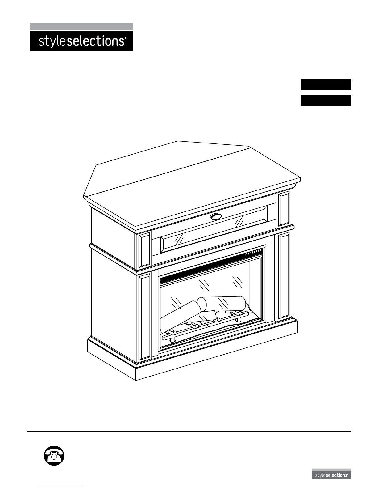
WALL/CORNER MEDIA
ELECTRIC FIREPLACE
Français p.17
Español p. 35
Style Selections® is a registered trademark
of LF, LLC. All rights reserved.
XXXXXX
Page 2
2
Lowes.com
Product Specications ......................................................................................................................... 2
Safety Information ................................................................................................................................ 3
Package Contents ................................................................................................................................ 6
Hardware Contents............................................................................................................................... 7
Preparation ........................................................................................................................................... 8
Assembly Instructions........................................................................................................................... 8
Operating Instructions ........................................................................................................................ 13
Care and Maintenance ....................................................................................................................... 13
Troubleshooting .................................................................................................................................. 14
Warranty ............................................................................................................................................. 15
Replacement Parts List ...................................................................................................................... 16
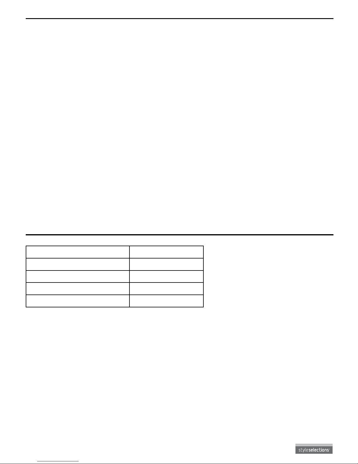
PRODUCT SPECIFICATIONS
TABLE OF CONTENTS
VOLTAGE 120 V, 60 Hz
AMPS (with heater) 11.7 Amps
AMPS (without heater) < 0.1 Amps
WATTS (with heater) 1400 Watts
WATTS (without heater) < 10 Watts
Page 3
3
Lowes.com
Please read and understand this entire manual before attempting to assemble, operate or install
the product.
WARNING
• Before assembly, carefully use scissors or utility knife to cut and unwrap all parts.
Make sure you do not discard the hardware.
CAUTION
• Use care in assembling the replace. Take your time and use the hardware provided and a quality
Phillips screwdriver. Never overtighten bolts.
• Do not sit on any part of the mantel.
• All panels are labeled left and right as viewed from the front of unit.
WARNING
To avoid injury from unexpected starting or electrical shock, do not plug the power cord into a source of
power during unpacking and assembly. The cord must remain unplugged whenever you are
adjusting/assembling the replace.
If any part is missing or damaged, do not attempt to use or plug in the power cord until the
missing or damaged part is correctly replaced. To avoid electric shock, use only identical
replacement parts when servicing double-insulated tools.
When using electrical appliances, always follow basic precautions to reduce the risk of re,
electrical shock, and injury to persons, including the following:
1. Read all instructions before using this appliance.
2. This appliance is hot when in use. To avoid burns, do not touch hot surfaces with bare skin.
If provided, use handles when moving this appliance. Keep combustible materials such as furniture,
pillows, bedding, papers, clothes and curtains at least 3 ft. from the front of this appliance.
WARNING: In order to avoid overheating, do not cover the heater.
WARNING: Use extreme caution when operating heater near children and the disabled.
3. The appliance is not to be used by children or persons with reduced physical, sensory or mental
capabilities, or lack of experience and knowledge, unless they have been given supervision
or instruction.
4. This appliance is not a toy. Supervise children playing near it.
5. If possible, always unplug this appliance when not in use.
6. Do not operate any heater with a damaged cord or plug, after the appliance malfunctions, or if it has
been dropped or damaged in any manner.
7. If the supply cord is damaged, it must be replaced by the manufacturer, its service agent or similarly
qualied persons in order to avoid a hazard.
8. Only a qualied service person should repair this product.
9. Under no circumstances should this replace be modied. Parts having to be removed for servicing
must be replaced prior to operating this replace again.
10. Do not use outdoors.
11. This heater is not intended for use in bathrooms, laundry areas and similar indoor locations. Never
locate this appliance where it may fall into a bathtub or other water container.
12. Do not run cord under carpeting. Do not cover cord with throw rugs, runners or the like. Arrange cord
away from trafc areas and where it will not be tripped over.
13. To disconnect this appliance, turn controls to the off position, and then remove plug from outlet.
14. Connect to properly grounded outlets only.
15. This appliance, when installed, must be electrically grounded in accordance with local codes or, in
the absence of local codes, with the current CSA C22.1 Canadian Electrical Code or for U.S.A.
installations, follow local codes and the National Electrical Code, ANSI/NFPA NO.70.
SAFETY INFORMATION
Page 4
4
Lowes.com
16. The heater must not be located immediately below a socket-outlet.
17. Do not insert or allow foreign objects to enter any ventilation or exhaust opening as this may cause
an electric shock or re, or damage the appliance.
18. To prevent a possible re, do not block air intakes or exhaust in any manner. Do not use on soft
surfaces, like a bed, where opening may become blocked.
19. This appliance has hot and arcing or sparking parts inside. Do not use it in areas where gasoline,
paint or ammable liquids are used or stored. This replace should not be used as a drying rack for
clothing. Do not hang Christmas stockings or other decorations on or near this product.
20. Use this appliance only as described in the manual. Any other use not recommended by the
manufacturer may cause re, electric shock or injury to persons.
21. There is a thermostat limiter inside the heater. When inner temperature overheating or abnormal
heating occurs, the thermostat protective device will cutoff the power supply to avoid damage to the
replace or risk of re.
22. Avoid the use of an extension cord because the extension cord may overheat and cause risk of re.
However, if you have to use an extension cord, the cord must be No.14 AWG minimum size and rated
not less than 1875 watts. The extension cord must be a three-wire cord with grounding type plug and
cord connection. The extension cord should not be more than 20 ft. in length.
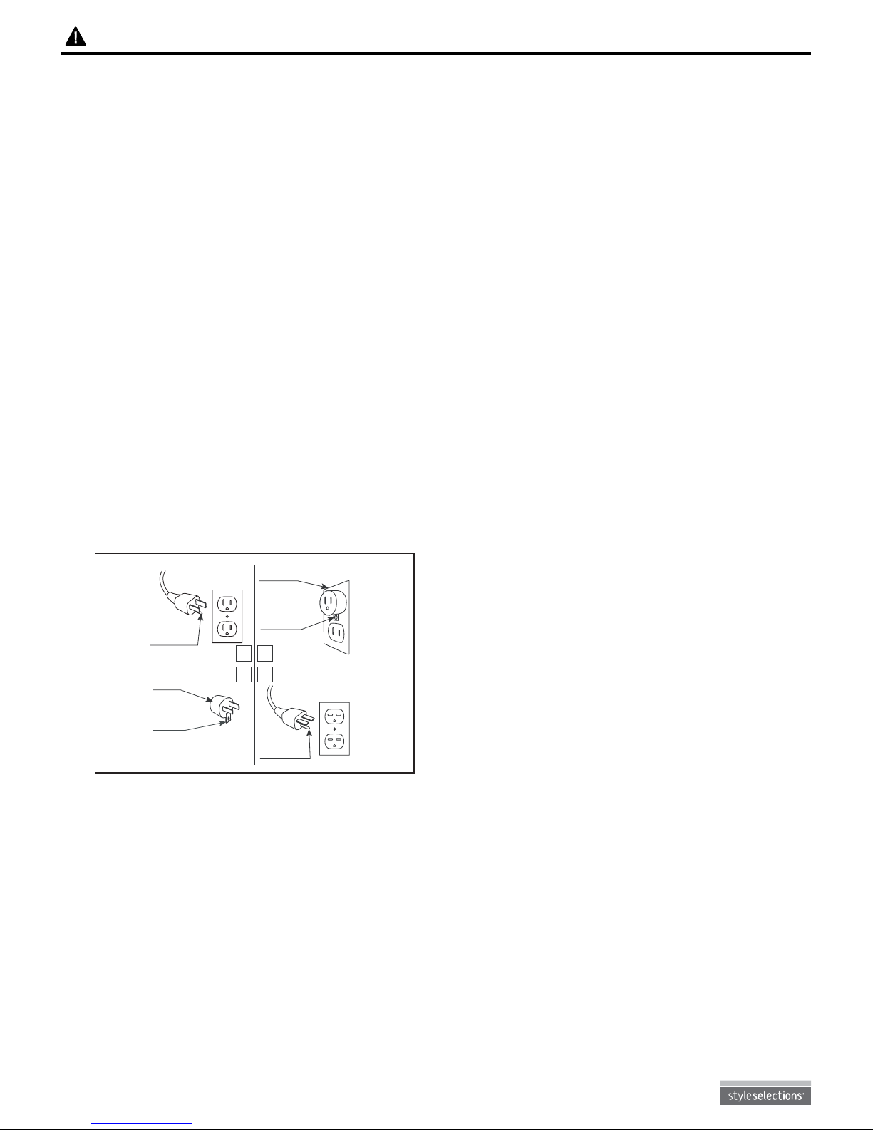
23. See directions in Figure 1. This heater is for use on 120 volts. The cord has a plug as shown in
Figure 1. See Figure 1 for grounding instruction. An adaptor as shown at C is available for connecting
three-blade grounding type plugs to two-slot receptacles. The green grounding plug extending from
the adaptor must be connected to a permanent ground such as a properly grounded outlet box. The
adaptor should not be used if a three-slot grounded receptacle is available.
B
A
C D
Grounding Pin
Fig. 1
Metal
Screws
Grounding
Means
SAVE THESE
INSTRUCTIONS
SAFETY INFORMATION
Adapter
Cover Of Grounded
Outlet Box
Grounding
Pin
Page 5
NOTE: This equipment has been tested and found to comply with the limits for a Class B digital device,
pursuant to part 15 of the FCC Rules. These limits are designed to provide reasonable protection against
harmful interference in a residential installation. This equipment generates, uses, and can radiate radio
frequency energy and, if not installed and used in accordance with the instructions, may cause harmful
interference to radio or television reception, which can be determined by turning the equipment off and
on. The user is encouraged to try to correct the interference by one or more of the following measures:
• Reorient or relocate the receiving antenna.
• Increase the separation between the equipment and the receiver.
• Plug the equipment into an outlet on a circuit different from that to which the receiver is connected.
• Consult the dealer or an experienced radio/TV technician for help.
This device complies with Part 15 of the FCC Rules. Operation is subject to the following two conditions:
(1) This device may not cause harmful interference, and
(2) this device must accept any interference received, including interference that may cause undesired
operation.
Modications not approved by the party responsible for compliance could void user’s authority to operate
the equipment.
This Class B digital apparatus complies with Canadian ICES-003.
NOTE: PLEASE OPERATE REMOTE TRANSMITTER AT A SLOW MEASURED PACE. PRESS THE
REMOTE CONTROL BUTTONS WITH AN EVEN MOTION AND GENTLE PRESSURE. REPEATEDLY
PRESSING BUTTONS IN RAPID SUCCESSION MAY CAUSE THE TRANSMITTER TO MALFUNCTION.
WARNING: Make sure the power is turned off before proceeding. Any electrical repairs
or rewiring of this unit should be carried out by a licensed electrician in accordance with
national and local codes.
If repairing or replacing any electrical component or wiring, the original wire routing,
color coding and securing locations must be followed.
WARNING: Electrical outlet wiring must comply with local building codes and other
applicable regulations to reduce the risk of re, electrical shock and injury to persons.
WARNING: Do not use this replace if any part of it has been under water. Immediately
call a qualied service technician to inspect the replace and replace any part of the
electrical system.
WARNING: Disconnect power before attempting any maintenance or cleaning to reduce
the risk of re, electrical shock or personal injury.
WARNING: During any service of this appliance, the power to the unit must be turned off.
First turn the main power switch to the OFF position, then remove the electrical plug from
the wall outlet.
SAFETY INFORMATION
5
ELECTRICAL CONNECTION
A 15-Amp, 120-volt, 60 Hz circuit with a properly grounded outlet is required. Preferably, the replace will
be on a dedicated circuit as other appliances on the same circuit may cause the circuit breaker to trip or
the fuse to blow when the heater is in operation. The unit comes standard with 6 ft. three-wire
cord, exiting from the rear of the replace. Avoid using an extension cord. If an extension cord must be
used, it must be a minimum 14 AWG, three-wire cord with grounding-type plug connector and rated not
less than 1875 watts. The cord should not be more than 20 ft. in length.
Cold climate installation recommendation: When installing this unit against a noninsulated exterior wall or chase, it is mandatory that the outer walls be insulated to
conform to applicable insulation codes.
Page 6
6
Lowes.com
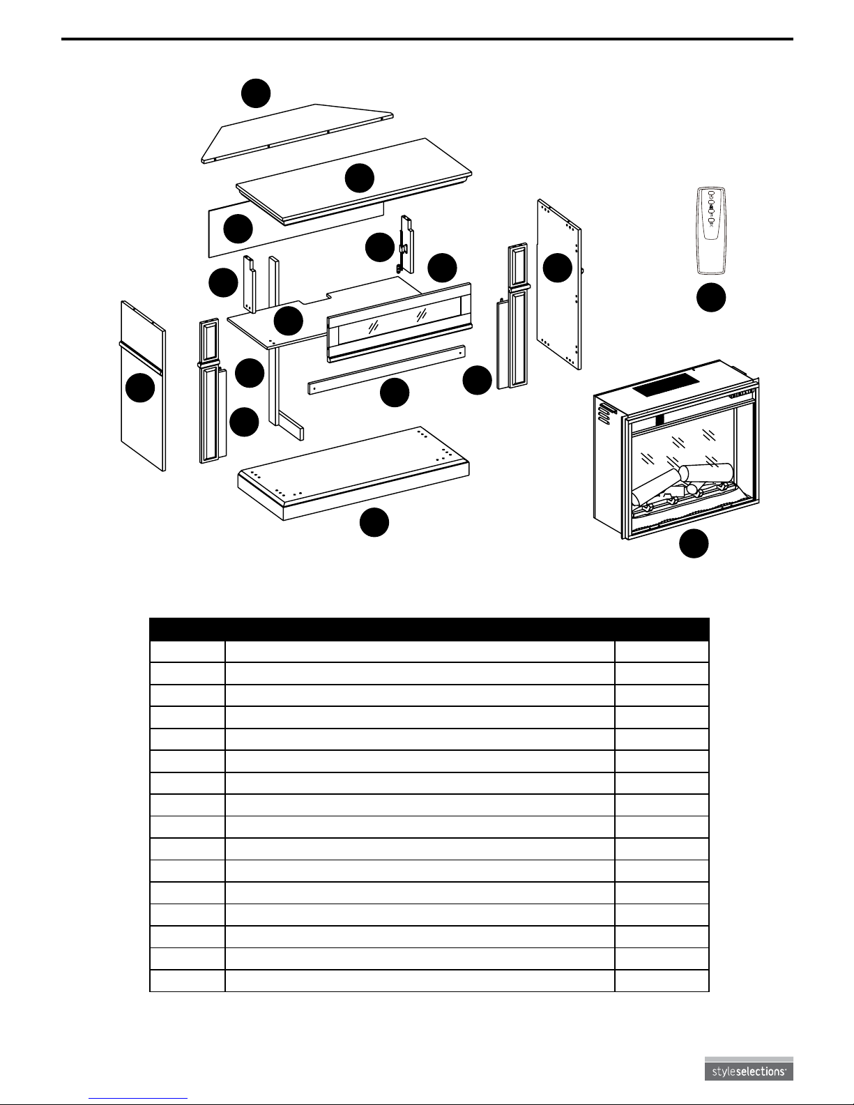
PACKAGE CONTENTS
PART DESCRIPTION QUANTITY
A Hearth/Base 1
B Left Front Panel 1
C Left Side Panel 1
D Center Front Panel 1
E Right Front Panel 1
F Right Side Panel 1
G Mantel/Top 1
H Center Shelf 1
I Back Panel 1
J Front Flip Down Door 1
K Top Corner Extension 1
L Left Support Panel 1
M Right Support Panel 1
N “L” Corner Brace 1
O Insert 1
P Remote Control 1
G
M
B
A
N
O
C
E
F
D
H
L
J
I
K
P
REMOTE/REMOTO/
TÉLÉCOMMANDE
Page 7
7
Lowes.com
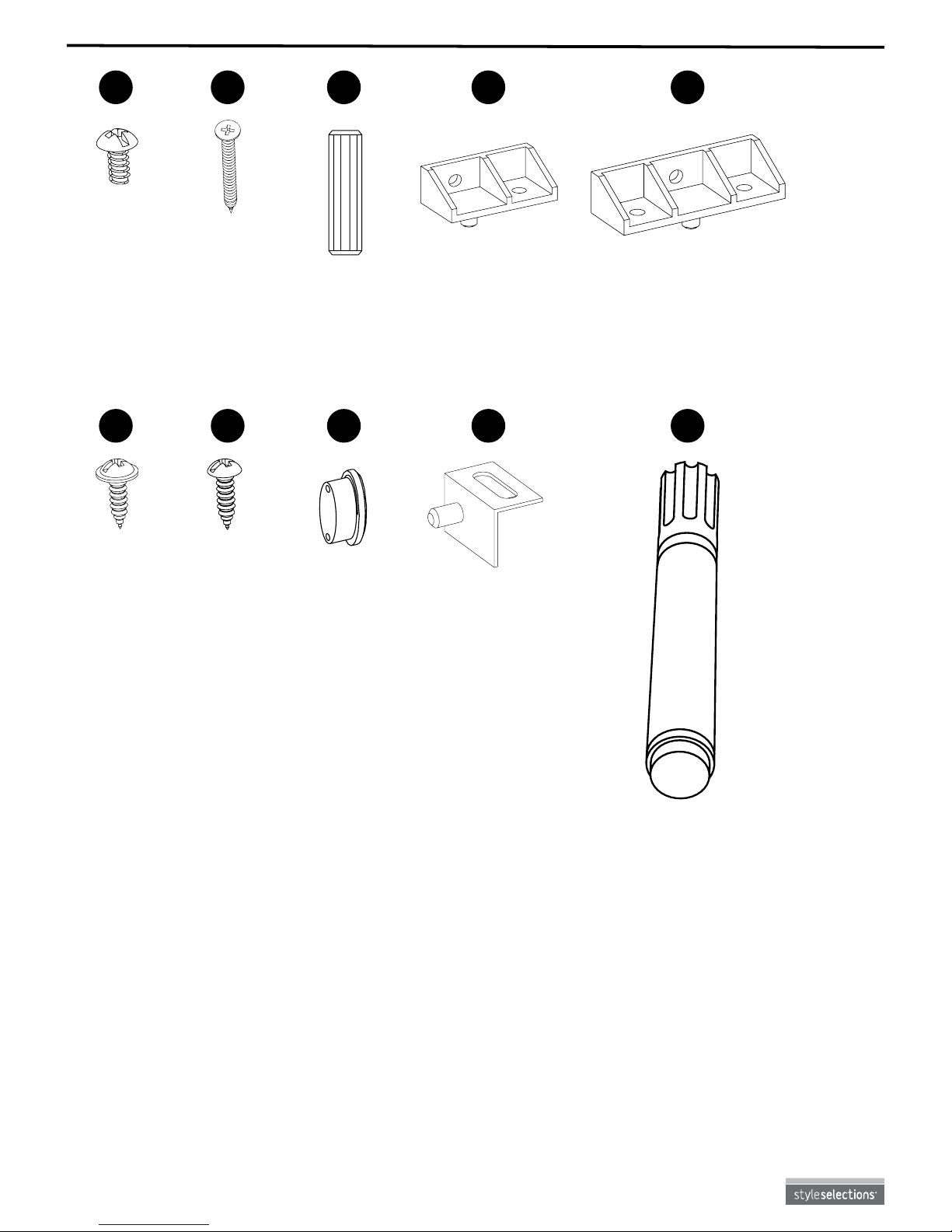
HARDWARE CONTENTS (shown actual size)
Bolt
Short Screw
Long Screw
Small Screw
Wood Dowel
Door Pull
Short Assembly
Locking Block
Hinge
Long Assembly
Locking Block
Touch-up Pen
Model No. W3348
Qty: 68
Qty: 16
Qty: 2
Qty: 2
Qty: 12
Qty: 1
Qty: 22
Qty: 2
Qty: 8
Qty: 1
AA
FF
BB
GG
CC
HH
DD
II
EE
JJ
W3348
Page 8
8
Lowes.com
ASSEMBLY INSTRUCTIONS
PREPARATION
Before beginning assembly of product, make sure all parts are present. Compare parts with package
contents list and hardware contents list. If any part is missing or damaged, do not attempt to assemble,
install or operate the product.
Estimated Assembly Time: 60 minutes
Tools Required for Assembly (not included): Phillips screwdriver, scissors and utility knife.
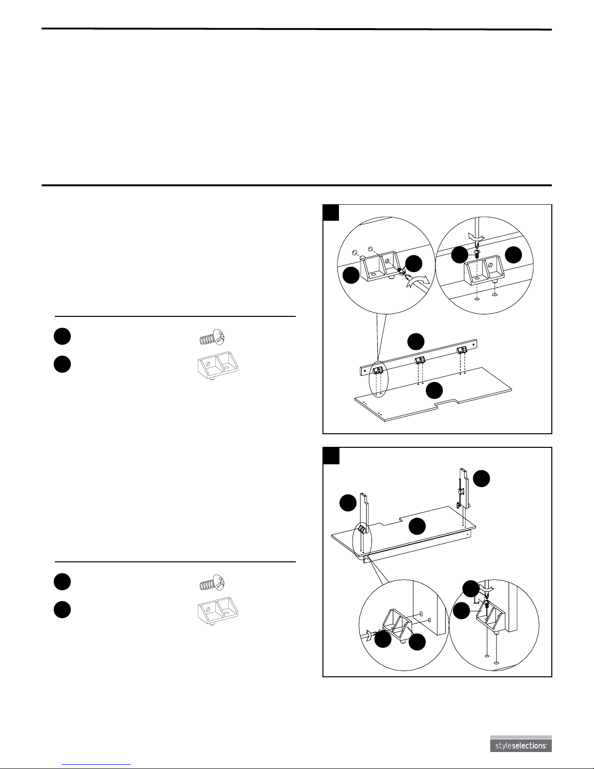
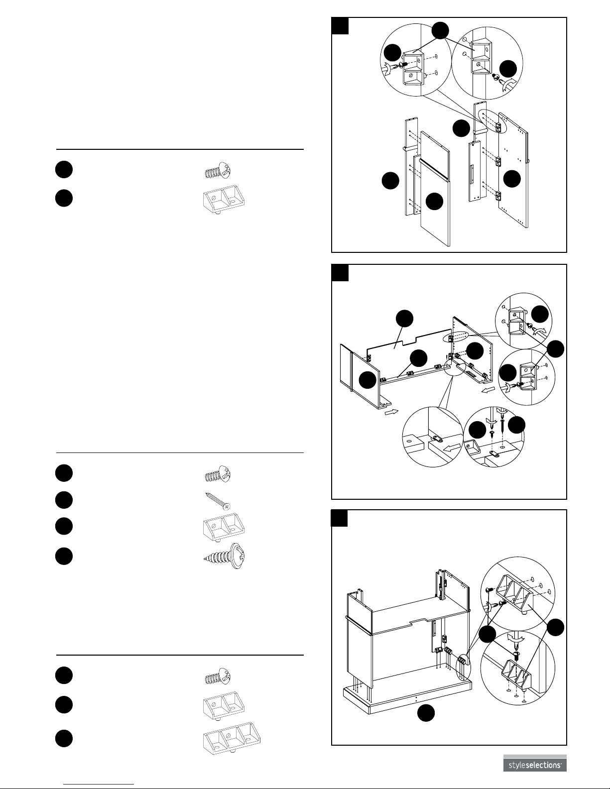
1. Set center shelf (H) and center front panel (D) face
down on a scratch-free surface. Screw the bolts
(AA) through the short assembly locking block (DD)
and into the center front panel (D). Attach the center
front panel (D) to center shelf (H) using bolts (AA)
through the holes in the short assembly locking
block (DD) and tighten.
Hardware Used
Hardware Used
DD
DD
AA
AA
Short Assembly
Locking Block
Short Assembly
Locking Block
Bolt
Bolt
x 3
x 2
x 6
x 4
H
H
DD
DD
DD
DDAA
AA
AA
AA
D
1
2. Screw the bolts (AA) through the short assembly
locking block (DD) and into the left support panel
(L). Attach the left support panel (L) to center shelf
(H) using bolts (AA) through the holes in the short
assembly locking block (DD) and tighten.
REPEAT FOR OPPOSITE SIDE.
L
M
2
Page 9
9
Lowes.com
3. Set the left front panel (B), right front panel (E), left
side panel (C), and right side panel (F) face down
on a scratch-free surface. Screw the bolts (AA)
through the short assembly locking block (DD) and
into the left side panel (C). Attach the left front
panel (B) to left side panel (C), using bolts (AA)
through the holes in the short assembly locking
block (DD) and tighten.
REPEAT FOR OPPOSITE SIDE.
4. Attach the completed assembly from step 2 to the
completed assembly from step 3. Screw the bolts
(AA) through the short assembly locking block (DD)
and into the center shelf (H). Attach center shelf
(H) to left side panel (C) and right side panel (F)
using bolts (AA) through the holes in the short
assembly locking block (DD) and tighten. Connect
the left side panel (C) and right side panel (F) to
center shelf (H) by tightening short screws (FF) into
pre-drilled holes corresponding with connection
plate on center panel (D). Further secure using long
screws (B) through the pre-drilled holes in the
center front p anel (D).
HAND TIGHTEN ONLY.
DD
BB
FF
DD
E
F
B
F
H
D
C
C
AA
AA
AA
AA
3
4
5. Place the completed assembly from step 4 on top of
the hearth/base (A). Secure with bolts (AA) through
the holes in the short assembly locking block (DD)
and the long assembly locking block (EE).
HAND TIGHTEN ONLY.
AA
A
EE
5
Hardware Used
Hardware Used
Hardware Used
DD
EE
DD
DD
FF
AA
AA
AA
BB
Short Assembly
Locking Block
Long Assembly
Locking Block
Short Assembly
Locking Block
Short Assembly
Locking Block
Short Screw
Bolt
Bolt
Bolt
Long Screw
x 6
x 4
x 4
x 2
x 2
x 12
x 16
x 8
x 2
Page 10
10
Lowes.com
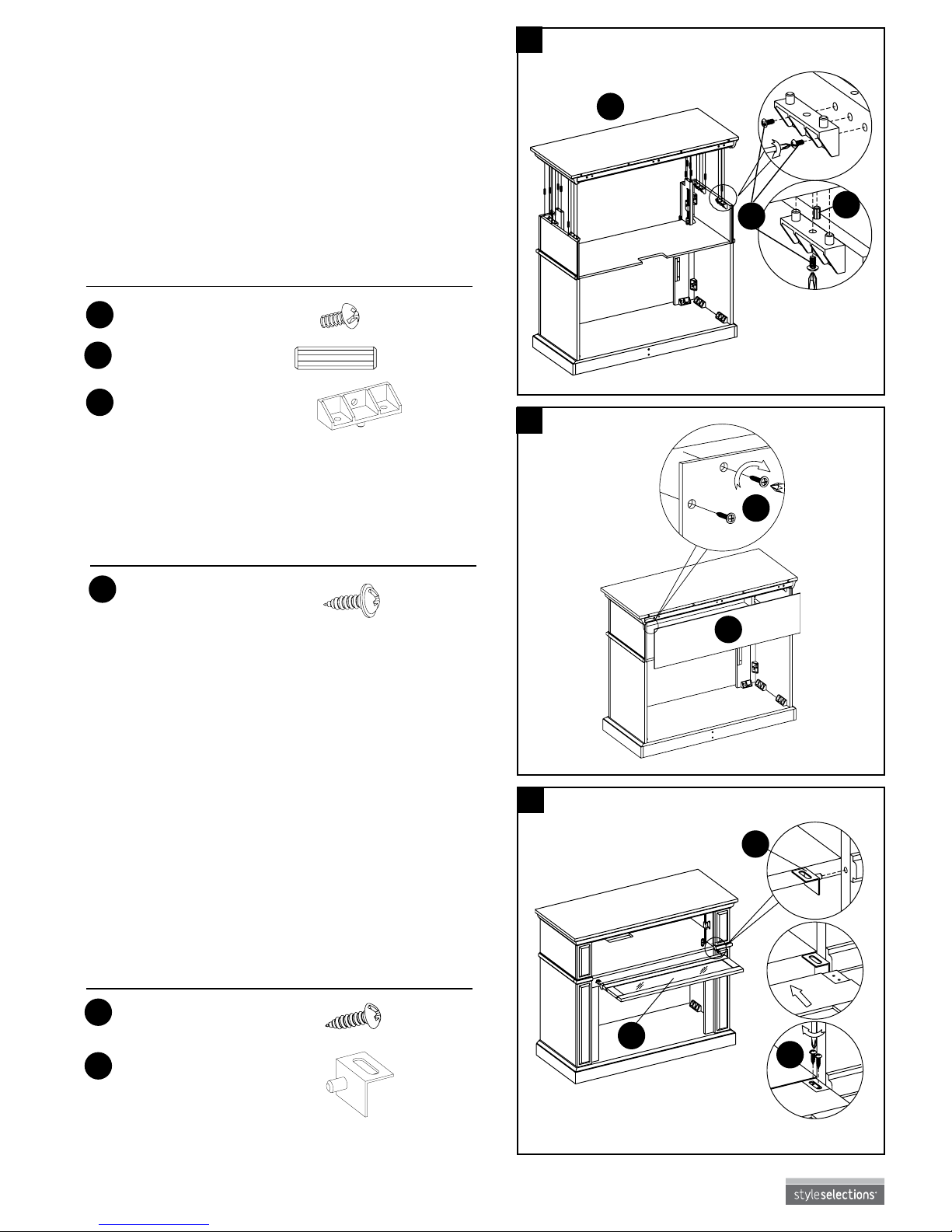
6. Insert wood dowels (CC) into each of the pre-drilled
holes on the top edges of the assembly from step 5.
Place the mantel/top (G) nished-side-up on top of
the completed assembly. From the inside, attach the
mantel/top (G) using bolts (AA) through the pre drilled holes in the long assembly locking block (EE).
HAND TIGHTEN ONLY.
Using a Phillips screwdriver (not included), tighten
all bolts (AA), alternating top and bottom, left
and right.
7. Attach back panel (I) to the back of the completed
assembly from step 6. Using a Phillips screwdriver,
tighten short screws (FF) through the pre-drilled
holes on the back panels (I).
Hardware Used
G
AA
CC
6
7
CC
Wood Dowel
x 8
AA
J
GG
Hardware Used
II
GG
Small Screw x 6
Hinge x 2
8. Insert hinge (II) into the holes of left front panel (B)
and right front panel (E). Attach front ip down door
(J) to left front panel (B) and right front panel (E)
using small screws (GG) through the holes in the
Hinge (II) and tighten.
8
spring
hinge
Hardware Used
FF
Short Screw x 14
EE
AA
Long Assembly
Locking Block
Bolt
x 4
x 12
I
FF
Page 11
11
Lowes.com
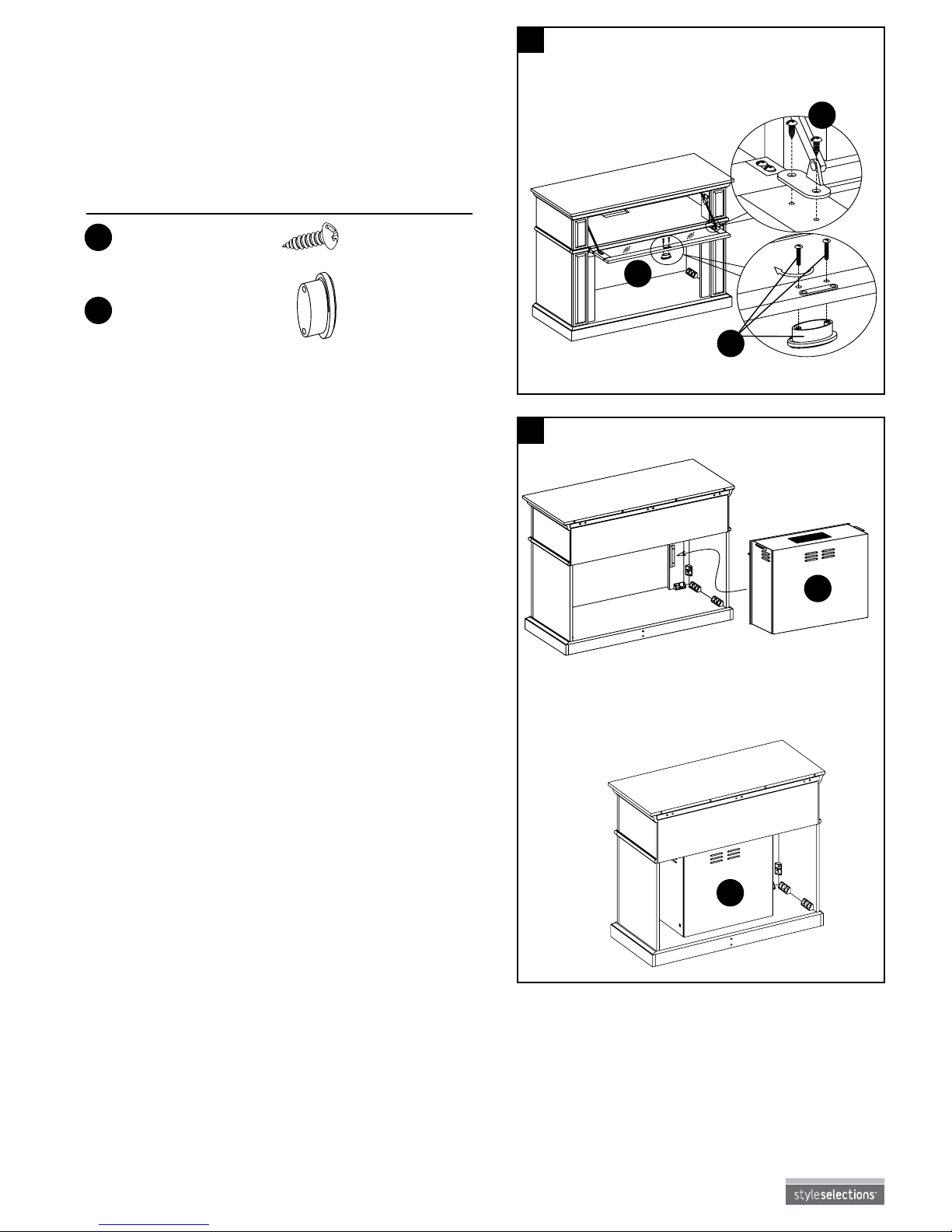
9. Stretch pre-attached piston hinge from left support
panel (L) and right support panel (M) to meet front
ip down door (J), then tighten small screws (GG)
in the pre-drilled holes. To install door pull (HH),
remove preassembled screws and then insert them
into the pre-drilled holes on the front hutch (J) and
back into door pull (HH) securely.
GG
AA
J
O
O
Hardware Used
GG
HH
Small Screw
Door Pull
x 4
x 1
9
Completed
Unit
Electric
Fireplace Insert
Install
Insert
From
Back
10. Remove the two mounting brackets attached to the
back of the front panels by removing the two screws
on each mounting bracket. Set aside. Do not install
the insert (O) until the replace mantel has been
placed close to its nal resting position. Lift insert (O)
carefully into the back of the unit and center in the
opening. Do not drag insert (O) across hearth/base
(A) as it may scratch the unit. Reinstall the mounting
brackets to hold insert (O) ush against the inside of
the mantel front panel.
NOTE: Move the completed unit only short distances.
NOTE: Move completed unit with great care.
It takes two people to move completed unit
into nal position.
10
Page 12
12
Lowes.com
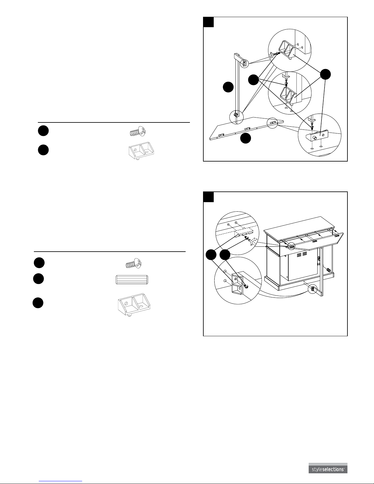
12. Insert wood dowels (CC) into each of the pre-drilled
holes the back of the mantel/top (G). Attach the
completed assembly from step 11 into place at the
back of unit, using bolts (AA) through the pre-drilled
holes in the short assembly locking block (DD)
and tighten.
DD
DD AA
K
N
AA
11. Set “L” corner brace (N) and top corner extension
(K) face down on a scratch-free surface. Attach
short assembly locking block (DD) to the top corner
extension (K) using bolts (AA) through the holes
in the short assembly locking block (DD) and
tighten. Attach short assembly locking block (DD)
to the “L” corner brace (N) using bolts (AA) through
the holes in the short assembly locking block (DD)
and tighten. Attach the “L” corner brace (N) to the
top corner extension (K) using bolts (AA) through
the holes in the short assembly locking block (DD)
and tighten.
Set part aside.
Hardware Used
11
12
EE
AA
Short Assembly
Locking Block
Bolt
x 5
x 6
Hardware Used
CC
Wood Dowel
x 4
AA
Bolt
x 4
DD
Short Assembly
Locking Block
x 4
Page 13
13
Lowes.com
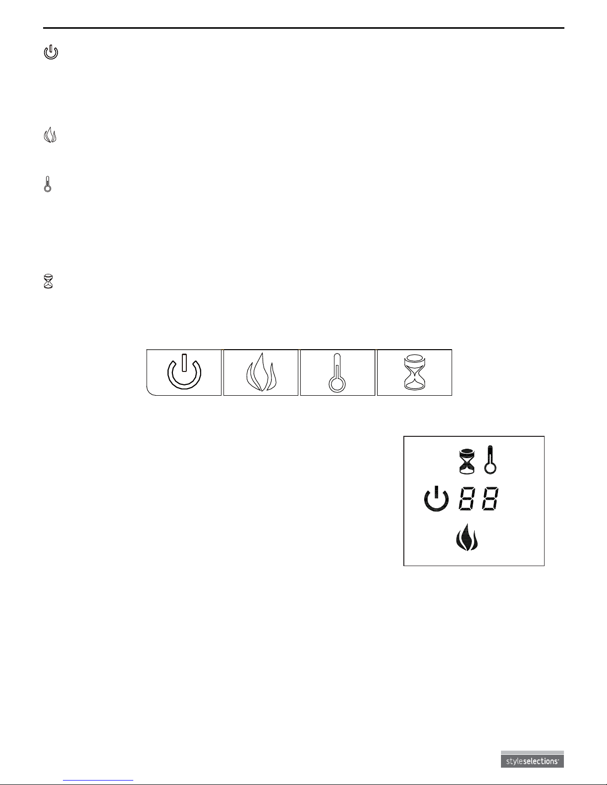
Note: When a function is changed from the control
panel or remote control there will be a corresponding
indicator (see Figure 1) on the upper-right of the
projection screen. The indicator shows the function
changed and the level selected by the control panel or
remote control. When the function is turned off, the
corresponding indicator will ash several times and then
fade off.
°
°CF
Fig . 1
OPERATING INSTRUCTIONS
Control panel can be accessed at upper-right corner of insert (O).
- POWER
The power button supplies power to all the functions of the replace. The power button will put the
replace in a standby mode. This will turn off all functions at once but will hold the settings in the memory.
By pressing the power button again the unit will turn on at the same settings.
NOTE: Holding the power button on the control panel for 10 seconds will disable the heater function.
- FLAME
Each time the ame button is pressed, the intensity of the ame decreases. There are 6 brightness levels
to cycle through, including the OFF setting.
- HEATER
The replace consists of a fan-forced wire element-type heater. The thermostat setting range is
62-82°F or always ON.
This button on the remote control only turns heater function ON and OFF.
NOTE: To change between °F and °C, press and hold the heater button on the control panel for
10 seconds.
- TIMER
Press the timer button to cycle through 10 timer settings (30 minutes, 1 hour, 2h, 3h, 4h, 5h, 6h,
7h, 8h and 9h and the OFF setting).
Page 14
14
Lowes.com
REPLACING THE REMOTE CONTROL BATTERIES
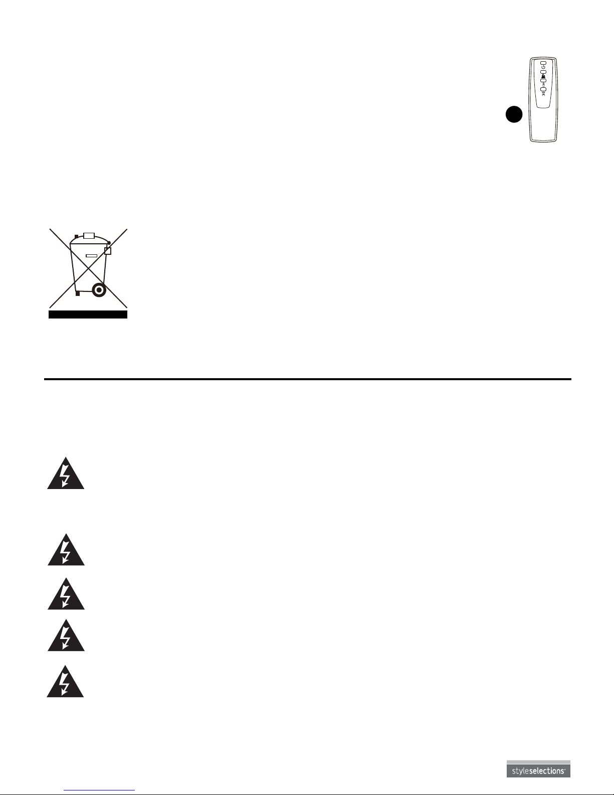
When the remote control (P) stops operating or its range seems reduced, it is time to replace the battery
with a new one. Note: Battery should be removed if the product is to be left unused for a long time.
1. The battery compartment is located on the back end of the remote control (P).
2. Press and slide the battery door open and remove the old battery.
3. Insert 2 AAA batteries, checking that the + and - sides of the battery match
inside the battery compartment.
4. Replace the battery compartment door.
Note: Do not mix old and new batteries.
Do not mix alkaline, standard (carbonzinc), or rechargeable (nicad, nimh, etc) batteries.
DISPOSAL OF USED BATTERIES
Battery may contain hazardous substances which could be endangering to
enviroment and human health.
This symbol marked on the battery and/or packaging indicates that used battery shall
not be treated as municipal waste. Instead it shall be left at the appropriate collection
point for recycling.
By ensuring the used batteries are disposed of correctly, you will help preventing
potential negative consequences for the environment and human health. The recycling
of materials will help to converse natural resources.
For more information about collection and recycling of used batteries, please contact
your local municipality, your waste disposal service or the point of sale where you
purchased this point.
CARE AND MAINTENANCE
WARNING: Make sure the power is turned off before proceeding. Any electrical repairs
or rewiring of this unit should be carried out by a licensed electrician in accordance with
national and local codes.
If repairing or replacing any electrical component or wiring, the original wire routing,
color coding and securing locations must be followed.
• The motors used on the fan and the ame generator assembly are pre-lubricated for extended
bearing life and require no further lubrication. However, periodic cleaning/vacuuming of the fan/heater
is recommended.
• Make sure the unit is turned OFF and unplugged whenever you are cleaning the heater or replace.
WARNING: Electrical outlet wiring must comply with local building codes and other
applicable regulations to reduce the risk of re, electrical shock and injury to persons.
WARNING: Do not use this replace if any part of it has been under water. Immediately
call a qualied service technician to inspect the replace and replace any part of the
electrical system.
WARNING: Disconnect power before attempting any maintenance or cleaning to reduce
the risk of re, electrical shock or personal injury.
WARNING: During any service of this appliance, the power to the unit must be turned off.
First turn the main power switch to the OFF position. Then remove the electrical plug from
the wall outlet.
P
REMOTE/REMOTO/
TÉLÉCOMMANDE
Page 15
15
Lowes.com
TROUBLESHOOTING
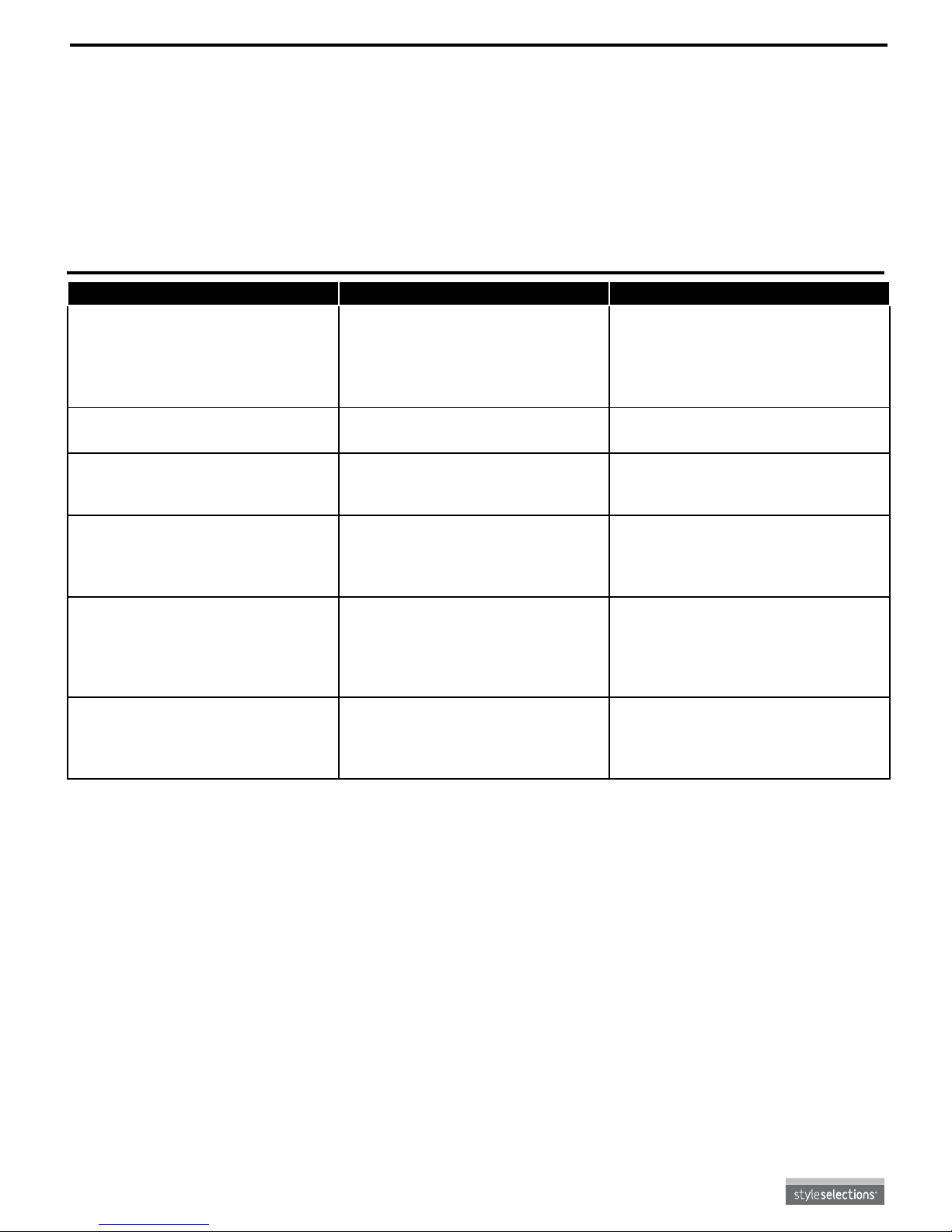
PROBLEM POSSIBLE CAUSE CORRECTIVE ACTION
No power, logs do not glow. 1. Power cord was not
plugged in the outlet.
2. Main power switch is not
in “ON” position.
1. Check that unit is plugged into
a standard 120V outlet.
2. Press power button several
times, making sure power
is set at “ON” position.
Logs glow, but no ame effect. Flame button is not in
“ON” position.
Press ame button several times.
Downlights do not light up. Downlight button is not in
“ON” position.
Try to turn on/off downlight switch
several times to make sure downlight is at “ON” position.
Heater does not blow warm air. The current room temperature
is higher than the temperature
setting.
Adjust the temperature settings
to ensure that the thermostat is
set higher than the current room
temperature.
Heater doesn’t work, but Power
and Heater settings are “ON”
and thermostat is set.
The product is on protected
status.
Turn all switches to the “OFF”
position and unplug the unit from
the wall outlet for 5 minutes. After
5 minutes plug the unit back into
wall outlet and operate as normal.
Flame effect works but heater
function does not and the
emberbed ashes when the
heater button is pressed.
Heater function is locked. Press and hold the POWER
button to unlock the heater
function.
CARE AND MAINTENANCE
• Dust your replace regularly with a soft, non-lint producing cloth or household dusting product.
• Clean your replace with a gentle non-abrasive household cleaner. Make sure to dry your replace
immediately with a soft cloth or towel.
• Tips for using touch-up pen (GG): For scratches, stroke in direction of scratch. For worn areas,
stroke in direction of wood grain. Rub excess cororant promptly with a soft cloth.
Page 16
16
Lowes.com
1-YEAR LIMITED WARRANTY
The manufacturer warrants this product to be free from manufacturing and material defects for a period of
one year from date of purchase, subject to the following conditions and limitations.
1. Install and operate this item in accordance with the installation and operating
instructions furnished with the product at all times. Any unauthorized repair, alteration, willful abuse,
accident, or misuse of the product shall nullify this warranty.
2. This warranty is non-transferable, and is made to the original owner, provided that the purchase was
made through an authorized supplier of the product.
3. The warranty is limited to the repair or replacement of part(s) found to be defective in material or
workmanship, provided that such part(s) have been subjected to normal conditions of use and
service, after said defect is conrmed by the manufacturer’s inspection.
4. The manufacturer may, at its discretion, fully discharge all obligations with respect to this warranty by
refunding the wholesale price of the defective part(s).
5. Any installation, labor, construction, transportation, or other related costs/expenses arising from
defective part(s), repair, replacement, or otherwise of same, will not be covered by this warranty,
nor shall the manufacturer assume responsibility for same.
6. The owner/user assumes all other risks, if any, including the risk of any direct, indirect or
consequential loss or damage arising out of the use, or inability to use the product, except
as provided by law.
7. All other warranties – expressed or implied – with respect to the product, its components and
accessories, or any obligations/liabilities on the part of the manufacturer are hereby expressly
excluded.
8. The manufacturer neither assumes, nor authorizes any third party to assume on its behalf, any other
liabilities with respect to the sale of the product.
9. The warranties as outlined within this document do not apply to non accessories used in conjunction
with the installation of this product.
10. This warranty gives you specic legal rights, and you may also have other rights which vary from
state to state.
This warranty is void if:
a. The replace is subjected to prolonged periods of dampness or condensation.
b. Any unauthorized alteration, willful abuse, accident, or misuse of the product.
c. You do not have the original receipt of purchase.
IF WARRANTY SERVICE IS NEEDED
Contact the manufacturer by calling the customer service department at 1-877-888-8225, 8 a.m. - 8 p.m.,
EST, Monday - Friday. Make sure to have the warranty, sales receipt, location of purchase and the model
serial number of the product.
Page 17
17
Lowes.com
Printed in China
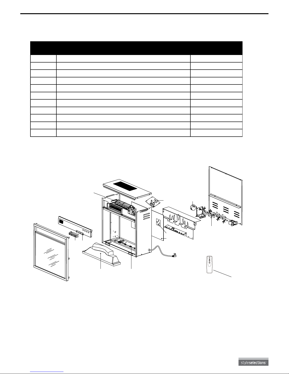
REPLACEMENT PARTS LIST
For replacement parts, call our customer service department at 1-877-888-8225, 8 a.m. - 8 p.m., EST,
Monday - Friday.
PART DESCRIPTION PART NO.
26EF023GRA
1 Heater/Blower Assembly Y07-C26-P01
2 Main Circuit Board Y11-S70-P15
3 Flame Generator Drive Motor Y07-P10Q
4 Flame Generator/Spinner Y10-S53-P011
5 LCD Display Y10-C43-P70
6 Front Projection Screen Y10-S53-P09
7 Flame Circuit Board Y11-S70-P40
8 Emberbed with Log Y10-S53-P02
9 Control Panel Circuit Board Y10-S53-P32
10 Control Panel - 4 Buttons Y10-C43-P25
11 Remote Control - 4 Buttons P71
REMOTE/REMOTO/
TÉLÉCOMMANDE
1
11
2
3
4
5
6
7
8
9
10
Style Selections® is a registered trademark
of LF, LLC. All rights reserved.
 Loading...