

DCX.Server/DCX.Client/DCX.NC
www.stute-engineering.de
Chapter
: Introduction
1
ID EN5218A DCX-SCN
EN
DCX.SERVER/DCX.CLIENT/DCX.NC

DCX.Server/DCX.Client/DCX.NC
www.stute-engineering.de
Chapter
: Introduction
2
1 Introduction .......................................................................................................................................... 4
1.1 Main function ............................................................................................................................... 4
1.2 How does it work? ....................................................................................................................... 4
1.3 Is it possible to control the DCX2496 via Wi-Fi ........................................................................ 4
1.4 Which platform is supported? .................................................................................................. 4
1.5 Is it possible to copy the DCX2496 settings for X-Over, EQ, Dyn EQ… to another
DCX2496 device? .................................................................................................................................... 5
1.6 What do I need? ......................................................................................................................... 5
1.7 Is it possible to control the DCX2496 without a separate computer? .............................. 5
1.8 Which DCX2496 functionalities are supported? ................................................................... 5
1.9 Is it possible to store/re-store the DCX2496 settings? ........................................................... 5
1.10 Can I use the DCX.Client on multiple devices (e.g. computer and tablet)? ................. 5
1.11 Is it possible to execute the DCX.Server on a Wi-Fi connected computer? ................... 5
2 Quick Start ............................................................................................................................................ 6
2.1 Note “Demo/Test Mode” .......................................................................................................... 6
2.2 Software installation ................................................................................................................... 6
2.2.1 DCX.Server (full version and trail) ......................................................................................... 6
2.2.2 DCX.Client ................................................................................................................................ 6
2.3 Program screens.......................................................................................................................... 7
2.4 Prepare your DCX2496 device ................................................................................................. 7
2.5 Firewall/network communication ............................................................................................ 7
2.6 BASIC configuration (DCX.Server & DCX.Client) .................................................................. 8
2.6.1 First steps ................................................................................................................................... 8
2.6.2 Control your DCX2496 device .............................................................................................. 8
2.7 PROFESSIONAL configuration (DCX.NC & DCX.Client) ........................................................ 9
2.7.1 First steps ................................................................................................................................... 9
2.7.2 Control your DCX2496 device .............................................................................................. 9
3 Software description ......................................................................................................................... 10
3.1 DCX.Server .................................................................................................................................. 10
3.2 DCX.Client .................................................................................................................................. 11
3.2.1 Tab “Home” ........................................................................................................................... 12
3.2.2 Tab “A B C Sum” ................................................................................................................... 13
3.2.3 Tab “EQ/Dyn EQ” .................................................................................................................. 14
3.2.4 Tab “X-Over” .......................................................................................................................... 15
3.2.5 Tab “Limiter/Phase” .............................................................................................................. 16

DCX.Server/DCX.Client/DCX.NC
www.stute-engineering.de
Chapter
: Introduction
3
3.2.6 Tab “Settings” ........................................................................................................................ 17
3.2.7 Undo-Redo Function ............................................................................................................ 21
4 Control a single or multiple DCX2496 devices ............................................................................. 22
4.1 Control a single DCX2496 device .......................................................................................... 22
4.2 Control two DCX2496 devices................................................................................................ 22
4.3 Control more than two DCX2496 devices ........................................................................... 23
5 DCX.NC controller ............................................................................................................................. 24
5.1 Connectors ................................................................................................................................. 24
5.2 LAN connection ........................................................................................................................ 24
5.3 Software update controller DCX.NC .................................................................................... 25
6 Software license key (DCX.Server) ................................................................................................. 25
7 FAQ ...................................................................................................................................................... 26
7.1 DCX.Server .................................................................................................................................. 26
7.2 DCX.Client .................................................................................................................................. 26
7.2.1 Messages (footer) ................................................................................................................. 26
7.2.2 DCX2496 values: Gain, threshold, frequency,… ............................................................. 27
7.2.3 Network / App ....................................................................................................................... 27
7.2.4 With DCX.NC controller ....................................................................................................... 28
7.3 DCX.NC ....................................................................................................................................... 28
7.3.1 Power supply .......................................................................................................................... 28
7.3.2 Network ................................................................................................................................... 28
8 System requirements ......................................................................................................................... 29
8.1 DCX.Server software ................................................................................................................. 29
8.2 DCX.Client software ................................................................................................................. 29
8.2.1 MS-Windows (PC) .................................................................................................................. 29
8.2.2 macOS .................................................................................................................................... 29
8.2.3 Android ................................................................................................................................... 29
8.2.4 iOS ............................................................................................................................................ 29
8.3 DCX.NC ....................................................................................................................................... 29
8.4 USB-RS232 interface requirements ......................................................................................... 29
DCX.Server/DCX.Client/DCX.NC
www.stute-engineering.de
Chapter
: Introduction
4
1 Introduction
Note: This manual describes the functionalities of the DCX.Server Version V1.1.x and
DCX.Client V1.1.x and above.
New in this version:
Undo/Redo function of the last action
Adjustment of the signal sources for the outputs
Adjustment of the “Out Configuration”, “In Stereo Link” and “Sum In Select”
Remote access support for stute.x1D to the DCX.Client (future use, only MS-Windows
DCX.Client)
Modified GUI style
1.1 Main function
The DCX software allows an easy remote control of your Behringer Ultradrive Pro DCX2496
loudspeaker management system from your hearing position via your local network and your
mobile phone, tablet computer or PC.
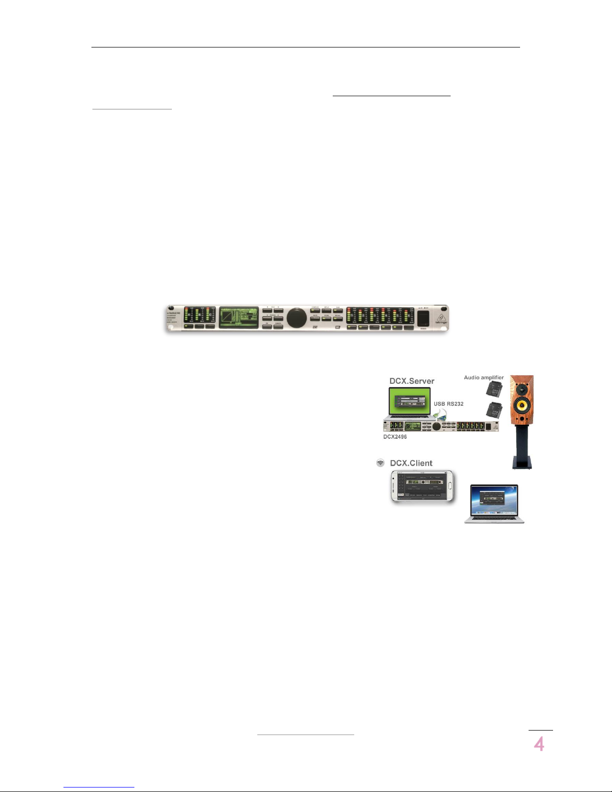
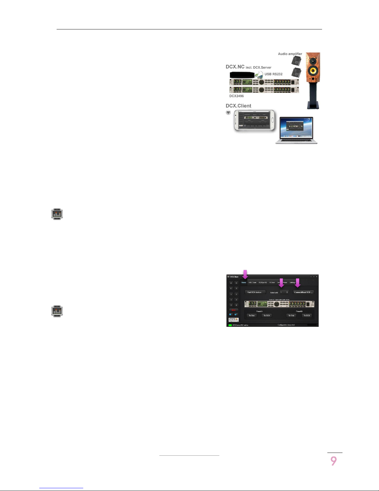
1.2 How does it work?
The system contains two software products. The DCX.Client
software provides the user interface for DCX2496 remote
control, like gain volume slider or mute switches. The client
will be installed at your mobile phone, tablet or laptop.
The DCX.Server software is installed at a second PC and
receives via Wi-Fi the DCX.Client commands. The
commands are translated and via a USB-RS232 interface to
the DCX2496 device transmitted.
Tipp: With the usage of the DCX.NC controller the second
PC omitted.
1.3 Is it possible to control the DCX2496 via Wi-Fi
Yes, the DCX.Client software can be executed on a tablet computer, mobile phone or
laptop with a wireless network connection.
1.4 Which platform is supported?
The DCX.Client is available for MS-Windows (PC), macOS, iOS and Android devices.
The DCX.Server needs a MS-Windows computer. Alternative is a stand-alone controller
available (DCX.NC).

DCX.Server/DCX.Client/DCX.NC
www.stute-engineering.de
Chapter
: Introduction
5
1.5 Is it possible to copy the DCX2496 settings for X-Over, EQ, Dyn EQ…
to another DCX2496 device?
Yes. Read the settings from the source device and store the settings in a preset. Connect the
target DCX2496 and copy the preset data to the 2nd device.
1.6 What do I need?
The DCX.Client software can be installed on your Desktop PC, Laptop, Tablet or Mobile Phone.
For the DCX.Server software you need a MS-Windows PC (Desktop, Tablet, Mini PC…) and a
USB-RS232 interface to control DCX2496 device(s).
1.7 Is it possible to control the DCX2496 without a separate computer?
Yes, with the DCX.NC controller. You need only a device like a Tablet or Mobile Phone for the
DCX.Client software.
1.8 Which DCX2496 functionalities are supported?
Input A/B/C/Sum:
o Level, Mute, Delay,
o EQ 1..9, Dynamic EQ,
o Sum Level from In A/B/C
Output 1..6:
o Level, Mute, Delay (long & short),
o EQ 1..9, Dynamic EQ,
o X-Over incl. X-Over link, Phase, Polarity, Limiter
DCX2496 Setup
o Adjustment “Out configuration” (MONO, LMH LMH,..)
o Adjustment “In Stereo Link” (A+B…)
o Adjustment Sum signal setup (A+B, A, B, C, …)
o Adjustment Output source for Out 1..6 (A,B,C, Sum)
Note: “Delay Link” is not supported and should be switched off.
1.9 Is it possible to store/re-store the DCX2496 settings?
Yes, the DCX.Client provides 2 preset memories. You can switch between the settings for a
DCX2496 unit or transfer the settings to another DCX2496 unit.
1.10 Can I use the DCX.Client on multiple devices (e.g. computer and
tablet)?
Yes. But you should avoid parallel controlling from two or more clients to the same
DCX.Server.
1.11 Is it possible to execute the DCX.Server on a
Wi-Fi connected computer?
No, the DCX.Server software has to be executed on a computer
with a wired LAN connection. But a connection via powerline
network adapter or network switch is sufficient. The DCX.Client can
be executed on a Wi-FI or LAN wired computer.
DCX.Server/DCX.Client/DCX.NC
www.stute-engineering.de
Chapter
: Quick Start
6
2 Quick Start
2.1 Note “Demo/Test Mode”
You get the full version of the DCX.Client for free.
Choose a DCX.Client from the Apple or Google store or
download the MS-Windows or macOS client version
from our download page.
The DCX.Server software is available from our download page as a test version with a limited
functionality. Download and install the DCX.Server on a MS-Windows PC. In the demo version
you can only control the gain & mute of the DCX2496 inputs A, B and C.
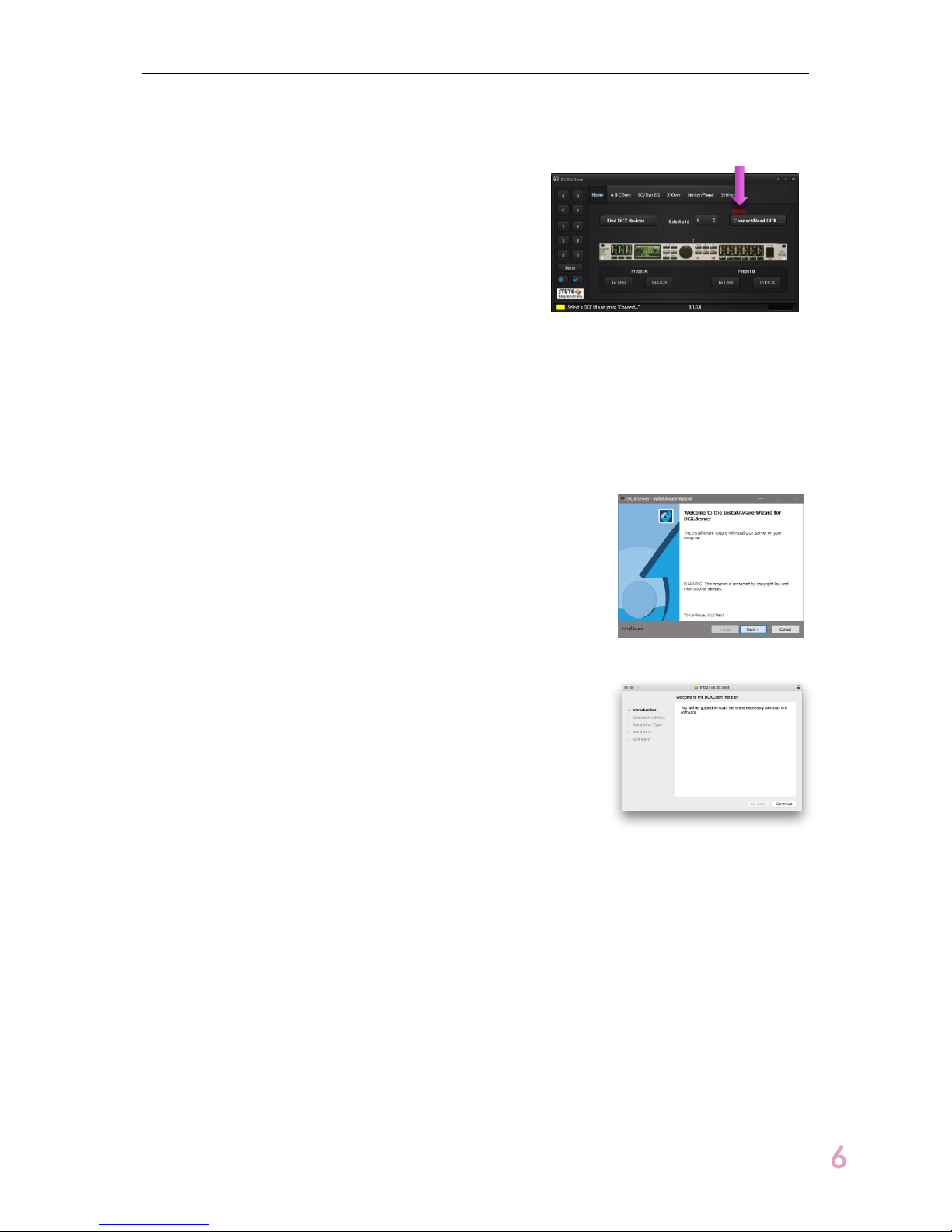
2.2 Software installation
2.2.1 DCX.Server (full version and trail)
Download the setup file from out homepage (see “Download”).
Open the setup file to start the installation. Follow the displayed
messages from the setup screen.
2.2.2 DCX.Client
2.2.2.1 macOS
Download the setup file (PKG) from out homepage (see
“Download”). Open the “DCXClient.PKG” package file to start
the installation. Follow the displayed messages from the setup
screen.
Note: Enable System Preferences / Security & Privacy / Allow
apps download from “Mac App Store and identified developers”
2.2.2.2 MS-Windows
Download the setup file from out homepage (see “Download”). Open the setup file to start
the installation. Follow the displayed messages from the setup screen (similar to the
DCX.Server installation).
2.2.2.3 Android
Install the app via the Google Play store. Search for “DCX.Client”.
2.2.2.4 iOS
Install the app via the iTunes App store. Search for “DCX.Client”.
DCX.Server/DCX.Client/DCX.NC
www.stute-engineering.de
Chapter
: Quick Start
7
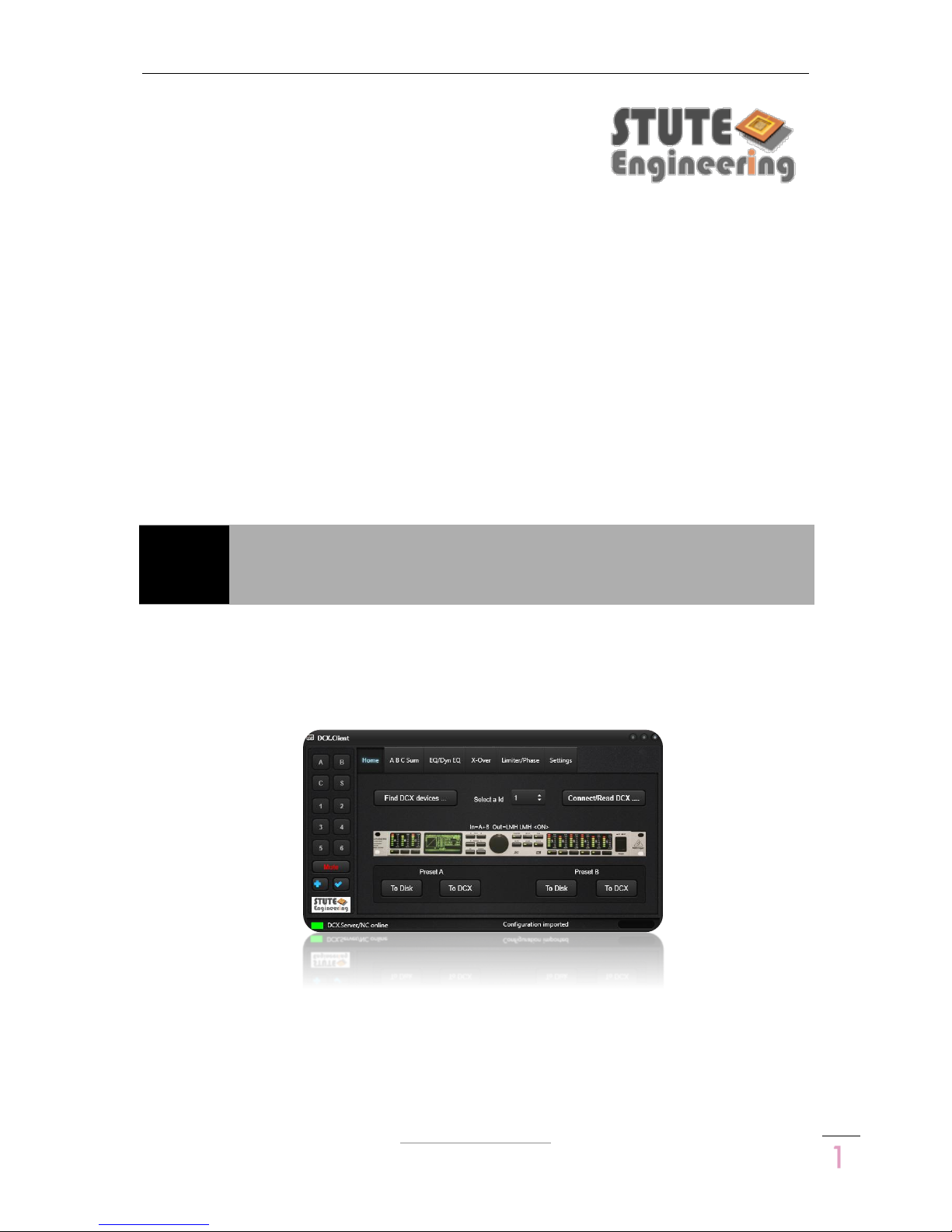
2.3 Program screens
DCX.Server DCX.Client
Note: Few details of the screens for iOS, Android, macOS and MS-Windows can be different.
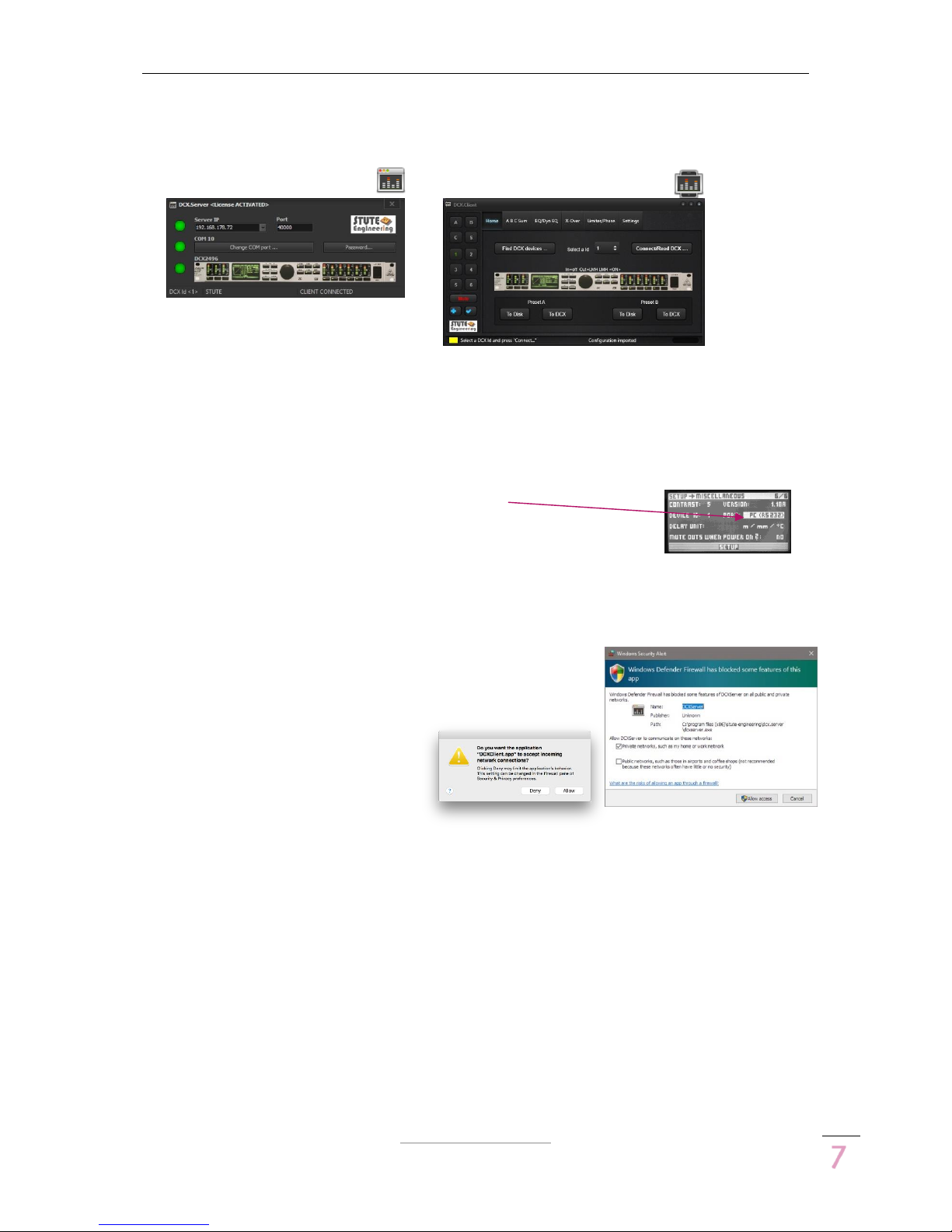
2.4 Prepare your DCX2496 device
Press the “SETUP” button from the DCX2496 device
Choose the page “SETUP Miscellaneous”
o Select “Port” and set “PC (RS232)” via the DCX2496 data
wheel to control a single DCX2496 device
o Settings for a DCX2496 device cluster see chapter 4
Press the “SETUP” button to store the changes
2.5 Firewall/network communication
Important: Allow the network communication between the
software DCX.Server and DCX.Client via your firewall.
During the operation the firewall recognize the new network
traffic and ask how to proceed. For a
proper work allow the software
communication.

DCX.Server/DCX.Client/DCX.NC
www.stute-engineering.de
Chapter
: Quick Start
8
2.6 BASIC configuration (DCX.Server &
DCX.Client)
2.6.1 First steps
DCX.Server software
Install the DCX.Server software at your MS-
Windows computer (see chapter 2.2)
Connect a USB-RS232 interface (38400 baud)
to your computer and the Behringer DCX2496
device
Switch on your DCX2496 device
Open the DCX.Server program
o Press the button “Change COM port…”.
o Select a COM port and press “OK”. The COM led shines green
Check the displayed “Server IP” address
o Is it a valid IP of your local network?
o E.g. 192.168.178.23
DCX.Client software
Note: First enable Wi-Fi or cable network connection at your device!
Install the DCX.Client software at your computer or tablet/mobile phone (see chapter
2.2)
Open the program DCX.Client (DCX.Server should already started)
o For the first start wait 20-30 seconds. The client searches for the DCX.Server
Note: Via the button “Find DCX.Server/NC” from the “Settings/Network” tab you check the
network connection to the DCX.Server.
2.6.2 Control your DCX2496 device
Follow the chapter “First steps”
Switch on your DCX2496 device
Open the DCX.Server software
Open the DCX.Client software
o “Home” tab: Select the device ID of your DCX2496 (default= 1)
Alternative press “Find DCX devices…” to scan for DCX2496 devices
o Press the button “Connect/Read DCX…” to connect the client with a DCX2496
The progress bar in footer displays the status of the DCX data import
o The software is ready to control the DCX2496
E.g., select the tab “A B C Sum”. Change the dB gain of “In A”
Check the level at the Behringer DCX2496
DCX.Server/DCX.Client/DCX.NC
www.stute-engineering.de
Chapter
: Quick Start
9
2.7 PROFESSIONAL configuration (DCX.NC
& DCX.Client)
2.7.1 First steps
DCX.NC controller
Connect the delivered power adapter with the
DCX.NC unit
Connect the DCX.NC controller with a LAN
cable to your local network (e.g. with your AVM
Fritzbox)
Connect the delivered USB-RS232 interface to a
USB port of the DCX.NC unit
o Connect the USB-RS232 interface with your DCX2496 unit
Switch on the DCX.NC controller. Wait approx. 50 seconds.
DCX.Client software
Note: First enable the Wi-Fi or cable network connection at your device!
Install the DCX.Client software at your computer or tablet/mobile phone (see chapter
2.2)
Open the program DCX.Client
o For the first start wait 20-30 seconds. The client searches for the DCX.NC
Note: Test the network connection to the DCX.NC server via the button “Check DCX.Server”
from the tab “Settings”.
2.7.2 Control your DCX2496 device
Pre-condition: DCX2496 device and DCX.NC controller
are switched on.
Open the DCX.Client (e.g. from your mobile
phone)
o Select the device ID of your DCX2496
(default= 1) from the “Home” tab
Alternative press the button “Find DCX devices…” to scan for devices.
Select afterwards a ID from the list
o Press the button “Connect/Read DCX…” to connect the client with the
DCX2496 device
The progress bar in footer displays the status of the DCX data import
o The software is ready to control the DCX2496
E.g., select the tab “A B C Sum”
Change the dB gain of “In A”
Check the level at the Behringer DCX2496

DCX.Server/DCX.Client/DCX.NC
www.stute-engineering.de
Chapter
: Software description
1
0
3 Software description
3.1 DCX.Server
Note: To use the software without the DEMO limits your DCX.Server software license must
activated. You find more details t the topic in chapter 6.
Attention: Do not connect or disconnect the USB-RS232 interface when the DCX.Server is
running
Attention: Do not quit the DCX.Server software or switch off the DCX.Server computer during
an established connection to the DCX.Client!
1
LED Network connection status
Green: Connected to the DCX.Client
Yellow: Not connected to the client
Red: Network issues
6
RS232 Port: Press the button, to select
the RS232/COM port for the USB-RS232
interface. The current port number is
displayed above of the button
2
LED RS232 interface status
Green: Displayed RS232 port (e.g.
COM10) successful opened
Yellow: Searching DCX2496 devices
Red: Displayed COM port not found or
in use via another software
7
Password protection for the settings:
Server IP, Port and COM port. Set the
password and re-start DCX.Server.
Reset the password via a two times
“blank” input.
3
LED DCX2496 communication status
Green: Successfully connected with the
DCX2496 device
Red: DCX currently not connected
/DCX powered off.
8
DCX2496 Device Id: DCX.Server is
currently connected to the displayed
DCX device Id
4
Server IP address
Must be a valid address of your local
network. Otherwise select the correct
one from the list
9
Name of the DCX.Client: Connected
currently with the displayed DCX.Client
name (name from the client software
“Settings” and “User name”)
5
Port number. Default 40000. Must be
identical to the port from the client
software
10
Status messages: Notifications and
error messages
11
Quit the program
Note: The LED “Network” and “RS232” flashes during the communication.

DCX.Server/DCX.Client/DCX.NC
www.stute-engineering.de
Chapter
: Software description
1
1
3.2 DCX.Client
General overview
1
Tab’s for the different DCX functions
- Home: Initiate the connection to a
DCX2496 plus 2 DCX presets
- Settings: Program settings
- A B C Sum… Limiter/Phase: DCX2496
controls
2
Controls/inputs to the selected tab
3
Channel selection
- A B C: Input A B C
- S: Sum
- 1..6: Outputs 1 to 6
- Mute: Mute/un-mute all outputs
- : Store last action / Undo & Redo
(see chapter 3.2.7)
Note: Depending at the selected tab
all or some buttons are disabled.
4
Footer status bar for notifications plus a
color coded status panel:
Green: Notes, no issues
Yellow: Action needed
Red: Issue, read the displayed
message
5
Footer status bar: Displays for the
selected output (star 3) the input
source and output name
6
Progress bar. Display the status for
a) The import of the DCX2496
settings after pressing the
“Connect/Read DCX” button
or
b) transmit a preset to the DCX
device after a click of the “To
DCX” preset button
7
Click at the image opens the web PDF
manual (DCX.Server & DCX.Client &
DCX.NC)
Note: A PDF viewer is needed at the
computer/tablet/mobile phone

DCX.Server/DCX.Client/DCX.NC
www.stute-engineering.de
Chapter
: Software description
1
2
3.2.1 Tab “Home”
Establish the connection to the DCX2496 device plus 2 DCX presets
1
“Find DCX devices…”
Press the button to start the scan for
connected DCX2496 devices. The
function scans the DCX device Id’s
from 1..16. The result is entered into the
device Id list (star 2).
Note: The scan takes approx. 30
seconds. After the scan the footer
shows how many devices are found
2
DCX2496 Id list. Select a valid Id and
press “Connect/Read DCX…” to
control the DCX2496 with the selected
Id.
Note: The last Id is stored
Note: After a device scan the list
includes only the existing Id’s
3
Connect/Read DCX…
Establish the connection to the
DCX2496 device with the selected Id
and import the DCX2496 settings (Gain,
EQ, X-Over…).
Note: The progress bar in the footer
displays the progress.
4
DCX2496 input and output
configuration. On: Output
configuration enabled. Off: Disabled
Note: Changes are affected a
channel combination. With
In=A+B+C+Sum, a change of the
volume “In A” level changes also the
In B, C and Sum gain. You find more
details in the DCX2496 manual.
5
2 DCX Presets to store/re-store your
preferred DCX2496 settings
Press “To Disk” to save the current
settings on your client computer
Press “To DCX” to transmit the stored
setting to the DCX2496 device
Note: The settings are stored on the
used device (e.g. computer or tablet)
Note: A confirmation screen is not
displayed with the iOS & Android apps.
Note: The software switch automatically to the “Home” tab until the data is read from the
DCX2496.

DCX.Server/DCX.Client/DCX.NC
www.stute-engineering.de
Chapter
: Software description
1
3
3.2.2 Tab “A B C Sum”
Control the DCX2496 input level, mute and delay settings.
1
Gain for input A, B, C. To change the
level
a) move the slider or
b) press the “+” or “-“ button or
c) click at the beginning or end of
the slider line to move the slider
Note: The gain step rate (0.1dB, 0.5dB
or 1dB) is defined in the program
“Settings”
Note: Depending at the Input
configuration (DCX2496 setup, see tab
“home” In=xxx) a change of single
channel adjusts other inputs
synchronously
2/3
Input “Sum B+C”
Control the “Sum” output and inputs
gain (see note). Change the gain
similar as described in “star 1”
If the viewed channel from “star 3” is:
a) Out: You control the “Sum”
output gain with the slider
b) In A or B or C: You control the
Input gain of In A or B or C of
the “Sum” signal
Note: The “Sum” channel includes the
signal from the displayed inputs, in the
picture above “B+C” (combination
configured in the DCX2496 device)
4/5
Delay view
Off position (left): Control the volume
level for Input A, B, C and “Sum” The
switch mute/un-mute a input (Sum is
disabled)
On position (right): Control the delay
for the inputs and “Sum” signal. The
switch enable or disable the delay
function

DCX.Server/DCX.Client/DCX.NC
www.stute-engineering.de
Chapter
: Software description
1
4
3.2.3 Tab “EQ/Dyn EQ”
Control the 9 channel equalizer and dynamic equalizer for the inputs and outputs.
Note: You find the details to the described DCX2496 device functions in the device manual.
1
Select a DCX2496 channel.
A,B,C: Input A,B,C
S: “Sum” channel
1..6: Output 1..6
The displayed settings and
modifications affects to the selected
channel. The “green” channel
number/text indicates the currently
selected channel.
2
Switch “Equalizer” or “Dyn. Equalizer”
EQ: View and control the settings for
the equalizer
Note: “Star 6” settings are disabled
EQ Dyn: View and control the settings
for the dynamic equalizer
Note: “Star 4” EQ number is disabled
3
Switch EQ & Dyn EQ on/off
Switch the “EQ” or “EQ Dyn” on or off,
depends from star 2
4
EQ number
Note: Only enabled for EQ (see star 2)
Choose the EQ number 1..9. The green
number indicates the currently
selected EQ number.
The controls from “star 5” adjusts the
selected EQ number
5
Controls for EQ & Dyn EQ
Controls for the “EQ” and “EQ Dyn”
(See “star 2”, EQ/EQ Dyn)
Change a value about the slider or the
“±” button.
6
Dynamic EQ controls
Controls only for the Dynamic Equalizer
(EQ Dyn. selected, see “star 2”)
Change a parameter about the slider
or the “±” button.

DCX.Server/DCX.Client/DCX.NC
www.stute-engineering.de
Chapter
: Software description
1
5
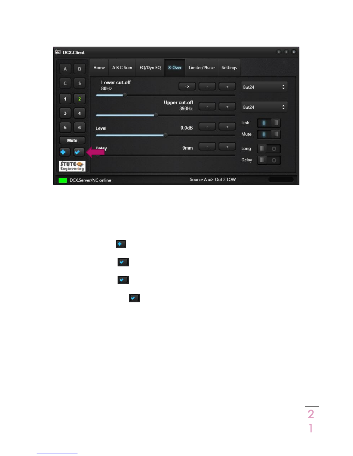
3.2.4 Tab “X-Over”
Control the cut-off frequencies, filter types and delays for the outputs 1 to 6.
Note: You find the details to the described DCX2496 device functions in the device manual.
1
Select a DCX2496 channel.
1..6: Output 1..6
A,B,C,S are disabled
The displayed settings and changes
affects to the selected channel. The
“green” channel number/text indicates
the currently selected channel.
2
Lower cut off (Band- or High-pass)
Band-pass = Lower and Upper filter
type are NOT “off”
Type: Select a filter type from the list
(e.g. L-R 12 or Bessel 24)
Frequency: Adjust the filter cut-off
frequency via the slider or “±”buttons
-> Set “Upper” frequency from
previous channel as “lower”. E.g. LMH
out config. : M Lower = L Upper
3
Upper cut-off (Band- or Low-pass)
Band-pass = Lower and Upper filter
type NOT “off”
Type: Select a filter type from the list
(e.g. L-R 12 or Bessel 24)
Frequency: Adjust the cut-off
frequency via the slider or “±” buttons
4
Link
X-Over link “On” or “Off” (see device
manual DCX2496).
Note: Setting On/Off valid for all
outputs at the same time.
5
Mute/un-mute the selected output
(Output see “star 1”)
6
Output Gain
Adjust the gain for the selected output
via the slider or the “±” buttons
7
Delay settings for the output channel
Long off = Set the short delay values
Long on = Set the long delay values
Adjust the delay value via the slider or
“±” buttons
Delay off = Disable the delay
Delay on = Enable the delay
Warning: Wrong
settings can damage
your loudspeaker!
DCX.Server/DCX.Client/DCX.NC
www.stute-engineering.de
Chapter
: Software description
1
6
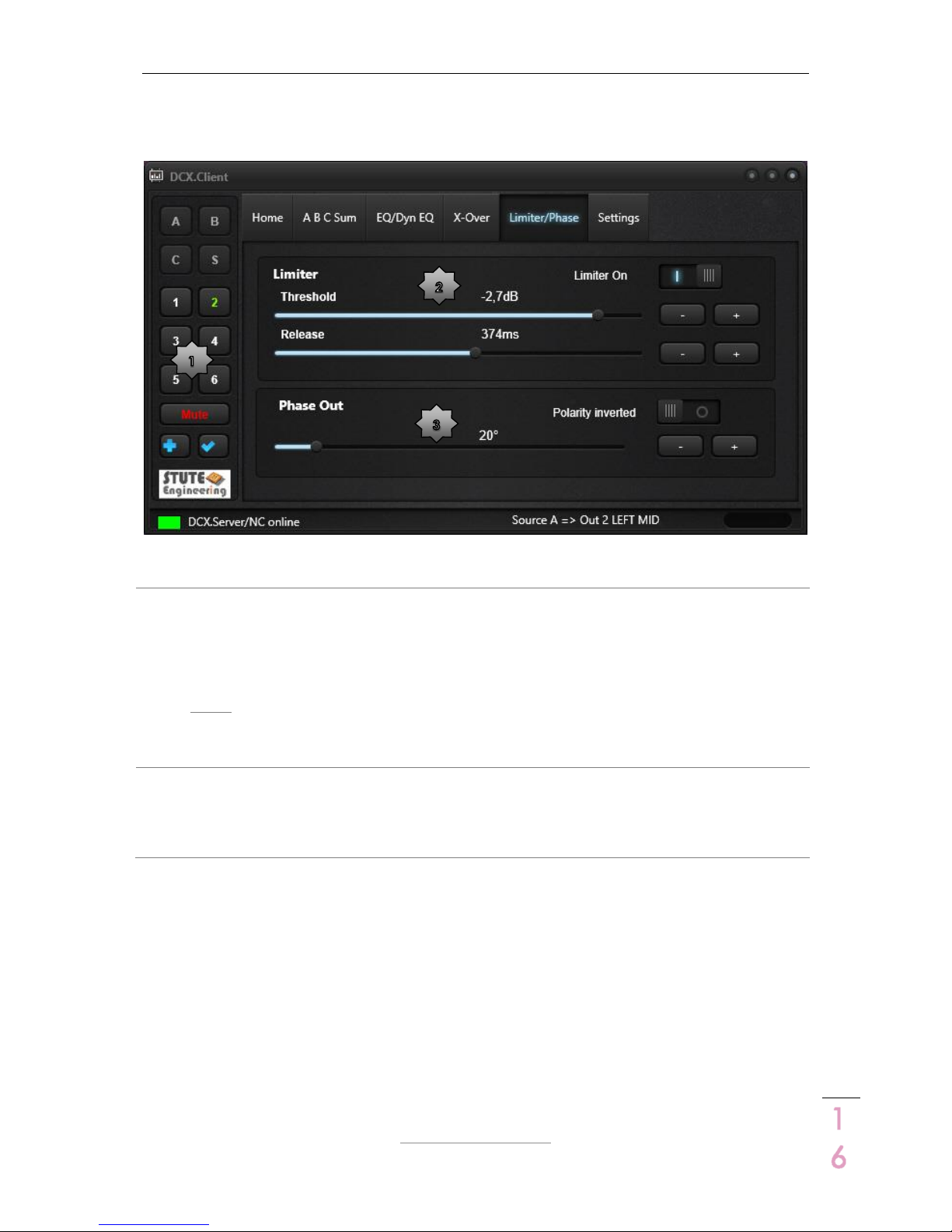
3.2.5 Tab “Limiter/Phase”
Adjust the limiter and phase settings for the output 1 to 6.
Note: You find the details to the described DCX2496 device functions in the device manual.
1
Select a DCX2496 channel.
1..6: Output 1..6
A,B,C,S are disabled
The displayed settings and changes
affects to the selected channel. The
“green” channel number/text indicates
the currently selected channel.
2
Limiter
Set the limiter parameter “Threshold”
and “Release”.
Adjust the values via the slider or “±”
buttons
The switch ”Limiter On”
enables/disables the Limiter for the
selected channel
3
Phase Out
Set phase value via the slider or “±”
buttons for the selected output
You change the polarity with the
switch “Polarity inverted” to: Off=0°
and On=180°
DCX.Server/DCX.Client/DCX.NC
www.stute-engineering.de
Chapter
: Software description
1
7
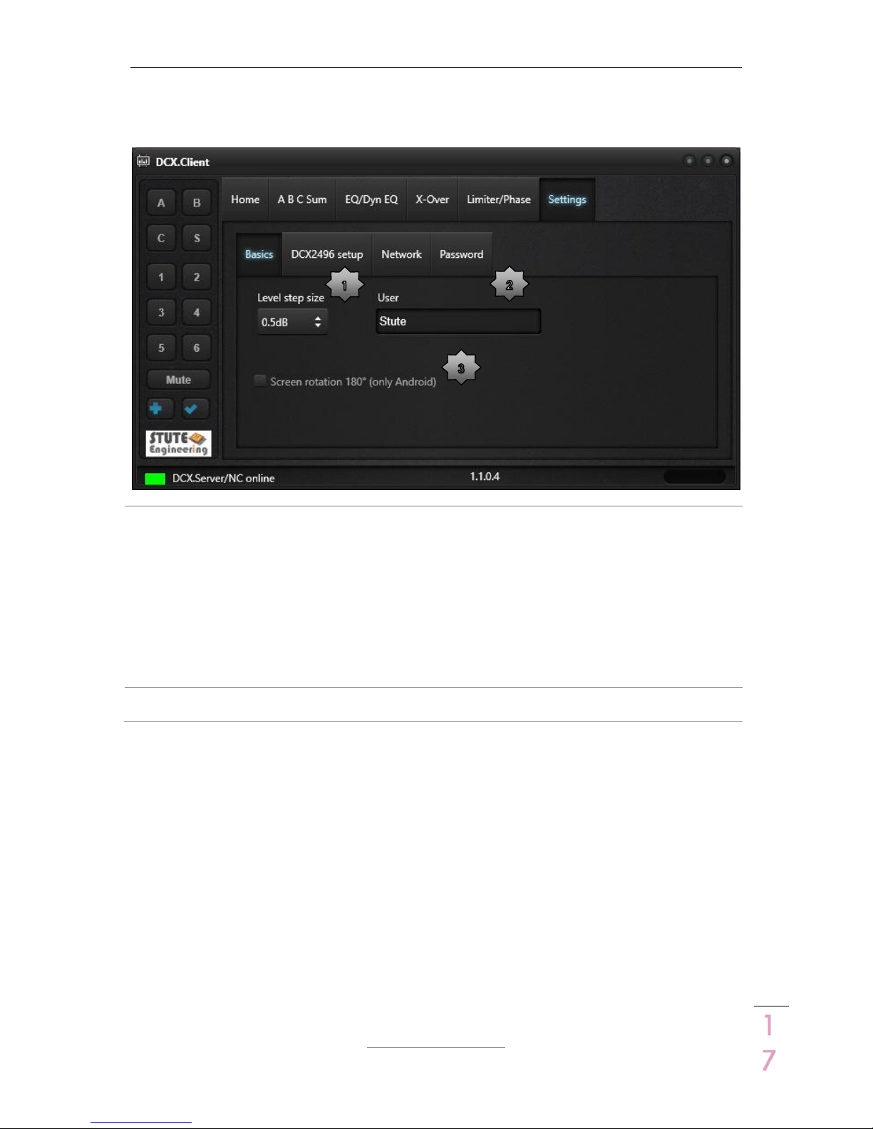
3.2.6 Tab “Settings”
3.2.6.1 Tab „Basics“
1
Level step size: Set the gain size for all
“Gain” slider in dB (Recommended:
value 0.5 or 1 reduces the RS232 and
network data traffic)
Note: A step size different to 0.1dB
(DCX2496 standard) displays rounded
values after the first reading of the
DCX2496 settings. E.g. IN A gain 12.3 will
display as 12.5dB with a step size from
0.5.
2
User: Enter an unique user name for
each client. The name is displayed at
DCX.Server as an indicator who
controls currently the DCX2496.
3
Screen rotation 180° (only for Android)
Rotates the screen to 180°
DCX.Server/DCX.Client/DCX.NC
www.stute-engineering.de
Chapter
: Software description
1
8
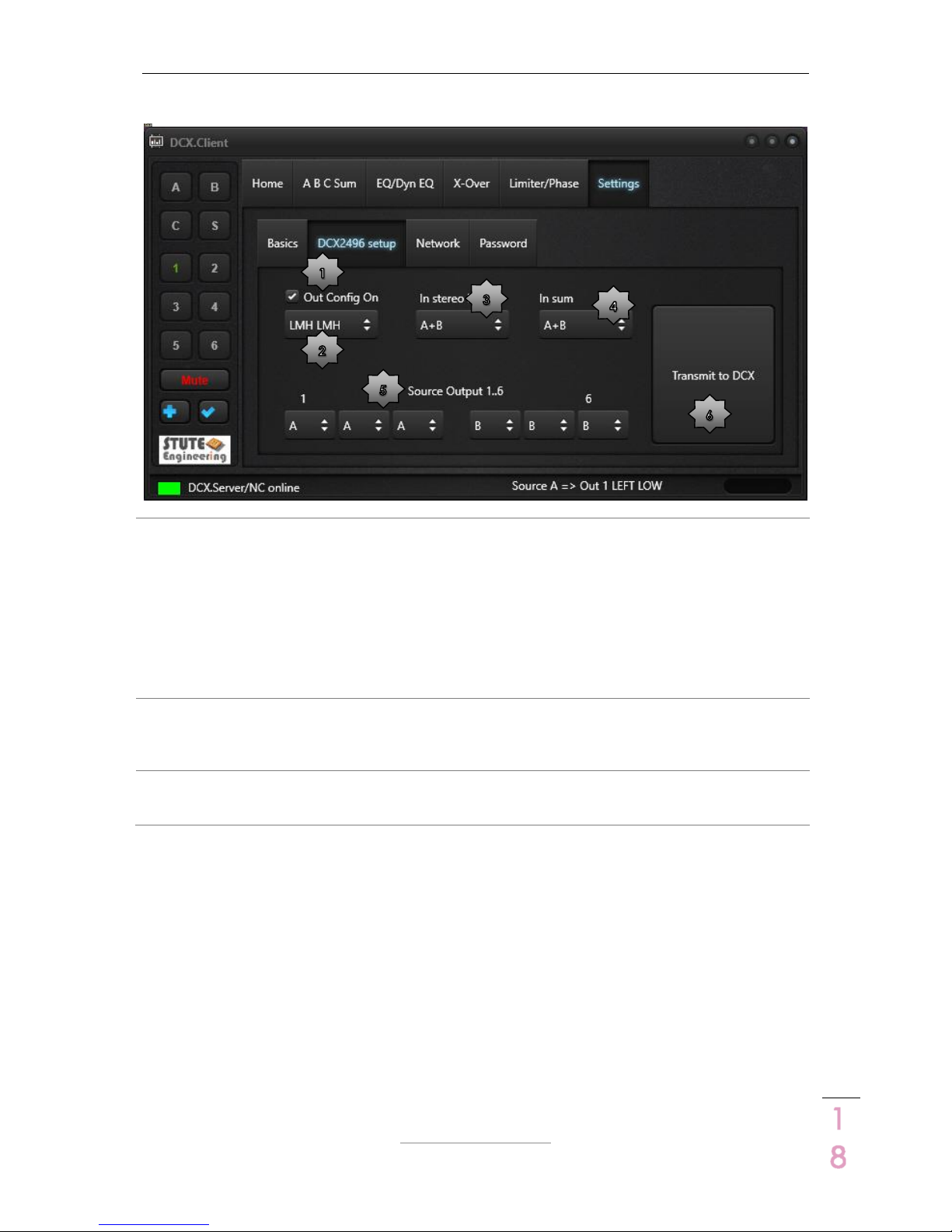
3.2.6.2 Tab „DCX2496“
1
Out Config On: Enable or disable the
Output Configuration setting, see also
star 2.
Note: For more details read the
DCX2496 manual.
2
Out Config: Set a DCX2496 output
configuration
(e.g. Group LMH LMH = Out 1=Low,
Out 2=Mid, Out 3=High, similar for Out
4 to 6. For this configuration channel
1&4, 2&5, 3&6 are linked. Changes at
one channel are automatically
transferred to the linked channel).
Note: Details see DCX2496 manual.
3
In Stereo: Adjust the DCX2496 input
stereo link (e.g. A+B, changes at Input
A are automatically transferred to Input
B)
4
In Sum: Set source signals for SUM
signal (e.g. A+B, Sum = Input A + B)
5
Source Output: Set source for each
output channel (e.g. In A or Sum)
6
Transmit to DCX: Transmit the setup to
DCX2496 device
Note: Check the Behringer DCX2496 manual for more details.

DCX.Server/DCX.Client/DCX.NC
www.stute-engineering.de
Chapter
: Software description
1
9
3.2.6.3 Tab „Network“
1
DCX.Server/NC IP: IP address of the
DCX.Server or DCX.NC device.
Tip: Find the DCX.Server/DCX.NC
controller see “star 3”
2
Port value. Must be identical with the
value from the DCX.Server (default
40000)
3
Find DCX.Server/NC: Button executes a
network request to find the IP address
of the DCX.Server/DCX.NC
4
Display the DCX.Server/NC software
version.
5
Shutdown: Remote shutdown of the
computer where the DCX.Server (incl.
DCX.NC) is executed!
Attention: A shutdown command quit
the DCX.Server MS-Windows system.
Not saved data from other
applications will be lost!
!
DCX.Server/DCX.Client/DCX.NC
www.stute-engineering.de
Chapter
: Software descr
iption
2
0
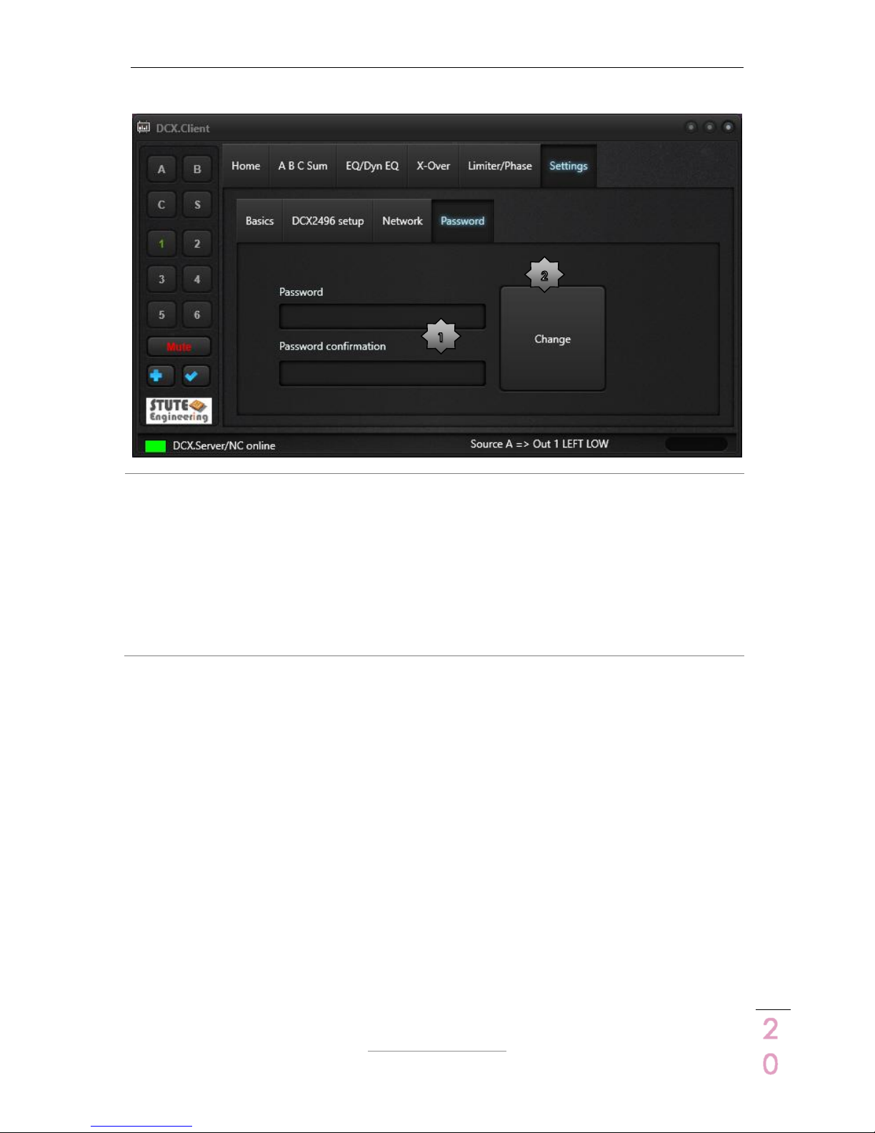
3.2.6.4 Tab „Password“
1
Password: Protect some functions via a
password entry: “Connect/Read..”,
and “Shut down”.
The password is set, when both
password entries “Password” and
“Password confirmation” are the same
and the text “Password” lit green.
2
Change: Press the button “Change” to
set or erase an existing password.
Erase the password input via a two
times blank password entry.
Change an existing password: Enter
first the existing password. Afterwards
enter the new password.
DCX.Server/DCX.Client/DCX.NC
www.stute-engineering.de
Chapter
: Software description
2
1
3.2.7 Undo-Redo Function
With the Undo-Redo Function you compare easily acoustical two different settings of a single
DCX2496 function, e.g. the check of the gain level change for a mid-range speaker for a 3way loudspeaker box.
Steps:
1. Adjust a DCX2496 parameter, like gain level “Out 2” to -5dB.
2. Press the button to the store the last change.
3. Adjust the same parameter to another value, like gain level “Out 2” to -2dB.
4. Press the button to recall the stored value from step 2, for the example gain level
out 2 is set to -5dB.
5. Press the button again to recall the previous value from step 3, for the example
gain level out 2 is set to -2dB.
6. Each repeated press switches between the two values.
Note: The Undo-Redo function is also applicable for cut-off frequencies or delays and other
functions.
Note: The output and input stereo link configuration must be switch off.
DCX.Server/DCX.Client/DCX.NC
www.stute-engineering.de
Chapter
: Control a single or multiple DCX2496 devices
2
2
4 Control a single or multiple DCX2496 devices
Attention: Do not switch off the DCX2496 during an established connection to the DCX.Server
and DCX.Client!
Important: The first DCX2496 must always be powered, when you control multiple DCX2496!
You cannot control the 2nd, 3rd … DCX2496 device without the 1st one.
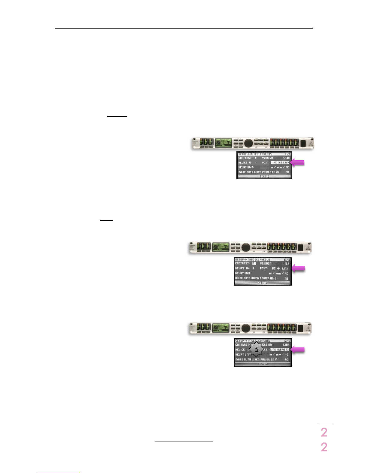
4.1 Control a single DCX2496 device
Connect the USB-RS232 interface with the
RS232 connector from the DCX2496 (rear
side)
DCX2496 adjust “SETUP Miscellaneous”
o Set Port = PC (RS232)
4.2 Control two DCX2496 devices
First DCX: Connect the USB-RS232
interface with the RS232 plug of the
DCX2496 (rear side)
Adjust “SETUP Miscellaneous”
o Set Port = PC Link
Enable/ Push the RS485 “Term” button from the DCX2496 rear side
Second DCX: Connect the 2
nd
DCX2496
with the first via the RS485 connector
Adjust “SETUP Miscellaneous”
o Set Port= LINK (RS485)
Set the Device Id different to the Id from the first DCX2496
o E.g. Device ID =2
Enable/Push the RS485 “Term” button from the DCX2496 rear side

DCX.Server/DCX.Client/DCX.NC
www.stute-engineering.de
Chapter
: Control a single or multiple DCX2496 devices
2
3
4.3 Control more than two DCX2496 devices
First DCX: Connect the USB-RS232
interface with the RS232 plug of the
DCX2496 (rear side)
Adjust “SETUP Miscellaneous”
o Set Port = PC Link
Enable/Push the RS485 bus “Term” button from the DCX2496 rear side
Second DCX: Connect the 2
nd
DCX2496
with the first DCX via the RS485
connector
Adjust “SETUP Miscellaneous”
o Set Port= LINK (RS485)
Set the Device Id different to the Id from the first DCX2496
o E.g. Device ID =2
Disable the RS485 “Term” button from the DCX2496 rear side
Last DCX: Connect the 3
rd
DCX2496 with
the 2nd DCX via the RS485 connector
Adjust “SETUP Miscellaneous”
o Set Port= LINK (RS485)
Set the Device Id different to the other one
o E.g. Device ID =3
Enable/Push the RS485 “Term” button from the DCX2496 rear side
DCX.Server/DCX.Client/DCX.NC
www.stute-engineering.de
Chapter
: DCX.NC controller
2
4
5 DCX.NC controller
Control your DCX2496 direct from your tablet or mobile
phone, without a MS-Windows computer for the DCX.Server
software.
Technical features
Plug & Play DCX.Server
Network connection: LAN
Small size 12x12x2.5cm
Note: The DCX.NC controller needs approx. 50 seconds to be active. Connection tries before
the system get active, will be ignored.
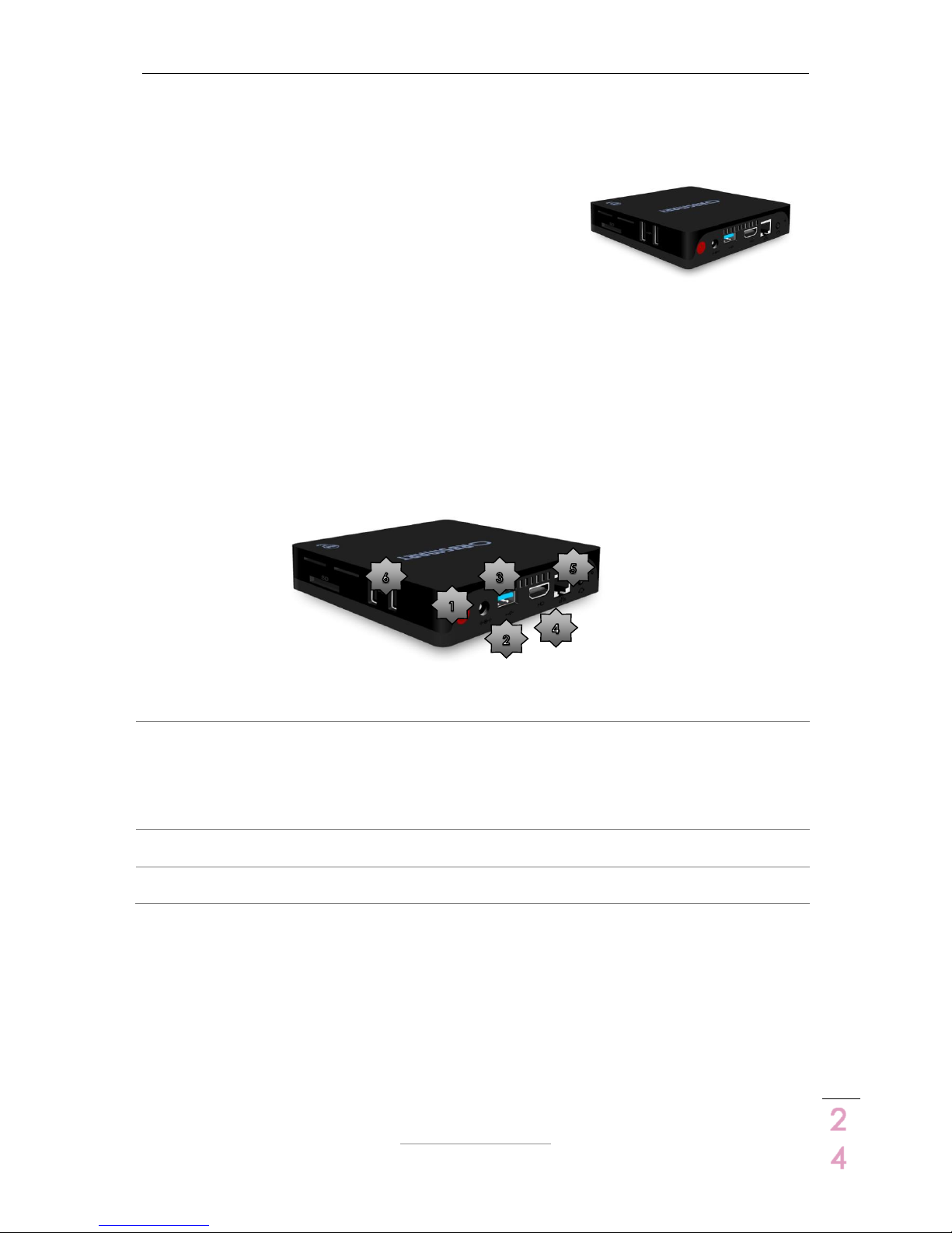
5.1 Connectors
1
Power switch
Power on: Push the button. The blue in
the front of the controller glows
Power off: Use the shutdown function of
the DCX.Client. In error cases hold the
button until the blue led is switched off.
2
Power supply connector
Connect the delivered power supply
with the connector
3
USB port: Connect the delivered USB-
RS232 interface with this port
4
HDMI output (optional)
Not used
5
LAN network interface (plug for a LAN
cable)
6
Additional USB ports
Not used
Attention: Do not switch off the controller during an established connection to the DCX.Client!
Disconnect the USB-RS232 interface only in the switched off status. Otherwise a reboot of the
DCX.NC system is needed!
5.2 LAN connection
The system is pre-configured to work with a wired network connection. Connect the controller
with your network router (like Fritzbox) via a LAN cable. The controller gets the IP address from
your network router via DHCP.
DCX.Server/DCX.Client/DCX.NC
www.stute-engineering.de
Chapter
: Software license key (DCX.Server)
2
5
5.3 Software update controller DCX.NC
Connect a USB keyboard/mouse and monitor (HDMI) with the controller. Execute the
“DCX.Server Update” program icon. Otherwise send the controller to Stute Engineering for
maintenance.
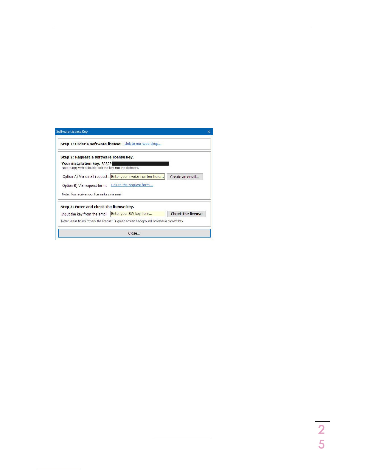
6 Software license key (DCX.Server)
Without a valid software license key the DCX.Server software runs in the TRAIL mode. The limits
are: The DCX.Client controls only the Inputs A..C of your DCX2496. Order via the license
assistant your key.
Note: The DCX.Client (MS-Windows, macOS. iOS, Android) is free of charge and needs no
license key.

DCX.Server/DCX.Client/DCX.NC
www.stute-engineering.de
Chapter
: FAQ
2
6
7 FAQ
7.1 DCX.Server
LED
Server IP shines yellow
DCX.Client software not connected to the server.
COM port LED shines red
USB-RS232 interface not connected to the
PC/DCX.NC
COM port LED shines yellow
Scan for DCX2496 devices ongoing. Please wait.
DCX2496 shines red
DCX2496 is switched off or RS232 interface not
connected to the DCX2496
Messages (footer)
No COM port detected
No USB-RS232 interface connected or RS232 driver
missed
COM x not found
No USB-RS232 interface connected or RS232 driver
missed
Screen “Select port” (after pressing „Change COM port…)
No serial ports listed
No USB-RS232 interface connected or installed
7.2 DCX.Client
7.2.1 Messages (footer)
DCX.Server/NC offline
DCX.Server not found…
DCX.Server/DCX.NC not started or firewall/
network issues.
Check the firewall settings. Allow the
communication.
Check: Is at your tablet/mobile phone Wi-Fi
deactivated?
DCX.Server PC needs a wired LAN connection
See also chapter 7.2.3
DCX2496/RS232 interface not connected
DCX2496 switched off or USB-RS232 interface not
connected to the DCX2496. Connect the
interface and re-start DCX.Server or DCX.NC
DCX2496 offline
DCX2496 powered off/not connected
DCX2496 device powered off or USB-RS232
interface not connected to the RS232 connector
from the DCX2496 (rear side)
Ensure that in a DCX2496 cluster the 1st DCX2496
device is always powered!
Select a DCX Id and connect…
Message to the program start or after a
disconnection.
Next step: Connect the software to the DCX2496
and import the settings via the button
“Connect/Read DCX…” from the “Home” tab.

DCX.Server/DCX.Client/DCX.NC
www.stute-engineering.de
Chapter
: FAQ
2
7
Note: The software switch automatically to the
“Home” tab until the data is read from the
DCX2496
RS232/COM error DCX.Server
USB-RS232 interface malfunction or not
connected to your computer (DCX.Server/
DCX.NC)
DCX.Server software version not supported
DCX.Client does not support the DCX.Server
version
Warning. Another client is connected!
Two or more DCX.Client’s are connected to the
DCX.Server. Allowed are one. Close all not
needed DCX.Client’s
Case “Password forgotten”
Enter “Stute Engineering” to reset the password
Enable Wi-Fi…
Wi-Fi is disabled at your device (e.g. mobile
phone). Enable Wi-Fi for a proper work
7.2.2 DCX2496 values: Gain, threshold, frequency,…
Values of Frequency, Delay, Phase … change in a
step size > 1
Many values of the DCX2496 can only be
changed in a device pre-defined step size, for
example delay short in 2mm steps and long in
5cm steps
Gain Input / Output steps are different to 0.1dB
The steps size can be adjusted: 0.1dB, 0.5dB,
1.0dB. See tab “Settings”
Recommended: 0.5dB
Tab “X-Over”: Frequency adjustments at channel
2 “Upper” change the frequency from channel 3
“Lower”, or channel 2 “Lower” the frequency
“higher” from channel 1 (Output configuration
LMH LMH)
DCX2496 X-Over Link function enabled (see
DCX2496 manual). Disable the function with the
client: tab “X-Over” switch “Link”
Tab “X-Over”: Text color “Lower” and “Upper cut-
off” is red
Band-pass mode (upper & lower filter type not
off): Invalid value, lower frequency > upper
frequency. Change lower or upper.
Tab “X-Over”: Gain value changes from channel
1 are automatically synchronized with channel 4
(Output configuration LMH LMH)
DCX2496 Output configuration enabled (See
DCX2496 manual). In the sample configuration
LMH LMH L=1 & 4 are linked
The parameter for X-Over, Gain.. are different to
original preset data source after the copy of a
preset
The target device has a different Input / Output
configuration (like LMH LMH, see DCX2496
manual) than the source.
7.2.3 Network / App
Server connection not possible
Check the IP address/Port of the DCX.Server and
Client:
Check the IP list from the DCX.Server and select a
valid IP address. Example:
- DCX.Client computer IP: 192.168.178.44 (MSWindows command to view the IP of the PC:
cmd/ipconfig)
- DCX.Server computer IP: 192.168.195.1 select
another IP, e.g. 192.168.178.72
Server connection not possible
See chapter “messages footer 7.2.1” above:
Firewall settings
App quits immediately after start
Activate Wi-Fi at your device or connect the
device with a network cable to the network router

DCX.Server/DCX.Client/DCX.NC
www.stute-engineering.de
Chapter
: FAQ
2
8
7.2.4 With DCX.NC controller
Network connection not possible
The boot procedure needs approx. 50 sec. Wait
until the DCX.Client displays a green panel in the
footer: Message “DCX.Server/NC online
Network connection not possible
Check the DCX.NC LAN cable
Network connection not possible
Check the power supply of the DCX.NC
Network connection not possible
Shut down and re-start the DCX.NC (See chapter
5)
7.3 DCX.NC
7.3.1 Power supply
Blue LED at the front is off
Check the power supply/power supply
connection
Blue LED at the front is off
Switch the DCX.NC controller on at the rear side
How to power off the DCX.NC?
Switch off the DCX.NC via the client: Tab
“Settings” button “Shutdown…”
7.3.2 Network
IP address of the DCX.NC is unknown
DCX.Client scans at the first start automatically for
the DCX.Server and adds the IP in the textbox.
Optional press the button “Find DCX.Server…”
from the tab “Settings/Network”

DCX.Server/DCX.Client/DCX.NC
www.stute-engineering.de
Chapter
: System requirements
2
9
8 System requirements
8.1 DCX.Server software
Computer with a wired LAN connection
Operating system MS-Windows 7,8,10 (32 & 64 bit)
1xUSB 2.0 port (USB-RS232 interface)
CPU min. Intel i3 processor, 1.5GHz or faster (or adequate AMD type), 2GB RAM
8.2 DCX.Client software
8.2.1 MS-Windows (PC)
Operating system MS-Windows 7,8,10 (32 & 64 bit)
CPU min. Intel i3 processor, 1.5GHz or faster (or adequate AMD type), 2GB RAM
8.2.2 macOS
Operating system OS X El Capitan or higher
8.2.3 Android
Note: Use “syscheck” from the Google app store to check the requirements
Operating system Android 5 or higher
CPU Cortex-A Series, ARM64
NEON technology supported
Screen min. 680x360pixel
8.2.4 iOS
Operating system iOS 9 or higher
iPhone 6 or higher
8.3 DCX.NC
Power supply 110Vac..240Vac @ 50Hz/60Hz
Ethernet network connection (RJ45) 100Mbit or 1000Mbit
8.4 USB-RS232 interface requirements
Min. supported baud rate: 38.400 baud
Support of the RTS control signal
USB 2.0 bus or higher
Interface recommended with FTDI chip set
Note: Proofed interfaces are offered in our online store.
©Copyright 2018 Stute Engineering. All rights reserved. Subject to change.
 Loading...