

Page 1

Model 82 Stereo Analog
Audio Distribution Amplifier
User Guide
Issue 1, January 2000
This User Guide is applicable for serial numbers:
Model 82 M82-00151 and later
Copyright © 2000 by Studio Technologies, Inc., all rights reserved
5520 West Touhy Avenue
Skokie, Illinois 60077 U.S.A.
Telephone (847) 676-9177
Fax (847) 982-0747
www.studio-tech.com
50205-100, Issue 1
Page 2

Page 3

Table of Contents
Foreword...................................................................... 5
Introduction .................................................................. 7
What This User Guide Covers ................................. 7
System Overview ..................................................... 7
System Features ...................................................... 7
Installation .................................................................... 8
Configuration ............................................................... 10
Operation ..................................................................... 11
Troubleshooting ........................................................... 11
Technical Notes ........................................................... 12
Specifications............................................................... 13
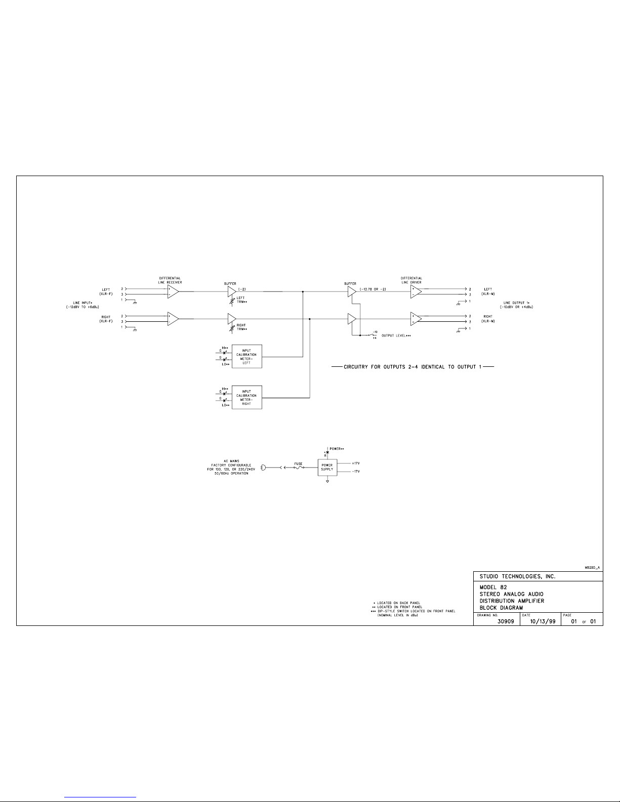
Block Diagram
Model 82 User Guide Issue 1, January 2000
Studio Technologies, Inc. Page 3
Page 4

This page intentionally left blank.
Issue 1, January 2000 Model 82 User Guide
Page 4 Studio Technologies, Inc.
Page 5

Foreword
I am pleased to present the Model 82 Stereo Analog Audio Distribution Amplifier.
As president of Studio Technologies, I take a very personal approach when
designing products. Getting older (43 as of this writing) has increased my
appreciation of the more subtle things in lifebe they a part of nature or the
nuances contained in a well-designed piece of electronic equipment. Do the
technical and operational aspects of a product work together to feel right? A
Studio Technologies design is ready to go only when I am completely satisfied.
Many fine people worked toward making the Model 82 happen. Mitch Budniak
(ace consulting engineer) designed many of the circuits. Jim Cunningham contributed to the analog design. Carrie Loving provided engineering support. Al
Lux designed the printed circuit board. Fred Roeck performed the mechanical
design. Joe Urbanczyk coordinated the safety testing and agency approvals.
Please contact me with your questions, comments, and suggestions. I can be
reached by voice at (847) 676-9177, fax at (847) 982-0747, or via the Internet @
www.studio-tech.com.
Sincerely,
Gordon K. Kapes
President
Model 82 User Guide Issue 1, January 2000
Studio Technologies, Inc. Page 5
Page 6

This page intentionally left blank.
Issue 1, January 2000 Model 82 User Guide
Page 6 Studio Technologies, Inc.
Page 7

Introduction
The Model 82 Stereo Analog Audio
Distribution Amplifier was developed by
Studio Technologies as part of its Studio
Tools group of audio support products.
construction standards make the Model
82 suitable for continuous operation, even
for on-air broadcast applications.
System Features
One Stereo Input
The Model 82 is designed to work in a
large variety of applications. Specific
applications include audio production,
duplication, broadcast, and sound reinforcement. All Model 82 functions meet
or exceed the performance of the most
expensive high end audio equipment.
What This User Guide Covers
This User Guide is designed to assist you
when installing, configuring, and using the
Model 82 Stereo Analog Audio Distribution
Amplifier.
System Overview
The Model 82 from Studio Technologies,
Inc. is a distribution amplifier that truly
meets the needs of the real world. The
stereo input is intended to connect to
virtually any line-level audio source.
The ExactCal input calibration section
allows optimal audio performance to be
achieved over a nominal input level range
of 12dBV to +6dBu. The four stereo
outputs meet exacting professional standards. Capable of driving balanced or
unbalanced loads, each output can drive
+26dBu into 600 ohms. Using front panel
switches, each stereo output can be
individually configured for a nominal
output level of 10dBV or +4dBu.
The front-panel trim potentiometers and
LEDs make calibration and use simple.
The AC mains input power is factory
configured for 100, 120 or 220/240V,
50/60Hz operation. Components and
The differential input circuitry is compatible with balanced or unbalanced signals
having a nominal level range of 12dBV to
+6dBu. Using laser-trimmed components,
the stereo input offers superior commonmode signal rejection. To achieve optimal
audio performance the ExactCal calibration section matches the installationspecific nominal input level with the Model
82s internal gain structure. Two 15-turn
trim potentiometers and four LEDs allow
fast, precise calibration. Unlike other
distribution amplifiers, the Model 82 ensures that excellent audio performance
can be achieved with little or no hassle.
Four Stereo Outputs
The Model 82 contains four independent
stereo output sections. For compatibility
with a range of facilities, each output
section can be separately configured for
a 10dBV or +4dBu nominal output level.
Each output features an electronically
balanced circuit capable of driving balanced or unbalanced loads. And, unlike
some output circuits, operating a Model
82 output in an unbalanced configuration
does not cause a change in the nominal
output level. Short circuit resistant, the
rugged output circuits can drive full signal
levels into 600 ohm or greater loads.
The Model 82s architecture precludes the
need for individual output-level trim potentiometers. With the input signal calibrated
using the ExactCal section, the four stereo
outputs use 1%-tolerance components
Model 82 User Guide Issue 1, January 2000
Studio Technologies, Inc. Page 7
Page 8
to provide precise 10dBV or +4dBu
outputs.
Audio Performance
The Model 82 is the result of exacting
circuit design combined with the latest
state-of-the-art components. Like all
Studio Technologies products, the Model
82 has survived tough listening evaluations by industry professionals. These
veterans have the ears to guide us in
achieving the right performance. The
outcome is a product that achieves
sonic excellence.
Design Philosophy
is desired in virtually every distributionamplifier applications are multiple audio
outputs all operating at a standard reference level. By implementing the ExactCal
system, the Model 82s internal operating
level can be easily calibrated to match that
of the input signal. Once this input level
matching is accomplished the four stereo
outputs can be individually configured for
10dBV or +4dBu nominal operating
level. In conclusion, output trim pots are
not included on the Model 82 for the
simple reason that better audio performance can be achieved without them!
Most audio distribution amplifiers contain
a level trim adjustment on each output.
After careful study Studio Technologies
concluded that these adjustments confused, and often interfered with, the
process of getting maximum audio
performance. After checking with personnel in the field, it became clear that what
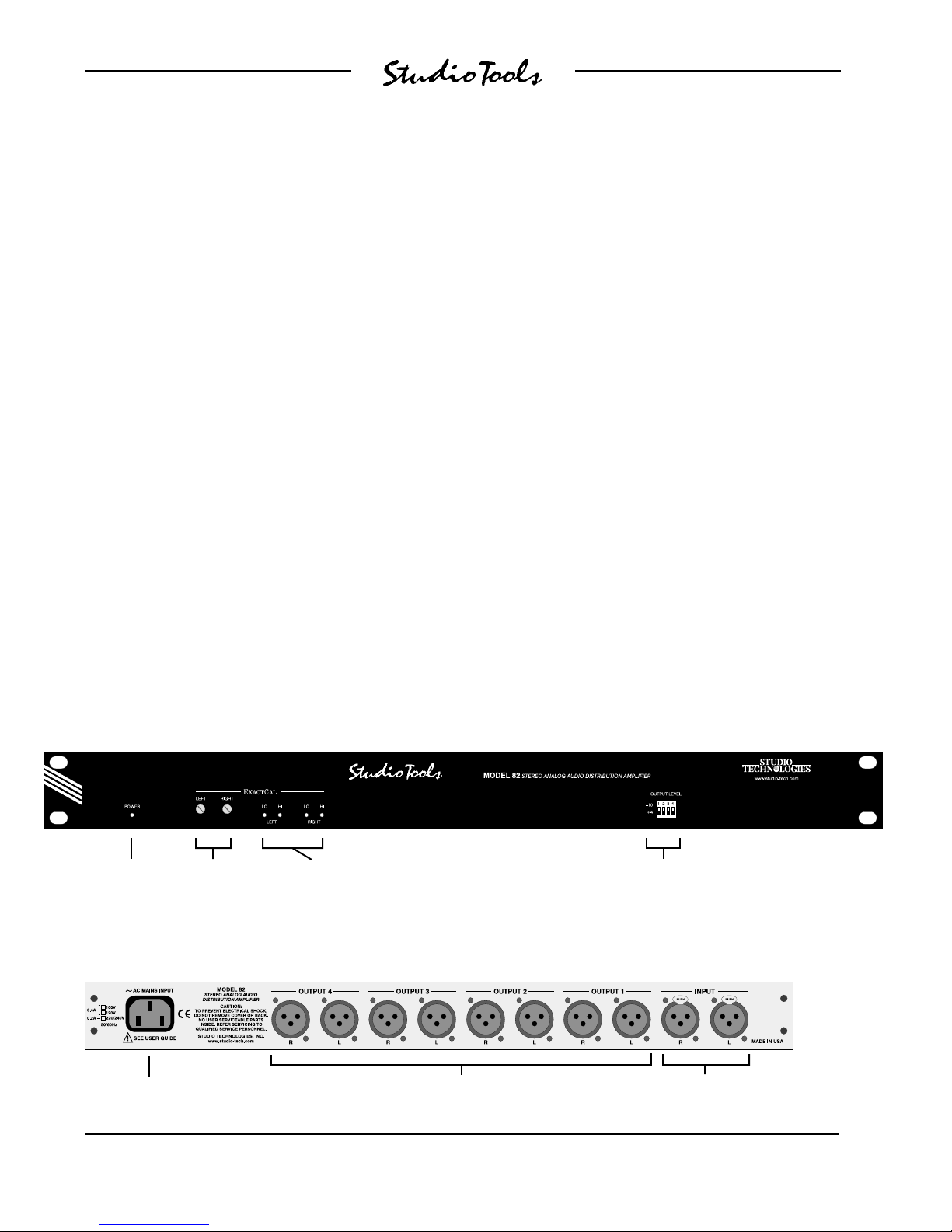
Model 82 Front Panel
Power
present LED
Left and
right input
trim controls
Input level
calibration LEDs
Model 82 Back Panel
Installation
In this section you will be installing the
Model 82 in an equipment rack. Audio
input, audio output, and AC mains power
connections will be made.
10dBV or +4dBU output
level configuration switches
AC mains
connection
Issue 1, January 2000 Model 82 User Guide
Page 8 Studio Technologies, Inc.
Stereo line-level
outputs
Stereo line-level
inputs
Page 9

System Components
The shipping carton contains a Model 82,
User Guide, and warranty card. Units
destined for North America are shipped
with an AC mains cord. Your dealer or
distributor will provide an AC mains cord
for non-North American destinations.
low ( or cold), and pin 1 is shield. With an
unbalanced source, connect pin 2 to high
(+ or hot), and pins 1 and 3 to shield. If
connecting to an unbalanced source in
this manner results in hum or noise, try
connecting pin 2 to high (+ or hot) and
pin 3 to shield; leave pin 1 unterminated.
Mounting the Model 82
The Model 82 requires one space in a
standard 19-inch (48.3cm) equipment
rack. It is desirable to locate the Model 82
to allow easy access to both the front and
the back panels. The back panel contains
the input and output connectors. The front
panel is used to access the calibration
controls and output-level switches. The
front panel also contains four LED level
indicators. The Model 82 is secured to
the equipment rack using two mounting
screws per side.
Audio Input
The Model 82 provides one stereo linelevel input. It is electronically balanced,
and compatible with balanced or unbalanced signals that have a nominal level
range of 12 dBV to +6dBu. The ExactCal
section allows precise level calibration
with the connected input signal. The
configuration section of this guide provides details on using the trim pots.
It is anticipated that in most cases a stereo
signal will be connected to the input. The
Model 82 can also be used as a 1-input/
8-output monaural distribution amplifier,
or as a dual 1-input/4-output monaural
distribution amplifier.
Two 3-pin female XLR-type connectors are
used to interface with the input source.
Prepare the mating connectors (males) so
that pin 2 is signal high (+ or hot), pin 3 is
Audio Outputs
The Model 82 contains four independent
stereo line-level outputs. The outputs are
electronically balanced and capable of
driving balanced or unbalanced loads of
600 ohm or greater. The outputs can be
individually configured for a nominal
output level of 10dBV or +4dBu, so you
can connect to all line-level inputs with no
hassle.
Eight 3-pin male XLR-type connectors are
used to interface with the Model 82's
outputs. Prepare the mating connectors
(females) so that pin 2 is signal high (+ or
hot), pin 3 is low ( or cold), and pin 1 is
shield. To connect to an unbalanced load
connect pin 2 as signal high (+ or hot),
and pins 1 and 3 as signal low/shield. For
optimal unbalanced operation, it is important to connect pins 1 and 3 together
directly on the connector that mates with
the Model 82, and not on the other end
of the cable.
Note that while the Model 82s electronically balanced output circuits are capable
of driving loads of 600 ohms or greater,
the output level will drop slightly as the
load impedance approaches 600 ohms.
A 0.5dB difference in output level can be
expected as the load impedance changes
from 10k ohms to 600 ohms.
AC Mains Power
The Model 82 is internally configured to
operate from either 100, 120, or 220/240V,
Model 82 User Guide Issue 1, January 2000
Studio Technologies, Inc. Page 9
Page 10

50/60Hz. In most cases, units shipped to
North America are factory selected for
120V operation. Units bound for Japan are
selected for 100V, while our friends down
under and in Europe receive units set for
220/240V. Before connecting the Model 82
to AC mains power, check that it is configured to match the local mains voltage.
Look on the back panel, adjacent to the
power entry connector, for the configured
voltage(s). Note that an incorrect configuration could seriously damage the unit.
Should it be necessary to change the
units operating voltage it must be
performed only at the factory or by an
authorized service technician.
The Model 82 uses an IEC standard connector to mate with the AC mains cord.
The wire colors in the AC mains cord
should conform to the internationally
recognized CEE color code and must
be wired accordingly:
Connection Wire Color
Neutral (N) Light Blue
Line (L) Brown
Protective Earth (E) Green/Yellow
Safety Warning: The Model 82 does
not contain an AC mains disconnect
switch. As such the mains cord plug
serves as the disconnection device.
Safety consideration requires that
the plug and associated outlet be
easily accessible to allow rapid disconnection of mains power should it prove
necessary.
Configuration
Input Level Calibration
With the ExactCal calibration section its
simple to match the nominal level of the
input signal with the Model 82s internal
circuitry. Two 15-turn trim potentiometers,
along with four LEDs, form the ExactCal
section. One trim pot is associated with
the left input, the other with the right. Two
LEDs, labeled Lo and Hi, are associated
with each input. They are provided as an
aid to calibration, as well as serving as
signal present indicators.
The following is a step-by-step procedure
for using the ExactCal section to match an
input signal to the Model 82's circuitry:
Set the trim pots to their fully counter-
clockwise position. Remember, the
trim pots are 15-turn type, so you may
have to rotate them up to 15 times
before reaching their fully counterclockwise position.
Supply a 1kHz sine wave to both the
left and right inputs. Set the level of the
source to be precisely the nominal
operating level. If, for example, the
output of a console is connected to
the input of the Model 82, the console
output should be adjusted so that the
meters read 0dB or 100%. If the output
of the console is a +4-type, then
setting the consoles left and right
output levels to nominal should find
the console output levels to be exactly
+4dBu.
As soon as mains power is connected, the
Model 82s power present LED will light.
The unit is now ready for years of trusty
service!
Issue 1, January 2000 Model 82 User Guide
Page 10 Studio Technologies, Inc.
Slowly turn the trim pot associated with
the left input in the clockwise direction.
As you increase the level, watch the
LEDs associated with the left channel.
Page 11

The LED labeled Lo will light first, then
both LEDs will light, then only the LED
labeled Hi will light. The correct setting
is where both LEDs light their brightest.
Careful adjustment is required as the
window where both LEDs light is
somewhat less than 1dB.
Repeat the above procedure for the
trim pot and LEDs associated with
the right input. When the configuration
is correct both LEDs associated with
the right channel input will be lit to their
brightest.
Disconnect the 1kHz signal and con-
nect the normal audio source.
Output Level Selection
Each of the four stereo line-level outputs
is individually configurable for a 10dBV
or +4dBu nominal output level. Four DIPtype switches, located on the right side of
the front panel, are used to set the output
levels. The legend on the switches correspond to the output channel numbers. A
switch that is set to its up position configures its associated output channel for
10dBV. A switch set to its down position
configures the output for +4dBu. A small
screw driver may be of assistance when
setting the switches.
The LEDs labeled Lo will light whenever
an input signal is within the range of 18dB
below and 0.5dB above the nominal operating level. The LEDs labeled Hi will light
any time an input signal is greater than
0.5dB below the nominal operating level.
This sounds a bit confusing but isnt really
so hard to understand. As an example, if
you have a nominal +4 signal connected to the Model 82s line input and
the ExactCal section has been used to
calibrate the input, the Lo LEDs will light
whenever the signal is between 14 and
+4.5dBu, the Hi LEDs will light whenever
the signal exceeds 3.5dBu.
The four outputs are fully independent.
You can patch, reconnect, or even short
out an interconnecting cable without
effecting the other outputs. Using the
front-panel DIP switches you can change
the output level of any or all of the outputs
whenever you wish.
Remember that if you change the input
source you may need to use the ExactCal
section to recalibrate the input. Refer to
the configuration section of this guide for
details.
Troubleshooting
Operation
Now that youve installed and configured
the system, youre ready to go. You
should find operation very easy, as there
is nothing to do on a day-to-day basis. For
peace of mind, the ExactCal LEDs will give
you a visual indication whenever audio
signals are present on the Model 82s
input.
Model 82 User Guide Issue 1, January 2000
Studio Technologies, Inc. Page 11
If youre having problems getting the
Model 82 up and running, this section can
help. If you havent read the other sections
of this guide, you should do so before
proceeding.
If the Model 82 Doesnt Work At All
A source of AC mains power must be
connected to the Model 82. Depending on
the version you have purchased, 100, 120,
or 220-240Vac, 50/60Hz is required. Confirm what mains voltage is required by
Page 12

observing the selection boxes to the left
of the AC mains connector on the back
panel. Whenever mains power is connected the front panel power present LED
should light. If the LED is not lit confirm
that AC mains power is active (hot) and
that the cord is securely mated with the
connector on the Model 82's back panel.
For safety in the event of a major internal
failure or the connection of incorrect AC
mains voltage, the Model 82 contains a
fuse inside its cabinet. The fuse will open
(blow) if the failure of an internal component causes excessive current to be drawn
from the internal power supply. The fuse
will also open should 220-240Vac be
connected to a Model 82 that is configured for 100 or 120Vac operation. The
fuse is intended to be replaced only by a
competent service technician. This person
will have the training to safely access the
guts of the Model 82 and identify where
a problem is located.
Incorrect Output Levels
You must correctly set the input trim pots
so that the four stereo outputs can provide
precise 10dBV or +4dBu nominal output
levels. These trim pots are used to match
the nominal level of the audio input signal
with the Model 82s internal circuitry. Refer
to the Configuration section of this guide
for detailed instructions.
it was easy to say that 0dBm is 1 milliwatt
dissipated in the known load (i.e., 0dBm
across 600 ohms will measure 0.775V). In
contemporary situations an output is rarely
terminated with 600 ohms; generally 10k
ohms or higher. The dBu designation is
better because it refers to dB referenced
to 0.775V, with no reference to load impedance. This takes into account todays
audio scene where signals have a low
source impedance, and a high input
impedance. The dBu designation is becoming the standard for the professional
audio industry.
10dBV Outputs
Note that a user monitoring, by means of
a level meter (e.g., a VU meter), one of the
Model 82s outputs might expect to see a
14dB drop when changing from the +4 to
the 10 DIP switch position. In fact, the
output level will drop by only 11.78dB.
This is because the output level is not only
switching between "+4" and "10," but it's
changing from a dBu to a dBV reference
as well. As 10dBV is the same as
7.78dBu, the expected 14dB drop never
occurs!
Technical Notes
Definition of LeveldBu
Whenever possible, Studio Technologies
has opted to use the dBu designation as
it seems to be quite rational. Using dBm
was fine when all audio line outputs were
terminated with 600 ohm loads. In this way
Issue 1, January 2000 Model 82 User Guide
Page 12 Studio Technologies, Inc.
Page 13

Specifications
Audio Input: 1, stereo
Type: electronically balanced, direct coupled
Input Compatibility: can be connected to
balanced or unbalanced signals
Impedance: 24k ohms
Nominal Input Level: 12dBV to +6dBu
Input Level Control: 15-turn trim potentiometers
allow calibration over 12dBV to +6dBu input
range
Maximum Input Level: +27dBu
Common Mode Rejection: 90dB @ DC and
60Hz, 85dB @ 20kHz, 60dB @ 400kHz (typical)
Audio Outputs: 4, stereo
Type: electronically balanced, direct coupled,
intended to drive loads of 600 ohms or greater,
can be connected balanced or unbalanced
Nominal Output Level: 10dBV or +4dBu, each
output individually switch configurable
Maximum Output LevelBalanced: +27dBu
into 10k ohms, +26dBu into 600 ohms
Maximum Output LevelUnbalanced: +21dBu
into 10k ohms, +20dBu into 600 ohms
Output Impedance: 50 ohms
Frequency Response: 10Hz-70kHz +0/0.5dB
(down 1dB @ 90kHz)
Distortion (THD+N): 0.004% (measured at
+4dBu input, +4dBu output, 20Hz-20kHz)
S/N Ratio: 92dB (20Hz-20kHz, ref. +4dBu on
input and output)
Crosstalk: 86dB (1kHz, ref. +4dBu on input and
output)
LED Indicators: 5, 1 power present, 4 input level
calibration
Fusing: 1
Type: 5 x 20mm time lag (Littelfuse 218-series or
equivalent)
Rating: 0.400A for 100 and 120V mains power,
0.200A for 220/240V mains power
Connectors:
Audio Input: 2, 3-pin XLR-type, female
Audio Output: 8, 3-pin XLR-type, male
AC Mains: standard 3-blade plug, meets IEC 320
specifications
AC Mains Requirement:
100, 120, or 220/240V, ±10%, factory configured,
50/60Hz, 100-120V 0.4A maximum, 220/240V
0.2A maximum
Dimensions (Overall):
19.00 inches wide (48.3cm)
1.72 inches high (4.4cm)
6.65 inches deep (16.9cm)
Mounting:
One space in a standard 19-inch-type rack
Weight:
7.0 pounds (3.2kg)
Specifications and information contained in this
User Guide subject to change without notice.
Model 82 User Guide Issue 1, January 2000
Studio Technologies, Inc. Page 13
Page 14

This page intentionally left blank.
Issue 1, January 2000 Model 82 User Guide
Page 14 Studio Technologies, Inc.
Page 15
 Loading...