

Page 1

Model 5401
Dante™ Master Clock
User Guide
Issue Preliminary 4, May 2018
This User Guide is applicable for serial numbers
M5401-00151 and later with application firmware 1.02 and later
and Dante firmware 1.1.0 (Brooklyn II 3.10.2.2) and later
Copyright © 2018 by Studio Technologies, Inc., all rights reserved
www.studio-tech.com
50609-0518, Issue Preliminary 4
Page 2

This page intentionally left blank.
Page 3

Model 5401
DANTE MASTER CLOCK
Table of Contents
Revision History ........................................................... 4
Introduction ................................................................... 5
Installation ......................................................... Pending
Configuration ................................................................ 8
Operation ........................................................... Pending
Technical Notes ................................................. Pending
Specifications ............................................................... 19
Appendix A–Sync Input Sources .................................. 21
Appendix B–Model 5401 Menu Structure ..................... 22
Appendix C–PTP v2 (IEEE-1588-2008)
Characteristics ..............................................................23
Model 5401 User Guide Issue Preliminary 4, May 2018
Studio Technologies, Inc. Page 3
Page 4

Model 5401
DANTE MASTER CLOCK
Revision History
Issue Preliminary 4, May 2018:
• Additional text and improvements.
Issue Preliminary 3, November 2017:
• Additional text and improvements.
Issue Preliminary 2, October 2017:
• Additional text and improvements.
Issue Preliminary 1, October 2017:
• Initial release.
Issue Preliminary 4, May 2018 Model 5401 User Guide
Page 4 Studio Technologies, Inc.
Page 5
Model 5401
DANTE MASTER CLOCK
Introduction
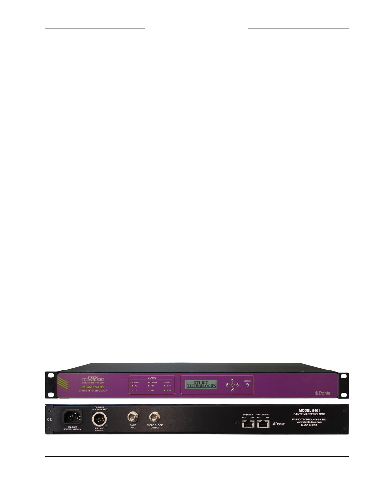
The Model 5401 Dante Master Clock
provides precise timing signals for applications that utilize the Dante® audio-overEthernet media networking technology. The
unit implements a high-performance IEEE
1588 precision time protocol (PTP) server,
compatible with the requirements of Dante
and capable of simultaneously supporting the timing needs of up to hundreds of
Dante-compatible devices. As expected, the
Model 5401 provides the PTP v1 (IEEE®
1588-2002) compatibility that’s required by
Dante. In addition, the unit supports PTP
v2 (IEEE 1588-2008) for AES67 applications. A word clock output provides a timing
reference for use by external devices. The
Model 5401 also generates up to eight sinewave audio tones on Dante transmit (output) channels, useful during audio network
installation, maintenance, and operation.
A sync input connection allows the Model
5401’s internal oscillator to synchronize
with a variety of timing reference signals.
The Model 5401 is suitable for use in fixed
and mobile broadcast facilities, post-production studios, commercial and educational theater environments, and entertainment
applications. Only power and one or two
Ethernet network connections are required
for full operation. Using Dante’s inherent
capabilities two Model 5401 units can
serve in primary and secondary master
clock roles for redundant operation.
An integral web server allows fast and
flexible monitoring and configuration of
the Model 5401’s master clock, tone
generation, and networking performance.
Front-panel indicators, an LCD display,
and pushbutton switches provide personnel with direct access to key operating parameters. Updating of the Model
5401’s operating software can be easily
performed using the integrated FTP (filetransfer protocol) client. The unit’s dual
Gigabit Ethernet (“GigE”) network interfaces allow support for redundant Dante
operation. All software files and configuration parameters are stored in non-volatile
memory. The Model 5401 can be powered
by 100-240 V, 50/60 Hz mains or a source
of 12 volts DC. The lightweight enclosure
mounts in one space (1U) of a standard
19-inch rack.
Applications
Applications for the Model 5401 include
broadcast facilities, college and university
audio networks, arenas, stadiums, and
corporate installations — virtually any
application where substantial numbers
of Dante-compatible devices are utilized.
The Model 5401 will serve as a stable and
Figure 1. Model 5401 Dante Master Clock front and back views
Model 5401 User Guide Issue Preliminary 4, May 2018
Studio Technologies, Inc. Page 5
Page 6

Model 5401
DANTE MASTER CLOCK
consistent master clock for the entire Dante
“network.” And, as expected, the Model 5401
is compatible with all Dante devices, no
matter what their primary function or manufacturer. Applications that utilize devices
compatible with AES67 will also benefit from
the Model 5401’s resources.
Why a Dedicated Dante Master
Clock?
With Dante ubiquitous in fixed and mobile
facilities of all sizes and types, the need
arose for a cost-effective, purpose-designed,
dedicated master clock. While an inherent
strength of Dante networking is its carefully
implemented use of IEEE 1588 to ensure
that all connected devices maintain a common timing reference, the actual performance can vary widely depending on the
specific Dante devices in use and the overall
number of devices on a network. There are
many Dante-compatible devices that can
provide adequate basic performance as a
master clock, but with the Model 5401 networked audio systems get the benefits of a
high-performance “grandmaster” PTP server,
along with additional unique capabilities.
The unit’s feature set, along with the associated internal hardware and software, was
designed to provide optimum performance,
flexibility, and system integrity.
Timing Sources
The Model 5401 can provide excellent
master clock performance using its accurate
and stable internal oscillator, which is temperature-controlled and exceeds the performance of standard Dante devices by at least
an order of magnitude. While its standalone
performance is excellent, the Model 5401
can also be “locked” to a variety of external signals for integration into facilities that
include a master timing reference. Compatible signals include word clock, video reference, and 10 MHz.
A word clock signal is often used as a timing reference in audio-only facilities. Several word clock rates, including 48 and 96
kHz, are compatible with the Model 5401’s
sync input. Video reference (“sync”) signals
are found in most broadcast and post-production facilities. The Model 5401 supports
the most-common video format/rate combinations including “black burst,” bi- and
tri-level HD, and several that are specifically
intended for 4K applications. Industrial and
commercial facilities often utilize a GPSdisciplined source of 10 MHz as a timing
reference. This sine-wave signal is directly
compatible with the unit’s sync input.
Word Clock Output
The Model 5401 generates a precise word
clock output signal that can be used as
a timing reference for related equipment.
It’s specifically intended for “locking” audio
equipment in applications that have Dante
equipment whose timing reference signals
are provided by a Model 5401. In this way
all devices will share a common timing
reference.
The word clock output rate can be selected
to be 44.1, 48, 88.2, or 96 kHz. The underlying timing source for the word clock output is derived from the Model 5401’s main
timing source. As previously reviewed, the
internal oscillator, if desired, can be “locked”
to an external source. The main timing
source is divided and processed by the
Model 5401’s logic circuitry to create
the highly stable word clock output. This
ensures that the word clock output is
synchronized with the unit’s PTP server
functionality.
Issue Preliminary 4, May 2018 Model 5401 User Guide
Page 6 Studio Technologies, Inc.
Page 7

Model 5401
DANTE MASTER CLOCK
Audio Reference Signals
The Model 5401 generates eight sinewave audio reference signals for general-purpose use. They are individually
configurable in level and frequency. These
audio “tones” are available on the Model
5401’s Dante transmitter (output) channels
and can be connected, using the Dante
Controller application, to Dante receivers
(inputs) on related equipment. The flexibility of the available routes (Dante “subscriptions”) between all Dante devices on a
network allows the reference signals to be
used for a variety of purposes. Configuration choices allow the frequency and level
of the sine-wave signals to be optimized
for specific applications.
Master Clock Support for
Dante Networks
A core part of the technology underlying
Dante audio-over-Ethernet networking
ensures that all connected devices follow
a common timing reference. This is accomplished using the industry-standard
IEEE 1588-2002 precision time protocol
(PTP v1). Any connected Dante device
can be used as a master clock; there is
no requirement that a dedicated master
clock device be utilized to realize adequate
performance. However, the actual performance can range widely depending on the
specific Dante devices available and the
overall number of Dante devices on the
network.
Many Dante devices utilize the 2- or 4channel Ultimo™ integrated circuit to
implement Dante connectivity. While
Ultimo devices will fully support Dante
audio transport they are not well suited
to serve as a master clock. Ultimo’s PTP
performance is limited and does not have
the ability to synchronize with an external
timing reference. Other Dante devices use
the Brooklyn II module to support Dante
connectivity. In many cases these devices
can provide good basic performance as
a master clock including some that allow
connection of an external source of word
clock.
However, problems and limitations may
arise when these devices are called upon
to perform “double duty,” serving both a
primary function (such as analog-to-Dante
interfacing or audio signal processing) as
well as acting as a master clock. This is
understandable as the main purpose of
these devices is to serve a function other
than as a master clock. Timing related
features, such as allowing connection of
a video bi- or tri-level sync signal is rarely,
if ever, supported. And PTP performance
can degrade when the computing power of
a device is intended primarily for handling
and manipulating digital audio signals. This
can lead to the required PTP resources
being in short supply when the number of
Dante devices that need timing messages
moves into the hundreds. Also, firmware
updates, cabling changes, and other maintenance tasks typically associated with a
general-purpose Dante audio device would
impact the master clock functionality for an
entire installation.
The Model 5401 was specifically designed
to support a Dante-based audio system’s
master clock requirements. The unit’s generation of audio tones and implementation
of the word clock output utilize hardware
that is separate from that associated with
PTP functionality. As such, this secondary functionality will not interfere with PTP
operation. Unlike a general-purpose audio
device, once mounted in an equipment
Model 5401 User Guide Issue Preliminary 4, May 2018
Studio Technologies, Inc. Page 7
Page 8

Model 5401
DANTE MASTER CLOCK
rack and the required interconnections
are made, the Model 5401 will perform its
tasks without risk of interruption due to
conflicting resource demands.
Overall Networking Capability
Using the Dante Controller application
program the Model 5401’s two Gigabit
Ethernet ports can be selected to operate
in one of three modes: Switched, Redundant, and Pri Dante/Sec Mgmt. In the
Switched mode a single Ethernet connection to either of the Model 5401’s Ethernet ports will provide Dante master clock
functionality as well as access to the Model
5401’s management web pages. The
remaining Model 5401 Ethernet port will
provide network “loop-through” capability
and can be used to interface with another
piece of Ethernet-connected equipment.
In the Redundant mode two independent
Ethernet connections are made to the
Model 5401’s Ethernet ports, enabling
Dante’s redundant network capability.
In this mode the Model 5401’s primary
Ethernet port will provide access to the
management web pages. In the Pri Dante/
Sec Mgmt mode, the Model 5401’s primary
Ethernet port will be used by the network
associated with Dante while the secondary
Ethernet port will be used to access the
unit’s management web pages. This allows
separate networks to be maintained for
Dante and maintenance and configuration
purposes.
Operating Power
The Model 5401 allows an AC mains
source of 100-240 V, 50/60 Hz to be directly connected. It can also be DC powered
using a 10-18 volt source that is connected
via a broadcast-standard 4-pin XLR connector. If both AC and DC power sources
are connected the unit will be powered by
the AC mains supply. Only if the AC mains
source fails will a load be placed on the DC
source. This allows a source of DC, typically an external power supply or broadcast-style battery, to serve in a backup
capacity. With this arrangement normal
operation can continue even if AC mains
power is lost.
Future Capabilities
The Model 5401’s main and logic (FPGA)
embedded software (firmware) can to be
updated by way of its Ethernet network
connection and the internet. Multiple versions of firmware are used to support
the Dante interface hardware, user management menus, and audio generation
capabilities. Each can be independently
updated as required.
Installation
— Pending —
Configuration
Sync Settings Menu
Force Preferred Master
This is a configurable field with two
choices: Disabled or Enabled. The default
factory selection is Enabled; restoring the
Model 5401’s factory defaults will return
the selection to Enabled.
This function impacts how the Model 5401
will control a Dante network’s selection of
which device is going to serve as the master clock. As the main reason for the Model
5401’s existence is to serve as a master
clock, in most cases the unit should serve
Issue Preliminary 4, May 2018 Model 5401 User Guide
Page 8 Studio Technologies, Inc.
Page 9

Model 5401
DANTE MASTER CLOCK
in that role. By forcing the Model 5401 to
be a preferred master it helps to ensure
optimal Dante network operation. Users
of the Dante Controller application will not
be able to accidentally disable the Model
5401 as a preferred master. One can see
exactly what is meant by the term “force
preferred master” by unchecking the Model
5401’s preferred master check box in
Dante Controller. After a short interval the
box will automatically return to the enabled
(checked) state.
How the Model 5401 handles forcing the
Dante network to master clock operation
and, if applicable, supporting an external
clock input is not trivial. Reviewing some
of the details can provide valuable insight:
If the Model 5401’s clock source is configured for Dante the Model 5401 will always
force the enable sync to external selection
in Dante Controller to be off (unchecked).
If the Model 5401’s clock source is configured for Internal then the Model 5401
will always force Enable Sync to External
in Dante Controller to be on (checked) as
long as the Model 5401 is acting as primary master, secondary master, or AES67
master. If the Model 5401’s clock source is
configured for Sync Input the Model 5401
will always force the enabled sync to external in Dante Controller to be on (checked).
Clock Source
This is a configurable field with three
choices: Internal, Sync Input, or Dante.
The default factory selection is Internal;
restoring the Model 5401’s factory defaults
will return the selection to Internal.
This setting determines which timing
source is used by the Model 5401’s circuitry as its own “master” timing reference.
This is the clock source that will be used
by the Model 5401’s PTP server circuitry,
the “heart” of the Model 5401’s support of
related Dante devices. When Internal is
selected the Model 5401’s temperaturestabilized, high-performance crystal oscillator is utilized. This will provide excellent
timing accuracy and long-term consistent
performance. This source is far superior
to that provided by other standard Dante
devices. This is the correct choice if a
high-quality external reference signal is
not going to be connected.
When Sync Input is selected the Model
5401’s external sync input connection will
be active. Using a BNC connector, located
on the Model 5401’s back panel, an external source of word clock, video reference,
or 10 MHz sine wave can be connected.
Circuitry with the Model 5401 will “lock”
(synchronize) the internal timing signals
to the externally provided reference signal.
This is the recommended operating mode
if a precision external reference is available. For example, in facilities that have
equipment that supports video it’s typical
to have a high-end master timing generator. And in audio facilities a “master” source
of word clock may be available. In industrial or commercial settings a GPS receiver
may be provided as a source of highprecision 10 MHz. But be aware that it is
possible that an externally available reference signal may not be as “good” as the
Model 5401’s internal oscillator. If that is
the case then the internal source should
be utilized. Other devices in a facility can
then “lock” to the Model 5401’s word clock
output. (This is available by way of a BNC
connector located on the Model 5401’s
back panel.)
Model 5401 User Guide Issue Preliminary 4, May 2018
Studio Technologies, Inc. Page 9
Page 10

Model 5401
DANTE MASTER CLOCK
Selecting Dante will instruct the Model
5401 to use the clock signal from its Dante
interface circuitry as the timing source
for the PTP server. The Dante interface
circuitry will either use its internal crystal
oscillator or synchronize to another Dante
device on the network. The clock source
the Model 5401’s Dante interface uses will
depend on a setting in the Dante Controller
application. The Model 5401 includes the
choice of Dante as a clock source only for
trouble-shooting or other factory-directed
activities. It’s not expected that this selection will ever be used during normal Model
5401 operation. By selecting Dante the
excellent timing performance that the internal oscillator can provide or the benefits
gained from synchronization with a “house”
timing reference would not be utilized.
Sync Input Type
This is a configurable field with three choices: Word Clock, Video, or 10 MHz. The
default factory selection is Word Clock;
restoring the Model 5401’s factory defaults
will return the selection to Word Clock.
If the Model 5401’s clock source has been
selected to Sync Input the type of connected source must be defined. If Word Clock
is selected then a square wave source
with a rate of 44.1 kHz, 48 kHz, 88.2 kHz,
or 96 kHz can be connected. For proper
operation the nominal level of the word
clock source must be 5 volts DC. Also, the
connected word clock source must match
the displayed current Dante sample rate.
This is a bit of a “chicken or the egg” situation since it can be confusing as to who
is supposed to control the sample rate and
who is supposed to follow the sample rate!
The Dante Controller software application
should be used to select the desired Model
5401 sample rate. This is the sample rate
desired for the eight channels of audio
tone generator (Model 5401 Dante transmitter channels). In most applications this
will be 48 kHz. It’s possible that in some
audio-only applications 96 kHz will be
selected. Once the desired sample rate
has been selected and/or confirmed, an
external word clock source of the same
rate should be connected. If the available
external word clock source has a rate different than the current Dante sample rate
then a review of the entire application must
be performed and a common rate selected.
If Video is selected for the sync input type
then a wide range of bi- and tri-level video
reference signals can be connected to
the sync input BNC connector. The Model
5401’s circuitry will automatically decode
the most common format/rate combinations. These include ubiquitous “black
burst” signals as well as signals intended
to support 4K video applications. Refer to
Appendix A at the end of this guide for a
detailed list of compatible video sources.
If a choice of sync sources is available
the factory recommends that a source of
word clock be utilized. This is because the
Model 5401’s clock circuitry has to perform
the least amount of processing with a word
clock input signal as compared to that required for a video or 10 MHz signal.
Sync Input Termination
This is a configurable field with two
choices: Off and On. The default factory
selection is On; restoring the Model 5401’s
factory defaults will return the selection
to On.
If desired, the Model 5401 can apply a
terminating impedance to the sync input
connection. The need for an input source
to be terminated, or not, will depend on the
Issue Preliminary 4, May 2018 Model 5401 User Guide
Page 10 Studio Technologies, Inc.
Page 11

Model 5401
DANTE MASTER CLOCK
source of the external sync signal. Typically a source of sync should have one (and
only one) termination applied. The source
can generally be shared (“bused”) to multiple devices with the last connection on the
connection string applying an appropriate
termination.
If sync input termination is configured for
Off then the sync input’s impedance will be
greater than 100 k ohms. If the sync input
termination is selected to On and the sync
input type is selected for Word Clock or
Video the termination impedance will be
75 ohms. If 10 MHz has been selected
as the sync input type then a termination
impedance of 50 ohms will be applied.
Sync Input Failover Source
This is a configurable field with two choices: Internal or Dante. The default factory
selection is Internal; restoring the Model
5401’s factory defaults will return the selection to Internal.
This configuration choice applies only if
the Model 5401 has been configured to
use the sync input. It specifies which clock
source should be used by the Model 5401
if a valid sync source is not connected to
the sync input. If Internal is selected then
the precision crystal oscillator will be utilized as the master clock source should a
valid signal not be connected to the sync
input. If Dante is selected then the clock
source derived from the Dante interface
will be used.
From a performance standpoint it’s preferable to select Internal. This ensures
that the best clock performance can be
obtained should a valid external sync
source not be present (sync input status
unlocked). However, selecting Dante would
allow an interesting alerting feature to
become active. In the Dante Controller application a device, such as the Model 5401,
that has been selected as the preferred
master with an external source allowed will
have an error condition occur if the Dante
interface doesn’t detect an external reference being applied. And losing the external
reference is what the Model 5401’s circuitry will do should Dante be selected as the
failure source. In this way a Dante network
user could be alerted to an issue with the
Model 5401 should it lose its very important external sync source.
Getting an error condition reported in
Dante Controller is probably not terribly
important. The sync LED on the Model
5401’s front panel will also offer a clear
indication of a loss of an external sync
signal. The LED will typically slowly flash
green when the Model 5401 is functioning
correctly as the clock master for the Dante
network. However, should the unit be
configured to use an external sync signal
and a valid one is not present, the sync
LED will flash orange to indicate the loss
of lock to the sync input. In addition, the
display will provide a text indication of this
condition.
Sync Input Status
This is a display-only field that can show
---, Unlocked, or Locked.
This field reflects the status of the Model
5401’s sync input circuitry. If the Model
5401’s clock source has not been selected
for Sync Input then the sync input status
field will display ---. This simply indicates
that the Model 5401 has not been configured to utilize an external sync source so
there is no status associated with it.
Unlocked will be displayed if the sync
input has been selected as the clock
Model 5401 User Guide Issue Preliminary 4, May 2018
Studio Technologies, Inc. Page 11
Page 12

Model 5401
DANTE MASTER CLOCK
source but either no signal is connected or
a non-compatible signal is connected. A
non-compatible signal would include a sync
input type being selected for Word Clock
and then a word clock signal at a different
rate than the current Dante sample rate
being connected. For example, the situation where the current Dante sample rate is
48 kHz but the connected word clock signal is 96 kHz. Probably the most common
non-compatible signal would be a situation
where a video reference signal is connected
to the sync input but the sync input type
was left at the default (Word Clock) rather
than being selected for Video.
Locked will be displayed when a signal
connected to the Model 5401’s sync input
is serving as the master timing reference.
If the clock source configuration has been
selected for External this is the desired
condition. If Locked does not display then
standard troubleshooting should be performed to remedy the issue. In most cases
the problem will be resolved by ensuring
that the sync input type configuration and
the actual connected sync source are the
same.
Detected Sync Input Format
This is a display-only field that can show ---,
Error, 44.1 kHz, 48 kHz, 88.2 kHz, 96 kHz,
one of the video format/rate combinations,
or 10 MHz.
This field reflects the operation of the
Model 5401’s sync input circuitry. If the
clock source is not set for External then
the circuitry is not operational and --- will
display. If External is selected then the
field will display either Error or a detected
rate. Error will display if the connected
source doesn’t match the selected sync
input type. For example, if Word Clock has
been selected as the sync input type but
a video sync signal has been connected.
The detected rate will be displayed whenever the sync input status is locked. If this
is a word clock signal then one of the four
compatible rates will be displayed. If this is
due to a video source being connected then
the actual rate/format characteristics will
be displayed. The compatible rate/format
combinations are listed in Appendix A of this
Guide. If locked is due to a 10 MHz signal
being recognized then 10 MHz will display.
Current Dante Sample Rate
This is a display-only field that can show
44.1 kHz, 48 kHz, 88.2 kHz, or 96 kHz.
This field displays the Model 5401’s currently selected sample rate as used by the
Model 5401’s Dante transmitter (output)
channels. The transmitter channels, as of
the initial firmware release, provide eight
unique tone outputs labeled Tone01 through
Tone08. From the factory the Model 5401’s
sample rate is selected to be 48 kHz.
Changes to the sample rate are made using
the Dante Controller software application.
Restoring the Model 5401’s factory defaults
will not change the sample rate setting.
Submit
The Submit button is located on the bottom
of the Sync Settings menu page. For any
changes made to fields on the Sync Settings page to be saved and acted upon the
Submit button must be pressed.
Identify Device
The Identify Device button is located in the
upper-left corner of the Sync Settings main
page, directly below the Dante device name
display. Pressing the Identify Device button will cause the associated Model 5401
Issue Preliminary 4, May 2018 Model 5401 User Guide
Page 12 Studio Technologies, Inc.
Page 13

Model 5401
DANTE MASTER CLOCK
to flash its green backlight associated with
the display five times.
Audio Generator Menu
The Model 5401’s audio generator function is capable of creating eight precision
sine-waves signals (“tones”) with independent frequency and level configuration.
The frequency range is 1 to 22000 hertz
(Hz) and the level range is –99 to 0 dBFS.
The output signals have default names of
Tone01 through Tone08. It’s expected that
most applications will only use a few of the
tones. But having eight output channels
provides flexibility in creating a range of
signals with various frequency and level
combinations. These can be used for a
range of applications including identifying
individual channels in a multi-channel arrangement, e.g., stereo, 5.1, or 7.1.
Level (dBFS)
These eight fields display the level of the
Model 5401’s eight sine-wave outputs.
The output level for each of the eight audio
generator output channels is independently
adjustable over a range of –99 to 0 dBFS.
Enter the desired level in full dBFS with a
hyphen as the prefix to indicate less than
full scale. In applications that comply with
the SMPTE® audio standards the typical
nominal level will be –20 dBFS which can
be thought of as 20 dB less than full scale
or digital 0. In EBU applications the typical nominal level will be –18 dBFS. Some
applications may benefit from a sine wave
test tone that’s 12 dB less than the reference level. This would equate to configuring an output to –34 dBFS (SMPTE) or
–32 dBFS (EBU). These would typically
be associated with a 1000 Hz.
Frequency (Hz)
These eight fields reflect the Model 5401’s
currently selected sine-wave generator
frequencies. For each channel enter the
desired frequency in full hertz. Don’t use
a suffix such as k or kHz, nor enter a
comma or period to delineate thousands.
Entering 1001 would be correct while
1,001 or 1.001 k would not be acceptable.
The default tone frequencies were selected
in hundreds of hertz with the first digit
matching the channel number: 100, 200,
300, etc. This can be useful when checking a series of channels as this pattern can
be easily recognized either by ear or using
equipment that can display the frequency
in text. Some applications may need the
common 1000 or 10000 Hz reference sine
wave tones and there’s no problem configuring these if desired.
The default tone levels were selected in a
pattern that could help identify a specific
channel. Channel Tone01 has a default
level of –21 dBFS with the value of 1 being
selected to reflect the channel number.
Each subsequent channel then reduces its
level by 1 dB. So, for example, the second
channel, Tone02, has a level of –22 dBFS.
While these level steps may not be readily
discernible to human ears most test equipment or metering could easily be used to
identify specific channels.
Submit
The Submit button is located on the bottom
of the Audio Generator menu page. For
any changes made to fields on the Audio
Generator page to be saved and acted
upon the Submit button must be pressed.
Model 5401 User Guide Issue Preliminary 4, May 2018
Studio Technologies, Inc. Page 13
Page 14

Model 5401
DANTE MASTER CLOCK
Identify Device
The Identify Device button is located in the
upper left corner of the Audio Generator
main page, directly below the Dante device
name display. Pressing the Identify Device
button will cause the associated Model
5401 to flash its green backlight on the
display five times.
Network Configuration Menu
Dante IP Addresses
Primary
This is a display-only field that shows the
IP address associated with the Model
5401’s primary Dante data path. It will
show either No Ethernet Link or an IP
address. The IP address displayed in this
field is not the IP address associated with
the Model 5401’s internal management
web server. The 32-bit IP v4 address is
displayed in what’s known as dot-decimal
notation.
How the IP address is determined depends
on the Model 5401’s network configuration setting as performed using the Dante
Controller application. The IP address
can be established automatically using a
DHCP server or the IPv4 link-local protocol. An IP address assigned to the primary
Dante port by link-local will have a format
of 169.254.x.x. The primary IP address can
also be set to a manual (static or fixed) IP
address using Dante Controller.
If the network configuration is selected in
Dante Controller for Switched (the factory
default) then the primary Dante IP address
will be associated with a network connection made to either the primary or the
secondary RJ45 connections on the Model
5401’s back panel. If the network configuration is selected for Redundant or
Pri Dante/Sec Mgmt then the primary
Dante IP address will be associated with
the RJ45 connection labeled Primary on
the Model 5401’s back panel. No Ethernet
Link will display if a valid Ethernet connection has not been made with the primary
RJ45 jack.
If the Model 5401’s network configuration
in Dante Controller is selected for Switched
ensure that only one of the RJ45 connections on the back panel is connected to the
LAN associated with the Dante devices.
The other RJ45 connection can be used
to interconnect with another piece of networked equipment. But having both of the
Model 5401’s RJ45 connections routed to
ports on the same LAN will typically “crash”
the network!
Secondary
This is a display-only field that shows the
IP address associated with the Model
5401’s secondary Dante data path. It will
show Disabled, No Ethernet Link, or an IP
address. The IP address displayed in this
field is not the IP address associated with
the Model 5401’s internal management
web server.
What is displayed and how a displayed
IP address is determined depends on
the setting of the Model 5401’s network
configuration using the Dante Controller
application. If the network configuration
is selected for Switched or Pri Dante/Sec
Mgmt then a secondary Dante IP address
will never be active and Disabled will be
displayed.
If the network configuration is selected
for Redundant then the secondary Dante
IP address will be displayed. This is the
Ethernet connection that is associated with
RJ45 connection labeled Secondary on the
Issue Preliminary 4, May 2018 Model 5401 User Guide
Page 14 Studio Technologies, Inc.
Page 15

Model 5401
DANTE MASTER CLOCK
Model 5401’s back panel. The IP address
can be established automatically using a
DHCP server or the IPv4 link-local protocol.
An IP address assigned to the secondary
Dante port by link-local will have a format
of 172.31.x.x. The secondary IP address
can also be set to a manual (static or fixed)
number using the Dante Controller application. No Ethernet Link will display if a valid
Ethernet connection has not be made with
the secondary RJ45 jack.
Management Addresses
MAC Address
This is a display-only field that shows the
Model 5401’s MAC (media access control)
address. This is a unique hardware identification number that is assigned to each
specific Model 5401. No two Ethernetconnected devices should ever share a
MAC address.
Current IP Address
This is a display-only field that shows the IP
address associated with the Model 5401’s
internal management web server. This
address can be assigned automatically
via DHCP or IPv4 link-local. It can also be
manually assigned with a fixed or static IP
address. The Current IP Address is not associated with the Model 5401’s primary or
secondary Dante data connections.
If the Model 5401’s network configuration
is selected in Dante Controller for Switched
(the factory default) then the management
IP address will be associated with a network connection made to either the primary
or secondary RJ45 connections on the
Model 5401’s back panel. If the network
configuration is selected for Redundant
then the IP address will be associated with
the network connection made to the RJ45
connection labeled Primary on the Model
5401’s back panel. If the network configuration is selected for Pri Dante/Sec Mgmt
then the IP address will be associated
with network connection made to the RJ45
connection labeled Secondary on the
Model 5401’s back panel.
As previously mentioned, if the Model
5401’s network configuration in Dante
Controller is selected for Switched ensure
that only one of the RJ45 connections on
the back panel is connected to the LAN associated with the Dante devices. The other
RJ45 connection can be used to interconnect the same LAN with another piece of
networked equipment. But having both of
the Model 5401’s RJ45 connections routed
to ports on the same LAN will typically
“crash” the network!
IP Address Configuration
This is a configurable field with two choices: Automatic and Manual. The default
factory selection is Automatic. To minimize
the chance of losing access to the internal management web server restoring
the Model 5401’s factory defaults will not
change the currently selected choice.
This configuration impacts how the Model
5401 obtains the IP address that is used
for accessing the Model 5401’s management web server and associated menu
pages. This setting has no impact on how
the Model 5401 obtains the primary and
secondary IP addresses associated with
the Dante Ethernet connections.
Selecting the Automatic setting will cause
the Model 5401 to use DHCP or IPv4
link-local to establish the IP address of the
Model 5401’s management port. With this
setting upon establishing a link to the appropriate Model 5401 RJ45 jack the DHCP
protocol will request an IP address and
Model 5401 User Guide Issue Preliminary 4, May 2018
Studio Technologies, Inc. Page 15
Page 16

Model 5401
DANTE MASTER CLOCK
related parameters. If obtaining an IP address by way of the DHCP protocol is not
successful then the IPv4 link-local protocol
will be used. If an IP address that has the
format of 169.254.x.x displays as the current IP address then it was assigned using
IPv4 link-local. Even if the IP address was
established using link-local the DHCP protocol will stay active. Approximately every
60 seconds the Model 5401’s firmware
will check for the presence of a DHCP
server. If one becomes available then an
IP address will be requested and, when
obtained, will automatically be used, replacing the IP address that was previously
established by link-local.
The Manual setting allows the desired
IP address and related parameters to
be manually entered. This can be useful
when a fixed addressing scheme has been
established. In this way a static IP address
can be entered along with the other important network parameters.
When selected for Automatic the fields for
manual IP address, subnet mask, gateway
IP address, and DNS IP address will be
“grayed out” (will have a gray background)
to indicate that their values cannot be
manually changed. In this condition they
are display-only. Changing between Auto-
matic and Manual and vice-versa will not
impact the values stored in the manual IP
address, subnet mask, gateway IP address, and DNS IP address fields.
Manual IP Address
This field is grayed out and will not display
any text when the IP address configuration
mode is selected for Automatic. When the
IP address configuration is selected
for Manual this field will display the IP
address that is stored in the Model 5401.
This is the IP address that is currently
being used, or will be used at the time of
the next Ethernet connection reboot. It is
the IP address that allows access to the
Model 5401’s management web server
and associated menu pages. It has nothing
to do with the IP address(es) associated
with the Dante port(s). The manual IP address can be modified as desired to meet
the requirements of the application. After
entering an IP address using the standard dot-decimal notation format (4 octets
separated by dots) the Submit button must
be pressed for the changes to be stored.
Restoring the Model 5401 default values
will not change the stored IP address. A
system reboot is required for the revised
manual IP address to be utilized.
Subnet Mask
This field is grayed out when the IP address configuration mode is selected for
Automatic. This field will be display-only
in this instance and will display an IPv4
subnet mask in dot-decimal notation (4
octets separated by dots) if the current IP
address and related network parameters
were obtained by way of DHCP. This is
the subnet mask that is being used by the
internal management web server. If IP configuration mode is selected for Automatic
and the current IP address was obtained
by way of link-local then the associated
subnet mask of 255.255.0.0 will be shown
in this field.
When the IP address configuration is
selected for Manual the field will not be
grayed out. In this situation the stored
subnet mask will be displayed and can be
modified as desired to meet the requirements of the application. The displayed
value is the subnet mask that is currently in
use or will be used at the time of the next
Ethernet connection reboot. After entering
Issue Preliminary 4, May 2018 Model 5401 User Guide
Page 16 Studio Technologies, Inc.
Page 17

Model 5401
DANTE MASTER CLOCK
an IP address using the standard dotdecimal notation format (4 octets separated
by dots) the Submit button must be pressed
for a change to be stored. A system reboot
is required for the revised subnet mask
value to be utilized. Restoring the Model
5401 default values will not change the
stored subnet mask value.
Gateway IP Address
This field is grayed out when the IP address configuration mode is selected for
Automatic. This field will be display-only in
this instance and will display an IPv4 gateway IP address in dot-decimal notation (4
octets separated by dots) if the current IP
address and related network parameters
were obtained by way of DHCP. This is the
gateway IP address that is being used by
the Model 5401’s management web server.
If the IP configuration mode is selected for
Automatic and the current IP address was
obtained by way of link-local no gateway IP
address will be shown in this field. This is
because no gateway IP address is associated with link-local.
When the IP address configuration is selected for Manual the field will not be grayed
out. In this situation the stored gateway IP
address will be displayed and can be modified as desired to meet the requirements
of the application. The displayed value is
the gateway IP address that is currently in
use, or will be used at the time of the next
Ethernet connection reboot. After entering a
gateway IP address using the standard dotdecimal notation format (4 octets separated
by dots) the Submit button must be pressed
for a change to be stored. A system reboot
is required for the revised gateway IP address to be utilized. Restoring the Model
5401 default values will not change the
stored gateway IP address value.
DNS IP Address
This field is grayed out when the IP address configuration mode is selected for
Automatic. This field is display-only in this
instance and will display an IPv4 DNS IP
address in dot-decimal notation (4 octets
separated by dots) if the current IP address and related network parameters
were obtained by way of DHCP. This is the
DNS IP address that is being used by the
Model 5401’s management web server.
If IP configuration mode is selected for
Automatic and the current IP address was
obtained by way of link-local no subnet
mask will be shown in this field. This is
because no DNS IP address is associated
with link-local.
When the IP address configuration is
selected for Manual the field will not be
grayed out. In this situation the stored DNS
IP address will be displayed and can be
modified as desired to meet the requirements of the application. The displayed
value is the DNS IP address that is currently being used, or will be used at the time of
the next Ethernet connection reboot.
In most cases the Model 5401’s default
DNS IP address will be appropriate. It is
8.8.8.8 which is one of the two IPv4 recursive public name servers provided by
Google®. But there’s no issue entering a
revised DNS IP address. Once it is en
tered, using the standard dot-decimal notation format (4 octets separated by dots),
the Submit button must be pressed for a
change to be stored. A system reboot is required for the revised gateway IP address
to be utilized. Restoring the Model 5401
default values will not change the stored
gateway IP address.
Model 5401 User Guide Issue Preliminary 4, May 2018
Studio Technologies, Inc. Page 17
Page 18

Model 5401
DANTE MASTER CLOCK
Submit
The Submit button is located on the bottom
of the Network Configuration menu page.
For any changes made to fields on the
Network Configuration page to be saved
and acted upon the Submit button must be
pressed.
Identify Device
The Identify Device button is located in the
upper-left corner of the Network Configuration main page, directly below the Dante
device name display. Pressing the Identify
Device button will cause the associated
Model 5401 to flash its green backlight associated with the display five times.
Operation
— Pending —
Technical Notes
— Pending —
Issue Preliminary 4, May 2018 Model 5401 User Guide
Page 18 Studio Technologies, Inc.
Page 19

Model 5401
DANTE MASTER CLOCK
Specifications
Applications:
High-performance master clock for Dante audio-overEthernet applications. Also supports AES67-2013
applications. In addition provides audio reference
signals (tones) for general-purpose use and a
precision word clock sync output.
Precision Time Protocol (PTP) Support:
IEEE® 1588-2002 Version 1 (v1) for Dante; IEEE
1588-2008 Version 2 (v2) for AES67-2013
Timing Reference:
Source: internal time-base, external sync input, or via
an existing Dante network, selectable
Internal Time Base:
Type:
24.576 MHz temperature-stabilized crystal
oscillator
Initial Accuracy:
Long-Term Accuracy:
per year
Temperature Stability:
0-50 degrees C
Sync Input:
Compatible Sources: word clock, bi-level video,
tri-level video, 10 MHz
Termination:
clock or video), or high Z (unterminated), selectable
Word Clock
nominal unloaded, 44.1, 48, 88.2, or 96 kHz
o Characteristics: bi- or tri-level, 1 Vpp into
Vide
75 ohm load
10 MHz Characteristics: sine wave, 3 Vpp into
50 ohm load
Word Clock Output:
Type:
square wave
Rate: 44.1, 48, 88.2, or 96 kHz, selectable using
Dante Controller application
Impedance: 75 ohms
Amplitude: 5 Vpp, measured unterminated
Jitter: measurement pending
Network Audio Technology:
Type:
Dante audio-over-Ethernet
AES67-2013 Support: yes; selectable on/off
Dante Domain Manager (DDM) Support: yes
2 ppm (parts-per-million)
1 ppm (parts-per-million)
±280 ppb (parts-per-billion),
50 ohms (10 MHz), 75 ohms (word
Characteristics: square wave, 5 Vpp
Ethernet Interface Configuration: Switched,
Redundant, or Pri Dante/Sec Mgmt
Clock Source: follows overall Model 5401
configuration
Bit Depth: 24
Sample Rate: 44.1, 48, 88.2, or 96 kHz, selectable
using Dante Controller application
Number of Dante Transmitter (Output) Channels:
Number of Dante Flows: 32
Audio Reference Signals:
continuous sine-wave signals on Dante
Type:
transmitter (output) channels
Number of Channels: 8
Frequency: 1 Hz to 22 kHz, individually configurable
in 1-Hz steps
Amplitude: 0 to –99 dBFS, individually configurable
in 1-dB steps
Distortion (THD+N): <0.0001% (<–121 dB),
measured at 1 kHz, –1 dBFS
Network Interfaces: 2, primary and secondary
Type: 1000BASE-T (Gigabit Ethernet (“GigE”)) per
IEEE 802.3ab (100 Mb/s also supported but not
recommended for optimal performance)
NIC Status LEDs: one link and one activity for each
Ethernet interface
Software Updating: internal FTP client supports
updating of application, main FPGA, and sync FPGA
software; process requires unrestricted access to the
internet or a local FTP server
Front-Panel Display: LCD with LED backlighting
Front-Panel LEDs: 6, dual-color
Functions: provides indication of condition of incom-
ing AC and DC power, status of Dante connections on
Ethernet interfaces, and status of Dante connectivity
Power Sources:
AC Mains: 100 to 240 V, 50/60 Hz, 5 W maximum
DC: 10 to 18 V, 0.5 A max
Connectors:
Sync Input, Word Clock Output:
61169-8 Annex A
Ethernet: 2, RJ45
AC Mains Input: 3-blade, IEC 320 C14-compatible
(mates with C13)
DC Input: 4-pin male XLR (pin 1 negative, pin 4
positive)
BNC, per IEC
8
Model 5401 User Guide Issue Preliminary 4, May 2018
Studio Technologies, Inc. Page 19
Page 20

Model 5401
DANTE MASTER CLOCK
Environmental:
Operating Temperature:
(32 to 122 degrees F)
Storage Temperature:
(–40 to 158 degrees F)
Humidity: 5 to 95%, non-condensing
Altitude: not characterized
Dimensions (Overall):
19.00 inches wide (48.3 cm)
1.72 inches high (4.4 cm)
7.9 inches deep (20.1 cm)
Mounting: one space (1U) in a standard 19-inch rack
0 to 50 degrees C
–40 to 70 degrees C
Weight:
Specifications and information contained in this
User Guide subject to change without notice.
3.0 pounds (1.4 kg)
Issue Preliminary 4, May 2018 Model 5401 User Guide
Page 20 Studio Technologies, Inc.
Page 21
Model 5401
DANTE MASTER CLOCK
Appendix A—Sync Input Sources
The Model 5401’s sync input has been tested and confirmed for correct operation with the
following sync signals:
Word Clock: Square wave signal with rate of 44.1, 48, 88.2, or 96 kHz
10 MHz: Sine wave signal with an amplitude of 1 Vrms, nominal, terminated with 50 ohms
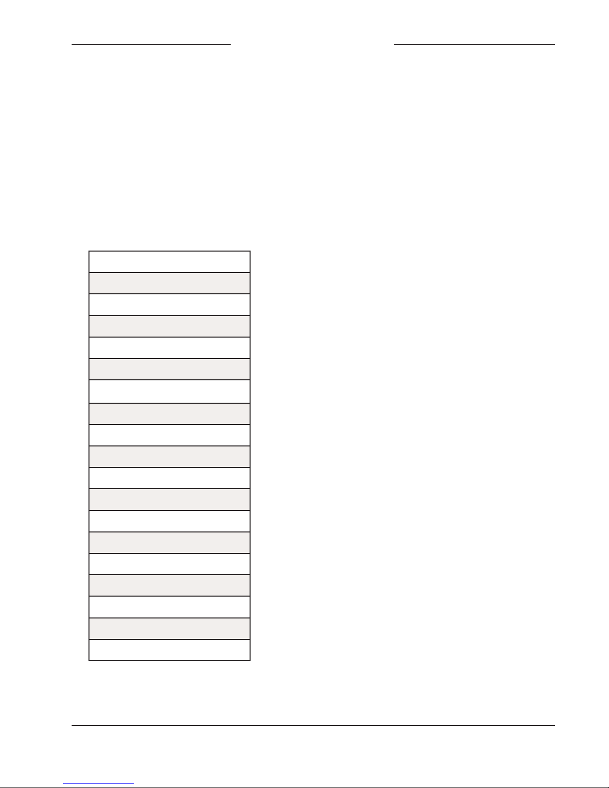
Bi-Level and Tri-Level Video: See table below
Video Format
NTSC (“Black Burst”)
PAL (“Black Burst”)
720p/50 Hz
720p/59.94 Hz
720p/60 Hz
1080psf/23.98 Hz
1080psf/24 Hz
1080i/50 Hz
1080i/59.94 Hz
1080i/60 Hz
1080p/23.98 Hz
1080p/24 Hz
1080p/25 Hz
1080p/29.97 Hz
1080p/30 Hz
1080p/50 Hz
1080p/59.94 Hz
1080p/60 Hz
Model 5401 User Guide Issue Preliminary 4, May 2018
Studio Technologies, Inc. Page 21
Page 22
Model 5401
DANTE MASTER CLOCK
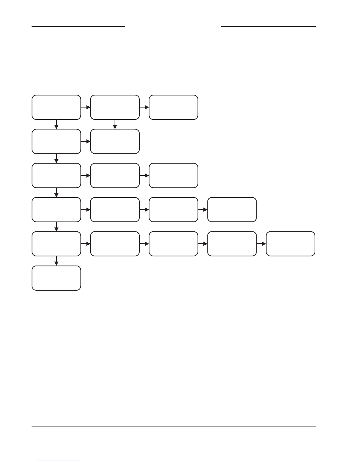
Appendix B—Model 5401 Menu
Clock Status
Cur Mgmt
IP Addr
Mgmt IP Con�g
Model 5401
Serial Number
Dante Device
Name
Reboot
Sync Status
Cur Mgmt
Subnet
Manual IP Addr
Main
Firmware Ve
r
Dante Pri
IP Addr
Sync Input
Termination
Manual Subnet
Mask
Main FPGA
Firmware Ve
r
Dante Sec
IP Addr
Sync FPGA
Firmware Ve
r
Dante
Product Ve
r
Dante
Software Ve
r
Structure
Issue Preliminary 4, May 2018 Model 5401 User Guide
Page 22 Studio Technologies, Inc.
Page 23

Model 5401
DANTE MASTER CLOCK
Appendix C—PTP v2 (IEEE-1588-2008)
Characteristics
Note: For Model 5401 PTP v2 support to be active AES67 Compatibility check box must be
enabled in Dante Controller software application.
Domain: 0
Priority 1: 114
Clock Class: 248
Accuracy: Unknown (0xFE)
Variance: 61536
Priority 2: 112
Unique ID: 00:1D:C1:XX:XX:XX
DSCP: EF (46)
Model 5401 User Guide Issue Preliminary 4, May 2018
Studio Technologies, Inc. Page 23
 Loading...