

Page 1
User Guide
Issue 1, July 2014
This User Guide is applicable for serial numbers:
M216-00151 and later
Copyright © 2014 by Studio Technologies, Inc., all rights reserved
www.studio-tech.com
50388-0714, Issue 1
Page 2

This page intentionally left blank.
Page 3

Table of Contents
Introduction ................................................................... 5
System Features ........................................................... 5
Installation ..................................................................... 10
Configuration ................................................................ 13
Dante™ Configuration ................................................... 19
Operation ...................................................................... 20
Technical Notes ............................................................. 24
Specifications ................................................................ 29
Appendix A .................................................................... 30
Appendix B .................................................................... 31
Model 216 User Guide Issue 1, July 2014
Studio Technologies, Inc. Page 3
Page 4

This page intentionally left blank.
Issue 1, July 2014 Model 216 User Guide
Page 4 Studio Technologies, Inc.
Page 5
Introduction
What This User Guide Covers
This User Guide is designed to assist you
when installing, configuring, and using
Model 216 Announcer’s Consoles. Additional background technical information
is also provided.
System Overview
The Model 216 Announcer’s Console is
designed to serve as the audio control
center for announcers, commentators, and
production personnel. This tabletop unit
supports applications utilizing the Dante™
Audio-over-Ethernet media networking
technology. The Model 216 is suitable for
numerous applications including on-air
television sports broadcasting, stadium
announce, and corporate AV. The unit integrates all on-air, talkback, and cue audio
signal routing in one compact system.
Four pushbutton switches allow the user
to control the main and talkback audio
output channels. Ease of use, configuration
flexibility, and sonic excellence are some
of the unit’s highlights.
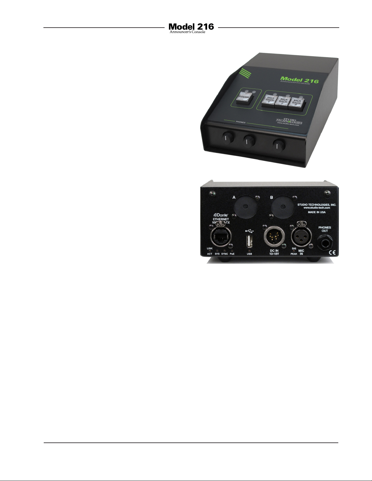
Figure 1. Model 216 front and back views
The Model 216 is compatible with the latest
broadcast and audio system environments
that use the Dante technology. An Ethernet
connection with Power-over-Ethernet (PoE)
power is all that’s required to make the unit
part of a sophisticated, networked audio
system. Connect a microphone and pair of
headphones (or a broadcast headset) and
the installation is complete. Whether it’s
the on-air audio, the talkback audio, or the
headphone cue feed, superior audio quality
is always maintained. A range of configuration choices allow the desired operating
parameters to be easily selected. And while
flexible, the user is presented with an easyto-use set of controls and indicators.
Model 216 User Guide Issue 1, July 2014
Studio Technologies, Inc. Page 5
System Features
User Controls and Status
Indicators
Four pushbutton switches, five LED indicators, and three rotary controls provide the
user with a clear, easy-to-use interface. One
pushbutton switch controls the status of
the main output. This is the audio channel
intended for on-air, announcement, or other
primary uses. Two LEDs display the on/off
status of the main output. Three additional
pushbutton switches control the status of
the talkback output channels. These are
the audio signal used to communicate with
producers, directors, spotters, or other
Page 6

behind-the-scenes production personnel.
A status LED is associated with each of
the talkback pushbuttons. The pushbutton switches use gold-plated contacts for
reliable long-term operation and include
backlighting using white LEDs. Three rotary
controls allow the user to adjust the content and level of the headphone output.
Microphone Input
The Model 216 provides a high-performance microphone preamplifier which
offers low-noise, low-distortion, and high
headroom amplification over a 19 to 64 dB
range. The gain is adjustable in 3-dB steps
using pushbutton switches accessible on
the bottom of the unit. A 2-digit display indicates the amplification in dB. The microphone input is compatible with balanced
dynamic or condenser microphones.
Phantom power is provided and meets the
worldwide P48 standard. It can be enabled
or disabled as required. A dual-color LED
indicator serves as an aid for optimizing
the setting of the preamplifier’s gain. Microphone signals are connected to the Model
216 by way of a standard 3-pin female XLR
connector.
Output Channels and their
Operation
By way of the Dante interface, the Model
216 provides a main output channel and
three talkback output channels. The main
output channel is designed to serve as the
on-air, stadium announcement, or other primary audio feed. The talkback output channels are intended to provide production
trucks, control rooms, or support personnel
with talent-originated cue signals.
A large part of the Model 216’s unique
power is the ability to configure the operation of the main and talkback functions.
To meet the needs of the many specific
broadcast and production applications, a
variety of pushbutton operating modes are
available. The main pushbutton can be selected to operate from among four modes.
In the “push-to-mute” mode the pushbutton performs a momentary mute of the
audio signal associated with the main
output channel. In this way a “cough”
pushbutton function is created, something
typically required for television sports
broadcasting. In the “push-to-talk” mode
the pushbutton provides a momentary
active function for the main output. This
mode would be appropriate for an application such as stadium announcement. An
alternate action “latching” configuration
allows the pushbutton to enable or disable
the audio signal associated with the main
output channel as desired. This is useful
in radio broadcasting, announce-booth, or
voice-over applications. The fourth mode
provides a hybrid function, supporting
both push-to-talk and tap-to-enable/tap-todisable operation. This operation is similar
to that found in many broadcast intercom
system user stations.
The three pushbutton switches associated with the talkback functions can be
configured to operate from either of two
modes. One of the modes supports a
“push-to-talk” function. This is typically
used for on-air broadcast applications.
The other mode provides a hybrid function, the operation of which is discussed in
the previous paragraph. The hybrid mode
is especially useful when the Model 216 is
used in a production-support application.
Overall Model 216 operation can be configured from among one on-air and two
production modes. The Model 216’s onair mode is appropriate for on-air television, radio, and streaming broadcast
Issue 1, July 2014 Model 216 User Guide
Page 6 Studio Technologies, Inc.
Page 7

applications. When on-air is selected the
audio signal associated with the main
output channel will always mute when one
or more of the talkback functions is active.
This prevents audio that’s intended for
production or support personnel from being sent out the on-air audio path.
For non-on-air applications, the Model 216
can be configured to operate in either of
two “production” modes. These allow the
main output to be used as a third talkback
output channel, rather than always muting
when a talkback function is active. Using these production modes the unit can
be even more powerful when used in a
live event application, such as serving as
a small “IFB” console for a sports-event
spotter, musical director, or production
assistant. In addition to changing how
the main output functions, one of the
production modes also supports using
the headphone output for connection
with amplified speakers. The headphone
output level will automatically be reduced
(attenuate or “dim”) whenever the main
or talkback output channels are active.
This can enhance intelligibility and help
prevent acoustical feedback from occurring between the speakers and the active
microphone.
Headphone Output
The Model 216 provides a number of
configuration choices that relate to the
headphone output. These choices impact
which audio sources are utilized, how the
rotary level controls function, and what
sidetone action will take place. Four headphone control configuration modes are offered. These modes impact how the three
rotary controls adjust the four Dante input
channels and the sidetone audio signals.
The first two modes support standard onair applications and use only Dante input
channels 1 and 2. In the broadcast world
these two signals are often referred to
as talent cue or IFB audio. They typically
originate in production trailers or control
rooms and provide one channel of program-with-interrupt audio and a second
channel with program-only audio. The
third and fourth configuration modes allow
all four of the Dante-provided audio sources to be utilized. These can be useful for
more complex or specialized situations.
The three headphone level controls (“rotary pots”) are provided for setting the “mix”
of the selected sources as well as adjusting the overall headphone output level.
How these controls function depends on
the selected headphone control mode.
As previously mentioned, the first mode
is intended to support traditional on-air
sports applications. In this mode the left
and center controls act in a dual-channel
(“level/level”) fashion, allowing independent control of the left- and right-channel
volume.
For use with dual-channel or stereo cue
signals, the second mode provides a stereo (“level/balance”) mode. In this mode
the left control adjusts the level of both
input channels 1 and 2, while the center
control allows adjustment of the left/right
level balance. In both modes the right
control is used to adjust the level of the
sidetone signal.
In the third headphone control mode the
left control adjusts the level of both input channels 1 and 2, the center control
adjusts the level of both input channels 3
and 4, while the right control adjusts the
sidetone level.
Model 216 User Guide Issue 1, July 2014
Studio Technologies, Inc. Page 7
Page 8

The fourth headphone mode uses the left
control to adjust the level of input channel
1, the center control to adjust the level of
input channel 2, and the right control to
adjust the level of both input channels 3
and 4. In this mode the sidetone function
is not active.
The sidetone function allows audio from
the Model 216’s microphone preamplifier
to be routed to the headphone output.
This can be useful, providing the user
with an aural confirmation of the signal
connected to the mic input. It is especially
important when a “mix-minus” talent cue
signal is provided for the user. For application flexibility the sidetone function can
be configured from among four choices,
specifying when it will be active in relation to the status of the main and talkback
functions.
To help minimize the chance of broadcast
cues being missed, the action of the level
controls can be configured so that there’s
always a minimum headphone output
level. Alternately, the controls can be configured to fully mute when they are at their
minimum (fully-counterclockwise) position.
When the level control on the right side is
used for sidetone it will always allow the
sidetone signal to be fully muted.
The headphone output was designed to
meet the needs of contemporary headphones and headsets. Specifically, the
output circuits act as voltage drivers rather
than power drivers. In this configuration
they can provide high output levels with
very low distortion and noise, along with
minimal current consumption. The output
circuits can safely drive stereo or mono
loads. This ensures that all types of headphones, headsets, and earpieces can be
directly connected.
Dante Audio-over-Ethernet
Audio data is sent to and from the Model
216 using the Dante Audio-over-Ethernet
media networking technology. For flexibility in meeting a variety of sonic requirements bit depths of up to 24 and sample
rates of 44.1 and 48 kHz are supported.
Audio output (transmit) and input (receive)
channels on associated Dante-enabled
devices can be assigned to the Model
216 using the Dante Controller software
application. This makes selecting the way
in which the Model 216 fits into an application a simple matter. For example, the
main audio output channel can be assigned to the input of an audio console.
The talkback audio output channels could
be assigned to inputs on a matrix intercom
system. No special routing or “multing”
using cables or patch points is required
to send the output channels to multiple
destinations. And a single mouse-click
is all that’s required to reroute the audio
signals.
On the input side, the Model 216 allows
up to four headphone cue sources to be
received from an audio console, matrix
intercom system, or a variety of other
Dante-enabled devices; the sources don’t
need to originate from the same device.
“Program” audio could be supplied by
an audio console while “IFB” (interrupted
foldback or talent cue) audio could be
supplied by a matrix intercom system.
Ethernet Data, PoE, and DC
Power Source
The Model 216 connects to a data network
using a standard 100 Mb/s twisted-pair
Ethernet interface. The physical interconnection is made by way of a Neutrik® etherCON RJ45 connector. While
Issue 1, July 2014 Model 216 User Guide
Page 8 Studio Technologies, Inc.
Page 9

compatible with standard RJ45 plugs,
etherCON allows a ruggedized and locking interconnection for harsh or high-reliability environments. The Model 216’s
operating power can be provided by way
of the Ethernet interface using the Powerover-Ethernet (PoE) standard. This allows
fast and efficient interconnection with the
associated data network. To support PoE
power management, the Model 216’s PoE
interface reports to the power sourcing
equipment (PSE) that it’s a class 2 (low
power) device. The unit can also be powered using an external source of 12 volts
DC. For redundancy, both power sources
can be connected simultaneously. If both
sources are connected PoE will power the
unit. Four LEDs display the status of the
network connection, PoE power source,
and Dante interface.
Configuration and Flexibility
Model 216 configurations are made using
twelve DIP switches and two pushbutton
switches. The 12-position switch array
configures parameters such as the pushbutton operating modes, sidetone function, headphone control assignment, and
the system mode. The pushbuttons are
used to set the gain of the microphone
preamplifier and control the on/off status
of the microphone phantom power function. The switches and pushbuttons are
accessible via the bottom of the Model
216’s enclosure; the unit does not have to
be disassembled. Changes made to any
of the configuration parameters become
active immediately. To prevent unwanted
access to the configuration switches and
pushbuttons a security panel, included
with each unit, is attached to the bottom
of the enclosure.
In the world of broadcast and production
audio it’s fair to say that applications vary
widely. To this end, one or two additional
XLR connectors can easily be mounted
into the Model 216’s back panel. Multiple
3-position “headers” located on the Model
216’s circuit board provide technician
access to many of the input and output
connections. Using a variety of optional
factory-supplied modules and interface
cable kits allows a Model 216 to be optimized to meet the needs of specific applications. For example, some applications
may prefer to use a multi-pin XLR connector to interface with a headset. This can
easily be accomplished by installing the
appropriate 6- or 7-pin XLR connector kit
and making a few simple connections.
Other applications may benefit from having “mult” or “loop-through” connections,
something easily incorporated into a Model
216. And access to the relay contacts can
be made adding a 4-pin XLR connector kit.
Two general-purpose relay contacts are
provided on the Model 216’s circuit board.
Accessible using 3-pin “header” connectors they allow specialized configurations
to be created. Under software control, the
form-A (normally open) solid-state relay
contacts follow the state of the main and
talkback 1 pushbuttons. Taking advantage
of the two locations provided for additional
XLR connectors, a technician may easily
implement a variety of functions such as
a tally indication or audio muting during
talkback.
Future Capabilities &
Firmware Updating
The Model 216 was designed so that its
capabilities can be enhanced in the future.
The primary additions will be in the area of
Dante remote control functionality. Once an
Model 216 User Guide Issue 1, July 2014
Studio Technologies, Inc. Page 9
Page 10
industry-standard has been established
it’s expected that remote control of microphone preamplifier gain and microphone
phantom power on/off will be available.
Output channel status will also be able
to be reported as well as responding to
status (tally) indications that are received.
These features will allow integration with
devices such as audio consoles, signals
processor units, and matrix intercom
systems.
A USB connector, located on the Model
216’s back panel, allows the operating
firmware (embedded software) to be updated using a standard USB flash drive.
The Model 216 uses Audinate’s Ultimo™
integrated circuit for implementing Dante.
The integrated circuit’s firmware can be
updated via the Ethernet connection, helping ensure that its capabilities remain up
to date.
Dante-Enabled Announcer
Console Products
The Model 216 is just one in a series of
Dante-enabled announcer console products available from Studio Technologies.
For applications that require an alternate
set of features the other products in the
200-Series should be reviewed. Complete
information is available on the Studio
Technologies website.
Installation
In this section signal interconnections
will be made using the connectors located
on the back panel of the Model 216. A
microphone signal will be interfaced by
way of a 3-pin XLR connector. A ¼-inch
3-conductor phone jack is provided for
the headphone output. An Ethernet data
connection will be made using either a
standard RJ45 patch cable or an etherCON protected RJ45 plug. A 4-pin XLR
connector allows the connection of an
external source of 12 volts DC.
System Components
Included in the shipping carton are the following: Model 216 Announcer’s Console,
user guide, and pushbutton label sheet.
Microphone Input
The Model 216 is compatible with balanced dynamic and condenser microphones. Depending on the application,
the microphone may be part of a headset
or be an independent handheld or standmounted model. The Model 216’s P48
power source will support essentially all
phantom-powered microphones. The
quality of the Model 216’s microphone
preamplifier and associated circuitry is
such that special applications may benefit from using “high-end” microphones.
If selected appropriately models from
manufacturers such as AKG, Beyer, DPA,
Sennheiser, and Shure will perform very
well in Model 216 applications.
Microphone interconnection is made
by way of a 3-pin female XLR connector which is located on the Model 216’s
back panel. The mating connector (male)
should be wired so that pin 2 is signal
high (+ or hot), pin 3 is signal low (– or
cold), and pin 1 is shield. It’s possible that
an unbalanced microphone will also work
correctly. In this case, the mating connector (male) should be wired so that pin 2
is signal high (+ or hot), and signal common/shield is connected to both pins 1
and 3.
Issue 1, July 2014 Model 216 User Guide
Page 10 Studio Technologies, Inc.
Page 11

As of the writing date of this guide, the
Sennheiser HMD 26 headset is very popular for on-air sports broadcasting use. A
fine product, it works very well with the
Model 216. Adding the suffix “-XQ” to the
headset’s full part number (HMD 26-600XQ) specifies a 3-pin male XLR connector
for the dynamic microphone and a ¼-inch
3-conductor plug for the stereo headphones. This configuration is very useful,
allowing the headset to work directly “out
of the box” with the Model 216. Another
headset that users have reported being
satisfied with is the audio-technica BPHS1.
Offered at a lower price-point, it may be
applicable for some applications.
If the writer may digress for a moment to
recount a story… an audio dealer once
shared a secret with me concerning
headsets. He loved selling the “lowerend” (much less expensive) models of
name-brand headsets, which he did by
the veritable “boatload.” Why? Because
these usually broke soon after going into
service! He knew that on a regular basis
he’d receive orders for more of them. Had
these users, from the beginning, purchased only premium-quality headsets,
their total cost of ownership would have
been much less. Enough said…
Headphone Output
The Model 216’s headphone output is
compatible with stereo or mono headphones, headsets, or earpieces. Connecting devices with a nominal impedance
of 100 ohms or greater is preferred. This
shouldn’t prove to be an issue since essentially all of the contemporary devices
meet this recommendation.
Devices are connected to the headphone
output by way of a ¼-inch 3-conductor
phone jack located on the Model 216’s
back panel. As is standard for stereo
headphones, the left channel is connected
to the tip lead of the ¼-inch headphone
jack. The right channel is connected to
the ring lead of the jack. Common for both
channels is connected to the sleeve lead.
Devices with ¼-inch 2-conductor “monaural” plugs can also be used with the Model
216’s headphone output. In this arrangement only the tip lead (left channel) will be
active. The 2-conductor plug will physically connect (“short”) the ring lead (right
channel) to the sleeve lead (common).
Technically this won’t damage the circuitry
associated with the right-channel headphone output since 100 ohm protection
resistors are electrically in series with the
headphone output circuits.
Ethernet Connection
An Ethernet connection that supports
100BASE-TX is required for the Model
216’s Dante Audio-over-Ethernet connectivity. A 10BASE-T connection is not
sufficient for Model 216 operation. A
1000BASE-T (“GigE”) connection is not
supported unless it can automatically
“fall back” to 100BASE-TX operation. An
Ethernet connection that supports Powerover-Ethernet (PoE) is preferred as it will
provide operating power for the Model
216. For Ethernet with PoE switch (PSE)
power management the Model 216 will
enumerate itself as a PoE class 2 device.
If PoE is not available an external 12 volt
DC power source can also be connected.
This will be discussed in the next section
of this guide.
The 100 Mb/s twisted-pair Ethernet connection is made by way of a Neutrik etherCON protected RJ45 connector that is
located on the back panel of the Model
216. This allows connection by way of a
Model 216 User Guide Issue 1, July 2014
Studio Technologies, Inc. Page 11
Page 12

cable-mounted etherCON plug or a standard RJ45 plug. The Model 216’s Ethernet
interface supports auto MDI/MDI-X so
that most cabling implementations will
be correctly supported.
External 12 Volt DC Input
An external source of 12 volts DC can
be connected to the Model 216 by way
of the 4-pin male XLR connector which
is located on the back panel. While the
requirement for the external source is
nominally 12 volts, correct operation will
take place over a 10 to 18 volt range. The
Model 216 requires 270 milliamperes at
12 volts DC for correct operation. The DC
source should be terminated to a 4-pin
female XLR connector with pin 1 negative
(–) and pin 4 positive (+).
As previously discussed in this guide,
an Ethernet connection that provides
Power-over-Ethernet (PoE) can serve as
the Model 216’s power source. Alternately,
an external 12 volt DC source can be connected. For redundancy, both PoE and the
external source can be connected at the
same time. If both PoE and an external
12 volt DC source are connected, power
will be drawn only from the PoE supply.
If the PoE source becomes inoperative
the 12 volt DC source will provide the
Model 216’s power with no interruption
in operation.
text printed on clear material, are placed
under the clear caps on the top of the
pushbuttons.
From the factory the left pushbutton is
labeled COUGH, the middle pushbutton is
labeled TALKBACK 1, and the right pushbutton is labeled TALKBACK 2. These were
selected to be appropriate for many on-air
applications in English-speaking locations.
But it’s expected that these may need to
be changed to meet the needs of specific
applications.
As a “head start” for some applications,
a clear sheet with a number of commonly
used pushbutton designations printed on
it is included in the shipping carton. These
were created at the factory using a standard personal computer graphics program
and laser printed onto sheets of transparency film. The desired pushbutton labels
can be cut out with a pair of scissors or an
X-ACTO® knife following the printed guide
lines that indicate the required size.
The clear lens on top of each pushbutton
cap can be removed with a fingernail or
small screwdriver. Be certain not to scratch
the pushbutton if a screwdriver or other
small tool is used. The clear label can be
removed and replaced. The cap is then
snapped back into the top of the housing
using finger-pressure only. No tool is required to replace the cap.
Pushbutton Labeling
The four pushbutton switches used in the
Model 216 were selected for several reasons. Foremost was the fact that they are
highly reliable, using gold-plated contacts
for long life in less-than-ideal environments. A second reason was that applying
customized labels to the pushbutton
caps would be very simple. The labels,
Issue 1, July 2014 Model 216 User Guide
Page 12 Studio Technologies, Inc.
If you need to make your own labels the
process is quite simple. Use a personal
computer to create the desired text. The
finished label size should be 0.625-inches
(15.8 mm) square. The completed artwork
can then be printed on transparency film
sheets using a laser or inkjet printer. These
sheets are readily available from most office supply stores. A pair of scissors or an
X-ACTO (razor) knife will complete the task.
Page 13

Configuration
For the Model 216 to support the needs
of specific applications a number of operating parameters must be configured.
These include microphone preamplifier
gain, phantom power on/off, pushbutton
operation, headphone control assignment,
and operating modes. Two pushbutton
switches and a 12-position DIP switch assembly are used to establish the desired
configuration. A 2-digit LED display will
indicate the gain of the microphone preamplifier and the phantom power on/off status. The pushbutton switches, LED display,
and DIP switches are accessed through
an opening in the bottom of the Model
216’s enclosure. The enclosure does not
have to be disassembled to gain access.
To prevent unauthorized personnel from
changing the configuration settings, a
security panel is attached to the bottom
of the Model 216’s enclosure. For convenience, the security panel provides a summary of the configurable parameters and
related information. Refer to Appendix A for
a representative view. The security panel
is held in place by means of four rubber
bumpers (“feet”) that have built-in screws.
Using your fingers, remove the four bumpers so that the panel can be removed.
Refer to Figure 2 for a detailed view of the
configuration switch assemblies.
Microphone Preamplifier Gain
and Phantom Power
Two pushbutton switches, located on the
bottom of the Model 216, are used to set
the gain of the microphone preamplifier
and select the on/off status of the phantom
power source. A 2-digit LED display provides a status indication of both functions.
Figure 2. Bottom view of Model 216 showing
configuration switches and 2-digit display
LED Display Time-Out
As previously mentioned, a 2-digit LED
display provides an indication of the gain
of the microphone preamplifier as well as
the on/off status of the phantom power
supply
display will automatically stop lighting
approximately 100 seconds after the last
time that either of the bottom pushbutton
switches is pressed. A different time-out
interval applies after the Model 216 has
had
is pressed; the display will light for approximately 10 seconds and then turn off.
In most cases this display auto-off function
will lead a technician or installer to initially
. As a power-saving measure the
power applied and neither pushbutton
Model 216 User Guide Issue 1, July 2014
Studio Technologies, Inc. Page 13
Page 14

observe that the 2-digit display is not lighting. For example, a Model 216 has been
operating normally but the security panel
has just been removed. To cause the
2-digit display to again light just requires
pressing either of the bottom pushbutton switches. This “wakes up” the display
and resets the timer. The initial press of
either pushbutton will not cause the gain
to change or impact the phantom power
on/off status. Only when the 2-digit display
is active will the pushbuttons impact the
settings.
Microphone Preamplifier Gain
The two pushbutton switches are used
to select the gain of the microphone
preamplifier. The range is 19 to 64 dB in
3 dB steps. There’s no problem changing
the gain setting while the unit is operating.
Small audio clicks or pops might occur
during gain transitions, but this shouldn’t
be a major issue as long as associated
monitor loudspeakers are temporarily
attenuated or muted. As expected, the
2-digit LED display will directly indicate,
in dB, the selected amount of gain.
Selecting the correct amount of gain for an
application might take a little experimentation. The goal is to bring the mic’s signal
up to the Dante reference level which is
typically considered to be –20 dBFS. (This
is 20 dB below digital maximum.) Operating at this signal level will help ensure the
delivery of “clean” audio to the destination
device or devices.
There’s no “perfect” gain setting that this
guide can recommend. The two issues
that impact the setting are output sensitivity of the connected microphone and
the acoustical output level of the microphone’s user. With some headset microphones, such as the Sennheiser HMD26,
selecting an initial setting of 43 or 46 dB
would be appropriate. Users who speak
loudly might need to have the gain reduced
to 40 or even 37 dB. Quiet users might
need 49 or 52 dB of gain.
Using the device that’s digitally connected
(via Dante) to the Model 216’s main output
channel is typically the best way to check
the signal level and the setting of the mic
preamplifier. Most devices have some
method of providing an indication of the
digital level, either in the form of a numerical value, virtual meter, or LED-based meter
display. The Studio Technologies’ Model
5202 Dante to Phones and Line Output
Interface would also be an excellent means
of monitoring the Model 216’s output level.
The Model 5202 provides a 2-channel LED
level that is calibrated in dBFS.
A dual-color LED, located on the back
panel directly below the microphone input connector, is provided as an aid when
using the Model 216. It can also be useful
when setting the gain of the Model 216’s
microphone preamplifier. It provides a
3-step indication of the output level of
the microphone preamplifier. It will light
green when the signal level is –40 dBFS or
greater, a mix of green and red when the
signal level is –14 dBFS or greater, and red
only when the signal level is –4 dBFS or
greater. When the gain of the microphone
preamplifier is set optimally a normal signal
applied to the microphone input will cause
the LED to light green with an occasional
“peak” signal causing the LED to light both
green and red at the same time. A more
conservative gain setting would find that
the LED would only light green. A gain
setting that results in the LED ever lighting
only red is incorrect. The gain must be reduced or the audio quality will be severely
compromised.
Issue 1, July 2014 Model 216 User Guide
Page 14 Studio Technologies, Inc.
Page 15

Phantom Power On/Off
The Model 216 can provide P48 (48 volt
DC nominal) phantom power to the connected microphone. The two pushbutton
switches control whether or not phantom
power is active. Pressing both pushbuttons simultaneously will toggle (change)
the on/off state. The decimal point indicator, located on the lower right corner of
the 2-digit LED display, is used to show
the phantom power on/off status. When
the decimal point is lit phantom power is
enabled. By the very nature of phantom
power it should be able to be left enabled
at all times. But generally people prefer
to turn it off unless required for a specific
microphone.
Operating Modes
Twelve DIP switches are used to configure
the Model 216’s operating modes. Technically, these switches “talk” to a microcontroller integrated circuit and associated software that give the Model 216 its
“smarts.” The software has been carefully
designed to provide a number of different
ways in which the unit can function. It’s
important to carefully review the available
options and choose the ones that best
meet the needs of a specific application.
Note that the switches can be changed
even while the Model 216 is powered up
and operating. The unit’s operating characteristics will change in “real-time” in
response to switch changes.
Main Button Mode
Switches 1 and 2 configure how the main
pushbutton functions.
Figure 3. Main button mode switch settings
There are four available modes:
• Push to Mute: In this mode the audio
signal on the main output channel
is normally active. The audio signal
will mute whenever the pushbutton is
pressed and held. This is the “cough”
mode typically used for on-air sports
broadcasting applications.
• Push to Talk: In this mode the audio
signal on the main output channel is
normally muted. The main audio signal
will become active whenever the pushbutton is pressed and held.
• Latching: In this mode the audio signal
on the main output channel will change
between its active and muted states
whenever the pushbutton is pressed.
Upon power up the audio signal on the
main output will be in its muted state.
• Hybrid: This mode is a combination
of push to talk and latching action. It’s
similar to the way talk pushbuttons
function on user stations associated
with broadcast and production intercom
systems. If the pushbutton is pressed
and held, the audio signal on the main
Model 216 User Guide Issue 1, July 2014
Studio Technologies, Inc. Page 15
Page 16

output channel will become active until
the pushbutton is released. If the pushbutton is momentarily “tapped” the
audio signal on the main output channel
will change state. Upon power up the
audio signal on the main output channel
will be in its muted state.
Talkback Button Mode
Switch 3 configures the way the talkback
pushbuttons function.
Figure 4. Talkback buttons switch settings
Figure 5. Button backlight intensity switch
settings
Two choices are available: low and high.
Low is appropriate when the Model 216
is to be used in an environment where the
ambient light level is low. High would be
appropriate where other light sources
in the physical area may make the pushbuttons more difficult to identify. High may
also be useful when identification markings have been inserted under the clear
lens caps.
Two modes are available:
• Push to Talk: In this mode the audio
signal on the talkback output channels
is normally muted. An audio signal will
become active whenever its associated
pushbutton is pressed and held.
• Hybrid: This mode is a combination
of push to talk and latching action. If
a pushbutton is pressed and held the
audio signal associated with that talkback output channel will become active
until the pushbutton is released. If a
pushbutton is momentarily “tapped” the
audio signal on the associated talkback output channel will change state.
Upon power up the audio signals on the
talkback output channels will be in their
muted state.
Button Backlight Intensity
Switch 4 selects the intensity of the white
LEDs that provide backlighting for the four
pushbutton switches.
Sidetone
Switches 5 and 6 configure the way the
sidetone function operates.
Figure 6. Sidetone switch settings
Four modes are available:
• Off: In this mode the sidetone function
not active.
• Main Button: In this mode the sidetone
function will be active whenever the
audio signal is present on the main
output channel.
Issue 1, July 2014 Model 216 User Guide
Page 16 Studio Technologies, Inc.
Page 17

• Talkback Button: In this mode the sidetone function will be active whenever the
audio signal is present on either or both
of the talkback output channels.
• Main and Talkback Buttons: In this mode
the sidetone function will be active whenever the audio signal is present on the
main and/or talkback output channels.
Headphone Control Assignment
Switches 7 and 8 are used to select the
functioning of the three rotary level controls.
Figure 7. Headphone control assignment switch
settings
There are four choices available:
• Audio input channel 1 is assigned to the
left headphone output channel and its level is controlled by the rotary level control
on the left side of the front panel. Audio
input channel 2 is assigned to the right
headphone output channel and its level
is controlled by the rotary level control
located in the center of the front panel.
Sidetone audio is assigned to both the
left and right headphone output channels
and its level is controlled by the rotary
level control on the right side of the front
panel. Audio inputs 3 and 4 are not used.
• Audio input channel 1 is assigned to
the left headphone output channel and
audio input channel 2 is assigned to the
right headphone output channel. The
overall level of audio inputs 1 and 2 are
controlled by the rotary level control located on the left side of the front panel.
The balance (relative level) of both these
signals is controlled by the rotary level
control located in the center of the front
panel. Sidetone audio is assigned to
both the left and right headphone output
channels and its level is controlled by
the rotary level control on the right side
of the front panel. Audio inputs 3 and 4
are not used.
• Audio input channel 1 is assigned to
the left headphone output channel and
audio input channel 2 is assigned to
the right headphone output channel.
The overall level of audio inputs 1 and 2
are controlled by the rotary level control located on the left side of the front
panel. Audio input channel 3 is assigned
to the left headphone output channel
and audio input channel 4 is assigned
to the right headphone output channel.
The overall level of audio inputs 3 and 4
are controlled by the rotary level control
located in the center of the front panel.
Sidetone audio is assigned to both the
left and right headphone output channels and its level is controlled by the
rotary level control on the right side of
the front panel.
• Audio input channel 1 is assigned to
the left headphone output channel and
its level is controlled by the rotary level
control on the left side of the front panel.
Audio input channel 2 is assigned to the
right headphone output channel and
its level is controlled by the rotary level
control located in the center of the front
Model 216 User Guide Issue 1, July 2014
Studio Technologies, Inc. Page 17
Page 18

panel. Audio input channel 3 is assigned
to the left headphone output channel
and audio input channel 4 is assigned
to the right headphone output channel.
The overall level of audio inputs 3 and 4
is controlled by the rotary level control located on the right side of the front panel.
The sidetone function will not be active.
When the rotary level control on the right
side of the front panel has been assigned
to control the sidetone level the setting of
the headphone minimum level mode will
not impact it. In this case when the control
is in its fully counterclockwise position it
will always cause the sidetone level to be
fully muted.
Headphone Minimum Level
Switch 9 is used to configure the headphone output’s minimum level. In the
–40 dB setting the minimum headphone
output level is approximately 40 dB below
maximum. The headphone output will never fully mute. This ensures that any audio
signal present on the assigned audio input
channels (1 and 2 or 1, 2, 3, and 4) will
always be present on the headphone output. In most on-air broadcast applications
this is the appropriate setting, ensuring
the some level of signal is always present.
Figure 8. Headphone minimum level switch
settings
Operating Modes
Switches 11 and 12 are used to configure
the overall operating mode of the Model
216. Specifically, they determine how the
main output channel operates vis-à-vis the
talkback output channels as well as one
facet of the headphone output’s function.
Understanding how these three modes
impact overall system operation will ensure that correct operation and maximum
usability will occur.
When full mute is selected moving any level
control to its fully counterclockwise position
will cause its associated channel to fully
mute. If a rotary level control is set to serve
as a balance control, moving it to either fully
counterclockwise or fully clockwise position will cause the associated signal to fully
mute. Selecting the full mute mode may be
appropriate for applications where minimizing the chance of audio “leakage” is important. This could occur when the connected
headset or headphones are at times placed
Figure 9. System mode settings
• When selected to the on-air mode, the
audio signal on the main output channel will mute whenever the audio signal
on either or both of the talkback output
channels is active. The on-air mode
should be selected for all on-air broadcast applications when it’s imperative
that the audio signal on the main output
channel be muted whenever on-air talent
uses a talkback output channel to communicate with production personnel.
on a desk or tabletop.
Issue 1, July 2014 Model 216 User Guide
Page 18 Studio Technologies, Inc.
Page 19

• When the system mode is set for pro
duction with dim, the audio signal on the
main output channel is never muted in
response to the audio signal on either
or both of the talkback output channels
being active. In addition, the level of the
headphone output is dimmed (reduced
in level or attenuated) by 18 dB whenever the main or talkback output channels
have audio present. In this way the four
output channels can be used independently, with neither impacting the other.
And, the headphone output can be connected to amplified loudspeakers. The
speakers will reduce in level whenever
one of the output channels is active,
preventing acoustical feedback.
• When the system mode is set for production, the audio signal on the main
output channel is never muted in response to the audio signal on either or
both of the talkback output channels
being active. This mode allows the main
output channel to be used, for example,
as an additional talkback output. In
this way the main and talkback output
channels can be used independently,
with neither impacting the other. This
also allows all four pushbuttons to be
used simultaneously. When selected for
the correct application, the production
mode can prove to be very useful. But
it’s not appropriate for on-air use!
-
Conclusion
Once the mic preamp gain, phantom
power, and operating mode have been set
to the desired configuration, the security
panel can be reattached. The four rubber
bumpers should be hand-tightened only.
No tools should be used.
Dante
Configuration
A number of the Model 216’s Dante-related
parameters can be configured. These configuration settings will be stored in nonvolatile memory within the Model 216’s
circuitry. The Model 216 uses the Ultimo
4-input/4-output integrated circuit to implement the Dante architecture. This dictates
which parameters can be configured and
what choices are available.
The audio input (receive) and output (transmit) channels associated with the Model
216’s Dante interface must be assigned to
desired sources and destinations. This will
typically be done with the Dante Controller software application which is available
for download free of charge at www.audinate.com. Versions are available to support
Windows® and OS X® operating systems.
Within Dante Controller a “subscription” is
the term used for routing a transmit flow
(a group of output channels) to a receive
flow (a group of input channels). Note that
as of the writing of this guide the Ultimo
integrated circuit limits the number of Dante
flows to two in each direction (two transmit
and two receive).
The Model 216 has a default Dante device
name of ST-M216 and a unique suffix. The
suffix identifies the specific Model 216 that
is being configured. The Model 216 provides
four Dante transmitter (output) channels
with the default names of Main, Talkback 1,
Talkback 2, and Talkback 3. The Model 216
has four Dante Receiver (input) channels
with default names of Headphone Ch1,
Headphone Ch2, Headphone Ch3, and
Headphone Ch4. Using Dante Controller
these names can be revised as appropriate
for the specific application.
Model 216 User Guide Issue 1, July 2014
Studio Technologies, Inc. Page 19
Page 20

The Model 216 will support audio sample
rates of 44.1 kHz or 48 kHz with the ability
to select pull-up/pull-down values. These
parameters can be selected using the
Dante Controller application but in most
applications 48 kHz will be appropriate.
The Model 216 can serve as the clock
master for a Dante network but in most
cases that would not be optimal.
Operation
At this point the audio, Ethernet, and power connections should have been made.
The pushbutton labels may have been
revised. The desired configuration should
have be made using the pushbutton and
DIP switches. The Dante input (receiver)
and output (transmitter) channels should
have been routed using the Dante Controller software application. Normal operation
of the Model 216 can now begin.
Initial Operation
The Model 216 will begin functioning a
few seconds after its power source is
connected. As previously discussed, the
power source can be provided by Powerover-Ethernet (PoE) or an external source
of 12 volts DC. If both are connected the
PoE source will power the unit. Should
PoE subsequently no longer be available
uninterrupted operation will continue using
the external source.
Upon Model 216 power up most of the
status and backlight LEDs along with the
2-digit display will activate in a test sequence. The PoE, USB, and SIG/PEAK
LEDs, located on the back panel, will light
one after another. On the top surface of
the Model 216 the two status LEDs and
the backlight LED associated with the
main pushbutton switch and the status
LED and the backlight LEDs associated
with the talkback pushbutton switches will
momentarily light in sequence. Once that
sequence has completed all the LEDs will
begin to function normally.
The 2-digit LED display is visible on the
bottom of the unit when the security panel
is removed. Upon unit power up, all segments of each display digit will light briefly
as a confirmation that they are functioning.
Then the version number of the operating firmware (embedded software) will
briefly display. For example, the fi
ware version shipped with the Model 216
would display 1.0. Then the gain of the
microphone preamplifier (in dB) and the
phantom power on/off status will display
and remain active. Unless either or both
the gain/phantom pushbutton switches are
pressed, approximately 10 seconds after
the unit begins operation the display will
stop lighting. This is a power saving measure. The display will again light after either
or both of the pushbuttons are pressed.
Note that the way in which the LINK/ACT,
SYS, and SYNC LEDs (all located below
the Ethernet connector) will light depends
on characteristics related to the connected
Ethernet signal and the configuration of the
unit’s Dante interface. This will be covered
in detail in the next section of this guide.
After the power-up sequence has completed the Model 216 will begin normal
operation. Depending on the selected
configuration, one status LED associated
with the main pushbutton switch may be lit.
The user is now presented with four pushbutton switches, five LEDs, and three rotary
controls. These are simple to operate and
understand, as will be described in later
paragraphs.
rst firm-
Issue 1, July 2014 Model 216 User Guide
Page 20 Studio Technologies, Inc.
Page 21

Ethernet, PoE, and Dante
Status LEDs
Four status LEDs are located below the
Ethernet connector on the Model 216’s
back panel. The LINK/ACT LED will light
green whenever an active connection to
a 100 Mb/s Ethernet network has been
established. It will flash on and off in
response to data packet activity. The PoE
LED will light green whenever P
over-Ethernet (PoE) associated with the
connected Ethernet signal is providing operating power for the Model 216. The SYS
and SYNC LEDs display the operating status of the Dante interface and associated
network. The SYS LED will light red upon
Model 216 power up to indicate that the
Dante interface is not ready. After a short
interval it will light green to indicate that it
is ready to pass data with another Dante
device. The SYNC LED will light red when
the Model 216 is not synchronized with
a Dante network. It will light solid green
when the Model 216 is synchronized with
a Dante network and an external clock
source (timing reference) is being received. It will slowly light on and off green
when the Model 216 is part of a Dante
network and is serving as a clock master.
ower-
How to Identify a Specific
Model 216
The Dante Controller software application
offers an identify command that can be
used to help locate a specific Model 216.
When identify is selected for a specific
unit the SYS and SYNC LEDs on that unit
will together light slowly on and off
makes it a very simple task to observe the
selected Model 216 unit.
. This
Signal Present/Peak LED
A dual-color LED is located on the Model
216’s back panel, directly below the microphone input connector. It monitors the
output of the microphone preamplifier,
providing a 3-step signal level indication.
The LED will light green when the signal
level is –40 dBFS or greater, both green
and red at the same time when the signal
level is –14 dBFS or greater, and red when
the signal level is –4 dBFS or greater. During normal operation the LED should light
green and, with peak signals, occasionally both green and red at the same time.
If the LED is lit constantly green and red at
the same time the gain of the microphone
preamplifier most likely should be reduced.
The LED should never light red only as this
would indicate a signal that’s in danger of
reaching 0 dBFS (digital “clipping”). This
would indicate that the gain of the microphone preamplifier should be significantly
reduced.
Pushbutton Switches and
Status LEDs
Four pushbutton switches are used to
control the audio signals on the main and
talkback output channels. The way each
operates depends on the selected configuration. Five LED indicators are located
adjacent to the pushbuttons and reflect
the status of the audio signals associated
with the main and talkback output channels. The pushbuttons’ clear lenses are
backlit using white LEDs. The intensity
(brightness) of the LEDs is configured from
a choice of two values, low or high. The
backlighting does not provide an indication
of the associated pushbutton’s status nor
do they serve as a tally function, but rather
allow the pushbutton’s labeling and loca
tion to be visible in low-light conditions.
-
Model 216 User Guide Issue 1, July 2014
Studio Technologies, Inc. Page 21
Page 22

Main Button and LED
Indicators
The pushbutton on the left, factory labeled
as COUGH, functions according to the
selected configuration. Two LED indicators,
located directly above the pushbutton, are
associated with the status of the audio signal on the main output channel. The green
LED, located on the right, is lit whenever
the microphone audio signal is connected
to the main output channel. This could be
considered as an “on-air” or “mic-active”
indicator. If the Model 216’s system mode
is configured to on-air, the red LED
on the left, will be lit when the audio signal
associated with main output channel is
muted.
If the Model 216 is configured to operate
in either of the production modes, the red
LED will never light. This is to reflect the fact
that the main pushbutton has now taken
on a function similar to that of the talkback
pushbutton. To clarify, when the Model 216
is set to either of the production modes, the
red LED will never light; the green LED will
light whenever microphone audio is connected to the main output channel.
, located
Main Button Modes
Depending on the selected configuration,
there are four ways the main pushbutton
can function:
• Push to Mute: If this mode is selected
the audio signal associated with the
main output channel is normally active.
The audio signal will mute whenever the
pushbutton is pressed and held.
Push to T
•
audio signal associated with the main
output channel is normally muted. The
audio signal will become active whenever
the pushbutton is pressed and held.
alk: If this mode is selected the
• Alternate Action: If this mode is selected
the audio signal associated with the main
output channel will alternate between its
active and muted states whenever the
pushbutton is pressed. Upon power up
the audio signal will be in its muted state.
• Hybrid: This mode is a combination of
push to talk and alternate action. It’s similar to the way talk pushbuttons function
on user stations associated with broadcast or production intercom systems. If the
pushbutton is pressed and held the audio
signal associated with the main output
channel will become active until the pushbutton is released. If the pushbutton is
momentarily “tapped” the audio signal will
change state. Upon Model 216 power up
the audio signal will be in its muted state.
Main Output vis-à-vis Talkback
Activity
This short section applies only in the case
where the Model 216’s system mode is configured for on-air and the main pushbutton
mode is set to alternate action or hybrid.
Talkback activity will always cause the audio
signal associated with the main output channel to be placed in its muted state. If the
audio signal was in the “latched-on” state
when talkback activity began, once talkback
activity ends that state will resume; the audio
signal associated with the main output channel will again be in its on (“latched”) state.
Talkback Buttons and LED
Indicators
The pushbutton in the middle, factory labeled TALKBACK 1, controls the audio
signal associated with the talkback output
channel 1. The pushbutton on the right, factory labeled TALKBACK 2, controls the audio
signal associated with the talkback output
Issue 1, July 2014 Model 216 User Guide
Page 22 Studio Technologies, Inc.
Page 23

channel 2. The manner in which the talkback pushbuttons function depends on
the way they were configured. One LED
indicator, green in color, is located directly
above each talkback pushbutton. It lights
whenever the microphone audio signal
is connected to its associated talkback
output channel. If the Model 216’s system
mode is selected for on-air, whenever
either or both talkback functions is active the audio signal associated with the
main output channel will be placed in its
muted state. If the Model 216 is selected
for the production mode, the status of the
talkback pushbuttons will not impact the
status of the audio signal associated with
the main output channel.
Talkback Button Modes
Depending on the selected configuration,
there are two ways the talkback pushbuttons can function:
• Push to Talk: If this mode is selected
the audio signal associated with the
talkback output channels is normally
muted. The audio signal will become
active whenever its associated talkback
pushbutton is pressed and held.
• Hybrid: This mode is a combination of
push to talk and alternate action. If a
pushbutton is pressed and held, the
audio signal associated with that talkback output channel will become active
until the talkback pushbutton is released. If the talkback pushbutton is
momentarily “tapped” the audio signal will change state. Upon Model 216
power up the audio signal will always
be in its muted state.
Headphone Output Level
Controls
Three rotary controls (“pots”) are located on
the Model 216’s front panel and are associated with the headphone output. The way the
controls function depends on the selected
configuration. One configuration parameter
sets what audio input signals are assigned
to the controls. There are four modes available. Another parameter selects whether the
headphone output channels will maintain a
minimum output level or can be fully muted.
T
o understand exactly how the level controls
on a specific Model 216 will function requires
knowledge of how that unit has been configured. Please refer to the Configuration section of this guide for details. It may require
a bit of study to fully understand how the
controls will function. The author would like
to be able to provide a simple explanation.
But there are really four simple explanations,
one for each configuration choice!
Each level control has a mechanical step
(detent) that is located at the halfway (50%)
position of its rotation range. This is intended
to serve as an aid to Model 216 users. In
an ideal installation, setting the controls to
their detent position will result in a comfortable headphone output level. The user, in
response to a changing operating environment, can then move the level controls to
get more or less level as desired. The detent
position will always remain as a useful reference point. To achieve this condition the
audio level on the appropriate audio inputs
will have to be calibrated as required. This
is somewhat counter intuitive to the usual
mentality of just providing the user with
whatever level comes up by default. Spending a few extra minutes “trimming” the input
audio channel levels can result in much
happier, and more productive, users.
Model 216 User Guide Issue 1, July 2014
Studio Technologies, Inc. Page 23
Page 24

One of the headphone modes uses the
control in the center of the unit as a balance function. In this case the detent
position will send approximately equal
levels to both the left and right headphone
output channels. This is as one would
expect from a “stereo” balance control
such as provided in consumer electronic
equipment.
When the headphone minimum level configuration is set to –40 dB, turning a level
control to its fully counterclockwise position will cause the level of its associated
headphone output channel(s) to 40 dB
below maximum. This ensures that users
will never be fully “isolated” from potentially important cue signals. In addition,
when a control is set to provide a balance
function, turning it to either its fully clockwise or fully counterclockwise position will
cause the level on the applicable headphone output channel to be 40 dB below
its maximum.
If the headphone minimum level configuration is set for full mute, turning a level
control to its fully counterclockwise position will cause the level of the associated
channel(s) to fully mute. In addition, when
a control is configured to provide a balance function, rotating it to either its fully
clockwise or fully counterclockwise position will cause the level of the applicable
channel to fully mute.
Technical Notes
Phantom Power
The Model 216 provides a 48 volt nominal
source of phantom power to support condenser-type microphones. It’s designed
to meet the P48 requirements as specified
in the IEC 61938 standard. The circuitry
is very simple, consisting of 6.85 k ohm
resistors that provide a path from a 45 volt
source to pins 2 and 3 of the microphone
input connector. The resistors and the
power source work together to provide the
required 48 ±4 volts, up to a maximum
current of 10 milliamperes.
Travel Case
For portable applications it may be desirable to store and transport each Model
216 in a protective case. After much travel
with prototype announcer’s console units,
Studio Technologies’ personnel learned to
appreciate the Pelican Model 1450 case.
Purchased with the foam interior option,
it does an excellent job of holding one
Model 216, an external 12 volt DC power
supply, and documentation. Some applications may benefit from selecting a
larger case that would also hold a related
headset, cables, etc. A larger case could
also be selected that would hold multiple
Model 216 units. Pelican sells their products through a dealer network, many of
which can be located via a web search.
USB Interface
A USB type A connector and associated
status LED is located on the back panel of
the Model 216. This data interface is used
only for updating the unit’s operating firmware (embedded software). No audio data
of any kind will pass through it. For details
please refer to the Technical Notes section
of this guide.
Issue 1, July 2014 Model 216 User Guide
Page 24 Studio Technologies, Inc.
Additional Connectors
Locations
Two spare connector locations are provided on the Model 216’s back panel. They
are labeled A and B. From the factory they
contain blank plates that can be readily
removed and replaced with a variety
of “XLR style” connectors. The spare
Page 25

connector locations are specifically included so that a Model 216 can be customized
to meet the many specific needs that arise
in broadcast and related audio applications. Expected uses for these locations
include adding a 6- or 7-pin XLR connector to allow direct connection of a broadcast headset. Other uses include creating
a “loop through” or “mult” function for the
microphone input or headphone output
connections. A number of interface cable
assemblies, along with some special function kits, are available from Studio Technologies. Please refer to the website for
details on what is available.
The Model 216’s enclosure must be disassembled prior to installing connectors in
the spare locations. Four hex-head machine screws, two on the bottom front of
the enclosure and two on the back panel,
must be removed. A 5/64-inch hex driver
is required. The cover can then be carefully separated from the chassis, remaining attached by means of a flexible cable
assembly. This “flex-cable” assembly links
the main printed circuit board assembly
with the board assembly that contains the
pushbutton switches and LED indicators.
Ensure that the flex cable is not damaged
while the Model 216 is being customized.
The spare connector locations are compatible with the Neutrik DL-series of connectors. For flexibility, XLR versions are
available that provide from three to seven
contacts. For example, a compatible 3-pin
female connector would be Neutrik part
number NC3FD-L-1. The NC6FDS-L-1 is
often used to support headsets. This is a
6-pin female connector with the unique
Switchcraft® 6-pin arrangement. Other
connectors, such as the etherCON protected RJ45 and 3-conductor ¼-inch jack,
can be also be installed. The 4-40 threadpitch hardware that secures the blank
plates to the Model 216’s back panel are
also intended to secure the replacement
connectors.
If connectors are added to the Model
216’s spare connector locations adding
labels to them can be helpful. For a great
look it is recommended that Brother®
P-Touch ¼-inch (6 mm) labels be created.
Tape material that prints white text on a
black background works out well for the
Model 216. The Brother label cassette
number TX-3151, white on black, is appropriate for use with many of their printers.
3-Position Headers
In addition to the spare connector locations on the back panel, provision has
been made to allow easy interconnection
with the Model 216’s printed-circuit-boardmounted input and output connectors.
This was accomplished by including several 3-position male “header” connectors
on the Model 216’s circuit board. These
headers, on 0.1-inch centers, are wired in
parallel with some of the Model 216’s connectors. This “no solder” solution makes
customizing a Model 216 a simple process. The headers, located on the Model
216’s printed circuit board, are Molex®
part number 22-23-2031. They mate with
Molex housing number 22-01-3037. To
make the interconnection, separate crimp
terminals are attached to three loose wires
and then “snapped” into the housing.
Molex part number 08-50-0114 specifies
crimp terminals that are appropriate for
22 to 30 gauge wires. These terminals are
available worldwide from sources such as
Digi-Key (www.digikey.com).
Model 216 User Guide Issue 1, July 2014
Studio Technologies, Inc. Page 25
Page 26

To make the process of connecting to the
Model 216’s headers a simple task an
interface cable kit, part number 31087,
is available from Studio Technologies.
Each kit includes five cable assemblies
and a length of heat-shrinkable tubing.
Each cable assembly consists of a mating
connector with three color-coded wires
attached. These wires, approximately 12
inches in length, allow convenient soldering to a connector selected to be installed
in a spare location on the Model 216’s
back panel. For reference, the wire color
for pin 1 is gray, pin 2 is yellow, and pin 3
is blue.
The heat-shrinkable tubing is provided
so that the connector terminals or “solder
cups” can be insulated from each other.
It will also provide some strain relief to the
solder joints. Be certain to slip the desired
length of tubing over the wire prior to soldering a connection! (If the writer had
a dollar for every time he forgot to put tubing on a wire (or slip on a connector shell)
before making a solder connection….)
Most of the 3-position headers on the
Model 216’s main circuit board assembly
are located close to their related input or
output connectors. Others headers provide access to functions such as the relays
or the remote control inputs. For details on
the headers please refer to Appendix B at
the end of this guide.
connection details.The input circuitry is
“active low,” with a 3.4 k ohm resistor connected to +3.3 volts DC to act as a pull
up. A combination of resistors and capacitors provide ESD protection.
Relay Contacts
The Model 216 provides two normally
open (not shorted) relay contacts for use
in specialized applications. One is associated with the main pushbutton and
the other with the talkback 1 pushbutton.
Whenever audio is being sent to the main
output channel relay contact 1 will close
(short). And whenever audio is being sent
to talkback output channel 1 relay contact
2 will close (short). The two relays operate
under software control and are always active, whether or not connections are made
to them.
Some “head scratching” or “brainstorming” should lead to a number of interesting
ways to take advantage of the relay contacts. Applications could include keying
wireless transmitters, activating “on-air”
lights, and muting loudspeaker systems.
To utilize the relay contacts does require
the talents of a qualified technician. This
is because the Model 216’s enclosure
must be disassembled and the desired
wiring scheme implemented. For detailed
information on interfacing with the relay
contacts refer to Appendix B at the end of
this guide.
Remote Control Connections
Pushbutton Backlighting
Provision has been made on the Model
216’s printed circuit board assembly to
allow external switches or contact closures
to control the status of the audio signal
sent to the main and talkback output
channels. Two 3-position headers provide
access to the circuitry associated with
the functions. Refer to Appendix B for
Issue 1, July 2014 Model 216 User Guide
Page 26 Studio Technologies, Inc.
From the factory, white LEDs are installed
in the pushbutton housings. These LEDs
provide illumination (“backlighting”) of the
pushbutton switches. This may prove useful for applications where adequate room
lighting is not available. It’s important to
note that the pushbutton lighting does not
Page 27

provide a tally function; it is intended to
illuminate the pushbutton’s clear lens and
associated labeling.
The socket in each of the pushbutton
housings was originally designed to allow
insertion of a pluggable T-1 bi-pin incandescent bulb. But they are also compatible with the more modern leaded T-1
LEDs. As of the time of writing this guide
the specific LED used at the factory is the
Kingbright WP7104QWC/D. If backlighting
is not desired it’s easy to remove the LED
lamps. The mating socket in each pushbutton assembly is accessed by carefully removing the pushbutton’s lens cap,
graphic label, and frosted lens. Once this
is done carefully pull on the body of the
LED and it will pull out of the socket. (A
pair of needle-nose pliers may be required
to perform this task.)
If an LED needs to be replaced note that
it is a polarized device. If upon insertion
it does not light, simply remove the LED,
rotate it 180 degrees, then re-insert it into
the socket.
MCU Firmware Update
Procedure
It’s possible that updated versions of the
firmware (embedded software) that runs
the Model 216’s microcontroller (MCU)
integrated circuit will be released to add
features or correct issues. (Contact Studio
Technologies’ technical support to review
the available firmware.) The unit has the
ability to automatically load revised files
into the MCU’s non-volatile memory by
way of its USB interface. The Model 216
implements a USB host function that directly supports connection of a USB flash
drive. The Model 216’s MCU updates using a file named m216.bin.
The update process begins by preparing
a USB flash drive. The flash drive doesn’t
have to be empty (blank) but must be in the
personal-computer-standard FAT32 format.
Save the new firmware file in the root directory with a name of m216.bin. Studio Technologies will supply the MCU file inside
a .zip archive file. While the firmware file
inside of the zip file will adhere to the naming convention required by the Model 216,
the name of the zip file itself will include
the MCU file’s version number. For example, a file named m216v1r2MCU.zip would
indicate that version 1.2 of the firmware
(m216.bin) is contained within this zip file.
Once the new file is loaded into the Model
216 the 2-digit LED display should be used
to confirm that the correct firmware version
has been successfully installed.
To install the firmware file follow these
steps:
1. Remove power from the Model 216.
This will entail removing the Ethernet
connection if it is providing PoE power
and/or removing the external source of
12 volts DC if that is being used.
2. Ensure that nothing is present in the
USB port. Then again apply power to
the unit and “read” the currently loaded
firmware version using the 2-digit LED
display. Note this for later reference.
3. Remove power from the Model 216.
4. Insert the prepared USB flash drive
into the Model 216’s USB port, located
on the back panel of the unit.
5. Apply power to the Model 216. Power
can be provided by Power-over-Ethernet
(PoE) associated with a connected
Ethernet signal or can be from an
external 12 volt DC source.
Model 216 User Guide Issue 1, July 2014
Studio Technologies, Inc. Page 27
Page 28

6. The Model 216 will run a “boot loader”
program that will immediately load the
new MCU (m216.bin) file. This process
takes only a few seconds. During this
time period the LED located below
the USB connector will flash slowly on
and off green. Once the entire loading
process is over, taking approximately
10 seconds, the Model 216 will restart
using the newly-loaded firmware.
7. At this time the Model 216 is functioning
with the newly-loaded firmware and the
USB flash drive can be removed. But to
be conservative, remove power first and
then remove the USB flash drive.
8. Apply power to the Model 216 and
“read” the MCU’s firmware version
number by observing the 2-digit display.
Ensure that this is the desired version
and that it’s different from that noted in
step 2.
Note that upon power being applied to the
Model 216 if the USB flash drive doesn’t
have the correct file (m216.bin) in the root
folder no harm will occur. Upon power up
the USB LED will flash on and off rapidly
for a few seconds to indicate this condition
and then normal operation using the unit’s
existing firmware will begin.
Ultimo Firmware Update
As previously discussed in this guide, the
Model 216 implements Dante connectivity
using the Ultimo integrated circuit from
Audinate. This 4-input/4-output device
can be updated by way of the Model 216’s
Ethernet connection. As of the date of
writing this guide it’s not evident as to
whether or not newer firmware will ever
need to be loaded.
Issue 1, July 2014 Model 216 User Guide
Page 28 Studio Technologies, Inc.
Page 29

Specifications
Power Sources:
Power-over-Ethernet (PoE): class 2 (low power)
per IEEE 802.3af
External: 10 to 18 volts DC, 270 mA max @
12 volts DC
Network Audio Technology:
Type:
Dante Audio-over-Ethernet
Bit Depth: up to 24
Sample Rates: 44.1 and 48 kHz
Number of Output Channels: 4 (main, talkback 1,
talkback 2, talkback 3)
Number of Input Channels: 4
Network Interface:
T
ype: twisted-pair Ethernet, preferably with P
over-Ethernet (PoE) support
Data Rate: 100 Mb/s (10 Mb/s Ethernet not
supported)
General Audio Parameters:
Frequency Response: 20 Hz to 20 kHz, +0/–1 dB,
mic input to Dante output
Distortion (THD+N): 0.004%, measured at 1 kHz,
–36 dBu mic input, 40 dB gain (Dante output
approx. –20 dBFS)
Dynamic Range (22 Hz to 22 kHz): 106 dB, mic
input to Dante output
ower-
Relays Contacts: 2
Functions: one each follows main and talkback 1
pushbutton status
Contacts: form A (normally open, not shorted)
Rating: 100 mA, 60 volts AC/DC, maximum
Contact Resistance: 16 ohms, maximum
Access: requires user
scheme
Connectors:
Microphone Input: 3-pin female XLR
Headphone Output:
Ethernet: Neutrik etherCON RJ45
External DC
type A receptacle
USB:
Spare Connector Locations: 2
Allows Studio T
option modules to be installed. Also compatible with
Neutrik NC*D-L-1 connectors (*=3F
6FS, etc.).
Dimensions (Overall):
5.6 inches wide (14.2 cm)
3.3 inches high (8.4 cm)
8.5 inches deep (21.6 cm)
W
eight: 2.7 pounds (1.2 kg)
Specifications and information contained in this
User Guide subject to change without notice.
: 4-pin male XLR
echnologies’ cable assemblies or
-implemented connector
¼-inch 3-conductor jack
, 3M, 5M, 6F,
Microphone Input/Preamplifi
electronically balanced
Type:
Input Impedance: 3.7 k ohms
CMRR: >76 dB, 20 Hz to 20 kHz, 40 dB gain
Gain Range: 19 to 64 dB, adjustable in 3-dB steps
Compatibility: dynamic or phantom-powered mics
Phantom P
61938 P48 standard
Headphone Output:
T
ype: stereo, confi
through 100 ohm series resistors
Compatibility: intended for connection to head-
phones or headsets with impedance of 100 ohms
or greater
Level: adjustable using rotary level control
Maximum Voltage: 7.5 Vpp, 150 ohm load
Model 216 User Guide Issue 1, July 2014
Studio Technologies, Inc. Page 29
ower: 45 volts DC, nominal, meets IEC
gured to drive headphones
er:
Page 30

Appendix A
Attached to the bottom of the unit is a security panel with text that provides a summary
of the configurable parameters and related information.
Issue 1, July 2014 Model 216 User Guide
Page 30 Studio Technologies, Inc.
Page 31

Appendix B
The following list provides details on the 3-pin header connectors located on the Model
216’s printed circuit board. Shown are both reference numbers and associated functions.
P2: Microphone Input
Pin 1 common
Pin 2 high (+)
Pin 3 low (–)
P3: External 12 Volt DC Input
Pin 1 – DC
Pin 2 + DC
Pin 3 not used
P5: Headphone Output
Pin 1 common
Pin 2 left channel (tip)
Pin 3 right channel (ring)
P7: Relay Contact 1
Pin 1 common
Pin 2 normally open
Pin 3 normally open
Note: Pins 2 and 3 close (short) when
main pushbutton is active.
P10: Remote Switch Inputs
Pin 1 common
Pin 2 main pushbutton
Pin 3 talkback 1 pushbutton
P11: Remote Switch Inputs
Pin 1 common
Pin 2 talkback 2 pushbutton
Pin 3 talkback 3 pushbutton
P8: Relay Contact 2
Pin 1 common
Pin 2 normally open
Pin 3 normally open
Note: Pins 2 and 3 close (short) when
talkback 1 pushbutton is active.
Model 216 User Guide Issue 1, July 2014
Studio Technologies, Inc. Page 31
 Loading...