

Page 1

Model 214A
Announcer’s Console
User Guide
Issue 2, April 2023
This User Guide is applicable for serial numbers
M214A-00151 and later with Main Firmware version 1.00 and later
and STcontroller software application version 3.08.00 and later
Copyright © 2023 by Studio Technologies, Inc., all rights reserved
studio-tech.com
50731-0423, Issue 2
Page 2

This page intentionally left blank.
Page 3

Model 214A
ANNOUNCER’S CONSOLE
Table of Contents
Revision History ......................................................................................................... 4
Introduction ................................................................................................................ 5
Getting Started ........................................................................................................... 9
Dante Conguration .................................................................................................. 10
Model 214A Conguration ......................................................................................... 12
Operation .................................................................................................................. 17
Technical Notes ......................................................................................................... 20
Specications ............................................................................................................ 24
Appendix A: STcontroller Default Conguration Values ............................................ 26
Appendix B: 3-Pin Header Connector Details ........................................................... 27
Model 214A User Guide Issue 2, April 2023
Studio Technologies, Inc. Page 3
Page 4

Model 214A
ANNOUNCER’S CONSOLE
Revision History
Issue 2, April 2023:
• Corrections made to the 3-pin header connector details in Appendix B.
Issue 1, November 2022:
• Initial release.
Issue 2, April 2023 Model 214A User Guide
Page 4 Studio Technologies, Inc.
Page 5

Model 214A
ANNOUNCER’S CONSOLE
Introduction
The Model 214A Announcer’s Console is designed to serve
as the audio control center for announcers, commentators,
and production personnel. This tabletop unit supports applications utilizing the Dante® audio-over-Ethernet media
networking technology. The Model 214A is suitable for
numerous applications including on-air television sports
broadcasting, stadium announcement, and corporate AV.
Two pushbutton switches allow the user to control the
main and talkback audio output channels. Ease of use,
conguration exibility, and sonic excellence are some of
the unit’s highlights.
The Model 214A is compatible with broadcast and audio
system environments that use Dante technology. An Ethernet connection with Power-over-Ethernet (PoE) power is
all that’s required to make the unit part of a sophisticated,
networked audio system. Add a microphone and pair of
headphones (or a broadcast headset) and the installation is
complete. Whether it’s the on-air audio, the talkback audio,
or the headphone cue feed, superior audio quality is always
maintained. Using the STcontroller software application, a
range of conguration choices allow the desired operating
parameters to be easily selected. And while exible to congure, the user is presented with an easy-to-understand
set of controls and indicators.
User Controls and Status Indicators
Two pushbutton switches, three LED indicators, and three
rotary controls provide the user with a clear, easy-to-use
interface. One pushbutton switch controls the status of
the Dante main transmitter (output) channel. This is the
audio channel intended for on-air, announcement, or other
primary uses. Two LEDs display the on/o status of the
main output channel. A second pushbutton switch controls the status of the Dante talkback transmitter (output)
channel. This is the audio signal used to communicate with
producers, directors, spotters, or other behind-the-scenes
production personnel. A status LED is associated with the
talkback pushbutton switch. The two pushbutton switches
utilize gold-plated contacts for reliable long-term operation
and include backlighting using white LEDs. Three rotary
controls allow the user to adjust the content and level of
the headphone output channels.
Microphone Input
A microphone signal is connected to the Model 214A by
way of a standard 3-pin female XLR connector. The unit
incorporates a high-performance microphone preamplier
which oers low-noise, low-distortion, and high-headroom
amplication over a 19 to 64 dB range. The gain is adjust-
able in 3-dB steps. The microphone input is compatible with
balanced dynamic or condenser microphones. Phantom
Figure 1. Model 214A Announcer’s Console front
and back views
power is provided and meets the worldwide P48 standard.
A dual-color LED indicator serves as an optimization aid
when setting the gain of the microphone preamplier.
Output Channels and their Operation
By way of the Dante interface, the Model 214A provides a
main transmitter (output) channel and a talkback transmitter
(output) channel. The main output channel is designed to
serve as the on-air, stadium announcement, or other primary audio feed. The talkback output channel is intended
to provide production trucks, control rooms, or support
personnel with a talent-originated cue signal.
In addition to the Dante main and talkback transmitter (output) channels, a third Dante transmitter (output) channel,
called aux, is also provided. A conguration choice allows
the aux channel to be selected for Hot Mic, Tally Tone, or
Main Output with 18 kHz Tone operation.
When selected for Hot Mic, an un-switched audio output
whose source is the microphone preamplier is provided
Model 214A User Guide Issue 2, April 2023
Studio Technologies, Inc. Page 5
Page 6

Model 214A
ANNOUNCER’S CONSOLE
on the Dante aux transmitter (output) channel. This “always
active” audio signal could be utilized in an application
where the Model 214A is being used in conjunction with an
intercom system or audio console. Production personnel
may need to monitor the talent audio signal no matter the
status of the main or talkback functions.
When selected for Tally Tone operation, a 20 kHz sine wave
signal is present on the Dante aux transmitter (output)
channel whenever the main output function is active. This
tone can be useful as a “trigger” signal for other connected
devices that need to provide an indication whenever the
Model 214A is actively providing an “on-air” audio signal.
For example, a Studio Technologies’ Model 391 Dante
Alerting Unit can respond to the tally tone signal and provide an “on-air” indicator using its LED display. Alternatively,
a Studio Technologies’ Model 544D Interface unit could
provide a contact closure whenever the tally tone output
is active.
Main with 18 kHz Tone provides a unique signal on the
aux output. Whenever the Dante main output function is
active the signal on the Dante aux transmitter (output)
channel will be a combination of audio from the microphone
preamplier and an 18 kHz sine wave tone. This type of
signal can be extremely useful in conjunction with REMI/
At-Home applications.
A large part of the Model 214A’s unique power is the ability
to congure the operation of the main and talkback functions. To meet the needs of the many specic broadcast
and production applications, a variety of pushbutton switch
operating modes are available. The main pushbutton switch
can be selected to operate from among ve modes. In the
Push to Mute mode, the pushbutton performs a momentary
mute of the audio signal associated with the Dante main
transmitter (output) channel. In this way, a “cough” pushbutton function is created, something typically required for
television sports broadcasting. In the Push to Talk mode,
the pushbutton switch provides a momentary active function for the Dante main transmitter (output) channel. This
mode would be appropriate for an application such as stadium announcement. The Latching (alternate action) mode
allows the pushbutton switch to enable or disable the audio
signal associated with the Dante main transmitter (output)
channel as desired. This is useful in radio broadcasting,
announce-booth, or voice-over applications. The fourth
mode, Push to Talk/Tap to Latch, provides a hybrid function, supporting both push to talk and tap to enable/tap to
disable operation. This operation is similar to that found
in many broadcast intercom system user stations. The
fth mode, Push to Mute/Tap to Latch, is a second hybrid
function, supporting both push to mute and tap to enable/
tap to disable operation.
The pushbutton switch associated with the talkback
function can be congured to operate from among three
modes. One mode supports a push to talk function. This
is typically used for on-air broadcast applications. The
second mode provides a latching function. The third mode
provides a push to talk/tap to latch function, a hybrid mode
that is discussed previously. This mode can be especially
useful when the Model 214A is used in production-support
applications.
Overall Model 214A operation can be configured from
among three modes. One mode is intended for on-air use
while the other two can be useful for production applications. The Model 214A’s On-Air mode is appropriate for onair television, radio, and streaming broadcast applications.
When on-air is selected the audio signal associated with
the Dante main transmitter (output) channel will always
mute when the talkback function is active. This prevents
audio that’s intended for production or support personnel
from being sent out the on-air audio path.
For non-on-air applications, the Model 214A can be congured to operate in two production modes. These allow the
Dante main transmitter (output) channel to be used as a
second talkback channel rather than always muting when
the talkback function is active. By utilizing one of these
production modes, the unit can be even more powerful
when used in a live-event application, supporting personnel serving in roles such as sports-event spotter, musical
director, or production assistant. In addition to changing
how the Dante main transmitter (output) channel will
respond to talkback pushbutton switch operation, one of
the production modes also supports using the headphone
output for connection with a power amplier or amplied
loudspeakers. In this mode, the headphone output level will
automatically be reduced (attenuated or dimmed) whenever
the Dante main or talkback transmitter (output) channel
is active. This can enhance intelligibility and help prevent
acoustical feedback from occurring between loudspeakers
and a Model 214A-related microphone.
Headphone Output
The Model 214A provides a number of conguration choices that relate to the unit’s 2-channel (stereo) headphone
output. These choices include the audio sources that are
utilized and how the three rotary level control’s function,
if and when sidetone action will take place, the minimum
headphone output level, and the overall headphone output gain range. Five headphone output audio source and
routing modes are oered. These modes impact how the
three rotary controls adjust the four Dante receiver (input)
channels and the sidetone audio signals.
The rst two modes support standard on-air applications
and use Dante audio receiver (input) channels 1 and 2. In
Issue 2, April 2023 Model 214A User Guide
Page 6 Studio Technologies, Inc.
Page 7

Model 214A
ANNOUNCER’S CONSOLE
the broadcast world, these two signals are often referred
to as talent cue or IFB audio. In live television applications
they typically originate in production trailers or control
rooms and provide one channel of program-with-interrupt
audio and a second channel with program-only audio. The
third, fourth, and fth conguration modes allow all four of
the Dante-provided audio sources to be utilized. These
can be useful for more complex or specialized situations.
The three headphone level controls (“rotary pots”) are
provided for setting the “mix” of the selected audio input
sources as well as adjusting the overall headphone output
level. How these controls function depend on the selected
headphone mode. The rst mode can be used to support
traditional on-air sports applications. In this mode, it would
be typical to route (Dante subscribe) program-with-interrupt
audio to the Dante receiver (input) channel 1 and program-only audio to the Dante receiver (input) channel 2.
Rotary control A, located on the left side, is used to adjust
the level of the program-with-interrupt audio signal that’s
routed to the left headphone output channel. Rotary control
B, located in the center, is used to adjust the level of the
program-only audio signal that’s routed to the right headphone output channel. For use with dual-channel or stereo
cue signals, another headphone output mode provides a
stereo (“level/balance”) mode. In this mode, rotary control
A adjusts the level of both Dante receiver (input) channels
1 and 2, while rotary control B allows adjustment of the left/
right level balance. In both of these modes, rotary control
C, located on the right side, is used to adjust the level of
the sidetone audio signal that can be sent to both the left
and right headphone output channels.
When selected for the third headphone output mode rotary
control A adjusts the level of Dante receiver (input) channel
1 as it is sent to the left headphone output channel and
Dante receiver (input) channel 2 as it is sent to the right
headphone output channel. Rotary control B provides the
same function for Dante receiver (input) channels 3 and 4.
Rotary control C adjusts the sidetone level.
The fourth headphone output mode oers another unique
routing choice. Rotary control A adjusts the level of Dante receiver (input) channel 1 as it is sent only to the left
headphone output channel. Rotary control B adjusts the
level of Dante receiver (input) channel 2 as it is sent only
to the right headphone channel. Rotary control C adjusts
the level of Dante receiver (input) channels 3 and 4 as
they are sent, respectively, to the left and right headphone
output channels.
The fth headphone output mode is similar to the fourth,
with the exception that Dante receiver (input) channel 1 is
sent to both the left and right headphone output channels;
Dante receiver (input) channel 2 is sent to both the left and
The sidetone function allows audio from the output of the
Model 214A’s microphone preamplier to be sent to the
left and right headphone output channels. This can be
useful, providing the user with an aural conrmation of
the signal connected to the microphone input. This ability
can be especially important when a “mix-minus” talent cue
signal is provided for the user. For application exibility,
the sidetone function can be congured from among four
choices, specifying when it will be active in relation to the
status of the main and talkback functions. It can also be
disabled if desired.
To help minimize the chance of broadcast cues being
missed, the action of the rotary level controls can be
congured so that there’s always a minimum headphone
output level. Alternately, the rotary controls can be cong-
ured to fully mute when the controls are at their minimum
(fully counterclockwise) position. When the rotary level con-
trol on the right side, labeled C, is congured for sidetone
use it will always allow the sidetone signal to be fully muted.
The 2-channel (stereo) headphone output was designed to
meet the needs of contemporary headphones and head-
sets. Specically, the two output circuits act as voltage
drivers rather than power drivers. In this configuration,
they can provide high output levels with very low distortion
and noise, along with minimal current consumption. With
the Model 214A, all types of headphones, headsets, and
earpieces can be directly connected.
A conguration feature allows the overall headphone output
gain range to be selected. The low setting is appropriate for
most applications where users need to listen at moderate
levels. The high setting can be useful when monitoring at
higher levels is warranted by an application.
Dante Audio-over-Ethernet
Audio data is sent to and from the Model 214A using the
Dante audio-over-Ethernet media networking technology.
For exibility in meeting a variety of application and sonic
requirements, bit depths of up to 24 and sample rates of
44.1 and 48 kHz are supported.
Audio transmitter (output) and receiver (input) channels on
associated Dante-enabled devices can be routed (Dante
subscribed) to the Model 214A using the Dante Controller
software application. This makes selecting the way in which
the Model 214A ts into an application a simple matter.
For example, the Dante main transmitter (output) channel
can be routed to the Dante receiver (input) channel of an
audio console. The Dante talkback transmitter (output)
audio output channel could be routed to a Dante receiver
(input) channel on a matrix intercom system. The Dante
aux transmitter (output) channel, when congured for Hot
Mic, could be routed directly to an amplied speaker for
right headphone output channels.
Model 214A User Guide Issue 2, April 2023
Studio Technologies, Inc. Page 7
Page 8

Model 214A
ANNOUNCER’S CONSOLE
producer or director use. No special assignment or “multing” using cables or patch points is necessary to send a
Dante transmitter (output) channel to Dante receiver (input)
channels of multiple destinations — only a single mouseclick is required to reroute or assign a Dante audio signal.
On its input side, the Model 214A allows up to four headphone cue sources to be received from an audio console,
matrix intercom system, or a variety of other Dante-enabled
devices (the sources don’t need to originate from the same
device although there is a limit of two). In this way, program audio could be supplied by an audio console while
program-with-interrupt audio could be supplied by a matrix
intercom system.
Ethernet Data, PoE, and DC Power
Source
The Model 214A connects to a data network using a standard 100 Mb/s twisted-pair Ethernet interface. The physical
interconnection is made by way of a Neutrik® etherCON
RJ45 connector. While compatible with standard RJ45
plugs, etherCON allows a ruggedized and locking interconnection to meet the needs of harsh or high-reliability
environments. The Model 214A’s operating power can
be provided by way of the Ethernet interface using the
Power-over-Ethernet (PoE) standard. This allows fast and
ecient interconnection with the associated data network.
To support PoE power management, the Model 214A’s PoE
interface reports to the power sourcing equipment (PSE)
that it’s a class 2 (low power) device. (In PoE parlance,
the Model 214A is a standard PD (powered device).) The
unit can also be powered using an external source of 12
volts DC. For redundancy, both power sources can be
connected simultaneously. If both sources are connected,
PoE will power the unit. Four LEDs, located on the back
panel, display the status of the network connection, PoE
power source, and Dante interface.
Conguration Flexibility
The Model 214A can be configured to meet the needs
of specic applications and user preferences. All conguration tasks are performed using the STcontroller personal
computer software application, available free of charge on
the Studio Technologies’ website. (Versions of STcontroller
that are compatible with the Windows® and macOS® operating systems can be downloaded.) In the Model 214A
there are no mechanical switch settings or button-press
sequences required to congure how the unit functions.
Selectable parameters include microphone preamplier
gain, P48 phantom power on/off, input channel routing
and headphone output performance, sidetone operation,
pushbutton switch operation, and overall operating mode.
Changes made to any of the configuration parameters
become active immediately.
The gain of the microphone preamplier can be selected in
3-dB steps over a 19 to 64 dB range. This allows the Model
214A to match the output sensitivity of a variety of handheld
and headset-associated microphones. A low-noise source
of P48 phantom power can be enabled if required to support
condenser microphones. The four Dante receiver (input)
audio channels and the way in which they are assigned to
the headphone output channels can be congured. This
conguration includes how the three rotary controls (pots)
function. These ve unique choices allow almost any re-
quired headphone monitoring situation to be implemented.
Whether for use in on-air sports, in stadium announcement
applications, or as a production support tool, the Model
214A should be able to achieve the desired conguration.
The integrated sidetone function can be congured to oper-
ate from among three choices. This allows audio associated
with the output of the microphone preamplier to be sent
to the headphone output channels as required. Sidetone
can be important as some applications may provide a “mixminus” talent cue signal that doesn’t include the user’s own
voice content. A conguration selection allows the operation
of the pushbutton switch and its associated function to be
selected from among ve choices. The talkback button can
be congured from among three choices.
Customization
In the world of broadcast and production audio it’s fair to
say that applications vary widely. To this end, one or two
additional XLR connectors can easily be mounted into the
Model 214A’s back panel. Multiple 3-position headers,
located on the Model 214A’s circuit board, provide technician access to microphone, headphone, pushbutton
switch, and relay connections. Using a variety of optional
factory-supplied connector and interface cable kits allows
a Model 214A to be optimized to meet the needs of spe-
cic applications. For example, some applications may
prefer to use a multi-pin XLR connector to interface with a
headset. This can easily be accomplished by installing the
appropriate 6- or 7-pin XLR connector kit and making a few
simple connections. Other applications may benet from
having “mult” or “loop-through” connections, something
easily incorporated into a Model 214A. External contact
closures to activate the main and/or talkback functions can
be interfaced using a 4-pin XLR connector kit.
Two general-purpose relay contacts are provided on the
Model 214A’s circuit board. Accessible using 3-pin header
connectors, they allow specialized congurations to be
created. Under software control, the form-A (normally open)
solid-state relay contacts can be congured to follow the
state of the main and talkback functions. Taking advantage
of the two locations provided for additional XLR connectors,
a technician may easily implement a variety of functions
such as a tally indication or audio muting during talkback.
Issue 2, April 2023 Model 214A User Guide
Page 8 Studio Technologies, Inc.
Page 9

Model 214A
ANNOUNCER’S CONSOLE
Future Capabilities and Firmware
Updating
The Model 214A was designed so that in the future its
capabilities and performance can be easily enhanced. A
USB type A receptacle, located on the unit’s back panel,
allows the operating rmware (embedded software) to be
updated using a standard USB ash drive. The Model 214A
uses Audinate’s Ultimo™ integrated circuit for implementing
Dante. The rmware within this integrated circuit can be
updated via the Ethernet connection, helping to ensure
that its capabilities remain up to date.
Getting Started
In this section, signal interconnections will be made using
the connectors located on the back panel of the Model
214A. A microphone signal will be interfaced by way of a
3-pin XLR connector. A ¼-inch 3-conductor phone jack is
provided for the headphone output. An Ethernet connection
will be made using either a standard RJ45 patch cable or
an etherCON protected RJ45 plug. This will typically supply
power-over-Ethernet (PoE) along with data. A 4-pin XLR
connector allows the connection of an external source of
12 volts DC.
System Components
Included in the shipping carton will be a Model 214A
Announcer’s Console and instructions on how to obtain
an electronic copy of this guide. As a device that can be
Power-over-Ethernet (PoE) powered, no external power
source is provided. If the local-area-network (LAN) associated with the application won’t provide PoE, an external
source of 12 volts DC will need to be provided. An applicable power supply, the Studio Technologies’ PS-DC-02,
is available as an option.
Microphone Input
The Model 214A is compatible with balanced dynamic and
condenser microphones. Depending on the application, the
microphone may be part of a headset or be an independent
handheld or stand-mounted model. The Model 214A’s
P48 microphone power source will support essentially all
phantom-powered microphones. The quality of the Model
214A’s microphone preamplier and associated circuitry is
such that applications may benet from using “high-end”
microphones.
Microphone interconnection is made by way of a 3-pin
female XLR connector, located on the Model 214A’s back
panel. The mating connector (male) should be wired such
that pin 2 is signal high (+ or hot), pin 3 is signal low (– or
cold), and pin 1 is shield. It’s possible that an unbalanced
microphone will also work correctly. In this case, the mating
connector (male) should be wired so that XLR male pin 2
is signal high (+ or hot) and signal common/shield is connected to both XLR male pins 1 and 3.
As of the writing date of this guide, the Sennheiser HMD
26-II and HMD 27 headsets are popular for on-air sports
broadcasting use. Fine products, they work very well with
the Model 214A. Adding the sux “-XQ” to the headsets’
full part number species a 3-pin male XLR connector for
the microphone and a ¼-inch 3-conductor plug for the ste-
reo headphones. This conguration is very useful, allowing
the headsets to work directly “out of the box” with the Model
214A. These two headset models from the HMD-series
feature dynamic microphones and will function directly with
the Model 214A. Units from the HME-series of headsets
are NOT compatible with the Model 214A as they require
an electret (unbalanced, low-voltage DC) power source.
This is completely dierent from the P48 phantom power
standard that the Model 214A supports.
Models from manufacturers such as AKG, beyerdynamic,
DPA, Sennheiser, and Shure can perform very well in Model 214A applications. A headset that users have reported
being satised with is the Audio-Technica BPHS1. Oered
at a relatively low price point, it may be applicable for some
applications.
Headphone Output
The Model 214A provides a 2-channel (“stereo”) headphone output by way of a 3-conductor ¼-inch phone
jack. Devices such as stereo headphones or “dual-ear”
broadcast-style headsets can be directly connected using
a 3-conductor ¼-inch plug. Following the usual convention,
the left channel should be terminated on the tip lead, the
right channel on the ring lead, and common on the sleeve
lead.
It’s also possible to use a monaural (“single-ear”) head-
set or broadcast-type single earbud as long as sucient
care is taken. If a 3-conductor ¼-inch plug is used by the
device it should be wired such that the tip lead is connected
to the positive terminal of the transducer and the sleeve
lead is connected to the negative or common lead of the
transducer; the plug’s ring lead should be left unconnected.
A single- or dual-ear monaural device that is terminated
on a 2-conductor (tip and sleeve) ¼-inch plug can also
be utilized. When a plug of this type is inserted into the
Model 214A’s headphone output connector (phone jack)
the unit’s right headphone output channel will be shorted.
(This occurs since the ring lead of the connector would be
directly shorted to the sleeve lead.) This can stress the
Model 214A’s right channel headphone output circuitry
as well as drawing extra current from the output stage. To
prevent this unwanted condition the Headphone Output
– Audio Sources and Routing should be set for Mode 4.
Audio should then only be routed (subscribed) to the Dante
Model 214A User Guide Issue 2, April 2023
Studio Technologies, Inc. Page 9
Page 10

Model 214A
ANNOUNCER’S CONSOLE
receiver (input) channels associated with the left headphone output channels. This will prevent audio from being
sent to the right headphone output channel. Refer to a
later section for details on how to congure the headphone
output.
Ethernet Connection
An Ethernet connection that supports 100BASE-TX is
required for the Model 214A’s Dante audio-over-Ethernet
connectivity. A 10BASE-T connection is not sucient for
Model 214A operation. A 1000BASE-T (GigE) connection
is not supported unless it can automatically “fall back”
to 100BASE-TX operation. An Ethernet connection that
supports Power-over-Ethernet (PoE) is recommended as
it will provide both data and operating power for the Model
214A. For Ethernet switches that provide PoE (referred to
as power sourcing equipment or PSE), the Model 214A
will enumerate itself as a PoE class 2 device. If PoE is not
available an external 12 volts DC power source can also
be connected. A compatible power supply is not included
with the Model 214A and must be purchased separately.
The 100 Mb/s twisted-pair Ethernet connection is made
using a Neutrik etherCON protected RJ45 connector that
is located on the back panel of the Model 214A. This allows
connection using a cable-mounted etherCON plug or a
standard RJ45 plug. The Model 214A’s Ethernet interface
supports auto MDI/MDI-X which ensures that a “reversing”
or “crossover” data patch cable will not be required.
External 12 Volts DC Input
An external source of 12 volts DC can be connected to
the Model 214A by way of the 4-pin male XLR connector,
located on the back panel. While the requirement for the
external source is nominally 12 volts, correct operation will
take place over a range of 10 to 18 volts. The Model 214A’s
operating current is modest (less than 300 milliamperes at
12 volts) and the exact value is stated in the Specications
section. The DC source should be terminated to a 4-pin
female XLR connector with pin 1 negative (–) and pin 4
positive (+). Purchased as an option, the PS-DC-02 power
supply is available from Studio Technologies. Its AC mains
input allows connection of 100-240 volts, 50/60 Hz and its
output, terminated on a 4-pin XLR female connector, is 12
volts DC, 1.5 amperes maximum.
Redundant Power
As previously discussed, an Ethernet connection that provides Power-over-Ethernet (PoE) can serve as the Model
214A’s power source. Alternately, an external 12 volts
DC source can be connected. For redundancy, both PoE
and the external 12 volts DC source can be connected at
the same time. If both PoE and an external 12 volts DC
source are connected, power will be drawn only from the
PoE supply. If the PoE source becomes inoperative the
12 volts DC source will provide the Model 214A’s power
with no interruption in operation.
Pushbutton Labeling
The specic pushbutton switches used in the Model 214A
were selected for several reasons. Foremost was the fact
that they are highly reliable, including having gold-plated
contacts for long life in less-than-ideal environments. The
second reason was that applying customized labels to the
underside of the pushbutton caps would be relatively simple. The labels, text printed on clear material, are placed
under the clear caps on top of the white plastic diuser
material, essentially on the top of the pushbuttons.
From the factory, the pushbuttons are labeled, from left to
right, COUGH and TALKBACK. These were selected to be
appropriate for many on-air applications in English-speaking locations. It’s expected that these may be changed to
meet the specic needs of an application.
As a “head start” for some applications, a clear sheet printed with a number of commonly used pushbutton designations is included in the shipping carton. These were created
at the factory using a standard personal computer graphics
program and laser printed onto sheets of transparency lm.
The desired pushbutton labels can be cut out with a pair of
scissors or an X-ACTO® (razor) knife following the printed
guidelines that indicate the required size.
The clear lens on top of each pushbutton cap can be re-
moved with a ngernail or small screwdriver. Be certain not
to scratch the pushbutton if a screwdriver or other small tool
is used. The clear label can be removed and replaced. The
cap is then snapped back into the top of the housing using
nger-pressure only. No tool is required to replace the cap.
If you need to make your own labels the process is quite
simple. Use a personal computer to create the desired
text. The nished label size should be 0.625-inches (15.8
mm) square. The completed artwork can then be printed
on transparency lm sheets using a laser or inkjet printer.
These sheets are readily available from most oce supply
stores. A pair of scissors or an X-ACTO (razor) knife will
complete the task.
Dante Conguration
For audio to correctly pass to and from the Model 214A
requires, at a minimum, that several Dante-related pa-
rameters be congured. These conguration settings will
be stored in non-volatile memory within the Model 214A’s
Dante network interface circuitry. Conguration will typically
be done with the Dante Controller software application
which is available for download free of charge at audinate.
com. Versions of Dante Controller are available to support
Windows and macOS operating systems.
Issue 2, April 2023 Model 214A User Guide
Page 10 Studio Technologies, Inc.
Page 11

Model 214A
ANNOUNCER’S CONSOLE
The Model 214A uses the Ultimo integrated circuit to
implement the Dante architecture. This dictates which
parameters can be congured and what choices are available. The Model 214A is compatible with AES67 and the
Dante Domain Manager™ (DDM) software application.
AES67 operation requires that a setting within Dante
Controller be enabled. For DDM operation please refer to
the specic DDM documentation for details on what Model
214A and related parameters may have to be congured.
Audio Routing
The Model 214A’s three Dante transmitter (output) channels
must be assigned to the desired Dante receiver (input)
channels on associated equipment. This will route the
main, talkback, and auxiliary transmitter (output) channels
to the devices that will be “listening” to them. Within Dante
Controller a “subscription” is the term used for routing a
transmitter ow (a group of up to four output channels) to
a receiver ow (a group of up to four input channels).
Using Dante Controller, the desired Dante transmitter
(output) channels can be routed to the Model 214A’s four
Dante receiver (input) channels. The exact number utilized
will depend on the specific application. The configured
headphone output audio sources and routing mode will
determine how the Dante receiver (input) channels will be
associated with the three level controls and the headphone
output channels.
As previously mentioned, the Model 214A uses the Ultimo
integrated circuit to implement its Dante functionality. The
number of ows associated with this integrated circuit is
four, two transmitter and two receiver; as such, the chance
of a ow limitation is very possible. These ows can either
be unicast, multicast, or a combination of the two. (Note that
when operating in the AES67 mode the Dante transmitter
(output) channels will function only in multicast; unicast
is not supported.) If the Model 214A’s Dante transmitter
(output) channels need to be routed to more than two ows
it’s possible that an intermediary device with enhanced ow
capability, such as the Studio Technologies’ Model 5422A
Dante Intercom Audio Engine, can be used to “repeat” the
signals.
Device Conguration
The Model 214A supports audio sample rates of 44.1 and
48 kHz with no pull-up/down options available. For most
professional audio applications, a sample rate of 48 kHz
would be appropriate. The digital audio data is in the form of
pulse-code modulation (PCM) samples. Encoding choices
within Dante Controller are PCM 16, PCM 24, and PCM 32,
but in most cases the default selection of PCM 24 would
be appropriate. Clocking and Device Latency Parameters
can be adjusted if required but the default values in Dante
Controller are typically correct.
Network Conguration – Address
By default, the Model 214A’s Dante IP address and related
network parameters will be determined automatically using
the DHCP or, if that’s not available, link-local network protocols. If desired, Dante Controller allows the IP address
and related network parameters to be manually set to a
xed (static) conguration. While this is a more-involved
process than simply letting DHCP or link-local “do their
thing,” if xed addressing is necessary then this capability
is available. In this case, it’s highly recommended that every
unit be physically marked, e.g., directly using a permanent
marker or “console tape,” with its specic static IP address.
If knowledge of a Model 214A’s IP address has been misplaced there is no reset button or other method to easily
restore the unit to a known (default) IP setting.
AES67 Conguration – AES67 Mode
Dante Controller allows a Model 214A to be congured for
AES67 operation. This requires the AES67 mode to be set
for Enabled. By default, AES67 mode is set for Disabled.
Model 214A Clocking Source
While technically the Model 214A can serve as a Leader
clock for a Dante network (as can all Dante-enabled devic-
es), in virtually all cases the unit will be congured to receive
its timing reference (“sync”) from another device. As such,
Dante Controller’s check box for Preferred Leader associated with the Model 214A would typically not be enabled.
Unit and Channel Names
The Model 214A has a default Dante device name of
ST-M214A and a unique sux. The sux identies the
specic Model 214A that is being congured. The Model
214A provides three Dante transmitter (output) channels
with the default names of Main, Talkback, and Aux. The
Model 214A has four Dante receiver (input) channels with
default names of Headphone Ch1, Headphone Ch2,
Headphone Ch3, and Headphone Ch4. Using Dante
Controller, these names can be revised as appropriate for
the specic application.
Model 214A User Guide Issue 2, April 2023
Studio Technologies, Inc. Page 11
Page 12

Model 214A
ANNOUNCER’S CONSOLE
Model 214A Conguration
The STcontroller software application is used to congure
the way in which the Model 214A functions. No DIP switch
settings or other local actions are used to congure the unit.
This makes it imperative that STcontroller be available for
convenient use on a personal computer that’s connected
to the related LAN.
Changes made using STcontroller will be immediately
reected in the unit’s operation; no Model 214A reboot is
required. Each time a Model 214A conguration change is
made the unit’s main and talkback LEDs on the front panel
will ash in a distinctive pattern. This provides a clear indication that a command from STcontroller has been received
and acted upon.
Installing STcontroller
STcontroller is available free of charge on the Studio
Technologies’ website (studio-tech.com). Versions are
available that are compatible with personal computers
running selected versions of the Windows and macOS
operating systems. If required, download and install
STcontroller onto the designated personal computer. The
network connection of this personal computer must be
on the same local area network (LAN) and subnet as the
Model 214A unit that is going to be congured. Immediately
after starting STcontroller the application will locate all the
Studio Technologies’ devices that it can control. The one
or more Model 214A units to be congured will appear in
the device list. Use the Identify command to allow easy
recognition of a specic Model 214A unit. Double-clicking
on a device name will cause the associated conguration
menu to appear. Review the current conguration and make
any changes that are desired.
Issue 2, April 2023 Model 214A User Guide
Page 12 Studio Technologies, Inc.
Page 13
Model 214A
ANNOUNCER’S CONSOLE
Menu Page
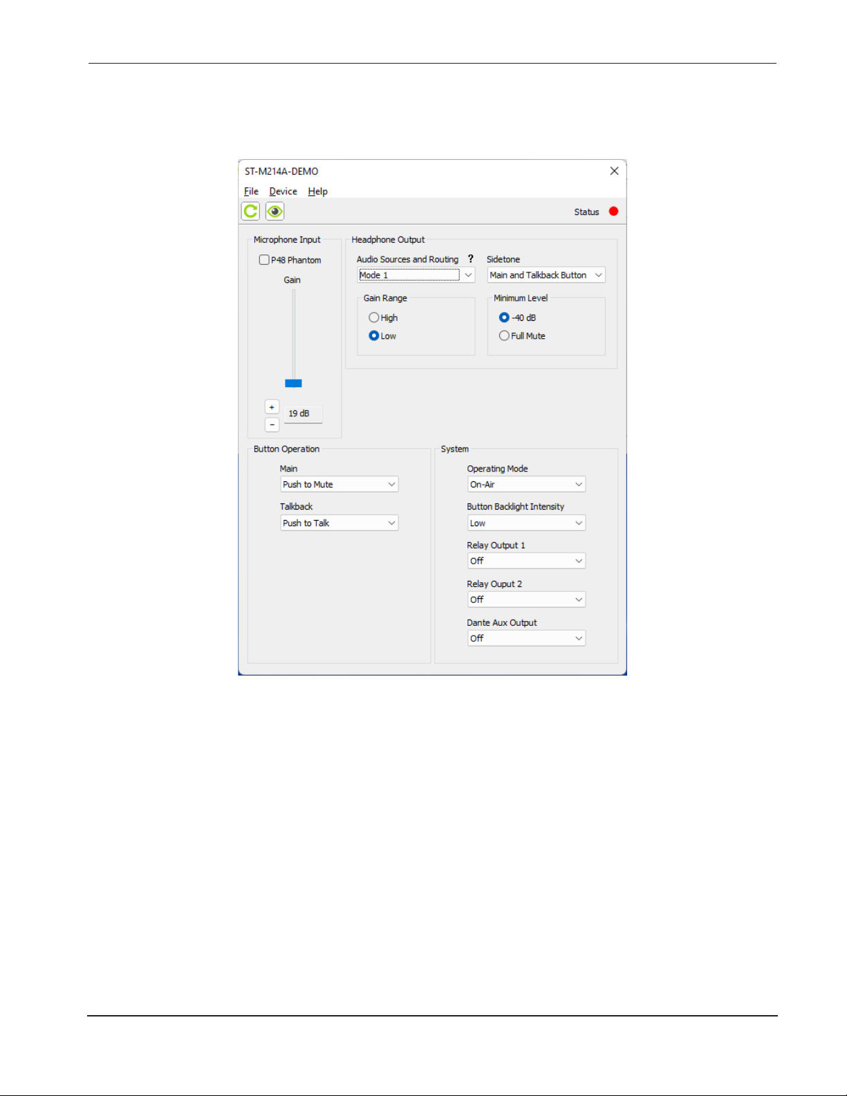
The following conguration selections are available in the STcontroller menu:
UPDATE!UPDATE!
Microphone Input – P48 Phantom Power
Choices are O and On.
STcontroller allows selection of the on/off status of the
microphone input’s P48 phantom power source. The on/
off status is displayed by way of an LED, red in color,
located on the back panel adjacent to the microphone input
connector. Select the status of the P48 source to meet the
needs of the connected microphone.
Microphone Input – Gain
Choices are 19 dB to 64 dB in 3-dB steps.
STcontroller is used to select the gain of the microphone
preamplier. There’s no problem changing the gain setting
while the unit is operating. Small audio clicks or pops might
occur during gain transitions but this shouldn’t be a major
issue as long as associated monitor loudspeakers are
temporarily attenuated or muted.
Model 214A User Guide Issue 2, April 2023
Studio Technologies, Inc. Page 13
To select the correct amount of gain for an application will
probably take some experimentation. The goal is to bring
the microphone’s signal up to the Dante reference level
which Studio Technologies considers to be –20 dBFS (this
is 20 dB below the digital maximum of 0 dBFS). Operating
at this nominal signal level will help ensure that optimal
audio performance is delivered to the destination device
or devices.
There’s no “perfect” gain setting that this guide can
recommend. The two issues that impact the gain setting
are the output sensitivity of the connected microphone and
the acoustical output level of the microphone’s user. With
some headset microphones, such as that in a Sennheiser
HMD 26 or HMD 27, selecting an initial gain setting of 43
or 46 dB would be appropriate. Users who speak loudly
might need to have the gain reduced to 40 or even 37 dB;
quiet users might need 49 or 52 dB of gain.
Page 14

Model 214A
ANNOUNCER’S CONSOLE
Observing the signal level on the device that’s being “fed”
(digitally supplied) by the Model 214A’s Dante main transmitter (output) channel is a good means of checking the
actual signal level as it relates to the conguration of the
microphone preamplier. Most devices have some method
of providing an indication of the digital level, either in the
form of a numerical value, physical or virtual “VU” meter, or
LED-based display. The Studio Technologies’ Model 5202
Dante to Phones and Line Output Interface would also be
an excellent means of monitoring the Model 214A’s output
level. The Model 5202 provides a 2-channel LED level that
is calibrated in dBFS.
A dual-color LED, located on the Model 214A’s back panel
adjacent to the microphone input connector, is provided as
an aid when adjusting the gain of the microphone preampli-
er. It provides a 3-step indication of the output level of the
microphone preamplier. It will light green when the signal
level is –40 dBFS or greater, light in a mix of green and red
when the signal level is –14 dBFS or greater, and light red
only when the signal level is –4 dBFS or greater. When the
gain of the microphone preamplier is set optimally a signal
at a normal level that’s applied to the microphone input will
cause the LED to light green with an occasional peak signal
causing the LED to light both green and red at the same
time. A more conservative gain setting would nd that the
LED would only light green. A gain setting that results in
the LED ever lighting only red would be incorrect. The gain
must be reduced or the audio quality would probably be
severely compromised.
Headphone Output – Audio Sources and
Routing
Choices are Mode 1, Mode 2, Mode 3, Mode 4, and Mode 5.
STcontroller allows selection from among ve headphone
audio source and routing modes. Each mode is distinct
and careful selection will help optimize the Model 214A’s
operation for a range of applications.
Mode 1 – Ch1 L / Ch2 R / Sidetone LR: This mode is provided for on-air applications where two independent audio
sources need to be routed separately to the two headphone
output channels. Dante receiver (input) channel 1 will be
routed to the left headphone output channel and level control A will adjust its level. Dante receiver (input) channel 2
will be routed to the right headphone output channel and
level control B will adjust its level. Level control C will adjust
the level of the sidetone audio as it is sent to both the left
and right headphone output channels.
Mode 2 – Ch1 L Ch2 R / Balance LR / Sidetone LR: This
mode is provided for stereo applications that could include
live music events that are distributed via streaming audio or
by way of an over-the-air broadcast. In these applications
it’s typical to want the user to have a single control to simultaneously adjust the level of a stereo pair while a separate
potentiometer is used to adjust the left/right level balance.
When set for Mode 2, Dante receiver (input) channel 1
will be routed to the left headphone output channel and
Dante receiver (input) channel 2 will be routed to the right
headphone output channel. Level control A will adjust the
level of the input channels as they are sent to both headphone output channels. Level control B will adjust the level
balance between the left and right output channels. Level
control C will adjust the level of the sidetone audio as it is
sent to both the left and right headphone output channels.
Mode 3 – Ch1 L Ch2 R / Ch3 L Ch4 R / Sidetone LR: This
mode can be useful in applications where two stereo signals need to be provided to the user on the left and right
headphone output channels. In this mode, Dante receiver
(input) channels 1 and 2 are routed, respectively, to the left
and right channels of the headphone output. Level control
A adjusts the level of this stereo pair. Dante receiver (input)
channels 3 and 4 are also routed, respectively, to the left
and right channels of the headphone output. Level control
B adjusts the level of this stereo pair as it is sent to the
headphone output channels. Level control C adjusts the
level of the sidetone audio as it is sent to both the left and
right headphone output channels.
Mode 4 – Ch1 L / Ch2 R / Ch3 L Ch4 R: This mode is very
similar to Mode 1 except instead of providing sidetone
another stereo pair can be routed to the left and right headphone output channels. Dante receiver (input) channel 1 is
routed to the left channel of the headphone output. Level
control A adjusts its level. Dante receiver (input) channel
2 is routed to the right headphone output channel and
level control B adjusts its level. A stereo pair can enter the
Model 214A by way of Dante receiver (input) channels 3
and 4. These signals, whose level is adjusted using the
level control C, are sent, respectively, to the left and right
channels of the headphone output.
Mode 5 – Ch1 LR / Ch2 LR / Ch3 L Ch4 R: This mode is a
unique variation where two monaural signals can be routed
to both the left and right headphone output channels while
a stereo input source is routed, in stereo, to the headphone
output channels. Dante receiver (input) channel 1 will be
routed to both the left and right channels of the headphone
output. Its level is controlled by level control A. Dante
receiver (input) channel 2 will also be routed to both the left
and right channels of the headphone output. Its level will be
adjusted using level control B. A stereo pair can enter the
Model 214A by way of Dante receiver (input) channels 3
and 4. These signals will be sent, in stereo, to the left and
right channels of the headphone output. Their level, as a
pair, will be adjusted using level control C.
Issue 2, April 2023 Model 214A User Guide
Page 14 Studio Technologies, Inc.
Page 15

Model 214A
ANNOUNCER’S CONSOLE
Headphone Output – Sidetone
Choices are O, Main Button, Talkback Button, and
Main and Talkback Buttons.
STcontroller allows the Model 214A’s sidetone function
to be congured as desired. Sidetone is audio from the
output of the microphone preamplifier that is sent to
the headphone output channels. This can be important,
allowing the user to “hear” themselves for performance
conrmation and comfort. Making a specic selection from
among the four available modes will depend on the needs
of the application. If a “full mix” is being provided to the
Model 214A’s Dante receiver (input) channels then locally
provided sidetone won’t be needed and the Off mode
should be selected. The user will hear themselves by way
of the audio signals that are arriving via the Dante receiver
(input) channels. If “mix-minus” audio is being supplied
to the Model 214A then selecting one of the headphone
source and routing modes which enables sidetone (modes
1, 2, or 3) can be an important means of establishing user
condence. The selected sidetone mode will determine
exactly when sidetone audio will be sent to the headphone
output channels.
O: In this mode, the sidetone function is not active.
Main Button: In this mode, the sidetone function will be
active whenever the main button function is active and
audio associated with the microphone preamplier is present on the Dante main transmitter (output) channel.
Talkback Button: In this mode, the sidetone function will
be active whenever the talkback button is active and audio
associated with the microphone preamplier is present on
the Dante talkback transmitter (output) channel.
Headphone Output – Minimum Level
Choices are –40 dB or Full Mute.
STcontroller allows selection of the headphone output’s
minimum level. In the –40 dB setting the minimum headphone output level is approximately 40 dB below the
maximum output level; the headphone output will never
fully mute. This ensures that audio signals present on the
selected Dante receiver (input) channels will always be
present on the headphone output channels. In most onair broadcast applications this is the appropriate setting,
ensuring that some level of signal is always present.
When Full Mute is selected moving any level control to its
fully counterclockwise position will cause its associated
channel to fully mute. If a level control is set to serve as a
balance control, moving it to either its fully counterclockwise
or its fully clockwise position will cause the associated signal to mute. Selecting the Full Mute mode may be appropriate for applications where minimizing the chance of audio
“leakage” into an active microphone is important. As an
example, this setting could be useful when the connected
headset or headphones are at times placed on a desk or
tabletop, adjacent to on-air talent.
Note that when level control C, located on the right side of
the front panel, has been congured to control the sidetone
level the conguration of the headphone output minimum
level mode will not impact it. When level control C is used
for sidetone, setting it to its fully counterclockwise position
will always cause the sidetone output level to fully mute.
Button Operation – Main
Choices are Push to Mute, Push to Talk, Latching, Push
to Talk/Tap to Latch, and Push to Mute/Tap to Latch.
Main and Talkback Buttons: In this mode, the sidetone
function will be active whenever the main or talkback but-
STcontroller allows the operating mode of the main button
to be congured. There are ve choices available:
tons are active and audio associated with the microphone
preamplier is present on the Dante main or Dante talkback
transmitter (output) channels.
Push to Mute: If this mode is selected, the main button function will normally be active. The audio signal associated with
the output of the microphone preamplier will be routed to
Headphone Output – Gain Range
Choices are High and Low.
STcontroller is used to select the overall level of the
headphone output channels. The default setting, Low, is
designed so that users with typical audio input sources will
be inclined to set the three rotary level controls at approximately 50% of their rotation. This would be appropriate for
most applications. The High setting would be applicable
in cases where an extreme headphone output level is
required or the level of the audio input sources is lower than
typical. Using the High setting in the former application is
not recommended as hearing damage could result from
exposure to high signal levels.
Model 214A User Guide Issue 2, April 2023
Studio Technologies, Inc. Page 15
the Dante main transmitter (output) channel. Whenever the
main button is pressed this audio signal will not be present
on the Dante main transmitter (output) channel.
Push to Talk: If this mode is selected, the main button function will normally be inactive. The audio signal associated
with the microphone preamplier will not be present on the
Dante main transmitter (output) channel. Whenever the
main button is pressed the audio signal will become active
on the Dante main transmitter (output) channel.
Latching: If this mode is selected, the main button’s function
will alternate between its active and inactive states whenever the main button is pressed. Upon Model 214A power
up the function will be in its inactive state.
Page 16

Model 214A
ANNOUNCER’S CONSOLE
Push to Talk/Tap to Latch: This mode is a combination of the
Push to Talk and Latching modes. It’s similar to the way talk
pushbutton switches function on user stations associated
with broadcast or production intercom systems. If the main
button is pressed and held the main button’s function will be
active. It will stay active until the main button is released. If
the main button is momentarily “tapped” the main button’s
status will change, either from inactive-to-active or from
active-to-inactive. Upon Model 214A power up the main
button function will be in its inactive state.
Push to Mute/Tap to Latch: This mode is a combination of
the Push to Mute and Latching modes. Whenever the main
button is momentarily “tapped” the main button’s status
will change, either from active-to-inactive or inactive-toactive. The audio signal associated with the output of the
microphone preamplier will be routed to the Dante main
transmitter (output) channel. Whenever the main button is
pressed and held this audio signal will not be present on
the Dante main transmitter (output) channel. It will stay
in this condition until the main button is released. Upon
Model 214A power up the main button function will be in
its inactive state.
Button Operation – Talkback
Choices are Push to Talk, Latching, and Push to Talk/
Tap to Latch.
The manner in which the talkback pushbutton switch func-
tions can be congured. There are three mode choices
available.
Push to Talk: If this mode is selected, the talkback function
will normally be inactive and the LED associated with the
talkback button will not be lit. Whenever the talkback button
is pressed the talkback function will become active and
depending on the unit’s conguration, the button’s green
or red LED will light.
Latching: If this mode is selected, the talkback function will
alternate between the active and inactive states whenever
the talkback button is pressed. Upon power up the talkback
function will be in its inactive state and its button LED will
not be lit.
Push to Talk/Tap to Latch: This mode is a combination of
the Push to Talk and Latching modes. It’s similar to the way
talk pushbutton switches function on user stations associated with broadcast or production intercom systems. If the
talkback button is pressed and held the talkback function
will be active. It will stay active until the talkback button is
released. If the talkback button is momentarily “tapped”
the status of the talkback function will change, either from
inactive-to-active or from active-to-inactive. Upon Model
214A power up the talkback button will be in its inactive
state and its LED will not be lit.
System – Operating Mode
Choices are On-Air, Production, and Production with Dim.
The operating mode congures the overall manner in which
the Model 214A operates. Specically, it determines how
the Dante main transmitter (output) channel operates visà-vis the Dante talkback transmitter (output) channel and
whether the headphone output level is reduced during
talkback operation. Understanding how these three modes
impact overall system operation will ensure that correct
operation and maximum usability will occur.
On-Air: When selected to the On-Air mode, the audio signal
on the Dante main transmitter (output) channel will mute
whenever the Dante talkback transmitter (output) channel
is active. The On-Air mode should be selected for all on-air
broadcast applications when it’s imperative that the audio
signal on the Dante main transmitter (output) channel be
muted whenever on-air talent uses the talkback function
to communicate with production personnel.
Production: When the system mode is set for Production,
the audio signal on the Dante main transmitter (output)
channel won’t mute in response to the talkback function
being active. This mode allows the Dante main transmitter
(output) channel to be used, for example, as an additional
Dante talkback transmitter (output). In this way, the Dante
main and talkback transmitter (output) channels can be
used independently, with neither impacting the other. This
also allows the two pushbutton switches and their associated functions to be used simultaneously. When selected
for the correct application, this mode can prove to be very
useful. However, it’s not appropriate for on-air use!
Production with Dim: This mode is identical to the Production mode with the exception that the headphone output
will reduce in level (“dim”) whenever the main or talkback
functions are active. This mode was specically provided
to minimize the chance that acoustical feedback will occur
in applications where the headphone output is connected
to inputs on audio amplifiers or amplified speakers. In
this mode, the level of the headphone output channels is
reduced by 18 dB whenever the main or talkback function
is active. This mode is not appropriate when headphones
are going to be connected to the Model 214A!
System – Button Backlight Intensity
Choices are High and Low.
This conguration choice selects the intensity of the white
LEDs that provide backlighting for the two pushbutton
switches. Low is appropriate when the Model 214A is to
be used in an environment where the ambient light level is
low. High would be appropriate where other light sources in
the physical area may make the main and talkback push-
buttons more dicult to identify. High may also be useful
Issue 2, April 2023 Model 214A User Guide
Page 16 Studio Technologies, Inc.
Page 17

Model 214A
ANNOUNCER’S CONSOLE
when identication markings have been inserted under the
clear lens caps.
System – Relay Output 1
Choices are O, Main Button, Talkback Button, and
Main and Talkback Buttons.
This conguration choice selects when relay output 1 will
be enabled.
O: When relay output 1 is congured for o, the contact
associated with relay output 1 will never close (short). This
setting would be appropriate when relay output 1 is not
being utilized.
Main Button: When relay output 1 is congured for Main
Button, the contact associated with relay output 1 will close
(short) whenever the main button function is active.
Talkback Button: When relay output 1 is configured
for Talkback Button, the contact associated with relay
output 1 will close (short) whenever the talkback button
function is active.
Main and Talkback Buttons: When relay output 1 is cong-
ured for Main and Talkback buttons, the contact associated
with relay output 1 will close (short) whenever the main or
talkback button functions are active.
System – Relay Output 2
Choices are O, Main Button, Talkback Button, and
Main and Talkback Buttons.
This conguration choice selects when relay output 2 will
be enabled.
The exact functioning of the choices for relay output 2 is
identical to those provided for relay output 1.
must be aware that audio from the microphone preamplier
will always be present on this Dante transmitter (output)
channel.
When Tally Tone is selected, a 20 kHz sine wave signal
at a level of –20 dBFS will be present on the Dante aux
transmitter (output) channel whenever the main output
function is active. This is provided as a control signal for
use in REMI/At-Home or other specialized applications. A
20 kHz tone being present on the Dante aux transmitter
(output) will serve as a tally signal indicating that audio can
be present on the Dante main transmitter (output) channel.
Main with 18 kHz Tone is an interesting configuration
choice. Whenever the Dante main transmitter (output)
channel is active the signal on the Dante aux transmitter
(output) channel will consist of a combination (sum or mix)
of audio from the output of the microphone preamplier
and an 18 kHz sine wave tone. In this way, the Dante aux
transmitter (output) can prove to be especially useful for
REMI/At-Home applications. Other products from Studio
Technologies, including the Model 5422A Dante Intercom
Audio Engine and the Model 391 Dante Alerting Unit, can
directly utilize this signal.
Operation
At this point, the microphone, headphone, Ethernet, and,
if required, 12 volts DC power connections should have
been made. The pushbutton labels may have been revised.
The desired conguration should have been made using
the STcontroller software application. The Dante transmitter (output) and Dante receiver (input) channels should
have been routed (subscribed) using the Dante Controller
software application. Normal operation of the Model 214A
can now begin.
System – Dante Aux Output
Choices are O, Hot Mic, Tally Tone, and Main with
18 kHz Tone.
The Dante aux transmitter (output) channel is available
for special applications and is capable of providing a vari-
ety of audio signals. Each conguration choice has been
carefully selected and may prove useful in sophisticated
applications. If the Dante aux transmitter (output) channel
is not going to be utilized then the O mode choice should
be selected.
When Hot Mic is selected, audio associated with the output
of the Model 214A’s microphone preamplier will always be
present on the Dante aux transmitter (output) channel. The
Hot Mic function can be very useful but has the potential for
abuse. By the very nature of a hot mic function, no button
press by the user can cause the audio signal on the Dante
aux transmitter (output) channel to become inactive. Users
Model 214A User Guide Issue 2, April 2023
Studio Technologies, Inc. Page 17
Initial Operation
The Model 214A will begin functioning a few seconds after
its power source is connected. As previously discussed,
the power source can be provided by Power-over-Ethernet (PoE) or an external source of 12 volts DC. If both are
connected, the PoE source will power the unit. Should PoE
subsequently no longer be available uninterrupted operation will continue using the external DC source.
Upon Model 214A power up most of the status and button
backlight LEDs will activate in a test sequence. The PoE,
USB, and SIG/PEAK LEDs, located on the back panel,
will light one after another. On the unit’s top surface, the
two status LEDs and the backlight LED associated with
the main pushbutton switch and the status and backlight
LEDs associated with the talkback pushbutton switch will
momentarily light in sequence. Once that sequence has
completed all the LEDs will begin to function normally.
Page 18

Model 214A
ANNOUNCER’S CONSOLE
The manner in which the LINK/ACT, SYS, and SYNC LEDs
(all located below the etherCON connector) will light depends on characteristics related to the connected Ethernet
signal and the conguration of the unit’s Dante interface.
This will be covered in detail in the next section.
After the power-up sequence has completed the Model
214A will begin normal operation. Depending on the select-
ed conguration one status LED associated with the main
pushbutton switch may be lit. The user is now presented
with two pushbutton switches, three LEDs, and three rotary
controls. These are simple to operate and understand, as
will be described in later sections.
Ethernet, PoE, and Dante Status LEDs
Four status LEDs are located below the etherCON connector on the Model 214A’s back panel. The LINK/ACT LED will
light green whenever an active connection to a 100 Mb/s
Ethernet network has been established. It will ash in response to data packet activity. The PoE LED will light green
whenever Power-over-Ethernet (PoE) associated with the
connected Ethernet signal is providing operating power to
the Model 214A. The SYS and SYNC LEDs display the
operating status of the Dante interface and associated network. The SYS LED will light red upon Model 214A power
up to indicate that the Dante interface is not ready. After a
short interval it will light green to indicate that it is ready to
pass data with another Dante device. The SYNC LED will
light red when the Model 214A is not synchronized with a
Dante network. It will light solid green when the Model 214A
is synchronized with a Dante network and an external clock
source (timing reference) is being received. It will slowly
light on and o green when the Model 214A is part of a
Dante network and is serving as the Leader clock. (This
will not be the normal situation for most applications but is
technically possible.) Note that up to 30 seconds may be
required for the SYNC LED to reach its nal state.
How to Identify a Specic Model 214A
The Dante Controller software application oers an identify
command that can be used to help locate a specic Model
214A. When Identify is selected for a specic unit the button
backlight LEDs will ash. In addition, the SYS and SYNC
LEDs, located directly below the etherCON connector on
the back panel, will slowly ash green. After a few seconds
the identication patterns will cease and normal Model
214A operation will again take place.
Signal Present/Peak LED
A dual-color LED is located on the Model 214A’s back
panel, adjacent to the microphone input connector. It mon-
itors the output of the microphone preamplier, providing a
3-step signal level indication. The LED will light green when
the signal level is –40 dBFS or greater. It will simultaneously
light green and red, appearing orange, when the signal
level is –14 dBFS or greater. The LED will light red when
the signal level is –4 dBFS or greater. During normal operation this LED should light green and when signal peaks
are present will occasionally light both green and red. If
the LED is lit constantly green and red at the same time
the gain of the microphone preamplier most likely should
be reduced. The LED should never light red only as this
would indicate a signal that’s in danger of reaching 0 dBFS
(digital “clipping”). This would indicate that the gain of the
microphone preamplier should be signicantly reduced.
P48 Phantom Power LED
A red LED indicator is located on the back panel adjacent
to the microphone input connector. Labeled P48, it will light
whenever the P48 phantom power source is active and
providing power to the microphone input.
Pushbutton Switches and Status LEDs
Two pushbutton switches are used to control the audio
signals on the main and talkback output channels. The
way each operates depends on the selected conguration.
Three LED indicators are located adjacent to the pushbut-
tons and reect the status of the audio signals associated
with the main and talkback output channels. The pushbuttons’ clear lenses are backlit using white LEDs. The
intensity (brightness) of these LEDs is congured from a
choice of two values, low or high. The backlighting does not
provide an indication of the associated pushbutton’s status
nor do they serve as a tally function, but rather allow the
pushbutton’s labeling and location to be visible in low-light
conditions.
Main Button and LED Indicators
The pushbutton switch that is located on the left side, factory labeled as COUGH, functions according to the selected
conguration. Two LED indicators, located directly above
the pushbutton switch, are associated with the status of the
audio signal on the Dante main transmitter (output) channel. The green LED, located on the right, is lit whenever the
microphone audio signal is connected to the Dante main
transmitter (output) channel. This could be considered as
an “on-air” or “mic-active” indicator. If the Model 214A’s
system mode is congured to On-Air, the red LED, located
on the left, will be lit when the audio signal associated with
Dante main transmitter (output) channel is muted.
If the Model 214A is congured to operate in one of the
production modes, the red LED will never light. This is to
reect the fact that the main pushbutton switch has now
taken on a function similar to that of a talkback pushbutton
switch. To clarify, when the Model 214A is set to either of the
production modes, the red LED will never light; the green
LED will light whenever microphone audio is connected to
the Dante main (transmitter) output channel.
Issue 2, April 2023 Model 214A User Guide
Page 18 Studio Technologies, Inc.
Page 19

Model 214A
ANNOUNCER’S CONSOLE
Main Button Modes
Depending on the selected conguration, there are ve
ways the main pushbutton switch can function:
Push to Mute: If this mode is selected, the audio signal
associated with the Dante main transmitter (output) channel
is normally active. The audio signal will mute whenever the
pushbutton switch is pressed and held.
Push to Talk: If this mode is selected, the audio signal
associated with the Dante main transmitter (output) channel
is normally muted. The audio signal will become active
whenever the pushbutton switch is pressed and held.
Latching: If this mode is selected, the audio signal associated with the Dante main transmitter (output) channel will
alternate between its active and muted states whenever
the pushbutton switch is pressed. Upon power up the audio
signal will be in its muted state.
Push to Talk/Tap to Latch: This mode is a combination of
the Push to Talk and Latching modes. It’s similar to the
way talk pushbuttons function on user stations associated
with broadcast or production intercom systems. If the pushbutton is pressed and held the audio signal associated with
the Dante main transmitter (output) channel will become
active until the pushbutton switch is released. If the pushbutton switch is momentarily “tapped” the audio signal will
change state. Upon Model 214A power up the audio signal
will be in its muted state.
Push to Mute/Tap to Latch: This mode is a combination
of the Push to Mute and Latching modes. Whenever the
main button is momentarily “tapped” its status will alternate between active and muted. When the main button’s
function is active and the main button is pressed and held
the audio signal will mute on the Dante main transmitter
(output) channel. It will stay in this condition until the main
button is released. Upon Model 214A power up the audio
signal will be in its muted state.
Main Output vis-à-vis Talkback Activity
This short section applies only in the case where the Model
214A’s system mode is congured for On-Air and the main
pushbutton mode is set to Latching, Push to Talk/Tap to
Latch, or Push to Mute/Tap to Latch.
Talkback activity will always cause the audio signal associated with the Dante main transmitter (output) channel
to be placed in its muted state. If the audio signal was in
the “latched-on” state when talkback activity began, once
talkback activity ends that state will resume; the audio
signal associated with the Dante main transmitter (output)
channel will again be in its on (“latched”) state.
Talkback Button and LED Indicator
The second pushbutton switch from the left, factory labeled
TALKBACK, controls the audio signal associated with the
Dante talkback transmitter (output) channel. The manner in
which the talkback pushbutton switch functions depends on
the way it has been congured. One LED indicator, green
in color, is located directly above the talkback pushbutton
switch. It will light whenever the microphone audio signal
is connected to its associated Dante talkback transmitter
(output) channel. If the Model 214A’s system mode is
selected for On-Air, whenever the talkback function is active
the audio signal associated with the Dante main transmitter
(output) channel will be placed in its muted state. If the
Model 214A is selected for either of the production modes,
the status of the talkback pushbutton switch will not impact
the status of the audio signal associated with the Dante
main transmitter (output) channel.
Talkback Button Modes
The operation of the talkback pushbutton switch can be
independently congured using the STcontroller software
application. Depending on the selected conguration, there
are three ways the talkback pushbutton switch can function:
Push to Talk: If this mode is selected, the audio signal associated with a Dante talkback transmitter (output) channel is
normally muted. The audio signal will become active whenever the talkback pushbutton switch is pressed and held.
Latching: If this mode is selected, the audio signal associated with a Dante talkback transmitter (output) channel
will alternate between its active and muted state whenever
its pushbutton is pressed. Upon Model 214A power up the
Dante talkback transmitter (output) channels will be in their
muted state.
Push to Talk/Tap to Latch: This mode is a combination
of Push to Talk and Latching. If the pushbutton switch is
pressed and held, the audio signal associated with the
Dante talkback transmitter (output) channel will become
active until the talkback pushbutton switch is released. If
the talkback pushbutton switch is momentarily “tapped” the
audio signal will change state. Upon Model 214A power up
the talkback audio signal will always be in its muted state.
Headphone Output
Three rotary controls (“pots”) are located on the Model
214A’s front panel and are associated with the headphone
output. The way these control’s function will depend on the
conguration of the Audio Sources and Routing parameter
within the STcontroller software application. There are ve
modes available and each is unique. The overall level of
the headphone output is established using the gain range
conguration. Another conguration setting selects whether
the headphone output channels will maintain a minimum
Model 214A User Guide Issue 2, April 2023
Studio Technologies, Inc. Page 19
Page 20

Model 214A
ANNOUNCER’S CONSOLE
output level or can be fully muted. The action of the sidetone
function is also congured using STcontroller.
To understand exactly how the level controls on a specic
Model 214A will function requires knowledge of how that
unit has been congured. Please refer to the Conguration
section for details. It may require a bit of study to fully understand how the controls will function. The author would like to
be able to provide a simple explanation. But there are really
ve simple explanations, one for each conguration choice!
Each level control has a mechanical step (detent) that is
located at the halfway (50%) position of its rotation range.
This is intended to serve as an aid to Model 214A users. In
an ideal installation, setting the controls to their detent position will result in a comfortable headphone output level. The
user, in response to a changing operating environment, can
then move the level controls to get more or less headphone
level as desired. The detent position will always remain as a
useful reference point. To achieve this condition, the audio
level on the appropriate Dante receiver (input) channels
will have to be calibrated as required. This is somewhat
counterintuitive to the usual mentality of just providing the
user with whatever level comes up by default. Spending a
few extra minutes “trimming” the levels of the audio channel
can result in much happier, and more-productive, users.
One of the headphone output modes uses control B, located in the center of the unit, as a level balance function. In
this case, the detent position will send approximately equal
levels to both the left and right headphone output channels.
This is as one would expect from a “stereo” balance control
such as provided in consumer electronic equipment.
When the headphone minimum level conguration is set to
–40 dB, turning a level control to its fully counterclockwise
position will cause the level of its associated headphone
output channel(s) to become 40 dB below maximum.
This ensures that users will never be fully “isolated” from
potentially important cue signals. In addition, when a control
is set to provide a balance function, turning it to either its
fully clockwise or fully counterclockwise position will cause
the level on the applicable headphone output channel to
be 40 dB below its maximum.
If the headphone minimum level conguration is set for Full
Mute, turning a level control to its fully counterclockwise
position will cause the level of the associated headphone
output channel(s) to fully mute. In addition, when a control
is congured to provide a balance function, rotating it to
either its fully clockwise or fully counterclockwise position
will cause the level of the applicable channel to fully mute.
The overall level of the headphone output can be congured as desired for specic applications. In the STcontroller
conguration application this is referred to as the Gain
Range. The default setting, low, is designed so that users
will typically set the rotary controls at approximately 50%
of rotation. The high setting would be applicable in cases
where an extreme headphone output level is required or
the source material that is provided on the Dante receiver
(input) channels is lower than typical.
Sidetone Function Activity
The Model 214A’s sidetone function is used to send
post-microphone-preamplifier audio to the headphone
output as a user conrmation signal. Whether or not the
sidetone function can be active will depend on the con-
guration of the Headphone Output – Audio Sources and
Routing parameter in the STcontroller software application.
Three of the ve available modes enable sidetone. If one
of these three modes is selected, when sidetone audio
will actually be sent to the headphone output will depend
on the conguration of the Headphone Output – Sidetone
parameter in the STcontroller application. The Sidetone
parameter can be congured from among four choices. One
disables sidetone. The other three allow sidetone audio to
be active when the Dante main transmitter (output) channel
is active, to be active when the Dante talkback transmitter
(output) channel is active, or to be active whenever either or
both the Dante main or Dante talkback transmitter (output)
channels are active. Sidetone audio will always be sent to
both the left and right headphone output channels.
USB Interface
A USB type A receptacle and associated status LED is
located on the back panel of the Model 214A. It is labeled
FIRMWARE UPDATE and is used only for updating the
unit’s operating rmware (embedded software). No audio
data of any kind will pass through it. For details, please
refer to the Technical Notes section.
Technical Notes
IP Address Assignment
By default, the Model 214A’s Ethernet interface will attempt
to obtain an IP address and associated network settings
using DHCP (Dynamic Host Configuration Protocol). If
a DHCP server is not detected, an IP address will be
assigned using the link-local protocol. This protocol is
known in the Microsoft® world as Automatic Private IP
Addressing (APIPA). It is also sometimes referred to as
auto-IP (PIPPA). Link-local will assign an IP address in the
IPv4 range of 169.254.0.1 to 169.254.255.254. In this way,
multiple Dante-enabled devices will be connected together
and automatically function, whether or not a DHCP server
is active on the LAN. Even two Dante-enabled devices that
are directly interconnected using an RJ45 patch cord will
correctly acquire IP addresses and be able to communicate
and transport audio.
Issue 2, April 2023 Model 214A User Guide
Page 20 Studio Technologies, Inc.
Page 21

Model 214A
ANNOUNCER’S CONSOLE
As previously discussed, using the Dante Controller software application, the Model 214A’s IP address and related
network parameters can be set for a xed (“static”) conguration. While this is more involved than letting DHCP or
link-local “do their thing,” if xed addressing is necessary
then that capability is available. In this case, it’s highly
recommended that each unit be physically marked, e.g.,
directly labeled using a permanent marker or “console
tape,” with its specic IP address. If knowledge of a Model
214A’s IP address has been misplaced there is no reset
button or other direct method to restore the unit to a default
IP setting.
In the unfortunate event that a device’s IP address is
“lost,” the Address Resolution Protocol (ARP) networking
command can be used to “probe” devices on a network
for this information. For example, within the Windows
OS the arp –a command can be used to display a list of
LAN information that includes MAC addresses and corresponding IP addresses. The simplest means of identifying
an unknown IP address is to create a “mini” LAN with a
personal computer connected directly to the Model 214A.
Then by using the appropriate ARP command the required
“clues” can be obtained.
Optimizing Network Performance
For best Dante audio-over-Ethernet performance a network
that supports VoIP QoS capability is recommended. This
can be implemented on virtually all contemporary managed
Ethernet switches. There are even specialized switches that
are optimized for entertainment-associated applications.
Refer to the Audinate website (audinate.com) for details
on optimizing networks for Dante applications.
Travel Case
For portable applications it may be desirable to store and
transport each Model 214A unit in a protective case. After
much travel with prototype announcer’s console units,
Studio Technologies’ personnel learned to appreciate the
Pelican Model 1450 case. Purchased with the foam interior
option, it does an excellent job of holding one Model 214A
and an external 12 volts DC power supply. Some applica-
tions may benet from selecting a larger case that would
also hold a related headset, cables, etc. An even larger
case could be selected that would hold multiple Model
214A units. Pelican sells their products through a dealer
network, many of which can be located via a web search.
Additional Connectors Locations
Two spare connector locations are provided on the
Model 214A’s back panel. They are labeled A and B. From
the factory they contain blank plates that can be readily
removed and replaced with a variety of XLR-style connectors. The spare connector locations are included so that
a Model 214A can be customized to meet the many specic
needs that arise in broadcast and related audio applications. Expected uses for these locations include adding
a 6- or 7-pin XLR connector to allow direct connection of
a broadcast-style headset. Other uses include creating a
“loop through” or “mult” function for the microphone input
and/or headphone output connections. A number of interface cable assemblies, along with some special-function
kits, are available from Studio Technologies. Please refer
to the company website (studio-tech.com) for details on
what is available.
The spare connector locations are compatible with the Neu-
trik DL-series of connectors. For exibility, XLR versions
are available that provide from three to seven contacts.
For example, a compatible 3-pin female connector would
be Neutrik part number NC3FD-L-1. Another connector is
the NC6FDS-L-1 which is often used to support headsets.
This is a 6-pin female connector with the unique Switchcraft® 6-pin arrangement. Other connectors, such as the
etherCON protected RJ45 and 3-conductor ¼-inch jack,
can be also be installed. The 4-40 thread-pitch hardware
that secures the blank plates to the Model 214A’s back
panel are also intended to secure the installer-provided
alternate connectors.
The Model 214A’s enclosure must be disassembled prior
to installing connectors in the spare locations. Four 6-32
button-head machine screws, two on the bottom front of the
enclosure and two on the back panel, must be removed.
A 5/64-inch hex driver is required. The cover can then be
carefully separated from the chassis, remaining attached
by means of a exible cable assembly. This “ex-cable”
assembly links the main printed circuit board assembly
with the board assembly that contains the pushbutton
switches and LED indicators. Ensure that the ex cable is
not damaged while the Model 214A is being customized.
If connectors are added to the Model 214A’s spare connector locations, adding labels to them can be helpful. For a
great look it is recommended that Brother® P-Touch ¼-inch
(6 mm) labels be created. Tape material that prints white
text on a black background works out well for the Model
214A. The Brother label cassette number TX-3151, white
on black, is appropriate for use with many of their printers.
3-Position Headers
In addition to the spare connector locations on the back
panel, provision has been made to allow easy interconnection with the Model 214A’s printed-circuit-board-mounted
input and output connectors. This was accomplished by
including several 3-position male header connectors on
the Model 214A’s circuit board. These headers, on 0.1-inch
centers, are wired in parallel with some of the Model 214A’s
connectors. This “no solder” solution makes customizing
Model 214A User Guide Issue 2, April 2023
Studio Technologies, Inc. Page 21
Page 22

Model 214A
ANNOUNCER’S CONSOLE
a Model 214A a simple process. The headers, located on
the Model 214A’s main printed circuit board assembly, are
Molex® part number 22-23-2031. They mate with Molex
housing number 22-01-3037. To make the interconnection,
separate crimp terminals are attached to three loose wires
and then “snapped” into the appropriate housing. Molex
part number 08-50-0114 species crimp terminals that are
appropriate for 22-to-30-gauge wires. These terminals
are available worldwide from sources such as Digi-Key
(digikey.com).
To make the process of connecting to the Model 214A’s
headers a simple task, an interface cable kit, part number 31087, is available from Studio Technologies. Each
kit includes ve cable assemblies and a length of heat-
shrinkable tubing. Each cable assembly consists of a mating connector with three color-coded wires attached. These
wires, approximately 12 inches in length, allow convenient
soldering to a connector selected to be installed in a spare
location on the Model 214A’s back panel. For reference,
Studio Technologies selected gray as the wire color for
pin 1, yellow as the wire color for pin 2, and blue as the
wire color for pin 3.
Interface cable kit 31987 includes a length of heat-shrinkable tubing so that the connector terminals or “solder
cups” can be insulated from each other. It will also provide
some strain relief to the solder joints. Be certain to slip the
desired length of tubing over the wire prior to soldering a
connection! (If the writer had a dollar for every time where
he forgot to put tubing on a wire (or slip on a connector
shell) before making a solder connection...)
Most of the 3-position headers on the Model 214A’s main
circuit board assembly are located close to their related
input or output connectors. Other headers provide access
to functions such as the relays or the contact closure inputs.
For details on the headers please refer to Appendix B.
Contact Closure Input Connections
Provision has been made on the Model 214A’s main printed
circuit board assembly to allow external switches or contact closures to control the status of the microphone audio
signal as it is sent to the Dante main and Dante talkback
transmitter (output) channels. One 3-position header is
provided to access to the circuitry associated with those
functions. Refer to Appendix B for connection details.
The input circuitry for the two functions is “active low,” with
a 3.4 k ohm resistor connected to +3.3 volts DC to act as
a pull up. A combination of resistors and capacitors provide
ESD protection.
Relay Contacts
The Model 214A provides two normally open (not shorted)
relay contacts for use in specialized applications. The action
of each can be congured using the STcontroller software
application. Some “head scratching” or “brainstorming”
should lead to a number of interesting ways to take
advantage of the relay contacts. Applications could include
keying wireless transmitters, activating “on-air” lights, and
muting loudspeaker systems. To utilize the relay contacts
does require the talents of a qualied technician. This is because the Model 214A’s enclosure must be disassembled
and the desired wiring scheme implemented. For detailed
information on interfacing with the relay contacts refer to
Appendix B.
Pushbutton Backlighting
From the factory, white LEDs are installed within the two
pushbutton housings. These LEDs provide illumination
(“backlighting”) of the pushbutton switches. This may prove
useful for applications where adequate room lighting is not
available. It’s important to note that the pushbutton lighting
does not provide a tally function; it is intended to illuminate
the pushbutton’s clear lens and associated labeling. The
LED intensity does not change as its associated button is
pressed.
The lamp socket in each of the pushbutton housings was
originally designed to allow insertion of a pluggable T-1 bipin incandescent bulb. They are also compatible with the
more modern leaded T-1 LEDs. At of the time of writing
this guide, the specic LED used at the factory is the Kingbright WP7104QWC/D. If backlighting is not desired, it’s
easy to remove the LED lamps. The mating socket in each
pushbutton assembly is accessed by carefully removing
the pushbutton’s lens cap, graphic label, and frosted lens.
Once this is done, carefully pull on the body of the LED and
it will pull out of the socket. (A pair of needle-nose pliers or
tweezers may be required to perform this task.)
If an LED needs to be replaced note that it is typically a
polarized device. If upon insertion it does not light, simply
remove the LED, rotate it 180 degrees, then re-insert it
into the socket.
Application Firmware Update Procedure
It’s possible that updated versions of the application rmware (embedded software) that is utilized by the Model
214A’s microcontroller (MCU) integrated circuit will be released to add features or correct issues. Refer to the Studio
Technologies’ website for the latest application rmware le.
The unit has the ability to load a revised le into its MCU’s
nonvolatile memory by way of a USB flash drive. The
Model 214A implements a USB host function that directly
supports connection of a standard USB ash drive. The
Issue 2, April 2023 Model 214A User Guide
Page 22 Studio Technologies, Inc.
Page 23

Model 214A
ANNOUNCER’S CONSOLE
Model 214A’s MCU updates its application rmware using
a le named M214AvXrXX.stm where the Xs are decimal
digits that represent the actual rmware version number.
The update process begins by preparing a USB ash drive.
The ash drive doesn’t have to be empty (blank) but must
be in the personal-computer-standard FAT32 format. The
USB interface in the Model 214A is compatible with USB
2.0-, USB 3.0-, and USB 3.1-compliant ash drives. Save
the new application rmware le in the root directory of the
ash drive with a name of M214AvXrXX.stm where the
XrXX is the actual version number. Studio Technologies will
supply the application rmware le inside of a .zip archive
le. The name of the zip le will reect the application le’s
version number and will contain two les. One le will be
the actual application le and the other a readme (.txt) text
le. It’s recommended that the readme (.txt) le be reviewed
as it will contain details about the associated application
rmware. The application rmware le inside of the zip le
will adhere to the required naming convention so that it can
be directly copied to the ash drive. Once ready, the USB
ash drive should be inserted into the USB host interface
by way of the USB type A receptacle that is located on the
Model 214A’s back panel. The unit must then be power
cycled; rst powered o and then again powered on. At
this point, the application le located in the root folder of
the USB ash drive will automatically load. The precise
steps required will be highlighted in the next paragraphs.
To install the rmware le, follow these steps:
1. Remove power from the Model 214A. This will entail
removing the Ethernet connection if it is providing PoE
power and/or removing the external source of 12 volts
DC if that is being used.
2. Insert the prepared USB flash drive into the Model
214A’s USB receptacle, located on the back panel of
the unit.
3. Apply power to the Model 214A. Power can be provided
by Power-over-Ethernet (PoE) associated with a connected Ethernet signal or can be from an external 12
volts DC source.
4. The Model 214A will run a “boot loader” program that
will immediately load the new application (M214AvXrXX.
stm) le. The loading process typically takes approxi-
mately 10 seconds. During this time period, the LED,
located below the USB receptacle, will slowly flash
green. Once the entire loading process is over, the
Model 214A will restart using the newly loaded appli-
cation rmware.
5. At this time, the Model 214A will be functioning with
the newly loaded application firmware and the USB
flash drive can be removed. But to be conservative,
remove the PoE Ethernet connection or 12 volts DC
power source rst and then remove the USB ash drive.
Re-connect the PoE Ethernet connection or the 12 volts
DC power source to restart the unit.
6. Using STcontroller, conrm that the desired application
rmware version has been correctly loaded.
Note that upon power being applied to the Model 214A,
if a connected USB ash drive doesn’t have the correct
application le (M214AvXrXX.stm) in its root folder no
harm will occur. Upon power up the LED, located below
the USB receptacle on the back panel, will rapidly ash
green for a few seconds to indicate this condition and
then normal operation using the unit’s existing application
rmware will begin.
Ultimo Firmware Update
As previously discussed, the Model 214A implements
its Dante connectivity using the Ultimo integrated circuit
from Audinate. The STcontroller or Dante Controller software applications can be used to determine the version
of Dante rmware (embedded software) that resides in
this integrated circuit. The Dante firmware (embedded
software) residing in the Ultimo can be updated by way
of the Model 214A’s Ethernet port. Performing this update
process is easily accomplished using an automated method
called Dante Updater that’s included as part of the Dante
Controller application. This application is available, free of
charge, from the Audinate website (audinate.com). The
latest Model 214A rmware le should be available as part
of Audiante’s product library database. The Dante le will
also be available on the Studio Technologies’ website with
a name in the form of M214AvXrXrX.dnt. By being available on Audinate’s database will allow the Dante Updater
software application that is included with Dante Controller
to automatically query and, if required, update the Model
214A’s Dante interface.
Restoring Factory Defaults
A command within the STcontroller application will allow
the Model 214A’s conguration selection to be reset to its
factory default values. From within STcontroller select the
specic Model 214A unit for which you want to restore its
defaults. Select the Device tab and then select the Factory Defaults feature. Then click on the OK box. Refer to
Appendix A for a list of the Model 214A’s factory default
values.
Model 214A User Guide Issue 2, April 2023
Studio Technologies, Inc. Page 23
Page 24

Model 214A
ANNOUNCER’S CONSOLE
Specications
Power Sources:
Power-over-Ethernet (PoE): class 2 (low power,
≤6.49 watts) per IEEE 802.3af
DC Input: 10 to 18 volts DC, 290 mA maximum at
12 volts DC (can be powered by optional PS-DC-02)
Network Audio Technology:
Type: Dante audio-over-Ethernet
AES67-2018 Support: yes, on/o selectable
Dante Domain Manager (DDM) Support: yes
Bit Depth: up to 24
Sample Rates: 44.1 or 48 kHz
Pull Up/Down Support: none
Dante Transmitter (Output) Channels: 3 (Main,
Talkback, Aux)
Dante Receiver (Input) Channels: 4
Dante Audio Flows: 4; 2 transmitter, 2 receiver
Analog to Dante Equivalent: an analog input signal at a
level of –36 dBu and microphone preamplier gain congured for 40 dB will result in a Dante transmitter (output)
level of –20 dBFS
Network Interface:
Type: 100BASE-TX, Fast Ethernet per IEEE® 802.3u
(10BASE-T and 1000BASE-T (GigE) not supported)
Data Rate: 100 Mb/s (10 Mb/s and 1000 Mb/s Ethernet
not supported)
Microphone Input:
Compatibility: dynamic or phantom-powered
microphones
Type: balanced, capacitive coupled
Impedance: 3.7 k ohms, nominal
CMRR: >76 dB, 20 Hz to 20 kHz, 40 dB microphone pre-
amplier gain
Gain Range: 19 to 64 dB, adjustable in 3-dB steps
Frequency Response: 20 Hz to 20 kHz, +0/–1 dB,
microphone input to Dante output
Distortion (THD+N): 0.004%, measured at 1 kHz,
–36 dBu mic input, 40 dB microphone preamplier gain
Dynamic Range: >109 dB, 40 dB microphone
preamplier gain, A-weighted
EIN: –123 dBu, 22 kHz bandwidth, 64 dB microphone
preamplier gain, 150 ohms source resistance
Phantom Power: P48 per IEC 61938 P48 standard,
on/o selectable, 45 volts DC nominal
Headphone Output:
Type: 2-channel
Compatibility: intended for connection to stereo
(dual-channel) or monaural (single-channel) headphones,
headsets, or earpieces with nominal impedance of 50
ohms or greater
Maximum Output Voltage: 3.0 Vrms, 1 kHz, 150 ohm
load
Frequency Response: 20 Hz to 20 kHz, ±1 dB
Distortion (THD+N): <0.025%, measured at 1 kHz,
0 dBu output
Dynamic Range: >109 dB, A-weighted
Tone:
Use: provides support for tone operated (TOX) IFB
function on devices such as Studio Technologies’ Model
5422A Dante Intercom Audio Engine
Type: sine wave
Frequency: 18 kHz ± 0.1 Hz
Level: –20 dBFS
Distortion: <0.01% THD+N
Remote Control Inputs: 2
Functions: mimics the action of the main and talkback
button functions
Type: active low, 1 mA maximum, input pulled up to
3.3 volts DC via 3.4 k ohm resistors
Access: requires user-implemented connector scheme
Relay Contacts: 2
Functions: congurable, can follow status of the main,
talkback, or main and talkback functions
Type: form A (normally open, not shorted), solid-state
Rating: 100 mA, 60 volts AC/DC, maximum
Contact Resistance: 16 ohms, maximum
Access: requires user-implemented connector scheme
Connectors:
Microphone Input: 3-pin female XLR
Headphone Output: ¼-inch 3-conductor jack
Ethernet: Neutrik NE8FBH etherCON RJ45 receptacle
DC Input: 4-pin male XLR (pin 1 negative, pin 4 positive)
USB: type A receptacle (used only for updating rmware)
Spare Connector Locations: 2
Allows Studio Technologies’ option modules to be
installed. Also compatible with Neutrik NC*D-L-1
connectors (*=3F, 3M, 5M, 6F, 6FS, etc.).
Issue 2, April 2023 Model 214A User Guide
Page 24 Studio Technologies, Inc.
Page 25

Model 214A
ANNOUNCER’S CONSOLE
Conguration: requires Studio Technologies’
STcontroller software application
Software Updating: USB ash drive for updating application rmware; Dante Updater application for updating
Dante interface rmware
Environmental:
Operating Temperature: 0 to 50 degrees C (32 to
122 degrees F)
Storage Temperature: –30 to 70 degrees C (–22 to
158 degrees F)
Humidity: 25 to 85%, non-condensing
Altitude: not characterized
Dimensions (Overall):
5.6 inches wide (14.2 cm)
3.3 inches high (8.4 cm)
8.5 inches deep (21.6 cm)
Deployment: intended for tabletop applications
Weight: 2.7 pounds (1.2 kg)
Specications and information contained in this
User Guide subject to change without notice.
Model 214A User Guide Issue 2, April 2023
Studio Technologies, Inc. Page 25
Page 26

Model 214A
ANNOUNCER’S CONSOLE
Appendix A: STcontroller Default Conguration Values
Microphone Input – P48 Phantom: O (box not checked)
Microphone Input – Gain: 19 dB
Headphone Output – Audio Sources and Routing: Mode 1
Headphone Output – Sidetone: Main and Talkback Buttons
Headphone Output – Gain Range: Low
Headphone Output – Minimum Level: –40 dB
Button Operation – Main: Push to Mute
Button Operation – Talkback: Push to Talk
System – Operating Mode: On Air
System – Button Backlight Intensity: Low
System – Relay Output 1: O
System – Relay Output 2: O
System – Dante Aux Output: O
Issue 2, April 2023 Model 214A User Guide
Page 26 Studio Technologies, Inc.
Page 27

Model 214A
ANNOUNCER’S CONSOLE
Appendix B: 3-Pin Header Connector Details
The following list provides details on the 3-pin header connectors located on the Model 214A’s printed
circuit board. Shown are both reference numbers and associated functions.
P2: Microphone Input
Pin 1: Common
Pin 2: High (+)
Pin 3: Low (–)
P5: Headphone Output
Pin 1: Common
Pin 2: Left Channel (Tip)
Pin 3: Right Channel (Ring)
P6: DC Output
Pin 1: Common
Pin 2: 10-18 volts DC Out
Pin 3: Not Used
P7: Relay Contact 1
Pin 1: Common
Pin 2: Normally Open
Pin 3: Normally Open
Note: Pin 2 connects (closes or shorts) to Pin 3 when the congured function or functions active.
P8: Relay Contact 2
Pin 1: Common
Pin 2: Normally Open
Pin 3: Normally Open
Note: Pin 2 connects (closes or shorts) to Pin 3 when the congured function or functions active.
P10: Contact Closure Input – Main
Pin 1: Common
Pin 2: Main Pushbutton Switch
Pin 3:Not Used
P11: Contact Closure Input – Talkback
Pin 1: Common
Pin 2: Talkback Pushbutton Switch
Pin 3: Not Used
Model 214A User Guide Issue 2, April 2023
Studio Technologies, Inc. Page 27
 Loading...