

Page 1

Model 206 Announcer’s Console
User Guide
Issue 1, April 2018
This User Guide is applicable for serial numbers
M206-00151 and later with application firmware 1.1 and later
Copyright © 2018 by Studio Technologies, Inc., all rights reserved
www.studio-tech.com
50646-0418, Issue 1
Page 2

This page intentionally left blank.
Page 3

ANNOUNCER’S CONSOLE
MODEL 206
Table of Contents
Revision History ........................................................... 4
Introduction ................................................................... 5
Getting Started ............................................................. 10
Operation ...................................................................... 19
Technical Notes ............................................................ 23
Specifications ............................................................... 28
Appendix A: Model 206 Block Diagram ........................ 29
Model 206 User Guide Issue 1, April 2018
Studio Technologies, Inc. Page 3
Page 4

ANNOUNCER’S CONSOLE
Revision History
Issue 1, April 2018:
1. Initial release.
MODEL 206
Issue 1, April 2018 Model 206 User Guide
Page 4 Studio Technologies, Inc.
Page 5
ANNOUNCER’S CONSOLE
MODEL 206
Introduction
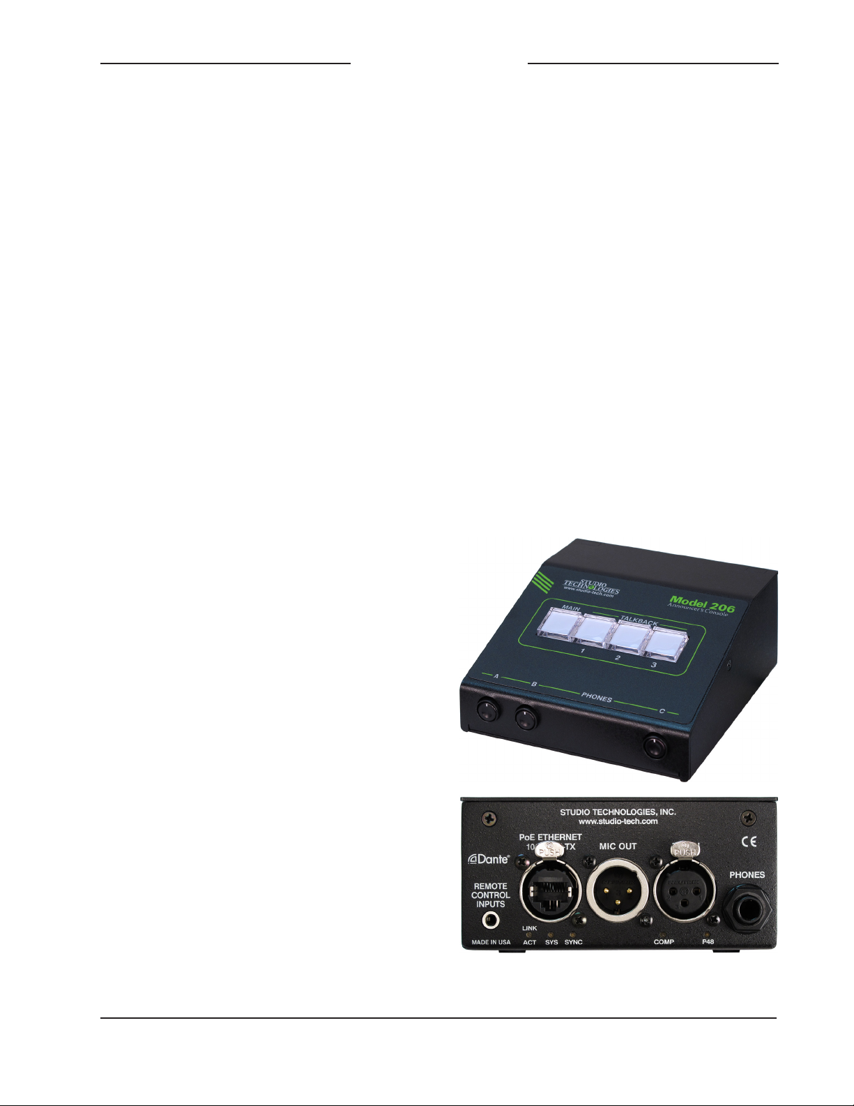
The Model 206 Announcer’s Console
offers a unique combination of analog and
digital audio resources for use in broadcast
sports, eSports, live event, entertainment,
and streaming broadcast applications.
The unit is housed in a compact, rugged
steel enclosure that’s intended for tabletop use. Calling the Model 206 “cute” or
“cool” would be accurate; its nicely proportioned but diminutive size makes it ideal
for use in space-constrained locations.
The Model 206 supports Dante® audioover-Ethernet digital media technology
with AES67 compatibility for integration
into contemporary applications. The unit is
extremely simple to deploy, is “pro” quality
throughout, and provides an intuitive user
experience. The Model 206’s audio quality
is excellent, with low distortion, low noise,
and ample headroom. Careful circuit
design and rugged components ensure
long, reliable operation.
of many applications. STcontroller, compatible with version 7 and later of the
Windows® operating system, is a fast and
simple means of confi
the unit’s operating parameters.
rming and revising
Applications
The Model 206 on its own can provide an
“all-Dante” solution for one on-air talent
location. A wide range of applications can
be supported, including sports and entertainment TV and radio events, streaming
broadcasts, corporate and government AV
installations, and post-production facilities.
The unit’s small size makes it ideal for livesports applications, such as basketball,
where physical space for personnel is very
limited. Four Dante receiver (audio input)
channels supply the user with their talent
cue (IFB) signals. Should the cue signal
The Model 206 integrates directly into both
Dante audio-over-Ethernet and standard
analog audio environments. With just a
Power-over-Ethernet (PoE) connection, a
microphone, and a pair of headphones or
an earpiece, a complete broadcast on-air
position can be created. And by using the
Model 206’s microphone output a direct
connection to an analog microphone-level
input on an associated camera, remote I/O
interface, or audio console can be supported. Two remote control inputs allow external switches or contact closures to activate
the main and/or talkback button functions.
Model 206 operating features are configured using the STcontroller personal
computer software application. An extensive set of parameters allows the unit’s
functions to be tailored to meet the needs
Figure 1. Model 206 Announcer’s Console front
and rear views
Model 206 User Guide Issue 1, April 2018
Studio Technologies, Inc. Page 5
Page 6

ANNOUNCER’S CONSOLE
MODEL 206
be “mix-minus” an integrated sidetone
function can provide the user with a microphone confidence signal. Four Dante audio
output channels, one designated as main
and three named talkback, are routed via
an associated local-area network (LAN) to
inputs on Dante-compatible devices. Four
pushbutton switches, main and three talkback, provide the user with direct control
over audio routing. The audio switching
is performed in the digital domain and is
virtually “click-free.”
By providing the main audio signal in two
forms, Dante digital audio and analog
microphone level, the Model 206 makes
integration into a wide range of on-air environments easy to accomplish. And with the
three talkback audio channels available as
Dante output channels, routing to inputs
on a variety of devices, such as matrix
intercom systems, audio consoles, and
monitor loudspeaker systems, is simple
and flexible.
Some applications may benefit from not
utilizing the Model 206’s Dante main output channel. This typically won’t be an issue of inadequate audio quality but rather
a need to match work-flow requirements.
For example, for lip-sync or transmission
purposes it may be optimal to have the
on-air audio transported as an embedded
signal along with the associated camera
video. Alternately, all on-air audio sources
may need to connect to inputs on an audio
console or console-related I/O unit. Supporting these scenarios is not a problem
as the Model 206 supplies a microphone
output connection that’s specifically intended for this purpose. Simply connect the
unit’s microphone output connection to the
desired analog input, such as the mic/line
input on an ENG-style camera—that’s it!
The circuitry associated with the Model
206’s analog microphone output is very
simple, essentially a passive path that
routes a signal connected to the microphone input connector directly to the
microphone output connector. A solid-state
circuit, in series with the mic in-to-mic out
path, allows muting of the signal on the
microphone output connector whenever
the Dante main output channel is muted.
Having both the Dante main output and the
microphone outputs work in tandem can
be a valuable resource, allowing one to
serve as the primary on-air signal source
while the other serves as the backup.
Setup and Operation
Set up, configuration, and operation of
the Model 206 is simple. An etherCON®
RJ45 jack is used to interconnect with a
standard twisted-pair Ethernet port associated with a PoE-enabled network switch.
This connection provides both power and
bidirectional digital audio. A broadcast
headset or handheld (“stick”) microphone
can be directly connected to the unit’s
3-pin XLR mic input connector. The input
is compatible with dynamic or condenser
microphones. The integrated P48 phantom power source provides support for a
wide range of condenser microphones.
A 3-pin XLR microphone output connector provides a “direct mic out” function
for integration with microphone inputs on
related devices. Stereo headphones, the
headphone connections from a stereo or
monaural headset, or even a monaural
earpiece can be connected to the phones
output jack. External switches or contact
closures can be connected to the Model
206’s remote control inputs to allow activation of button functions. The STcontroller
software application is used to configure
the wide range of Model 206 operating
Issue 1, April 2018 Model 206 User Guide
Page 6 Studio Technologies, Inc.
Page 7

ANNOUNCER’S CONSOLE
MODEL 206
parameters. This allows the unit’s performance to be optimized to meet the needs
of specific applications.
The user is presented with four pushbutton
switches and three push-in/push-out rotary
level potentiometers This makes it easy to
control the status of the main and talkback
outputs as well as adjusting the signals that
are sent to the headphone channels.
Ethernet Data and PoE
The Model 206 connects to a local area network (LAN) by way of a standard 100 Mb/s
twisted-pair Ethernet interface. The physical
100BASE-TX interconnection is made by
way of a Neutrik® etherCON RJ45 connector. While compatible with standard RJ45
plugs, etherCON allows a ruggedized and
locking interconnection for harsh or highreliability environments.
The Model 206’s operating power is provided by way of the Ethernet interface using
the 802.3af Power-over-Ethernet (PoE)
standard. This allows fast and efficient interconnection with the associated data network.
To support PoE power management, the
Model 206’s PoE interface enumerates
(reports) to the power sourcing equipment
(PSE) that it’s a class 2 (low power) device.
If a PoE-enabled Ethernet port can’t be
provided by the associated Ethernet switch
a low-cost PoE midspan power injector can
be utilized.
Dante Audio-over-Ethernet
Audio data is sent to and received from
the Model 206 using the Dante audio-overEthernet media networking technology. As
a Dante-compliant device, the Model 206’s
four Dante transmitter (audio output) channels and four Dante receiver (audio input)
channels can be assigned (routed or “subscribed”) to other devices using the Dante
Controller software application. The Dante
transmitter and receiver channels are limited to supporting four Dante flows, two in
each direction. The digital audio’s bit depth
is up to 24 with a sampling rate of 44.1 or
48 kHz. Two bi-color LEDs provide an indication of the Dante connection status. An
additional LED displays the status of the
associated Ethernet connection.
The Model 206 is compatible with the
AES67 interoperability standard. In this
mode the four transmitter (output) channels will function in multicast; unicast is not
supported. In addition, the unit is compatible with the Dante Domain Manager™
(DDM) software application.
Audio Quality
The Model 206’s audio performance is
completely “pro.” A low-noise, wide dynamic-range microphone preamplifier and
associated voltage-controlled-amplifier
(VCA) dynamics controller (compressor)
ensures that mic input audio quality is
preserved while minimizing the chance of
signal overload. The output of the microphone preamp and compressor is routed
to an analog-to-digital conversion (ADC)
section that supports sampling rates of
44.1 and 48 kHz with a bit depth of up to
24. The audio signal, now in the digital domain, routes through a 32-bit microprocessor and on to the Dante interface section
where it is packetized and prepared for
transport over Ethernet.
Audio input signals arrive via the four
Dante receiver channels and pass into the
Model 206’s microprocessor. The supported sampling rates are 44.1 and 48 kHz
with a bit depth of up to 24. Channel routing, headphone level control, and sidetone
creation are performed within the digital
domain. This provides flexibility, allows
Model 206 User Guide Issue 1, April 2018
Studio Technologies, Inc. Page 7
Page 8

ANNOUNCER’S CONSOLE
MODEL 206
precise control, and keeps the three level
potentiometers from having to directly
handle analog audio signals. The audio
channels destined for the phones outputs
are sent to a high-performance digital-toanalog converter and then on to robust
driver circuitry. High signal levels can be
provided to a variety of headsets, headphones, and earpieces.
Configuration Flexibility
The Model 206 can be configured to meet
the needs of specific applications and user
preferences. All configuration choices are
performed using the STcontroller personal
computer software application which is
compatible with version 7 and later of the
Windows operating systems. There are no
mechanical switch settings or button-press
sequences required to configure how the
unit functions. Selectable parameters
include microphone preamplifier gain, P48
phantom power on/off, button operation,
remote control inputs, headphone output
mode, sidetone operation, and overall unit
operation. The gain of the microphone
preamplifier can be selected from among
four choices. This allows the Model 206
to match the output sensitivity of a range
of handheld and headset-associated
microphones. A low-noise source of P48
phantom power can be enabled if required
to support condenser (capacitor) microphones.
The main and talkback pushbutton switches can be individually configured. The
main button can be selected to operate
from among four modes while the talkback buttons can be selected from among
three. These choices allow the Model
206’s operation to be tailored to meet the
specific needs of many applications. As an
example, for on-air sports applications the
main button would typically be configured
to provide a push to mute (cough) function.
The microphone signal on the Dante main
output channel and the microphone output
connector would remain active unless the
talent needs to momentarily disable it. The
talkback buttons would most likely be set
to their push to talk modes as their use
would be intermittent.
The Model 206 provides two remote control inputs. Configuration choices allow
these to be assigned to work in parallel
with the main, talkback 1, talkback 2, or
talkback 3 pushbutton switches. In this
way activation of a remote control input
will emulate a user pressing its associated
pushbutton switch.
The audio sources and the way in which
they are assigned to the headphone output
channels can be configured from among
five choices. These unique choices allow
almost any required headphone monitoring situation to be implemented. Whether
for use in on-air sports, an awards show
broadcast, or as a production support tool,
the Model 206 should be able to achieve
the desired configuration.
Following the mode number is an abbreviated description of what signal or signals
are assigned to the three potentiometers
(pots) and on to the two headphone output
channels. The potentiometers are labeled
A, B, and C, as can be seen in Figure 1
of this guide. The format would equate to
Mode x – pot A/pot B/pot C where x equals
the mode number.
• Mode 1 – Ch1L/Ch2R/SidetoneLR:
Provided for broadcast applications
where two monaural channels of talent cueing audio (“IFB”) need to be
independently sent to the left and right
headphone output channels. It would be
Issue 1, April 2018 Model 206 User Guide
Page 8 Studio Technologies, Inc.
Page 9

ANNOUNCER’S CONSOLE
MODEL 206
common for program audio with director
interrupt to enter the Model 206 by way
of Dante input (receiver) channel 1 and
be sent to the left headphone output.
Program-only audio, entering the unit by
way of Dante input channel 2, would be
sent to the right headphone output. Pots
A and B are used to adjust the level of
those signals. Pot C is used for the sidetone function where microphone audio is
sent to both the left and right channels of
the headphone output.
• Mode 2 – Ch1LCh2R/BalanceLR/
SidetoneLR: Intended for applications
where a stereo signal enters the Model
206 by way of Dante inputs 1 and 2 and
is routed in stereo to the left and right
channels of the headphone output. In
this mode pot A controls the overall level
of this stereo signal and the pot B controls its left/right level balance. Pot C is
used by the sidetone function.
• Mode 3 – Ch1LCh2R/Ch3LCh4R/
SidetoneLR: Allows two stereo signals
to be routed as stereo pairs to the two
headphone output channels. In this
mode pot A adjusts the level of the
stereo pair entering the unit by way of
Dante inputs 1 and 2 while pot B adjusts
the level of the stereo pair entering on
Dante inputs 3 and 4. Pot C is used by
the sidetone function.
• Mode 4 – Ch1L/Ch2R/Ch3LCh4R:
Allows two monaural input signals to
be independently routed to the left and
right headphone output channels. These
audio signals would enter the Model 206
by way of Dante input channels 1 and 2.
Pots A and B are used to control the
levels of the signals as they are sent
to the left and right headphone output
channels. A stereo input signal, entering
the unit by way of Dante inputs 3 and
4, are routed to the left and right headphone outputs. The level of this stereo
pair is controlled by pot C.
• Mode 5 – Ch1LR/Ch2LR/Ch3LCh4R:
Allows two monaural input audio channels to be sent to both the left and right
headphone output channels. Dante
inputs 1 and 2 are used to bring these
audio signals into the Model 206. Pots
A and B are used to control the level of
the signals as they are sent to the headphone output channels. Pot C is used to
control the level of a stereo input signal
as it is routed to the left and right channels of the headphone output. This stereo pair enters the unit by way of Dante
inputs 3 and 4.
The integrated sidetone function can be
configured to operate from among four
choices. This allows audio associated with
the microphone input and microphone
preamplifier to be returned to the headphone output. This is important as different
applications may provide a “full mix” or a
“mix-minus” talent cue signal. If a full mix
cue signal is provided then sidetone audio
will not be needed and the function can be
disabled. In the case where a mix-minus
signal is present, providing the user with
sidetone at the appropriate time(s) can
be an important means of confirming the
signal that’s coming from the connected
microphone.
The headphone gain range configuration helps to provide an optimized audio
level to Model 206 users. The appropriate
setting will depend on the specific audio
sources provided to the unit as well as
user preference.
Model 206 User Guide Issue 1, April 2018
Studio Technologies, Inc. Page 9
Page 10

ANNOUNCER’S CONSOLE
MODEL 206
Three system modes select the overall
way in which the Model 206 functions. The
on-air mode is optimized for applications
where users will be on-air talent that must
maintain strict separation between on-air
and production audio channels. Other
applications will benefit from the two
available production modes.
Future Capabilities and
Firmware Updating
The Model 206 was designed so that
its capabilities and performance can be
enhanced in the future. A USB connector,
located on the unit’s main circuit board
(underneath the unit’s cover), allows the
application firmware (embedded software)
to be updated using a USB flash drive.
The Model 206 uses the Audinate Ultimo™
integrated circuit to implement the Dante
interface. The firmware in this integrated
circuit can be updated via the Ethernet
connection, helping to ensure that its
capabilities remain up to date.
Getting Started
What’s Included
Included in the shipping carton are a
Model 206 Announcer’s Console and a
printed copy of this guide. As a device that
is Power-over-Ethernet (PoE) powered, no
external power source is provided. In most
applications an Ethernet switch with PoE
capability will be utilized. If that’s not
available a PoE midspan power injector
can be used.
An Ethernet data connection with Powerover-Ethernet (PoE) capability will be
made using either a standard RJ45 patch
cable or an etherCON protected RJ45
A microphone will be connected
plug.
using a cable-mounted 3-pin male XLR
connector. A set of headphones or an
earpiece will be connected by way of a
¼-inch plug. If desired, the Model 206’s
microphone-level output may be interfaced
with other equipment using a cable terminated with a standard 3-pin female XLR
connector. Special applications may utilize
the two remote control inputs that are accessible using a 3.5 mm 3-conductor jack.
Ethernet Connection with PoE
100BASE-TX Ethernet connection that
A
supports Power-over-Ethernet (PoE) is
required for Model 206 operation.
connection will provide both the Ethernet
data interface and power for the Model
206’s circuitry. A 10BASE-T connection is
not sufficient and a 1000BASE-T (“GigE”)
connection is not supported unless it can
automatically “fall back” to 100BASE-TX
operation. The Model 206 supports Ethernet switch power management, enumerating itself as a PoE class 2 device.
The Ethernet connection is made by way
of a Neutrik etherCON protected RJ45
connector that is located on the back of
the Model 206’s enclosure. This allows
connection by way of a cable-mounted
etherCON connector or a standard RJ45
plug. The Model 206’s Ethernet interface
supports auto MDI/MDI-X so that a “crossover” or “reversing” cable will never be
required.
This one
Connections
In this section signal interconnections will
be made using the five connectors located
on the back of the Model 206’s enclosure.
Issue 1, April 2018 Model 206 User Guide
Page 10 Studio Technologies, Inc.
Ethernet Connection without PoE
As previously discussed in this guide, the
Model 206 was designed such that the
Ethernet connection will provide both data
Page 11

ANNOUNCER’S CONSOLE
MODEL 206
and Power-over-Ethernet (PoE) power.
There may be situations where the associated Ethernet switch does not provide
PoE power. In such cases an external PoE
midspan power injector can be used. If the
selected midspan power injector is 802.3afcompatible it should function correctly.
Midspan units are available from a variety
of sources, including many online retailers.
Microphone Input
The Model 206 provides a 3-pin female
XLR connector that allows a balanced
dynamic or phantom powered condenser
powered microphone to be connected. The
microphone can be a standalone handheld
(“stick”) type or can be part of a broadcaststyle headset. The Model 206’s microphone
input is directly compatible with balanced
dynamic or P48 phantom powered microphones. A microphone should be connected
such that its associated XLR connector has
pin 1 as common, pin 2 as signal high (+),
and pin 3 as signal low (–). A configuration setting allows the P48 phantom power
source to be enabled or disabled as desired. Details on configuration settings will
be described later in this guide.
While the Model 206 provides an excellent
source of P48 phantom power, it’s possible
that an input on an associated piece of
equipment is already providing microphone
power. This could be connected to the
Model 206 by way of the microphone output
connector. This would not create a problem
since the circuitry that connects audio
from the Model 206’s microphone output
connector to the Model 206’s microphone
input connector will pass this microphone
power through without interruption. This
situation could be relevant when the Model
206’s microphone output connector is
interfaced with the microphone input on
a broadcast camera, audio console,
microphone mixer, or similar equipment.
Inputs on these devices would typically
offer phantom power which in some cases
may have been enabled.
Headphone Output
The Model 206 provides a 2-channel
headphone output interfaced by way of a
3-conductor ¼-inch phone jack. Devices
such as stereo headphones or stereo
(“dual-muff”) broadcast-style headsets can
be directly connected using a 3-conductor
¼-inch plug. Following the usual convention the left channel should be terminated
on the tip lead, the right channel on the
ring lead, and common on the sleeve lead.
It’s also possible to use a monaural
(“single-muff”) headset or broadcast-type
single earbud but in these cases care must
be taken. If a 3-conductor ¼-inch plug is
used by a device it should be wired to the
tip and sleeve leads; the plug’s ring lead
should be left unconnected. But it’s also
possible that the monaural device will
be terminated on a 2-conductor (“tip and
sleeve”) plug. When the plug is inserted
into the Model 206’s headphone jack the
Model 206’s right headphone output channel will be shorted; the ring lead will be
directly connected to the sleeve lead. This
can lead to stress on the right channel
headphone output circuitry as well as extra
current draw. To prevent this undesirable
condition ensure that no input audio signal
is routed to the right headphone output
channel. Refer to the Configuration section
later in this guide for details on setting the
headphone audio routing to best accomplish this condition.
Microphone Output
3-pin male XLR connector provides a
A
microphone-level output that’
s directly re-
lated to the microphone input. Technically
Model 206 User Guide Issue 1, April 2018
Studio Technologies, Inc. Page 11
Page 12

ANNOUNCER’S CONSOLE
MODEL 206
the output is identical to the signal that’s
connected to the microphone input but with
a solid-state muting circuit in series with
the interconnection. When the Model 206’s
Dante main output channel is active the
microphone signal will also pass through to
the Model 206’s microphone output connector. Whenever the Dante main output channel is muted the microphone signal does
not pass through to the microphone output
connector; it is muted in an essentially
click-free manner. Refer to Appendix A for a
block diagram of the microphone input and
microphone output circuitry.
The microphone output can be connected
to balanced (differential) analog microphone-level inputs on a variety of devices.
This includes microphone input connections on remote I/O interfaces associated
with a networked audio console. An example of such an interface would be the
Calrec® Hydra2®. The mic inputs on these
devices typically offer microphone power,
high-quality amplification, and conversion
to the digital domain. The output signals of
the interface’s pre-amp channels are transported to the main electronics or console
surface using a fiber optic interface. In this
type of application the Model 206’s Dante
main output channel would not be used or
would only be used as a backup path.
signal vis-à-vis a directly connected microphone signal but shouldn’t impact any realworld applications.
Remote Control Inputs
Provision has been made to allow external switches or contact closures to mimic
operation of any two of the four pushbutton switches (main, talkback 1, talkback 2,
and talkback 3). The exact functioning of
the two remote control inputs is determined
by configuration settings, details of which
are discussed later in this guide. A 3.5 mm
3-conductor jack is located on the Model
206’s back panel and provides access to
the two remote control inputs. The input
circuitry is “active low,” with 3.4 k ohm resistors connected to +3.3 volts DC to act as
input “pull ups.” (In addition, a combination
of resistors and capacitors provide ESD
protection, minimizing the chance of damage due to static discharge or other extraneous signals.) A current flow of less than
one milliampere is required for a remote
control input to be recognized as active.
Prepare the interconnecting cable and
associated 3.5 mm 3-conductor plug to
reflect that the tip lead is used by remote
control input 1, the ring lead by remote
control input 2, and the sleeve lead is the
connection to common.
No preamplifier or other active circuitry
impacts the path from the Model 206’s
microphone input connector to the Model
206’s microphone output connector. But the
signal does pass through a 200 ohm resistor in each “leg” (pin 2 and pin 3) along with
connecting to a solid-state relay contact.
The result is that the source impedance of
a connected microphone will be 400 ohms
greater when presented to the microphone
output connector. This will slightly raise the
theoretical noise floor of the microphone
Issue 1, April 2018 Model 206 User Guide
Page 12 Studio Technologies, Inc.
Dante Configuration
For audio to pass to and from the Model
206 requires that several Dante-related
parameters be configured. These configuration settings will be stored in non-volatile
memory within the Model 206’s circuitry.
Configuration will typically be done with
the Dante Controller software application
which is available for download free of
charge at www.audinate.com. Versions of
Dante Controller are available to support
Windows and OS X® operating systems.
Page 13

ANNOUNCER’S CONSOLE
MODEL 206
The Model 206 uses the Ultimo 4-input/
4-output integrated circuit to implement
the Dante functionality. The Model 206 can
also be configured to meet the requirements
of the AES67 standard. This requires a
setting to be enabled within the Device Info
section of the Dante Controller application.
The four Dante transmitter (Tx) channels
associated with the Model 206’s Dante
interface must be assigned to the desired
receiver channels on associated equipment. This achieves routing the Model 206’s
four output audio channels to the device
(or devices) that will be “listening” to them.
Within Dante Controller a “subscription” is
the term used for routing a transmitter flow
(a group of output channels) to a receiver
flow (a group of input channels). The number of transmitter flows associated with an
Ultimo integrated circuit is limited to two.
These can either be unicast, multicast, or a
combination of the two. If the Model 206’s
four transmitter channels need to be routed
to more than two flows it’s possible that an
intermediary device with enhanced flow
capability, such as the Studio Technologies
Model 5422 Dante Intercom Audio Engine,
can be used to “repeat” the signals.
The desired audio sources need to be
routed to the receiver (Rx) channels associated with the Model 206’s Dante audio
inputs. The unit provides four audio input
channels. The number utilized will depend
on the specific application. Following the
unit’s headphone source and routing configuration selection these audio signals will
be sent to the Model 206’s 2-channel headphone output.
The Model 206 supports audio sample
rates of 44.1 and 48 kHz with no pull-up/
pull-down values available. In most cases
it’s anticipated that the default rate of 48
KHz will be appropriate. While technically
the Model 206 can serve as a clock master
for a Dante network (as can all Danteenabled devices) in virtually all cases the
unit will be configured to receive “sync”
from another device.
The Model 206 has a default Dante device
name of ST-M206 along with a unique
suffix. The suffix identifies the specific
Model 206 that is being configured. The
suffix’s actual alpha and/or numeric characters relate to the MAC address of the unit’s
Ultimo integrated circuit. The four Dante
transmitter (Tx) audio output channels
have default names of Main, Talkback 1,
Talkback 2, and Talkback 3. The four
Dante receiver (Rx) audio input channels
have default names of Headphone Ch1,
Headphone Ch2, Headphone Ch3, and
Headphone Ch4. Using Dante Control-
ler the default device name and channel
names can be revised as appropriate for
the specific application.
Model 206 Configuration
The STcontroller software application is
used to configure the way in which the
Model 206 functions. No DIP switch settings
or other local actions are used to configure
the unit. This makes it imperative that
STcontroller be available for convenient
use in a personal computer that’s connected to the related LAN.
The configurable functions include:
• P48 phantom power on/off status
• Microphone input gain
• Headphone audio sources and routing
• Headphone gain range and minimum
level
• Sidetone
Model 206 User Guide Issue 1, April 2018
Studio Technologies, Inc. Page 13
Page 14

ANNOUNCER’S CONSOLE
MODEL 206
• Main and talkback button operating
modes
• System operating mode
• Remote control inputs
• Button backlight intensity
Changes made using STcontroller will be
immediately reflected in the unit’s operation; no Model 206 “reboot” is required.
Each time a change is made the main and
talkback buttons on the front panel will
momentarily flash orange in a distinctive
pattern to indicate that a command from
STcontroller has been received.
Installing STcontroller
STcontroller is available free of charge
on the Studio Technologies website (www.
studio-tech.com/stcontroller) and is compatible with personal computers running
Windows operating systems that are
version 7 and later. STcontroller versions
1.05.00 and later will fully support the Mod-
el 206. If required, download and install
STcontroller onto a designated personal
computer. This personal computer must be
on the same local area network (LAN) and
subnet as the Model 206 unit or units that
are to be configured. Immediately after
starting STcontroller the application will
locate the devices that it can control. The
one or more Model 206 units to be configured will appear in the device list. Use the
identify command to allow easy recognition of a specific Model 206 unit. Doubleclicking on a device name will cause the
associated configuration menu to appear.
Review the current configuration and make
any changes that are desired.
P48 Phantom Power
STcontroller allows selection of the on/of
f
status of the microphone input’s P48
phantom power source. The on/of
f
status is displayed by way of an LED, red
in color, located on the back panel adjacent to the microphone input connector.
Select the status of the P48 source to
meet the needs of the connected microphone. No problem will occur if an external
source of P12 or P48 phantom power is
present on the connection made to the
microphone output connector. In this case
simply turn off the Model 206’s P48 phantom power source. The external source of
microphone power will “pass thru” from the
microphone output connector to the microphone input connector.
Microphone Input Gain
The gain of the Model 206’s microphone
preamplifi
er can be selected from among
four choices: 35, 43, 52, and 59 dB. The
compressor active LED, orange in color
and visible on the back of the Model 206’s
enclosure adjacent to the microphone
input connector, can act as a guide when
setting the preamp gain. When a voice
signal at a normal level is present on the
microphone input the compressor active
LED should light intermittently. If, for
example, it rarely lights and the gain is set
to 43 dB, it might be a good idea to change
the setting to 52 dB. If the LED is lit fully
during normal talking and the gain is set
for 52 or 59 dB, changing it to one of the
lower values might be warranted. There’s
no “hard and fast” rule about which gain
setting is appropriate. But unless otherwise
indicated, 43 dB is typically a good initial
choice.
Headphone Audio Sources and Routing
STcontroller allows selection from among
five headphone audio source and routing
modes. Each mode is distinct and careful selection will help optimize the Model
206’s operation for a range of applications.
Issue 1, April 2018 Model 206 User Guide
Page 14 Studio Technologies, Inc.
Page 15

ANNOUNCER’S CONSOLE
MODEL 206
Mode 1 – Ch1L/Ch2R/SidetoneLR
Mode 1 is provided for on-air applications
where two independent audio sources
need to be routed separately to the two
headphone output channels. Dante input
(receiver) channel 1 will be routed to the
left headphone output channel and pot A
will adjust its level. Dante input (receiver)
channel 2 will be routed to the right headphone output channel and pot B will adjust
its level. Pot C will adjust the level of the
sidetone audio as it is sent to both the left
and right headphone output channels.
Mode 2 – Ch1LCh2R/BalanceLR/
SidetoneLR
Mode 2 is provided for stereo applications
that could include live music events that are
distributed via streaming audio or by way of
an over-the-air broadcast. In these applications it’s typical to want the user to have
a single potentiometer to simultaneously
adjust the level of a stereo pair while
a separate potentiometer is used to adjust
the left/right level balance.
When set for Mode 2 Dante input channel 1 will be routed to the left headphone
output channel and Dante input channel 2
will be routed to the right headphone output
channel. Pot A will adjust the overall level
of both headphone output channels. Pot B
will adjust the level balance between the left
and right output channels. Pot C will adjust
the level of the sidetone audio as it is sent
to both the left and right headphone output
channels.
Mode 3 – Ch1LCh2R/Ch3LCh4R/
SidetoneLR
Mode 3 can be useful in applications where
two stereo signals need to be provided to
the user on the left and right headphone
output channels. In this mode Dante input
channels 1 and 2 are routed to the left and
right channels of the headphone output.
Pot A adjusts the level of this stereo pair.
Dante input channels 3 and 4 are also
routed to the left and right channels of the
headphone output. Pot B adjusts the level
of this stereo pair as it is sent to the headphone output channels. Pot C will adjust
the level of the sidetone audio as it is sent
to both the left and right headphone output
channels.
Mode 4 – Ch1L/Ch2R/Ch3LCh4R
Mode 4 is very similar to mode 1 except
instead of providing sidetone another stereo pair can be routed to the left and right
headphone output channels. Dante input
channel 1 is routed to the left channel of
the headphone output and pot A adjusts
its level. Dante input channel 2 is routed
to the right headphone output channel and
pot B adjusts its level. A stereo pair can
enter the Model 206 by way of Dante input
channels 3 and 4. These signals, whose
level is adjusted using pot C, are sent to
the left and right channels of the headphone output.
Mode 5 – Ch1LR/Ch2LR/Ch3LCh4R
Model 5 is a unique variation where two
monaural signals can be routed to both
the left and right headphone output channels while a stereo input source is routed
in stereo to the headphone output channels. Dante input channel 1 will be routed
to both the left and right channels of the
headphone output. Its level is controlled
by pot A. Dante input channel 2 will also
be routed to both the left and right channels of the headphone output. Its level will
be adjusted using pot B. A stereo pair can
enter the Model 206 by way of Dante input
channels 3 and 4. These signals will be
sent, in stereo, to the left and right channels of the headphone output. Their level
will be adjusted using pot C.
Model 206 User Guide Issue 1, April 2018
Studio Technologies, Inc. Page 15
Page 16

ANNOUNCER’S CONSOLE
MODEL 206
Headphone Gain Range
The overall level of the headphone output
can be confi
gured as desired for specific
applications. The default setting, low, is
designed so that users with typical audio
input sources will be inclined to set the
rotary potentiometers at approximately 50%
of rotation. This would be appropriate for
most applications. The high setting would
be applicable in cases where an extreme
headphone output level is required or the
audio input sources are providing a level
that is lower than typical. Using the high
setting in the former application is not recommended as hearing damage could result
from exposure to high signal levels.
Headphone Minimum Level
setting in STcontroller is used to config-
A
ure the headphone output’
s minimum level.
In the –40 dB setting the minimum headphone output level is approximately 40 dB
below its maximum; the headphone output
channels will never fully mute. This ensures
that any audio signal present on the utilized Dante input channels will always be
present on the headphone output. In most
on-air broadcast applications this is the appropriate setting, ensuring that a minimum
amount of signal is always present. When
full mute is selected moving a level potentiometer to its fully counterclockwise position
will cause its associated headphone output
channel (or channels) to fully mute. If a
potentiometer is set to serve as a balance
control, moving it to either its fully counterclockwise or fully clockwise position will
cause the associated signal to fully mute.
Selecting the full mute mode may be appropriate for applications where minimizing
the chance of audio “leakage” is important.
This could occur when during an event the
connected headset or headphones are at
times placed on a desk or tabletop.
Note that the action of pot C when configured to provide the sidetone function
(headphone modes 1, 2 or 3) will never be
impacted by the setting for the headphone
minimum level. Whenever pot C is controlling the sidetone level it will always cause
the signal to fully mute when it’
s set to fully
counterclockwise.
Sidetone Mode
controller allows the Model 206’s side-
ST
tone function to be configured as desired.
Sidetone is audio from the microphone input
that is sent to the headphone output channels.
This can be important, allowing the
user to “hear” themselves for performance
confirmation and comfort. Making a specific
selection from among the four available
modes will depend on the needs of the application. If a “full mix” is being provided to
the Model 206’s Dante inputs then locally
provided sidetone won’t be needed and the
off configuration should be selected. The
user will hear themselves by way of audio
signals being routed to the Dante input
channels. But if “mix-minus” audio is being
supplied to the Model 206 then selecting
a headphone source and routing modes
which enables sidetone (headphone modes
1, 2, or 3) can be an important means of
establishing user confidence. Then the
sidetone mode configuration will establish
exactly when sidetone audio will be sent to
the headphone output channels.
Four sidetone modes are available:
• Off: In this mode the sidetone function
is not active.
• Main Button: In this mode the sidetone
function will be active whenever the audio
signal associated with the microphone
input is present on the Dante main output
channel and the microphone output
connector.
Issue 1, April 2018 Model 206 User Guide
Page 16 Studio Technologies, Inc.
Page 17

ANNOUNCER’S CONSOLE
MODEL 206
• Talkback Buttons: In this mode the sidetone function will be active whenever
one or more of the talkback functions are
active and the audio signal is present on
the talkback 1, talkback 2, and/or talkback 3 Dante output channels.
• Main and Talkback Buttons: In this mode
the sidetone function will be active whenever the audio signal associated with the
mic input is present on the Dante main
output channel and the microphone output connector. The sidetone function will
also be active whenever one or more of
the talkback functions are active.
Button Operation – Main
controller allows the configuration of the
ST
main button to be selected. There are four
mode choices available:
•
Push to Mute: If this mode is selected
the main button function will normally be
active and its green LED lit. The audio
signal associated with the microphone input will be routed to both the Dante main
output channel and the microphone output connector. Whenever the main button
is pressed the audio signal will mute on
both the Dante main output channel and
the microphone output connector; the
button’s LED will change from green to
red.
• Push to Talk: If this mode is selected
the main button function will normally be
inactive and the button’s red LED will be
lit. The audio signal associated with the
microphone input will not be routed to the
Dante main output channel and the microphone output connector will be muted.
Whenever the main button is pressed
the audio signal will become active on
the Dante output channel and the microphone output connector. In addition, the
button’s green LED will light.
• Latching: If this mode is selected the
main button’s function will alternate
between its active and inactive states
whenever the main button is pressed.
Upon power up the function will be in its
inactive state and the red LED associated
with the button will be lit.
• Push to Talk/Tap to Latch: This mode
is a combination of the push to talk and
latching modes. It’s similar to the way
talk pushbutton switches function on
user stations associated with broadcast
or production intercom systems. If the
main button is pressed and held the main
button’s function will be active. It will stay
active until the main button is released.
If the main button is momentarily “tapped”
the main button’s status will change,
either from inactive-to-active or from active-to-inactive. Upon Model 206 power
up the main button will be in its inactive
state and its red LED will be lit.
Button Operation – Talkback
The manner in which the three talkback
buttons function can be configured. One
setting applies to both talkback buttons.
There are three mode choices available:
• Push to Talk: If this mode is selected the
talkback functions will normally be inactive and the LED associated with each
button will not be lit. Whenever a talkback
button is pressed its associated talkback
function will become active and its green
LED will light.
• Latching: If this mode is selected the
talkback functions will alternate between
their active and inactive states whenever
a talkback button is pressed. Upon power
up the talkback functions will be in their
inactive state and their button LEDs will
not be lit.
Model 206 User Guide Issue 1, April 2018
Studio Technologies, Inc. Page 17
Page 18

ANNOUNCER’S CONSOLE
MODEL 206
• Push to Talk/Tap to Latch: This mode
is a combination of the push to talk and
latching modes. It’s similar to the way
talk pushbutton switches function on
user stations associated with broadcast
or production intercom systems. If a
talkback button is pressed and held its
talkback function will be active. It will
stay active until the talkback button is
released. If a talkback button is momentarily “tapped” the status of the function
will change, either from inactive-to-active
or from active-to-inactive. Upon Model
206 power up the talkback buttons will
be in their inactive state and their LEDs
will not be lit.
System Operating Mode
The system mode configures the overall
manner in which the Model 206 operates.
Specifically, it determines how the Dante
main output channel and the microphone
output connector operate vis-à-vis the
talkback functions. The system mode can
also impact one facet of the headphone
output’s function. There are three system
modes available. Understanding how each
specifically impacts Model 206 operation
will help to ensure that the desired operation is obtained and that maximum usability will occur.
On-Air
When selected to the on-air mode, audio
on the Dante main output channel and the
microphone output connector will always
mute whenever the talkback 1, talkback 2,
or talkback 3 functions are active. The onair mode should be selected for all on-air
broadcast applications when it’s imperative that the “on-air” audio signal be muted
whenever on-air talent uses a talkback
function to communicate with production
personnel.
Production
When the system mode is set for production, the audio signals on the Dante main
output channel and microphone output
connector are never muted in response to
talkback function activity. The mic off/off
function operates independently of the
talkback functions. This mode allows the
Dante main output channel to be used, for
example, as an additional talkback output.
In this way the Dante main output channel
and the three talkback output channels can
be used separately and not impact each
other. This also allows both the main and
talkback pushbuttons to be used simultaneously. When selected for the correct application, the production mode can prove
to be very useful. But it’s not appropriate
for on-air use!
Production with Dim
This mode is identical to the production
mode with the exception that the headphone output reduces in level (“dims”)
whenever the main, talkback 1, talkback
2, or talkback 3 functions are active. This
mode was specifically provided to minimize the chance that acoustical feedback
will occur in applications where the headphone output is connected to the inputs on
amplified speakers (or inputs on an amplifier associated with loudspeakers). In this
mode the level of the headphone output
channels is reduced by 18 dB whenever
a main or talkback function is active. This
mode is
not appropriate when headphones are
going to be connected to the Model 206!
Remote Control Inputs
There are two remote control inputs.
They can be individually configured to
mimic the action of one of the pushbutton
switches. The choices are off, main button,
Issue 1, April 2018 Model 206 User Guide
Page 18 Studio Technologies, Inc.
Page 19

ANNOUNCER’S CONSOLE
MODEL 206
talkback 1 button, talkback 2 button, or
talkback 3 button.
Button Backlight Intensity
The caps (top surfaces) of the four pushbutton switches are able to be lit using internal LEDs, one red and one green. When
they light and with what color depends on
the configuration of the Model 206 and the
current operating condition. The intensity
of these LEDs can be adjusted to meet the
needs of an application, specifically being
configured to perform optimally vis-à-vis
the amount of ambient light present in the
Model 206’s location. The choices are low
and high.
Operation
At this point all connections and configuration steps should have been completed and
everything should be ready for Model 206
operation to commence. An Ethernet connection with Power-over-Ethernet (PoE)
capability should have been made. Alternately, a midspan power injector, in “series” with the Ethernet connection, should
have been put into place. A microphone
and headphones or earbud should have
been connected. Alternately, a broadcaststyle headset may have been connected.
If desired, a connection to the microphone
output should have been made. Some applications may utilize either or both of the
remote control inputs.
The Model 206 should have been placed
in the desired physical location. Using the
Studio Technologies STcontroller software
application the unit’s configuration should
have been selected to meet the needs of
the specific application. The Model 206’s
Dante configuration settings should have
been selected using the Dante Controller
software application. In this way the unit’s
four Dante audio output channels (Dante
transmitter channels) and four Dante audio
input channels (Dante receiver channels)
should have been routed, by way of Dante
“subscriptions,” to the receiver and transmitter channels on associated Danteenabled equipment.
Initial Operation
The Model 206 will start to function as
soon as a Power-over-Ethernet (PoE)
power source is connected. However, it
may take 20 to 30 seconds for full operation to commence. Upon initial power up
the three status LEDs, located on the back
panel below the RJ45 jack, will begin to
light as network and Dante connections
are established. The COMP LED, adjacent
to the microphone input connector, may or
may not flash momentarily. The P48 LED,
also located adjacent to the microphone
input connector, will flash once to indicate
that it is functioning. The red and green
LEDs within the main and talkback pushbutton switches will light in a short test
sequence to indicate that the application
firmware (embedded software) has started.
Once that sequence has completed and
the Dante connection has been established full operation will begin. The various LEDs will then become operational,
displaying the status of their designated
functions.
How to Identify a Specific
Model 206
Functions within the Dante Controller and
STcontroller software applications allow
a specific Model 206 unit to be identified.
Each application provides an “eyeball” icon
that when clicked will activate the identify
function. When identify is selected it will
Model 206 User Guide Issue 1, April 2018
Studio Technologies, Inc. Page 19
Page 20

ANNOUNCER’S CONSOLE
MODEL 206
send a command to a specific Model 206
unit. On that unit the LEDs associated with
the main and talkback pushbutton switches will “flash” orange approximately eight
times (the actual on/of
tons will not change). In addition, the SYS
and SYNC status LEDs, located directly
below the etherCON RJ45 connector on
the back panel, will slowly flash green.
After a few seconds the LED identification
pattern will cease and normal Model 206
button LED and Dante status LED operation will resume.
f status of the but-
Ethernet and Dante Status
LEDs
Three status LEDs are located below the
etherCON RJ45 connector on the Model
206’s back panel. The LINK ACT LED will
light green whenever an active connection
to a 100 Mb/s Ethernet network has been
established. It will then flash in response to
all Ethernet data packet activity. The SYS
and SYNC LEDs display the operating status of the Dante interface and its associated network activity. The SYS LED will light
red upon Model 206 power up to indicate
that the Dante interface is not ready. After
a short interval it will light green to indicate
that it is ready to pass data with another
Dante device. The SYNC LED will light red
when the Model 206 is not synchronized
with a Dante network. It will light solid
green when the Model 206 is synchronized
with a Dante network and an external
clock source (timing reference) is being
received. It will slowly flash green when
this specific Model 206 is part of a Dante
network and is serving as the clock master. It’s possible that up to 30 seconds may
be required for the SYNC LED to reach its
final state.
P48 Status LED
An LED indicator is located on the back
panel adjacent to the microphone input
connector. It is labeled P48 and will light
red whenever the P48 phantom power
source is active and providing power to
the microphone input.
Compressor Active LED and
Mic Preamp Gain
An LED indicator, orange in color, is located on the back panel, also adjacent to the
microphone input connector. It is labeled
COMP and displays the status of the
microphone audio compressor function.
This function controls the dynamic range of
the audio signal that can be present on the
Dante audio output (transmitter) channels
and sidetone audio sent to the headphone
output versus the signal present on the
microphone input. The compressor LED
will light whenever the input level from the
microphone, along with the configured
microphone preamplifier gain, is such that
the dynamic range of the signal is being
actively controlled. It’s perfectly acceptable
for this LED to light intermittently whenever
a user is talking at a normal voice level
into an associated microphone. But if the
COMP LED lights solid while a user is talking at a normal voice level this will typically
indicate that the microphone preamplifier
gain setting should be reduced. Conversely, if the COMP LED almost never lights
when normal talking is taking place, it’s
possible that changing the gain to a higher
value would be beneficial. Note that due to
the design of the circuitry the compressor
active LED will function whether or not the
main or talkback functions are active. Also,
the compressor function does not impact
the microphone output connector.
Issue 1, April 2018 Model 206 User Guide
Page 20 Studio Technologies, Inc.
Page 21

ANNOUNCER’S CONSOLE
MODEL 206
Main and Talkback Buttons
Four pushbutton switches are used to select
how the microphone signal is routed to the
four Dante output channels and the microphone output connector. The button labeled
MAIN controls if the audio signal associated
with the microphone input will be present
on the Dante main output channel and the
microphone output connector that’s located
on the back panel of the Model 206. How
the button functions will depend on the configuration choice that has been made using
STcontroller. When the main button’s green
LED is lit audio will be present on both the
Dante main output channel and the microphone output connector. When the main
button’s red LED is lit audio will not be
present on the Dante main output channel
and the audio signal associated with the
microphone output connector will be muted.
The talkback functions allow the audio associated with the microphone input to be
routed to one or more of the Dante talkback
output channels. When a talkback function
is active its green LED will be lit. How a
talkback button will specifically function and
whether it impacts the main button’s functioning depends on the Model 206’s system
configuration.
Main Button Modes
There are four ways that the main pushbutton switch can function. The way in which it
specifically operates depends on its selected configuration.
• Push to Talk: If this mode is selected the
audio signal associated with the Dante
main output channel and the microphone
output connector will be normally muted.
The audio signal will become active
whenever the main pushbutton is pressed
and held.
•
Latching: If this mode is selected the
audio signal associated with the Dante
main output channel and the microphone
output connector will alternate between
the active and muted states whenever the
main pushbutton is pressed. Upon Model
206 power up the audio signal will be in
its muted state.
• Push to Talk/Tap to Latch: This mode is a
combination of the push to talk and latching actions. It’s similar to the way in which
talk pushbuttons function on user stations
associated with broadcast or production
intercom systems. If the main pushbutton is pressed and held the audio signal
associated with the Dante main output
channel and the microphone output connector will become active and remain active until the pushbutton is released. If the
main pushbutton is momentarily “tapped”
the audio signal will change state. Upon
Model 206 power up the audio signal will
be in its muted state.
Talkback Button Modes
Depending on the selected configuration,
the talkback pushbuttons will function in
one of three possible modes:
• Push to Mute: If this mode is selected the
audio signal associated with the microphone input will normally be active on the
Dante main output channel and the microphone output connector. The audio signal
will mute whenever the main pushbutton
• Push to Talk: If this mode is selected the
audio signal associated with a Dante talkback output channel is normally muted.
The audio signal will become active
whenever its associated talkback pushbutton is pressed and held.
is pressed and held.
Model 206 User Guide Issue 1, April 2018
Studio Technologies, Inc. Page 21
Page 22

ANNOUNCER’S CONSOLE
MODEL 206
• Latching: If this mode is selected the
audio signal associated with a Dante
talkback output channel will alternate
between its active and muted states
whenever its associated talkback pushbutton is pressed. Upon Model 206 power
up the Dante talkback output channels
will be in their muted state.
• Push to Talk/Tap to Latch: This mode is a
combination of the push to talk and latching actions. If a talkback pushbutton is
pressed and held the audio signal associated with its associated Dante talkback
output channel will become active until
the pushbutton is released. If a talkback
pushbutton is momentarily “tapped” the
audio signal on its associated Dante
talkback output channel will change state.
Upon Model 206 power up the audio signals on the Dante talkback output channels will be in their muted state.
Remote Control Inputs
The Model 206 allows two switches or contact closures to be connected to the remote
control inputs. Whether or not they are
utilized will depend on the selected application. If signals are connected to either or
both of the remote control inputs how they
function will depend on the configuration
settings. The configuration selections are
performed using STcontroller with the default setting for both remote control inputs
being off. The remote control inputs can
be individually configured to duplicate the
action of one of the pushbutton switches
with choices of main, talkback 1, talkback 2,
or talkback 3. When a remote control input
is enabled it will cause an action identical
to that caused by pressing or tapping the
related pushbutton switch. For example, if
remote control input 1 is assigned to the
main pushbutton function and that pushbutton is configured for latching mode, remote
control input 1 will also function in a latching
manner.
System Operating Mode
The system operating mode confi
guration
is used to select the overall operating mode
of the Model 206. Specifi
cally, the system
operating mode determines how the main
function will operate vis-à-vis the talkback
functions. In addition, the system operating
mode will also determine if the level of the
headphone output is impacted by pushbutton activity. Understanding how the three
system operating modes impact overall system operation will ensure correct operation
and maximum usability.
• On-Air: When the system operating mode
has been selected to on-air the main button will be forced to be inactive whenever
a talkback function is active. The on-air
mode will be appropriate for all on-air
broadcast applications where it’s imperative that the audio signal on the Dante
main output channel and microphone
output connector be muted whenever
on-air talent uses a talkback function to
communicate with production personnel.
• Production: When set for the production
operating mode the status of the main
button will never be impacted by the
status of a talkback function. This mode
allows the Dante main output channel to
be used, for example, as an additional
talkback output. In this way the Dante
main and talkback output channels can
be used independently, with activation
of any of them not impacting any of the
others. This also allows all four pushbutton switches to be used simultaneously. When selected for the appropriate application, the production operating
mode can prove to be very useful. But it’s
not appropriate for on-air use!
Issue 1, April 2018 Model 206 User Guide
Page 22 Studio Technologies, Inc.
Page 23

ANNOUNCER’S CONSOLE
MODEL 206
• Production with Dim: This operating
mode functions exactly as the production
operating mode does with one addition.
The level of the headphone output is
dimmed (reduced in level or attenuated)
by 18 dB whenever one of the main or
talkback functions are active. In this way
the headphone output can be connected
to amplified loudspeakers without the risk
of acoustical feedback. The selection of
this operating mode will be clearly evident
as speakers (or a connected set of headphones) will be automatically reduced in
level whenever the main, talkback 1, or
talkback 2 functions are active.
Headphone Output
The three rotary potentiometers (pots),
located on the Model 206’s front panel,
allow level adjustment of the Dante audio
input channels and, if enabled, the sidetone
(local microphone) audio signal as they
are sent to the 2-channel headphone output. How the potentiometers function will
depend on the selected audio sources and
routing configuration. Refer to the Configuration section of this guide for details. Five
modes are available and determine the
overall performance. If headphone mode
1, 2, or 3 is selected pot C, located on the
right side, will adjust the sidetone level. The
sidetone mode configuration determines
exactly how the sidetone function will operate. The gain range configuration allows
the overall output level to be selected. The
minimum level configuration will determine
what occurs when the potentiometers are in
their fully counterclockwise position and, in
one circumstance, its fully clockwise position. When pot C is configured for sidetone
operation it will always cause the sidetone
audio to mute if it is set to its fully counterclockwise position
Users should find the headphone audio
quality to be excellent, with high maximum
output level and low distortion. Analog
audio signals do not pass directly through
the potentiometers. The position of each
potentiometer is recognized by the Model
206’s processor which then adjusts the
appropriate signal level within the digital
domain. The potentiometers are “push-in/
push-out” type which allow their associated
knobs to be in their “out” position when
adjustment is desired and their “in” position
when protection from an unwanted change
is beneficial.
Technical Notes
IP Address Assignment
By default the Model 206’s Ethernet interface will attempt to automatically obtain
an IP address and associated settings
using DHCP (Dynamic Host Configuration Protocol). If a DHCP server is not
detected an IP address will automatically
be assigned using the link-local protocol.
This protocol is known in the Microsoft®
world as Automatic Private IP Addressing
(APIPA). It is also sometimes referred to
as auto-IP (PIPPA). Link-local will randomly assign a unique IP address in the IPv4
range of 169.254.0.1 to 169.254.255.254.
In this way multiple Dante-enabled devices
can be connected together and automatically function, whether or not a DHCP
server is active on the LAN. Even two
Dante-enabled devices that are directly
interconnected using an RJ45 patch cord
will, in many cases, correctly acquire IP
addresses and be able to communicate
with each other.
An exception does arise when trying to
directly interconnect two Dante-enabled
Model 206 User Guide Issue 1, April 2018
Studio Technologies, Inc. Page 23
Page 24

ANNOUNCER’S CONSOLE
MODEL 206
devices that use Ultimo integrated circuits
to implement Dante. The Model 206 uses
Ultimo and, as such, a direct one-to-one
interconnection to another Ultimo-based
product is not supported. An Ethernet
switch linking the two units is required
to successfully interconnect two Ultimobased devices. The technical reason that
a switch is required relates to the need for
a slight latency (delay) in the data flow; an
Ethernet switch will provide this.
Using the Dante Controller software application the Model 206’s IP address and
related network parameters can be set for
a fixed (static) configuration. While this is a
more involved process than simply letting
DHCP or link-local “do their thing,” if fixed
addressing is necessary then this capability is available. But in this case it’s highly
recommended that every unit be physically
marked, e.g., directly using a permanent
marker or “console tape,” with its specific
static IP address. If knowledge of a Model
206’s IP address has been misplaced
there is no reset button or other method
to easily restore the unit to a default IP
setting.
In the unfortunate event that a specific
Model 206’s IP address is “lost,” the
Address Resolution Protocol (ARP) networking command can be used to “probe”
devices on a network for this information.
For example, in Windows OS the arp –a
command can be used to display a list of
LAN information that includes MAC addresses and corresponding IP addresses.
The simplest means of identifying an unknown IP address is to create a “mini” LAN
with a small PoE-enabled Ethernet switch
connecting a personal computer to the
Model 206. Then by using the appropriate
ARP command the required “clues” can be
obtained.
Optimizing Network
Performance
For best Dante audio-over-Ethernet performance a network that supports VoIP QoS
(voice-over-internet-protocol quality of service) capability is recommended. This can
typically be implemented on virtually all
contemporary managed Ethernet switches.
There are even specialized switches that
are optimized for entertainment-associated
applications. Refer to the Audinate website
(www.audinate.com) for details on optimizing networks for Dante applications.
Application Firmware Version
Display
There are two ways in which the version
number of the Model 206’s application
firmware (embedded software) can be
identified. One requires only the Model
206 unit and involves a button-press
sequence performed upon power up. The
other method utilizes the Model 206 and
the STcontroller software application. Either method may prove to be useful when
working with factory personnel on application support and troubleshooting.
As part of the Model 206’s power-up
sequence the unit’s application firmware
can be directly displayed. Before connecting the PoE-enabled Ethernet cable, press
and hold the talkback 3 button. Then connect the Ethernet cable. Upon application
of PoE power the Model 206 will not go
through its normal power-up sequence but
instead will display the firmware version.
The green LED associated with the main
button will “flash” to display the major version number. Then the red LED associated
with talkback 1 will “flash” to display
the minor version number. The LEDs
will then remain off until the talkback 3
Issue 1, April 2018 Model 206 User Guide
Page 24 Studio Technologies, Inc.
Page 25

ANNOUNCER’S CONSOLE
MODEL 206
button is released. Once the talkback 3
button is released normal operation will
then take place. As an example of what
would be a typical firmware display, if the
main button’s LED “flashes” green once
followed by the talkback 1 button’s LED
“flashing” red twice it would indicate that
application firmware version 1.2 is present
in the Model 206.
A selection in the STcontroller software
application allows the Model 206’s application firmware version to be identified.
Connect the Model 206 unit to the network
and let it connect and start to function.
Then, after starting STcontroller, review
the list of identified devices and select the
specific Model 206 from which you want to
determine its application firmware version.
Then select Version under the Device tab.
A page will then display that will provide
lots of useful information. This includes the
application firmware version and well as
details on the Dante interface firmware.
The update process begins by preparing
a USB flash drive. The flash drive doesn’t
have to be empty (blank) but must be in the
personal-computer-standard FAT32 format. Save the new firmware file in the root
directory with a name of m206.bin. Studio
Technologies will supply the application
firmware file inside a .zip archive file. While
the firmware file inside of the zip file will adhere to the naming convention required by
the Model 206, the name of the zip file itself
will include the file’s version number. For
example, a file named m206v1r1MCU.zip
would indicate that version 1.1 of the application firmware (m206.bin) is contained
within this zip file.
Once the USB flash drive is inserted into
the USB interface, located on the main circuit board under the cover, the unit must be
powered off and again powered on. At this
point the file will automatically load. The
precise steps required will be highlighted in
the next paragraphs of this guide.
Application Firmware Update
Procedure
It’s possible that updated versions of the
application firmware (embedded software)
that is utilized by the Model 206’s processor (microcontroller or MCU) integrated
circuit will be released to add features or
correct issues. Refer to the Studio Technologies website for the latest application
firmware file. The unit has the ability to
load a revised file into the MCU’s nonvolatile memory by way of a USB interface. The Model 206 implements a USB
host function that directly supports connection of a USB flash drive. The Model 206’s
MCU updates its firmware using a file
named m206.bin.
To install an application firmware file follow
these steps:
1. Disconnect power from the Model 206.
This will entail removing the Ethernet
connection that is providing PoE power.
2. Remove the cover from the Model 206.
Use a #1 Philips head screw driver to
remove six machine screws, two on
the top edge of the back panel, one
on each side of the unit, and two on
the front edge of the bottom surface.
Be certain to save the screws so that
re-assembly will be fast and painless.
Then carefully slide the cover forward,
rotating it forward 180 degrees once it
has cleared away from the three level
potentiometers. Be very careful not to
kink or damage the small ribbon interconnecting cable.
Model 206 User Guide Issue 1, April 2018
Studio Technologies, Inc. Page 25
Page 26

ANNOUNCER’S CONSOLE
MODEL 206
3. Locate the USB connector on the main
circuit board. It’s near the front of the
unit, directly between the channel 1
and channel 2 potentiometers. Insert
the prepared USB flash drive into the
connector.
4. Apply power to the Model 206 by connecting to a Power-over-Ethernet (PoE)
Ethernet source.
5. After a few seconds the Model 206 will
run a “boot loader” program that will
automatically load the new application
firmware file (m206.bin). During this
time period an LED, located adjacent
to the USB connector, will slowly flash
green. Once the loading process is
over, taking approximately 10 seconds,
the Model 206 will restart using the
newly-loaded application firmware.
6. At this time the Model 206 is functioning with the newly-loaded application
firmware and the USB flash drive can
be removed. But to be conservative, remove PoE power first and then remove
the USB flash drive.
7. Confirm that the desired firmware version has been correctly loaded. This
can be done by pressing and holding
the talkback 3 button, applying power
to the Model 206, and then “reading”
the application firmware version number by first observing the main button’s
green LED and then observing the
talkback 1 button’s red LED. Alternately, the STcontroller application can be
used to identify the application firmware
version number. Whatever method you
use, ensure that the desired version is
present.
8. Once the update process has been
complete reverse the steps and re-attached the cover using the six machine
screws.
Note that if a connected USB flash drive
doesn’t have the correct file (m206.bin) in
its root folder no harm will occur if power is
applied to the Model 206. Upon power up
the main button’s LED will flash on and off
rapidly for a few seconds to indicate this
condition and then normal operation using
the unit’s existing application firmware will
begin.
Ultimo Firmware Update
As previously discussed in this guide, the
Model 206 implements Dante connectivity
using the 4-input/4-output Ultimo integrated circuit from Audinate. The Dante Controller software application can be used
to determine the version of the firmware
(embedded software) that resides in the
Ultimo “chip.” The STcontroller software
application can also be used to identify the
firmware version. (Use the Version selection under the Device tab.) The Dante
firmware can be updated by way of the
Model 206’s Ethernet connection. The latest Dante firmware file is available on the
Studio Technologies website. The Dante
Firmware Update Manager (FUM) application is used to install the firmware. This
program is also available for download on
the Studio Technologies website. It’s anticipated that a more automated method of
updating Dante firmware will become available. It this comes to fruition then it might
offer a much simplified method of keeping
the firmware current.
Issue 1, April 2018 Model 206 User Guide
Page 26 Studio Technologies, Inc.
Page 27

ANNOUNCER’S CONSOLE
MODEL 206
Restoring Factory Defaults
A command in the STcontroller software
application allows the Model 206’s defaults
to be reset to the factory values. From
STcontroller select the Model 206 for
which you want to restore its defaults.
Select the Device tab and then select the
Factory Defaults feature. Then click on
the OK box. The values shown on the
screen should reflect the default values.
They are:
Microphone P48 Phantom Power: Off
Microphone Input Gain: 35 dB
Headphone Audio Sources and Routing:
Mode 1
Headphone Sidetone: Mic & Talkback
Buttons
Headphone Gain Range: Low
Headphone Minimum Level: –40 dB
Button Operation – Main: Push to Mute
Button Operation – Talkback 1,
Talkback 2, and Talkback 3: Push to Talk
System Operating Mode: On-Air
Remote Control Inputs 1 and 2: Off
Button Backlight Intensity: High
Model 206 User Guide Issue 1, April 2018
Studio Technologies, Inc. Page 27
Page 28

ANNOUNCER’S CONSOLE
Specifications
Power Source:
Power-over-Ethernet (PoE): class 2 (low power,
≤6.49 watts)
Network
Type: Dante audio-over-Ethernet
AES67-2013 Support: yes
Dante Domain Manager (DDM) Support: yes
Bit Depth: up to 24
Sample Rate: 44.1 and 48 kHz
Number of T
(main, talkback 1, talkback 2, talkback 3)
Number of Receiver (Input) Channels: 4
(Headphone Ch1, Headphone Ch2, Headphone
Ch3, Headphone Ch4)
Dante
Network Interface:
T
ype: 100BASE-TX, twisted-pair Ethernet, Power-
over-Ethernet (PoE) supported
Data Rate: 100 Mb/s (10 Mb/s and 1000 Mb/s
“GigE” Ethernet not supported)
Microphone Input:
Compatibility: dynamic or phantom-powered
microphones
T
ype: balanced, capacitive coupled
Impedance: 2 k ohms, nominal
Gain: 35, 43, 52, 59 dB, selectable
Frequency Response: 25 Hz to 20 kHz, –3 dB
Distortion (THD+N): <0.022%, measured at 35 dB
of gain
Dynamic Range: 96 dB, A-weighted
Phantom Power: P48 per IEC 61938 standard,
on/of
Compressor:
Application: applies to Dante main and talkback
transmitter (output) channels
Threshold: 1 dB above nominal level (–19 dBFS)
Slope: 2:1
Status LED: compressor active
Audio Technology:
ransmitter (Output) Channels: 4
Audio Flows: 4; 2 transmitter, 2 receiver
f selectable with status LED
MODEL 206
Microphone Output:
Type: passive via two 200 ohm resistors from
microphone input (will pass phantom power in either
direction)
Muting: solid-state relay contacts, 60 dB attenuation
@ 1 kHz
Headphone Output:
T
Compatibility: intended for connection to stereo
(dual-channel) or monaural (single-channel)
headphones, headsets, or earpieces with nominal
impedance of 50 ohms or greater
Maximum Output V
150 ohm load
Frequency Response: 20 Hz to 20 kHz, –2 dB
Distortion (THD+N): <0.002%
Dynamic Range: >100 dB
Remote Control Inputs: 2
Functions: configurable to mimic the action of the
main, talkback 1, talkback 2, or talkback 3 button
functions
T
3.3 volts DC
Connectors:
Microphone Input: 3-pin female XLR
Microphone Output: 3-pin male XLR
Headphone Output: 3-conductor ¼-inch jack
Remote Control Inputs: 3-conductor 3.5 mm jack
Ethernet: Neutrik etherCON RJ45
USB: type A receptacle (located inside Model 206’s
enclosure and used only for updating fi
Configuration: requires Studio Technologies
STcontroller personal computer application, version
1.05.00 and later (STcontroller compatible with
Windows® version 7 and later)
Dimensions (Overall):
4.3 inches wide (10.9 cm)
2.1 inches high (5.4 cm)
5.1 inches deep (13.0 cm)
Deployment: intended for tabletop applications
W
ype: 2-channel (stereo)
oltage: 3.8 Vrms, 1 kHz,
ype: active low, 1 mA maximum, inputs pull up to
rmware)
eight: 1.2 pounds (0.55 kg)
Specifications and information contained in this
User Guide subject to change without notice.
Issue 1, April 2018 Model 206 User Guide
Page 28 Studio Technologies, Inc.
Page 29

ANNOUNCER’S CONSOLE
MODEL 206
Appendix A: Model 206 Block Diagram
The following block diagram shows a simplified version of the Model 206’s microphone
input and microphone output circuitry.
Model 206 User Guide Issue 1, April 2018
Studio Technologies, Inc. Page 29
 Loading...