

Page 1

User Guide
Issue 3, August 2004
This User Guide is applicable for serial numbers:
M200-00161 and later
Copyright © 2004 by Studio Technologies, Inc., all rights reserved
www.studio-tech.com
50316-0804, Issue 3
Page 2

Table of Contents
Introduction ................................................................... 5
System Features ........................................................... 5
Installation and Setup ................................................... 8
Configuration ................................................................ 13
Operation ...................................................................... 15
Technical Notes ............................................................. 16
Specifications ................................................................ 26
Appendix A .................................................................... 27
Block Diagram
Model 200 User Guide Issue 3, August 2004
Studio Technologies, Inc. Page 3
Page 3

This page intentionally left blank.
Issue 3, August 2004 Model 200 User Guide
Page 4 Studio Technologies, Inc.
Page 4
Introduction
What This User Guide Covers
This User Guide is designed to assist you
when installing, configuring, and using
the Model 200 Announcer’s Console.
Additional background technical information is also provided. A product block diagram is included at the end of this guide.
System Overview
The Model 200 Announcer’s Console is
specifically designed for television sports
broadcasting applications, serving as the
audio control center for on-air talent. The
unit integrates on-air, talkback, and cue
audio signal routing and control into one
compact package. Highlights of the Model
200 include ease of installation and use,
reliability, and sonic excellence. Whether
used for professional, amateur, or entertainment-only broadcast events, “pro” quality performance is always maintained.
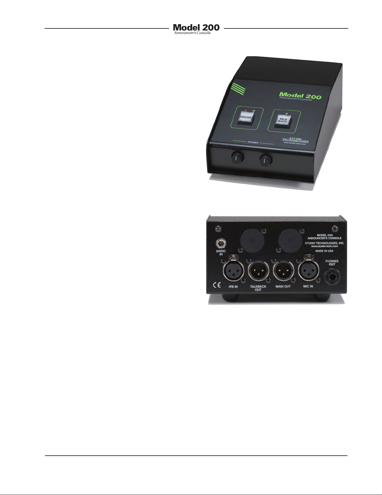
Figure 1. Model 200 front panel
The Model 200 is optimized to directly
interface into the broadcast environments
typically used for events such as football,
baseball, basketball, and motor sports.
Standard connectors are used for the microphone, headphone, talkback, and IFB
signals. This allows setup to be fast and
consistent. A limited number of configuration options are provided. Once selected,
no event-to-event configuration changes
should be required. For ease of use, the
on-air talent is presented with a simple
set of controls and indicators. Whether
it’s mic preamplifier, audio switching,
talkback output, or headphone cue feed,
excellent audio performance is maintained
throughout.
Model 200 User Guide Issue 3, August 2004
Studio Technologies, Inc. Page 5
Figure 2. Model 200 back panel
System Features
Microphone Input and
Configuration
A high-performance microphone preamplifier circuit provides low-noise/low-distortion
amplification over a 20 to 60 dB gain range.
The gain is adjustable in 10 dB steps. The
input is compatible with balanced dynamic
or condenser microphones. The microphone
power source is 48 volts nominal and meets
the worldwide P48 phantom standard.
Page 5

The output of the microphone preamplifier
is used by the main and talkback output
circuits.
One 8-position DIP-type switch array is
used to set the gain of the microphone
preamplifier and the on/off status of the
phantom power. These switches are
accessible via the bottom of the Model
200’s enclosure; the unit does not have
to be disassembled. To prevent access to
the configuration switches a security panel,
included with each unit, is attached to the
bottom of the enclosure.
Main and Talkback Outputs
The Model 200 provides one main and
one talkback output. The main output is
intended to serve as the on-air audio feed.
It is designed as a fully professional interface with high output capability, low distortion, and low noise. It features an output
transformer that is well suited for driving
long broadcast cable runs. The talkback
output is intended to provide production
trucks, control rooms, or support personnel
with a talent-originated cue signal. The talkback output is transformer-coupled with
a +4 dBu nominal signal level. It contains
resistors in series with its output connections, allowing the talkback output from
multiple Model 200 units to be directly
“summed.”
User Controls and Status
Indicators
Two pushbutton switches, three LED indicators, and two rotary controls provide
the user with a clear, easy-to-use interface.
One of the pushbutton switches controls
the status of the main output. This is the
audio output intended for on-air use.
The main output button performs a
“push-to-mute” function that momentarily
mutes the main output. This “cough” function is typically required for on-air applications. Two LEDs display the on/off status
of the main output.
A second pushbutton switch controls the
talkback output. This is the audio output
used to communicate with producers,
directors, or other behind-the-scenes production personnel. The talkback button
provides a “push-to-talk” function. When
active, the talkback function routes the
microphone signal to the talkback output
while muting the main output. A status LED
is associated with the talkback button. Two
rotary controls allow the user to adjust the
level of the headphone output.
IFB Input
A broadcast-standard “wet” (DC with
audio) IFB circuit can be directly connected
to the Model 200’s IFB input. Originated by
sources such as the RTS™ 4000-series IFB
system or IFB interface devices from Studio
Technologies, the connected IFB circuit can
provide DC power to operate the Model 200
as well as two channels of cue audio.
Cue Sources and Headphone
Output
The two audio sources associated with the
IFB input are routed, by way of interface,
level controls, and output circuitry, to the
headphone output. Originating in production trailers, control rooms, or remote locations, these cue sources typically provide
program-with-interrupt audio on one channel and program-only audio on the other.
The Model 200 doesn’t perform any cue
source channel rerouting, summing, or
muting. Channel 1 (pin 2 of the IFB connector) serves as the headphone output’s left
Issue 3, August 2004 Model 200 User Guide
Page 6 Studio Technologies, Inc.
Page 6

channel source. Channel 2 (pin 3 of the
IFB connector) serves as the source for
the headphone’s right channel output.
Some applications may benefit by being
able to connect standard line-level audio
signals to the Model 200. To meet this
need one or two optional line input cards
can be installed in the unit’s back panel.
Each card provides a 3-pin female XLRtype connector and transformer-isolated
+4 dBu nominal input circuit. One card
is assigned to the left headphone output,
the other to the right.
Two rotary controls are provided for user
adjustment of the headphone output
levels. They provide independent volumecontrol adjustment of the left and right
channels. To help minimize the chance of
broadcast cues being missed, both level
controls are configured so that a minimum
headphone output level is maintained.
The headphone output was designed
to meet the needs of contemporary
headphones and headsets. Specifically,
the output circuits act as voltage, rather
than power, drivers. This implementation
provides high output levels with very low
distortion and noise, along with minimal
current consumption. The output circuits
can safely drive stereo or mono loads,
ensuring that all types of headphones,
headsets, and earpieces can be directly
connected.
Audio Quality and Protection
The Model 200’s circuitry has been
carefully designed to provide excellent
audio performance. Pro-audio-quality
components are featured throughout. For
reliability all audio switching is performed
using solid-state devices. In the critical
main output and talkback output audio
paths, “clickless” electronic switches
provide noise-free control. All audio inputs
and outputs make extensive use of protection components. This limits the chance of
damage from ESD and other undesirable,
yet real-world, hazards.
Power Sources
The Model 200 can derive its operating
power from either the IFB input or an external 24 volt DC source. For redundancy,
both power sources can be connected
simultaneously. An internal switch-mode
power supply ensures that all Model 200
features are available, including phantom
power, when powered by either source.
The Model 200 is compatible with IFB
circuits provided by most standard broadcast systems. However, maximum performance can often be obtained by using the
IFB interface devices available from Studio
Technologies. Single-channel and fourchannel units are available, each providing
high-quality audio along with an excellent source of DC power. They’re directly
compatible with most matrix intercom systems, as well as standard line-level audio
signals. Refer to the Studio Technologies
website for details.
Connectors
The Model 200 uses standard connectors throughout. The microphone and IFB
inputs use 3-pin female XLR-type connectors. The main and talkback outputs use
3-pin male XLRs. The headphone output
utilizes a ¼-inch 3-conductor jack. The
external source of 24 volt DC power
is connected by way of a 2.1 x 5.5 mm
“locking” coaxial power jack.
Model 200 User Guide Issue 3, August 2004
Studio Technologies, Inc. Page 7
Page 7

In the world of broadcast audio it’s fair
to say that applications vary widely. To
this end, one or two additional XLR-type
connectors can be easily mounted into
the Model 200’s back panel. Seven
3-position “headers” are located on the
Model 200’s circuit board and provide
technician-access to all input and output
connections. Using a factory-available interface cable kit, these allow a Model 200
to be optimized to meet the exact needs of
specific applications. For example, some
applications may prefer to use a multipin XLR-type connector to interface with
a headset. This could be easily accomplished by adding the appropriate 5-, 6-,
or 7-pin XLR-type connector and making
a few simple connections. Other applications may benefit from having “mult” or
“loop-through” connections, something
easily incorporated into a Model 200. One
or two optional line-input cards, as previously discussed, can also be mounted in
the spare XLR positions.
200-Series Announcer
Installation and
Setup
In this section interconnections will be
made using the input and output connectors located on the Model 200’s back
panel. Microphone input, IFB input, main
output, and talkback output signals are interfaced by way of 3-pin XLR-type connectors. A ¼-inch 3-conductor phone jack is
provided for the headphone output. A 2.1
x 5.5 mm coaxial jack allows connection of
an external 24 volt DC power source.
System Components
Included in the shipping carton are the following: Model 200 Announcer’s Console,
user guide, button label sheet, and 24 volt
DC power supply. For units shipped to
destinations in Japan and North America
the power supply will have a nominal AC
mains input of 120 volts. For all other destinations a power supply compatible with
220/240 volt AC mains will be included.
Console Products
The Model 200 is just one in a series of
announcer console products available
from Studio Technologies. The Model 200
was designed specifically for on-air television sports applications where the performance requirements were well defined.
The unit’s features and operating modes
were selected to provide excellent performance and rapid setup, along with limited
configuration flexibility. For applications
that require additional performance
enhancements the other products in the
200-series should be reviewed. Complete
information is available on the Studio
Technologies website.
Issue 3, August 2004 Model 200 User Guide
Page 8 Studio Technologies, Inc.
Microphone Input
The Model 200 is compatible with balanced dynamic and condenser microphones. Depending on the application,
the microphone may be part of a headset,
or be an independent handheld or standmounted model. The Model 200’s 48 volt
nominal power source will support essentially all phantom-powered microphones.
The quality of the Model 200’s microphone
preamplifier and associated circuitry is
such that special applications may benefit
from using “high-end” microphones. If
selected appropriately, models from manufacturers such as AKG, Beyer, Neumann,
Sennheiser, and Shure will perform very
well in Model 200 applications.
Page 8

Microphone interconnection is made by
way of a 3-pin female XLR-type connector
which is located on the Model 200’s back
panel. The mating connector (male) should
be wired so that pin 2 is signal high (+ or
hot), pin 3 is signal low (– or cold), and pin
1 is shield. It’s possible that an unbalanced
microphone will also work correctly. In this
case, the mating connector (male) should
be wired so that pin 2 is signal high (+ or
hot), and signal common/shield is connected to both pins 1 and 3.
The Model 200 is not compatible with
unbalanced “electret”-type microphones
that require a source of low-voltage DC for
operation. These microphones, sometimes
found in low-cost headsets, are not generally suitable for on-air or other demanding
applications.
As of the writing date of this user guide, the
Sennheiser HMD25 headset is very popular for on-air sports broadcast use. A fine
product, it works very well with the Model
200. Note that adding the suffix “-XQ” to the
headset’s part number (HMD25-XQ) specifies a 3-pin male XLR- type connector for
the dynamic microphone and a ¼-inch 3conductor plug for the stereo headphones.
This configuration is very useful, allowing
the headset to work directly “out of the box”
with the Model 200.
If the writer may digress for a moment to
recount a story… an audio dealer once
shared a secret with me concerning
headsets. He loved selling name-brand
but “lower-end” (less expensive) headsets,
which he did by the veritable “boatload.”
Why? Because they usually broke soon
after going into service! He knew that on a
regular basis he’d receive orders for more of
them. Had these users, from the beginning,
purchased only premium-quality headsets,
their total cost of ownership would have
been much less. Enough said…
Headphone Output
The Model 200’s headphone output is compatible with stereo or mono headphones,
headsets, or earpieces. Connecting devices
with a nominal impedance of 100 ohms or
greater is preferred. This shouldn’t prove to
be an issue as essentially all contemporary
devices will meet this condition.
Devices are connected to the headphone
output by way of a ¼-inch 3-conductor
phone jack which is located on the Model
200’s back panel. As is standard for stereo
headphones, the left output is connected
to the “tip” lead of the ¼-inch headphone
jack. The right output is connected to the
“ring” lead of the jack. Common for both
outputs is connected to the “sleeve” lead.
Devices with ¼-inch 2-conductor “mono”
plugs can also be used with the Model
200’s headphone output. In this arrangement only the tip lead (left channel) will
be active. The 2-conductor plug will physically connect (“short”) the ring lead (right
channel) to the sleeve lead (common).
Technically this won’t damage the circuitry
associated with the right-channel headphone output. (51 ohm protection resistors
are electrically in series with the headphone
output circuits.) However energy will be
wasted if an audio signal coming out of
the right channel goes into a “dead short.”
There are several ways of limiting the
chance that this condition will occur. The
first way is to disconnect or “un-route”
any audio source going to channel 2 of
the connected IFB circuit. Channel 2 audio
is found on pin 3 of the IFB input XLR-type
connector. The second way is pretty obvious—keep the right channel level control
Model 200 User Guide Issue 3, August 2004
Studio Technologies, Inc. Page 9
Page 9

in its fully counterclockwise position. A
third way is preferred, but unfortunately
might prove to be impractical out in the
field. It would mandate the use of ¼-inch
3-conductor plugs on all devices, stereo or
monaural, that are to be connected. Stereo
headphones or headsets would connect
in the usual way: left channel on tip, right
channel on ring, and common on sleeve.
But monaural devices would connect only
to the tip and sleeve leads; the ring lead
would remain unconnected. This would
ensure that the Model 200’s right-channel
headphone output would never be shorted.
Main Output
The main output is intended to be the
“on-air” signal that connects to the input of
an audio console. The output is transformer
balanced with a nominal signal level of
–2 dBu. The actual level will depend on the
gain setting of the microphone preamplifier, sensitivity of the microphone, and how
loudly the talent speaks into the microphone. The transformer used in the main
output is intended for professional broadcast applications. It has a low source impedance and can drive lengthy cable runs
with no difficulty. It is capable of driving 600
ohm loads but performs best with loads of
2 k ohms or greater. (This should not prove
to be an issue as virtually all contemporary
audio equipment has a relatively high input
impedance.) As the secondary winding of
the output transformer connects directly to
the main output connector, care should be
taken so that DC voltage is never present
on the interconnecting cable.
The main output is interfaced by means
of a 3-pin male XLR-type connector
located on the Model 200’s back panel. The
interconnecting cable’s mating connector
(female) should be wired so that signal high
(+ or hot) is on pin 2 and signal low (– or
cold) is on pin 3. The cable’s shield can
be connected to pin 1, but it will have no
function. To limit the chance of grounding
interaction between the Model 200 and
connected equipment, pin 1 on the main
output’s connector is isolated from any
point in the Model 200. The fact that pin 1
“floats” will minimize the chance of hums,
noises, or buzzes being present on the
equipment connected to the main output.
Talkback Output
The talkback output is intended for
connection to control rooms, production
trailers, or other locations where talentoriginated voice cues are required. The
talkback output is transformer-balanced
with a nominal level of +4 dBu. The actual
level will depend upon the output level
of the connected microphone and the
amount of gain selected for the microphone preamplifier.
For protection against accidental connection to cables that have DC power present,
the talkback output is capacitor coupled.
In series with the talkback output leads
are 300 ohm resistors, making the effective output impedance approximately
600 ohms. These resistors allow talkback
outputs on multiple Model 200 units to
be connected together, creating a passive
summing network.
The talkback output is connected by way
of a 3-pin male XLR-type connector which
is located on the Model 200’s back panel.
A mating connector (female) should be
prepared so that signal high (+ or hot) is
expected on pin 2. Signal low (– or cold)
should be expected on pin 3. The cable’s
shield can be connected to pin 1. But, like
the main output, to minimize the chance
Issue 3, August 2004 Model 200 User Guide
Page 10 Studio Technologies, Inc.
Page 10

that ground problems will arise, pin 1 of
the talkback output connector is isolated
from any point in the Model 200. By making pin 1 “float,” an often-feared “ground
loop” problem shouldn’t arise.
The talkback output is intended to drive
lengthy cable runs that are frequently part
of a remote broadcast application. While
the output circuitry is not intended to be
“on-air” quality, overall audio performance
should be very good. Devices connected
to the talkback output can range from
amplified loudspeakers, analog inputs
on intercom systems, and input channels
associated with audio consoles. Connecting the talkback output to devices that
allows easy control of the signal level
can be helpful. For example, connecting
to a spare input module on an audio
console provides the flexibility to add
“gain or attenuate as required. A talkbackassociated output connection on the
audio console can then connect to the
final destination(s).
As previously mentioned, the talkback
outputs on multiple Model 200 units can
be directly connected together. Using
a simple “Y” or “W” cable, this passive
summing (adding together) of talkback
signals allows one audio cable to serve
as a master talkback path. A side effect
from using this passive summing technique is that signal attenuation will occur.
The audio quality won’t suffer, but this
passive mixing method does create an
audio “pad.” If two talkback outputs are
connected together, a signal attenuation
of 6 dB can be expected. Connecting
three talkback outputs together will result
in 9.5 dB of attenuation. And four talkback
outputs “multed” together will lead to
12 dB of attenuation. In most cases this
attenuation won’t pose a problem.
Typically a device that receives the
talkback signal, such as an amplified
loudspeaker, will have adjustable input
sensitivity.
IFB Input
The Model 200’s IFB input is designed
to directly connect with “wet” (DC-biased)
IFB circuits. These circuits provide DC
power and one or two channels of audio
over a standard 3-conductor microphonestyle cable. Typically, the IFB circuit’s interface connector is a 3-pin male XLR-type
wired so that common is on pin 1, DC with
channel 1 audio is on pin 2, and channel
2 audio is on pin 3. Some IFB circuits may
only have one audio channel. In this case,
audio will generally be on pin 3 with pin 2
providing only DC power.
The power supplied by an IFB circuit,
normally in the range of 28 to 32 volts
DC, is usually sufficient to operate the
Model 200’s circuitry. The acceptable
input range is 24 to 32 volts, with a
required current of 95 milliamperes. Note
that the specified input voltage is given
when measured directly at the Model
200’s IFB input connector, not at the
source of the IFB circuit. The one or
two audio signals provided by the IFB
circuit will serve as the audio source(s)
for the headphone outputs. Audio that
arrives on pin 2 of the IFB input connector is used for the left-channel headphone
output. Audio on pin 3 is used for the
right-channel output. The Model 200’s
IFB input has a nominal audio level of –10
dBu, matching that of typical IFB circuits.
In North American field and in-studio
broadcast applications it is common
to find RTS 4000-series IFB equipment
being used to provide the IFB circuits.
Model 200 User Guide Issue 3, August 2004
Studio Technologies, Inc. Page 11
Page 11

The Model 200 can be directly connected
to, and function correctly with, one of these
circuits. For reliable operation, especially
when using lengthy cable runs, it’s strongly
recommended that no other device be
connected to a 4000-series IFB circuit that
is specified for connection to a Model 200.
This requirement is due to the currentlimited DC source that is supplied by the
4010 IFB Controller.
With 4000-series IFB circuits channel 1
(XLR pin 2) provides program audio that
is “interrupted” with cue signals. This
channel is sometimes referred to as “program-with-interrupt.” It’s important to note
that the program audio source fully mutes
whenever directors or producers are communicating with on-air talent. Channel 2
(XLR pin 3) of the IFB circuit provides a
“program-only” audio feed. It is never interrupted with cue signals.
While the Model 200’s IFB input was
designed for connection to a “wet” IFB
circuit, it’s also possible to connect linelevel audio sources. Please refer to the
Technical Notes section of this user guide
for details.
been terminated with a Switchcraft®
S760K coaxial power plug. This “locking” type of plug correctly mates with the
Model 200’s DC input jack. The locking
feature is important, allowing the external
power supply to be securely attached to
the Model 200.
As previously discussed in this user
guide, an IFB circuit connected to the
IFB input can serve as the Model 200’s
power source. Alternately, an external 24
volt source can be connected. For redundancy, both the IFB circuit and the external source can be connected at the same
time. If one or the other becomes inoperative, the remaining source will provide all
Model 200 power.
Note that if both an IFB circuit and an
external 24 volt DC source are connected,
power will be drawn only from the external source. This minimizes the chance
that lengthy cable runs or other IFB circuit
issues will impact Model 200 operation.
Whatever device is providing power, audio
signals from the IFB circuit will continue to
serve as the audio source(s) for the headphone output.
External Power Input
An external source of 24 volt DC power
can be connected to the Model 200 by way
of a 2.1 x 5.5 mm coaxial power jack which
is located on the unit’s back panel. The
center pin of the jack is the positive (+)
connection. While the requirement for the
external source is nominally 24 volts, correct operation will take place over a 20 to
30 volt range. The Model 200 requires 50
milliamperes maximum for correct operation. Included with each Model 200 is a
24 volt DC external power supply. The
power supply’s DC output cable has
Issue 3, August 2004 Model 200 User Guide
Page 12 Studio Technologies, Inc.
Pushbutton Labeling
The two pushbutton switches used in
the Model 200 were selected for several
reasons. Foremost was the fact that they
were highly reliable, using gold-plated
contacts for long life in less-than-ideal
environments. A second reason was that
applying customized labels to the button
caps would be very simple. The labels,
text printed on clear material, are placed
under the clear caps that are on the top
of the buttons. From the factory the left
button is labeled COUGH and the right
button is labeled TALKBACK. This was
Page 12

selected to be appropriate for many on-air
applications in English-speaking locations.
But it’s expected that these may need to
be changed to meet the needs of specific
applications.
As a “head start” for some applications,
included in the shipping carton is a clear
sheet with a number of commonly used
button designations printed on it. These
were created at the factory using a standard personal computer graphics program
and laser printed onto 3M CG3300 transparency film. The desired button labels
can be cut out with a pair of scissors, following the printed guide lines that indicate
the required size.
The clear lens on top of each button cap
can be removed with a fingernail or small
screwdriver. Be certain not to scratch the
button if a screwdriver or other small tool
is used. The clear label can then be
removed and replaced. The button cap
is then snapped back into the top of the
button housing using finger-pressure
only. No tool is required to replace the
button cap.
Configuration
For correct Model 200 operation, two
operating parameters must be configured:
microphone preamplifier gain and phantom power on/off. An 8-position DIP-type
switch assembly is used to set the desired
configuration. Refer to Figure 3 for a detailed view of the configuration switches.
These switches are accessible through an
opening in the bottom of the Model 200’s
enclosure. The enclosure does not have
to be disassembled to gain access to the
switches.
If you need to make your own labels the
process is quite simple. Use a personal
computer to create the desired text. The
finished label size should be 0.625-inches
(15.8 mm) square. The completed artwork
can then be printed on transparency
film sheets using a laser or inkjet printer.
These sheets are readily available from
most office supply stores. A pair of scissors or an X-ACTO® knife will complete
the task.
Figure 3. Bottom view of Model 200 showing
configuration switches
Model 200 User Guide Issue 3, August 2004
Studio Technologies, Inc. Page 13
Page 13

To prevent unauthorized personnel from
changing configuration settings, a security
plate is attached to the bottom of the Model
200’s enclosure. For convenience, attached
to the security plate is a configuration settings label. It provides a summary of the
configurable parameters and related information. Refer to Appendix A for a representative view of the label. The security plate
is held in place by means of four rubber
bumpers (“feet”) that have built-in screws.
Using your fingers, remove the four bumpers so that the plate becomes loose.
Selecting the correct amount of gain for an
application might take a little experimentation. The goal is to bring the mic’s signal up
to line level, nominally –2 dBu for the Model
200’s main output. Operating at this signal level will help to ensure the delivery of
“clean” audio to the connected device.
The output of the Model 200’s microphone
preamplifier is used by both the main and
talkback outputs. So creating a nice “hot”
signal will help maintain audio quality,
specifically the signal-to-noise ratio, when
driving the often-lengthy cable runs.
Microphone Preamplifier Gain
Switch positions 1-5 are used to select the
gain of the microphone preamplifier. The
choices are 20, 30, 40, 50, and 60 dB. Only
one switch should be enabled at a time.
There’s no problem changing the gain setting while the unit is operating. Audio clicks
or pops might occur during gain transitions,
but this shouldn’t be a major issue as long
as associated monitor loudspeakers are
temporarily attenuated or muted.
Unfortunately, there’s no “perfect” gain
setting that this guide can recommend.
The two issues that impact the setting are
output sensitivity of the connected microphone and the acoustical output level of
the microphone’s user. With some headset microphones, such as the Sennheiser
HMD25, selecting an initial setting of 40 dB
is be appropriate. Users who speak loudly
might need to have the gain reduced to 30
dB. Quiet users might need 50 dB of gain.
It’s expected that the 20 and 60 dB gain
settings will not often be used. But there are
always exceptions and that’s why they were
included. It’s possible that with a very “hot”
microphone, such as a phantom-powered
condenser-type, 20 dB of gain could be
correct. It’s also possible that a microphone
with a very low-level output, such as a
ribbon-type, would need 60 dB of gain.
But in general, the 30, 40, and 50 dB gain
settings will serve most applications.
Note that if no gain switch is set to its active
(on) position the preamplifier will operate at
unity (0 dB) gain. In this mode the preamplifier remains stable, but is intended for use
Figure 4. Microphone preamplifier gain switch
settings
only during factory testing. The only exception would be a special application where
a line-level signal was connected to the
Issue 3, August 2004 Model 200 User Guide
Page 14 Studio Technologies, Inc.
Page 14

microphone input. But with a microphone
connected as the input source one should
never use the 0 dB setting. The issue is
that with no gain added to the microphone
input signal, the relative noise floor on the
main and talkback outputs will be much
too high. These outputs are designed for
handling line-level signals, expecting to
receive the output of the microphone
preamplifier. In conclusion, the 0 dB gain
setting doesn’t highlight a problem, but
simply reflects the unit’s gain structure.
Phantom Power On/Off
Position 8 of the switch assembly controls
the on/off status of the 48 volt phantom
power supply. As expected, placing the
switch to the on position applies phantom
power to the microphone input. By phantom power’s very nature it could be left
applied to the microphone input at all
times. But generally people prefer to
turn it off unless required for a specific
microphone.
Operation
At this point the desired input, output, and
power connections should have been
made. The button labels may have been
revised. Finally, the configuration switches
should have been set. Normal operation
of the Model 200 can now begin. The unit
will begin functioning as soon as a power
source (either the IFB circuit, external 24 volt
DC power source, or both) is connected. It’s
important to highlight the fact that the Model
200 is an active device. Audio signals will
not be present on the main output if correct
power has not been supplied! The microphone does not passively “cut through” to
the main output connector.
Upon power up, only the green LED associated with the main output button, factory
labeled as COUGH, will be lit. The user
is now presented with two buttons, three
LEDs, and two rotary controls. These are
simple to operate and understand, as will
be described in the following paragraphs.
Pushbutton Switches and
Status LEDs
Two pushbutton switches are used to
control the main and talkback outputs.
The button on the left, factory labeled as
Figure 5. Phantom power switch settings
Conclusion
Once the switches have been set to the
desired configuration, the security plate
should be reattached. The four rubber
bumpers should be hand-tightened only.
No tools should be used.
Model 200 User Guide Issue 3, August 2004
Studio Technologies, Inc. Page 15
COUGH, provides a push-to-mute function
for the main output. The function is momentary, the output mutes only when the button
is pressed and held. Two LED indicators
are located directly above this button. The
green LED is lit whenever the main output
is active. This could be considered to be an
“on-air” or mic active indicator, or at least
serve as a “careful what you say” warning!
The red LED, located to the left of the green
LED, is lit whenever the main output is not
active.
Page 15

The button on the right, factory labeled
as TALKBACK, provides a push-to-talkback function. The function is momentary,
activating the talkback output only when
the button is pressed and held. One LED
indicator is located directly above this
button. Green in color, it lights whenever
the talkback output is active. Also, whenever the talkback output is active the main
output is muted. The LEDs associated with
the main output will light accordingly.
If both buttons are pressed at the same
time, the main output is muted and the
talkback output is active.
Headphone Output Level
Controls
Two rotary level controls are located on
the Model 200’s front panel and are associated with the headphone outputs. The
control on the left side is used to set the
level of the left headphone output. The
control on the right side is used to set
the level of the right headphone output.
In typical sports broadcasting applications, the left headphone output will supply program audio that is interrupted with
cue signals. The right headphone output
will supply an uninterrupted source of
program audio.
By design, the headphone level controls
will not turn their respective outputs to
a fully muted condition. When a control
is set to its fully counterclockwise position,
the output will be 40 dB below its maximum level. This setting ensures that
talent will never be fully “isolated” from
potentially important cue signals. Some
signal will always be presented to the
headphone outputs.
Each level control has a mechanical step
(detent) that is located at the halfway
(50%) position of its rotation range. This is
intended to serve as an aid to Model 200
users. In an ideal installation, setting the
controls to their detent position will result
in a comfortable headphone output level.
The user can then move the level control as
desired to get more or less level as conditions change. But the detent position will
always remain as a useful reference point.
To achieve this condition the audio level
on the connected IFB circuit would have to
be adjusted as required. This is somewhat
counter to the usual mentality of just providing the user with whatever level comes up
by default. Spending a few extra minutes
“trimming” the audio levels can result in
much happier, and more productive, talent.
Technical Notes
Grounding and Shielding
As previously discussed in this user guide,
the pin 1 connections on both the main and
talkback outputs’ 3-pin male XLR-type connectors are “floating,” i.e., not connected to
anything within the Model 200’s enclosure.
Some audio experts might take offense to
this, grousing that this should have been
left to the user or installer to be connected
or disconnect as desired. However, repeated field testing found that floating pin
1 on the outputs was the key to maintaining quiet audio. From Fenway Park, to the
Orange Bowl, and then northwest to Husker
Stadium, lifting pin 1 did the trick.
A simple solution is available if an application does require that a ground be available
on the main and talkback outputs’ interconnecting cable. All Model 200 XLR-type
connectors have a ground connection that
is made to the interfacing connector’s metal
“shell.” And most XLR-type connectors
Issue 3, August 2004 Model 200 User Guide
Page 16 Studio Technologies, Inc.
Page 16

have a pin or connection point available to
access its metal shell. By adding a jumper
wire from the mating connector’s shell
terminal to its pin 1 and cable shield, the
common connection typically found on
audio interconnections is created.
IFB Channel Crosstalk
By the very nature of its design, standard
“wet” IFB circuits are prone to exhibit
crosstalk between the two audio channels.
This occurs because the audio path is
unbalanced (“single-ended”) and typically
transported on a single shielded twistedpair audio cable. The primary cause of
the crosstalk is the capacitance between
the wires in the cable pair. The greater the
capacitance, due to cable type and length,
the more crosstalk there will be. It’s not
surprising to find in sports broadcasting
venues that audio from one channel in an
IFB circuit can be heard “bleeding” into
the other channel. Is this generally an issue? No, as each channel in an IFB circuit
generally carries related audio content.
For example, on-air talent hearing in their
left ear a small amount of program audio
from channel 2 while an interrupt from
channel 1 is active, typically wouldn’t be
a problem.
There are several ways of reducing IFB
channel crosstalk. Probably the easiest way is to use cable pairs that are not
twisted. Twisted pairs are great for differential (balanced) signals, but not so
great for unbalanced transmission. This
is generally because the more twists in
a pair the greater the cable capacitance.
In a stadium or arena setting, choosing
standard “telco” pairs may actually work
better than “high-performance” audio or
data cable!
Another option is to use two cable pairs
for each IFB circuit. If the pairs are not
shielded the wiring is simple. Common
would be connected to one side of each
pair, and then signal from each channel
would connect to the other side of the
pairs. If the pairs also contain shields
the wiring could be done somewhat differently. One option is to connect common
to both cable shields, IFB channel 1
(DC with audio) to one full pair, and IFB
channel 2 to the second full pair. A better
option might be to have common connect
to both shields and one side of the pair
that serves IFB channel 2.
Other options are available if an application demands low crosstalk. If resources
in the broadcast or production facility allow one method would be to run the
IFB circuits “dry” (no DC) and differential
(balanced). This would gain the benefits
of differential transmission, including minimizing the crosstalk. If optional line input
cards have been installed in the Model
200, the balanced line-level signals can be
directly connected. However, if it’s desired
to connect cue sources to the Model 200
using an IFB-type circuit, the line-level
audio signals will need to be “wetted up”
into standard IFB circuits. This is easily
accomplished using one of several highperformance IFB interface units from
Studio Technologies. For further information please refer to the Studio Technologies website.
IFB Audio Levels
The Model 200 is designed to operate
best with IFB audio levels that are nominally –10 dBu. This is the nominal level
of most IFB systems, such as the RTS
4000-series. But actually having the correct level present on an IFB circuit is often
Model 200 User Guide Issue 3, August 2004
Studio Technologies, Inc. Page 17
Page 17

a “hit-or-miss” proposition. During field
testing of prototype announcer’s consoles,
Studio Technologies’ personnel found
that a wide range of nominal audio levels
were present on “real-world” IFB circuits.
Many were fine, being reasonably close
to –10 dBu. But some were much too low,
while others much too “hot.” We observed
one unfortunate baseball “color” commentator being sent interrupt audio signals
so “hot” relative to program audio as to
almost make his ears bleed! This situation
should not have been allowed to happen.
In defense of field technical personnel,
measuring the audio level of an IFB circuit
hasn’t traditionally been an easy proposition. But that situation has now changed.
After experiencing this condition in the
“field,” Studio Technologies’ engineers
were motivated to design the Model 72
Level Meter/Interface. This compact
device plugs directly into IFB and intercom
circuits and provides two useful functions:
level meters and “dry” audio outputs.
Two 5-segment LED meters allow direct
observation of the audio signal levels
present on IFB or intercom circuits. The
display range is optimized for the signal
levels found on these circuits, rather than
traditional “VU” scaling. The Model 72 also
provides two transformer-coupled “dry”
audio outputs, one for each IFB or intercom channel. These outputs are useful for
a variety of production and testing applications. For example, the outputs can serve
as the interface between a traditional “wet”
IFB system and a wireless in-ear monitor
system. The outputs can also be connected to a monitor panel, allowing visual and
aural monitoring of the IFB audio signals.
In conclusion, we’re sorry for this shameless promotion of the Model 72 Level
Meter/Interface! But necessity was
definitely the “mother” when it came to
the unit’s invention. Working “in the field”
without such a device, we felt “blind” when
connecting to IFB circuits. That no longer
has to be the case and we think that you’ll
finding owning one a very worthwhile
investment. For further information please
refer to the Studio Technologies website.
Phantom Power
The Model 200 provides a 48 volt nominal source of “phantom power” to support condenser-type microphones. It’s
designed to meet the P48 requirements as
specified in the IEC 61938 standard. The
circuitry is very simple: two 6.81 k ohm
resistors provide a path from a 48 volt
source to pins 2 and 3 of the microphone
input connector. The resistors and the
power source work together to provide 48
±4 volts, up to a maximum current of 10
milliamperes.
External Power Sources
As has been previously discussed, an
external source of 24 volt DC can be used
to power the Model 200. While developing the 200-series of announcer console
products, an interesting phenomenon was
discovered regarding acceptable sources.
To meet worldwide requirements, using
a compact switch-mode “universal input”
power supply seemed to be an excellent
solution. Supplying one of these with each
Model 200 would have allowed operation
anywhere in the world. Whether connecting to 100 volts, 60 Hz in Japan or 240
volts, 50 Hz in Australia all would be well.
Unfortunately, things did not work out as
planned! It turned out that all of the compact switch-mode power supplies that
were tested induced a great deal of noise
into their DC output. This noise, especially
Issue 3, August 2004 Model 200 User Guide
Page 18 Studio Technologies, Inc.
Page 18

noticeable in the negative lead of their DC
output, fed right into the common lead of
the IFB circuit. From what could be determined, noise current would travel from
the power supply, through IFB input pin 1,
and on to the IFB circuit source’s ground
connection. Making the problem more
insidious was the fact that only when the
IFB circuit’s interconnecting cable was
sufficiently long did the problem become
noticeable. In the “lab” where 10-foot long
test cables were used, the audio from the
IFB circuit was extremely quiet. But testing
with 500 or 1000 feet of interconnecting
cable resulted in an annoying “buzz” on
the IFB audio channels.
Many hours were spent trying to eliminate
this problem. But, unfortunately, no solution was found. It was a humbling experience that only a few visits to the local
tavern made us feel better about.
The solution turned out to be very simple,
but not without other ramifications. By
changing to a low-cost transformer-based
(“linear”) 24 volt DC power supply the
problem disappeared. With no highfrequency switching noise to get into
the IFB circuit, everything worked fine.
But a new problem arose when it came
to finding an external linear power supply for Model 200 users worldwide. For
locations that are served by 100 or 120
volts, 60 Hz a 24 volt DC linear “wall-wart”
power supply was readily available. This
is the power supply that is provided with
the Model 200 when it is shipped to North
America or Japan. But as of this writing, no “perfect” 24 volt DC linear power
source has been located that would serve
220/240 volts, 50 Hz applications. So a
compromise had to be made. For these
applications a small universal input switchmode power supply is included with each
Model 200. It’s far from an ideal solution,
leading to noise on the IFB audio channels when long cable runs are present.
But at least users will have an “emergency” power source if nothing else is
available.
In conclusion, users where the AC mains
power is 220/240 volts should consider
locating an alternate 24 volt DC power
source. Several options are available that
could make the task simple. It’s expected
that a more sophisticated “medical-grade”
switch-mode power supply will have much
better control of induced noise. It’s highly
likely that using one of these supplies will
provide good results. As the Model 200’s
current requirement is only 50 milliamperes, a typical medical-grade power supply should be able to power multiple units.
Another solution would be to obtain two
of the more commonly available 12 volt
DC linear power supplies, connecting their
outputs in “series” to create a 24 volt DC
source. While not a glamorous solution,
it is technically correct and should prove
cost effective. If this arrangement is implemented remember that the center pin of
the 2.1 x 5.5 mm coaxial jack is used for
the positive (+) connection.
Symptoms of Insufficient
Power
A core part of the Model 200’s internal circuitry is a switch-mode power supply that
produces +48 volts, +12 volts, and –12
volts. This power supply circuit works very
well as long as it is “fed” with sufficient input voltage and current. “Sufficient” is defined as a minimum of 24 volts on the IFB
input and 20 volts on the external 24 volt
DC input. The IFB input must be capable
of supplying 95 milliamperes of current
over its entire voltage range. The external
Model 200 User Guide Issue 3, August 2004
Studio Technologies, Inc. Page 19
Page 19

source must provide 50 milliamperes at
24 volts DC.
It’s worth discussing what will happen if
either power source falls below its specified
minimum. Typically, if the Model 200 is being powered by an external power source,
apparently normal operation will continue
until the input falls to the 18-20 volt range.
The Model 200’s internal power supply will
have reduced stability until its low-voltage
shutdown circuit halts its operation. Note
that as the input voltage moves down from
24 volts the input current will rise proportionately to make up for the loss of power.
If an IFB circuit is powering the Model 200,
maintaining the required voltage and current is more critical. Should the voltage or
current fall below the specified minimum,
the Model 200’s power supply circuit will
again become unstable. This will become
an issue as noise will be induced into the
IFB circuit’s audio signals. The reason
is simple: an IFB circuit “multiplexes”
3-conductors so that they carry both power
and audio signals. If sufficient amounts of
voltage and current are presented to the
IFB input, the Model 200’s power supply
draws a nice and steady amount of energy.
This will not disturb the analog signals
on pin 1 (common for DC and audio) and
pin 2 (DC and channel 1 audio). But if the
Model 200’s power supply is not presented
with sufficient energy it will try to draw what
it needs from the IFB circuit, becoming
unstable in the process. The IFB circuit’s
audio signals will be corrupted by the
power supply’s attempt to draw enough
power. Instead of nice clean audio there
will be squeaks, squeals, and some awfully
funky noises added. Again, in a low-voltage
or low-current situation, no damage will be
done to the Model 200’s circuitry but correct operation will not be possible.
In most cases maintaining the IFB circuit’s
required voltage and current shouldn’t
be a problem. But issues may arise due
to malfunctioning IFB sources or poor
interconnect cabling. Typically, excessive
cable length won’t be the cause of a problem. Generally, problems will be caused
by broken or damaged connector pins,
dirty patch points, or damaged (partially
open) cable conductors. Measuring the IFB
circuit’s voltage and current draw directly
at the Model 200’s IFB input connector will
quickly identify if there’s a power issue.
And now for another shameless “plug” for
other Studio Technologies products: Frankly, most devices that supply IFB circuits
for broadcast applications use outdated
technology that provides mediocre performance. That’s why Studio Technologies’
developed high-performance IFB interface
units. These products do an excellent job
of providing power and audio to connected
devices such as the Model 200. However,
unlike other products, the power supplied
by these units’ IFB circuits maintain their
output voltage all the way to their full rated
current. The result is being able to power
more devices over longer cable runs. In
addition, the audio quality of these units
is superior. For further information please
refer to the Studio Technologies website.
LED Colors
As previously described, two LED indicators are associated with the main output
and are located directly above the main
output pushbutton switch. The red LED,
located on the left, is lit whenever the main
output is muted. The green LED, located
on the right, is lit whenever the main output
is active. The thought process behind the
color choices was that red would relate to
the main output being muted (“stop”) while
Issue 3, August 2004 Model 200 User Guide
Page 20 Studio Technologies, Inc.
Page 20

green would relate to the main output being active (“go”). It’s possible that these
color choices may not meet the needs of
all users and applications. For example,
it’s reported that one European broadcaster typically uses the colors in the opposite
fashion. Their choice is to have the red
LED lit whenever the main output is active,
warning the talent that they are “on-air.”
The green LED is lit whenever the main
output is muted, indicating to the talent
that it’s “safe” to say whatever they wish,
about whomever they wish to say it about!
For consistency, the LED associated with
the talkback button was selected to be
green. This lights whenever talkback is
active. It’s possible that some applications
may benefit from revising this LED color,
too. While red is certainly one possible
choice, other colors are also a possibility
including amber, orange, or blue—these
days there are lots of choices available.
The only limitation is the amount of current
available to light each LED. Using series
resistors of no less than 560 ohms will
ensure correct Model 200 operation.
A qualified technician can easily revise
the LED colors to meet an application’s
exact needs. The process would begin
by disassembling the Model 200’s enclosure and detaching the pushbutton/LED
printed circuit board assembly. The LEDs
would then be unsoldered, removed, and
reinstalled (or replaced) in the desired
locations. To control the LED current and
set the brightness, a resistor is electrically
in series with each LED. An 820 ohm,
¼-watt resistor is associated with the red
LED while a 560 ohm, ¼-watt resistor is
associated with each green LED. These
resistors would also have to be unsoldered, removed, and reinstalled. Then the
unit would be reassembled and tested
to confirm that the changes function as
desired. For additional information about
changing the LED colors, please contact
Studio Technologies’ technical support.
Travel Case
For portable applications it may be desirable to store and transport each Model
200 in a protective case. After much travel
with prototype announcer console units,
Studio Technologies’ personnel learned
to appreciate the Pelican Model 1450
case. Purchased with the foam interior
option, it does an excellent job of holding one Model 200, associated 24 volt DC
power supply, and related documentation.
Some applications may benefit from selecting a larger case that would also hold
a related headset, cables, etc. A larger
case could also be selected that would
hold multiple Model 200 units. Pelican
sells their products through a dealer network, many of which can be located via a
web search.
Connecting Line-Level Inputs
The Model 200’s IFB input was designed
to work with “wet” broadcast IFB circuits.
However, there may be applications where
it would be helpful to be able to connect
standard line-level audio sources. If it’s
anticipated that line-level audio sources
will frequently need to be connected to
the Model 200, one or two line input cards
can be installed. These cards, available
from Studio Technologies and purchased
separately (part number 31084), are
mounted into spare connector locations
that are provided on the Model 200’s back
panel. The line input card contains passive
circuitry, including a 3-pin female XLRtype connector and a 10 k ohm to 10 k
ohm isolation transformer. Once installed,
Model 200 User Guide Issue 3, August 2004
Studio Technologies, Inc. Page 21
Page 21

balanced or unbalanced line-level audio
sources can be directly connected. Note
that in cases where only line-level signals,
rather than an IFB circuit, is connected to
the Model 200 an external source of 24
volt DC power is required. This shouldn’t
pose a problem as a 24 volt DC power
supply is included with each Model 200.
Each line input card kit contains a printed
circuit board assembly, an interconnecting cable, and hardware. To install the kit
is very simple. The XLR-type connector is
mounted into one of the spare connector
locations on the Model 200’s back panel.
This secures the connector and associated printed circuit board to the enclosure. The interconnecting cable is then
used to link the card and the Model 200’s
main printed circuit board assembly. One
end of the cable is plugged into the line
input card’s 3-position “header” that is
labeled OUT. The other end of the cable
is plugged into the desired 3-position
header located on the main printed circuit
board. The header associated with the left
channel of the headphone output is labeled P11. (This is the same channel that
IFB channel 1 is routed to.) The header
associated with the right channel of the
headphones is labeled P10. (This is same
channel as IFB channel 2.) Note that the
unused header remaining on the line input
card has its pins “multed” with the leads
on the 3-pin female XLR-type connector. It
is provided for other applications that may
need it. Additional installation details are
provided in the next section of the user
guide. Included is a recommended connector labeling method that is appropriate
when line input cards are installed.
For balanced audio sources the mating
connector (3-pin male XLR-type) should
be wired so that signal high (+ or hot)
is connected to pin 2, signal low (– or
cold) is connected to pin 3, and shield is
connected to pin 1. Unbalanced sources
should be wired so that signal high is on
pin 2, and signal low/shield is connected
to both pins 1 and 3. If this results in hum
on the input, trying connecting signal high
to pin 2, signal low/shield to pin 3, and pin
1 left unterminated (“floating”).
Several things are worth mentioning when
it comes time to actually use a line input
card. The input is transformer coupled
with a nominal input impedance of
10 k ohms. Capacitors in series with the
transformer’s primary provide protection
against accidental connection of a cable
that has DC voltage present on it. The
nominal input level is +4 dBu but should
work correctly with signal levels down
to nominal –10 dBu. So that the rotary
level controls provide a more comfortable
range of operation during actual use, reducing the level of a “hot” input signal by
3 to 6 dB is preferred, versus having a full
+4 dBu nominal level.
Note that if one or two line input cards
are installed in a Model 200, both “dry”
line-level audio signals and a “wet” IFB
circuit can be connected at the same
time. Nothing untoward will happen to the
Model 200 or related connections. The left
channel of the headphone output will have
a mix of left-channel line-level audio and
IFB channel 1 audio. The right channel
will have a mix of right-channel line-level
audio and IFB channel 2 audio. There is
no reason why this situation can’t be used
to meet the needs of special applications.
In “emergency” situations it’s possible to
connect line-level audio signals directly
to the Model 200’s IFB input connector.
This can be successfully done as long as
Issue 3, August 2004 Model 200 User Guide
Page 22 Studio Technologies, Inc.
Page 22

several limitations are taken into account.
The first limitation is that the 10 k ohm
input circuit presents an unbalanced load
to the source. In most cases this shouldn’t
pose a problem. If a balanced interconnection scheme must be maintained
in-line isolation transformers can be used.
A second limitation is that the audio level
presented must not exceed 0 dBu or signal “clipping” may occur. Prepare a 3-pin
male XLR-type connector so that the linelevel audio source designated as channel
1 (left headphone output) is connected
with signal high on pin 2 and low/shield on
pin 1. The audio source designated as
channel 2 (right headphone output)
should be connected with signal high
on pin 3 and low/shield on pin 1. With
this connection scheme the nominal input
level is –10 dBu, the same as with an IFB
circuit. As expected, powering the Model
200 requires an external source of 24 volt
DC to be connected.
Additional Connectors
Two spare connector locations are provided on the Model 200’s back panel. From
the factory they contain blank plates that
can be readily removed and replaced with
a variety of XLR-type connectors. These
spare connector locations are specifically included so that a Model 200 can
be customized to meet the many specific
needs that arise in broadcast and related
audio applications. Expected uses for
these locations include adding a 5-, 6-, or
7-pin XLR-type connector to allow direct
connection of a broadcast headset. Other
uses include creating “loop through” or
“mult” functions for the talkback output or
IFB input connections. In addition, Studio
Technologies offers an optional line input
card that mounts directly in a spare
connector location. This was previously
described in this user guide.
The spare connector locations are
compatible with the Neutrik DL-series
of connectors. For flexibility, versions are
available that provide from three to seven
contacts. For example, a compatible 3-pin
female connector would be Neutrik part
number NC3FD-L-1. To support headsets
the NC6FDS-L-1 is often used. This is a
6-pin female connector with the unique
Switchcraft 6-pin arrangement. The hardware that secures the blank plates to the
Model 200’s back panel is also intended
to secure the replacement connectors.
If connectors are added to the Model
200’s spare connector locations adding
labels to those connectors can be helpful.
For a great look it is recommended that
Brother® P-Touch ¼-inch (6 mm) labels
be created. Tape material that prints white
text on a black background works out
well for the Model 200. The Brother label
cassette number TX-3151, white on black,
is appropriate for use with many of their
printers.
In addition to the spare connector locations on the back panel, provision has
been made to allow easy interconnection
with the Model 200’s printed-circuit-boardmounted input and output connectors.
This was accomplished by including
numerous 3-position male “header” connectors on the Model 200’s circuit board.
These headers, on 0.1-inch centers, are
wired in parallel with the Model 200’s connectors. This “no solder” solution makes
customizing a Model 200 a simple process. The headers, located on the Model
200’s printed circuit board, are Molex®
part number 22-23-2031. They mate with
Molex housing number 22-01-3037. To
Model 200 User Guide Issue 3, August 2004
Studio Technologies, Inc. Page 23
Page 23

make the interconnection, separate crimp
terminals are attached to loose wires and
then “snapped” into the housing. Molex
part number 08-50-0114 specifies crimp
terminals that are appropriate for wires of
22 to 30 gauge. These parts are available
worldwide from sources such as Digi-Key
(www.digikey.com).
assembly. This “flex-cable” assembly links
the main printed circuit board assembly
with the board that contains the pushbuttons and LED indicators. Ensure that
the flex cable is not damaged while the
Model 200 is being customized. For
easier access, the pushbutton/LED board
assembly can also be easily removed.
To make the process of connecting to
the Model 200’s headers a simple task
an interface cable kit, part number 31087,
is available from Studio Technologies.
Each kit includes five cable assemblies
and a length of heat-shrinkable tubing.
Each cable assembly consists of a
mating connector with three color-coded
wires attached. These wires, nominally
12 inches in length, allow convenient soldering to a connector installed in a spare
location on the Model 200’s back panel.
For reference, the wire color for pin 1 is
gray, pin 2 is yellow, and pin 3 is blue.
The heat-shrinkable tubing is provided
so that the connector solder cups can
be insulated from each other. It will also
provide some strain relief to the solder
joints. Be certain to slip the desired length
of tubing over the wire prior to soldering.
(If the writer had a dollar for every time
he forgot to put tubing on a wire (or slip
on a connector shell) before making a
solder connection…)
The Model 200’s enclosure must be disassembled prior to installing connectors
in the spare locations. Four hex-head machine screws, two on the bottom front of
the enclosure and two on the back panel,
must be removed. A 5/64-inch hex driver
is required. The cover can then be carefully separated from the chassis, remaining attached by means of a flexible cable
The 3-position headers on the Model
200’s main circuit board assembly are
located close to their related input or output connectors. The following list provides
the printed circuit board reference numbers and associated functions:
P3: Headphone output, pin 1 common,
pin 2 tip (left), pin 3 ring (right).
P4: Microphone input, pin 1 shield, pin 2
high, pin 3 low. Follows back-panel 3-pin
female XLR pin assignment.
P5: Main output, pin 1 shield, pin 2
high, pin 3 low. Careful! Back-panel 3-pin
male XLR has pin 1 floating, pin 2 high,
pin 3 low.
P6: Talkback output, pin 1 shield, pin 2
high, pin 3 low. Careful! Back-panel 3-pin
male XLR has pin 1 floating, pin 2 high,
pin 3 low.
P7: IFB input, pin 1 common, pin 2 DC
with channel 1 audio, pin 3 channel 2
audio. Follows back-panel 3-pin female
XLR pin assignment.
P9: External 24 volt DC input, pin 1
common, pin 2 +24 volts, pin 3 not
used. Back-panel 2.1 x 5.5 mm jack
has +24 volts on center pin. Header P8
is used by the back-panel 24 Vdc jack
assembly and is electrically in parallel
with P9.
Issue 3, August 2004 Model 200 User Guide
Page 24 Studio Technologies, Inc.
Page 24

P10: Aux input 2, pin 1 common, pin 2
audio input. Audio connected to this
input routed to right headphone output.
Nominal level –10 dBu.
P11: Aux input 1, pin 1 common, pin 2
audio input. Audio connected to this input
routed to left headphone output. Nominal
level –10 dBu.
Model 200 User Guide Issue 3, August 2004
Studio Technologies, Inc. Page 25
Page 25

Specifications
General Audio:
Frequency Response: 20 Hz-20 kHZ, ±0.3 dB,
mic in/main out, 40 dB gain
Distortion (THD+N): 0.008%, measured at 1 kHz,
mic in/main out, 40 dB gain
S/N Ratio: 80 dB, referenced to –40 dBu mic in/
0 dBu main out
Connectors:
Mic In, IFB In: 3-pin female XLR-type
Main Out, Talkback Out: 3-pin male XLR-type
Headphone Out: ¼-inch 3-conductor phone jack
24 Vdc Power In: coaxial power jack, 2.1 x 5.5
mm, locking bushing, compatible with Switchcraft
S760K plug
Spare Connector Locations: 2
Allows one or two Neutrik NC*D-L-1 connectors
to be installed (*=3F, 3M, 5F, 5M, 6F, 6FS, etc.)
Microphone Input/Preamplifier:
Type: electronically balanced
Input Impedance: 2 k ohms, nominal
Gain Range: 20 to 60 dB, nominal, adjustable
in 10 dB steps
Compatibility: dynamic or phantom-powered
microphones
Phantom Power: 48 Vdc, nominal, meets
IEC 61938
IFB Input:
Type: 2-channel, unbalanced (pin 1 common;
pin 2 DC with channel 1 audio; pin 3 channel 2
audio)
Impedance: 10 k ohms, nominal
Nominal Level: –10 dBu
Main Output:
Type: balanced, transformer-coupled
Impedance: 100 ohms, nominal
Nominal Level: –2 dBu
Maximum Level: +19 dBu into 2 k ohms
Talkback Output:
Type: transformer-coupled with series capacitors
and isolation resistors
Impedance: 600 ohms, nominal
Nominal Level: +4 dBu
Maximum Level: +20 dBu into 2 k ohms
Headphone Output:
Compatibility: intended for connection to mono
or stereo headphones or headsets with nominal
impedance of 100 ohms or greater
Type: voltage driver
Maximum Output Voltage: 8 Vpp, 150 ohm load
Power Sources:
IFB: 24-32 Vdc, 95 mA
External: 24 Vdc nominal, 50 mA @ 24 Vdc;
acceptable range 20-30 Vdc. Units shipped to
North America and Japan include a 120 V input/
24 Vdc output power supply. Units shipped to all
other locations include a universal input/24 Vdc
output power supply.
Options:
One or two line input cards can be installed
to provide support for connection of line-level
balanced or unbalanced audio sources
Dimensions (Overall):
5.6 inches wide (14.2 cm)
3.3 inches high (8.4 cm)
8.5 inches deep (22.4 cm)
Weight: 3.4 pounds (1.6 kg)
Specifications and information contained in this
User Guide subject to change without notice.
Issue 3, August 2004 Model 200 User Guide
Page 26 Studio Technologies, Inc.
Page 26

Appendix A
A label is attached to the security plate on the bottom of the unit. It provides a summary
of the configurable parameters and related information. The actual label size 4.25 inches
by 2.50 inches.
Model 200 User Guide Issue 3, August 2004
Studio Technologies, Inc. Page 27
Page 27

This page intentionally left blank.
Issue 3, August 2004 Model 200 User Guide
Page 28 Studio Technologies, Inc.
Page 28

 Loading...