

Page 1
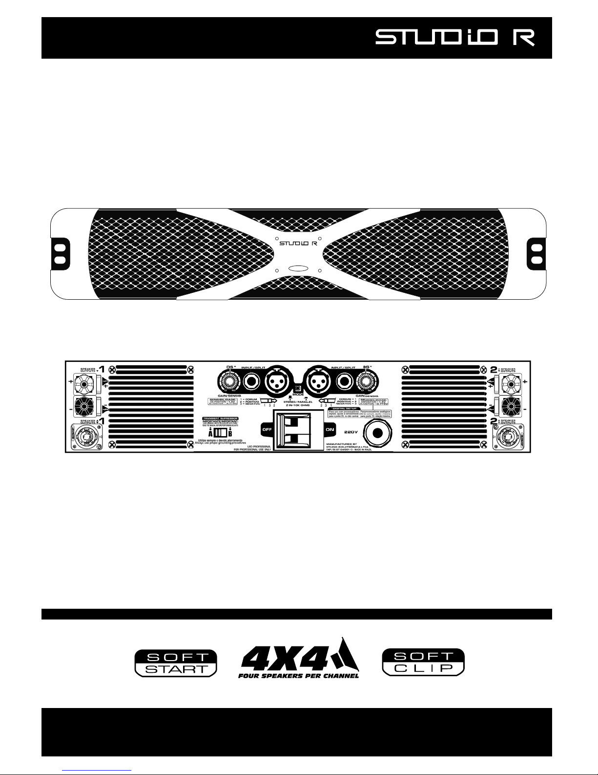
OWNER’S MANUAL
01/2009 - REV#5 -EN.
MODELS X1,X3,XD,X5,X8 and X12.
X SERIES
EURO VERSION / REGULAR VERSION
X5
www.studior.com.br
CH2
-
S
ig
nal
P
r
oc
essing
S
ign
a
l P
roc
essin
g
CH
1
5.600 WATTS RMS STEREO
L
eft
Ch
annel Sign
a
l
-
CH
1
CH
2 - Right Ch
annel S
ig
nal
POWER ON
Page 2
1
INTRODUCTION:
Congratulations for purchasing a STUDIO R X SERIES amplifier!
Our amplifiers are designed for many years of reliable operation at fixed or
movable facilities, under the strictest weather conditions.
The Studio R 3-year warranty
(valid for Brazil. Check with your dealer for local warranty):
A regular warranty usually covers the free repair of a product every time this fails
during a certain initial period of its lifetime. This procedure, although free of
charge, solves the problem of those components which have aged prematurely on
the product in a very costly and burdensome way for the customer. Many hours
are lost with the inoperative
system and its transportation.
Our concern with the warranty covering out products has never been that of
merely repair them promptly every time they present a fault, but also to prevent
faults for a long time during their lifetimes.
Studio R exclusive Burn-in:
Every Studio R amplifier is in-factory tested for three 3-hour cycles at full power
in a high-temperature oven. It is cooled and tested again at every interval. This
process is the only internationally proven way of finding components of a system
which could deteriorate prematurely
within the equipment lifetime.
Our current fault rate is 2 out of every 1000 devices produced, with a 5-year
time of regular use between two faults.
Such kind of product really allows you to amortize your investments safely and
still make profit. This is why we say that your amplifier should operate almost
seamlessly, while keeping the sonic quality and performance characterizing the
Studio R products.
Although it is basically simple to operate, and having been designed to be
endurable, the improper use of this equipment can be dangerous!
FOR YOUR SAFETY, READ THE SECTIONS ON IMPORTANT
PRECAUTIONS ABOUT INPUT, OUTPUT, AND POWER
CONNECTIONS.
Page 3
2
DANGER: THE OUTPUTS OF THIS AMPLIFIER CAN PRODUCE LETHAL VOLTAGE
LEVELS. NEVER MAKE CONNECTIONS WHILE THE DEVICE IS ON.
Wait for at least 1 minute after shutoff in order to carry out modifications in your connections.
WARNING: THIS EQUIPMENT IS CAPABLE OF PRODUCING HIGH SOUND
PRESSURE LEVELS WHEN CONNECTED TO SPEAKERS AND PEAKER SETS.
The continued exposure to high sound pressure levels may cause the permanent loss of or a
reduction in the hearing. Always work with your ears protected by appropriate attenuators.
1- IMPORTANT PRECAUTIONS: Read before operating your amplifier:
1.1 Keep this manual for future inquiries.
1.2 Follow all instructions printed on the chassis for the device proper
operation.
1.3 Make sure the power line is compatible with your device voltage by
checking on its back panel.
1.4 Do not spill liquids in or on the apparatus. Do not operate the
apparatus exposed to rain or with some spilled liquid. Such practice is
the main reason for lethal accidents caused by electric discharges.
1.5 Do not block the air inlet or outlet
. Do not operate in locations liable to
preventing the normal air flow.
1.6 Do not use this equipment in case any wire is stripped or fractured.
1.7
It is recommended to keep your amplifier frame always connected to a
grounding system; do this by means of the chassis bolt on the back
panel.
1.8 Do not activate the inputs with a power supply greater than the required
for the amplifier at maximum output.
1.9 Never connect the output of a channel back to the input of another
channel.
1.10 Do not connect the outputs in parallel with the outputs of any other
amplifier.
1.11 Do not connect the outputs of this equipment with any other power
supply, such as batteries or power line, either the equipment is ON or
OFF.
1.12
Do not connect any positive binding post to the ground.
1.13 Do not remove the covers.
On removing them you will be exposed to
dangerous voltages. Inside the equipment there is no useful part for the
user. In case any problem occurs, call your nearest technical assistance.
Technical support and information:
website: www.studior.com.br E-mail: [email protected]
Page 4

3
2-INSTALLATION AND OPERATION:
2.1 Unpacking
Open the transportation packing carefully and check for any apparent damage.
Prior to leaving the plant all Studio R amplifiers are fully tested and inspected and
ought to reach you in perfect conditions. Should any damage be found on them,
please notify the carrier immediately. Only a forwarding agent may request the
carrier to take actions concerning the damage occurred during the
transportation. Make sure to keep all packing for inspection. It might be a good
idea to keep the packing even when your amplifier has come in perfect conditions.
Whenever it has to be transported, use the original packing or rack standard
CASE, with frontal bars.
2.2 Assembling
Your amplifier is designed to be assembled on a standard 19” CASE, with 02
units/rack. For a movable use, in addition to 4 holes for assembly on the front
panel, also use the four holes located on the amplifier rear “grips”. The ventilation
on the apparatus rear portion and the front air outlet are essential for its proper
performance. This system provides enough cooling for all load rates, assuming
that the rack rear portion is open and unblocked. On racks with a closed rear
portion, it is vital to install additional fans on same in such a way to pressurize
them, ensuring a good air source for your amplifier internal fan.
2.3 Operating precautions.
Make sure the power line AC voltage is the appropriate for powering your X
Series amplifier
. The warranty does not cover damages resulting from using the
device on the wrong voltage.
Prior to making any connection, both regarding input and output, make sure that
the power switch is off. Even though the amplifier is fitted with overload
protection as well as a Soft Start (silent activation), it is recommendable to
always keep the gain controls low when turning it on. This operation will prevent
any possible damages to the speakers should there be an excess signal on the
inputs. Seek to acquire cables, connectors, and speaker of good quality and
appropriate capacity. Check the wiring capacity table (Section 2.5) to determine
the appropriate measures for different impedances and lengths of cables.
Most of the systems intermittences and faults
occur due to defective wires and connectors.
Use quality connectors, wires, and welding technique to ensure seamless
operations.
Page 5
4
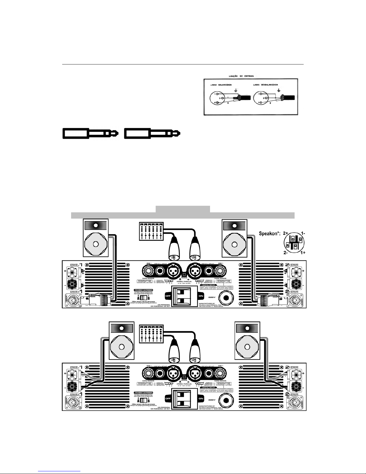
BALANCED UNBALANCED
2.4 Connecting the inputs
The input/split connections are performed by
means of two 3-pin, XLR-type and two
“P10”- type connectors, located on the rear
panel. The connection orientation is:
Pin 1 - Ground.
Pin 2 – Positive (phase).
Pin 3 – Negative (counter-phase).
Figures bellow shows the basic diagram for the rear connections using binding posts or
Speakon. You can connect the mixer L channel to the amp input 1, and the R channel to
the amplifier input 2, for example. The same precaution should be taken for connecting
the speakers. The speakers located on the right side of the stage should be connected to
the right channel (OUTPUT 2), and those of the other side on the left channel (OUTPUT 1).
The speaker polarity is very important. The speaker positive should be connected to the
amplifier + positive and the speaker negative to the amplifier - negative connection.
VERY IMPORTANT:
You can connect up to four 8 Ohm speakers per channel of an X Series amplifier!
* Always connect the speaker positive (+) to speakon’s pin 1+ or 2+ and the negative to pin 1- or 2-
(internally, both pins 1+ and 2+ are connected in parallel. Pins 1- and 2- are also internally in parallel).
BALANCED UNBALANCED
I I I
1 3 2
I I I
1 1 2
The X SERIES amplifiers contain
balanced inputs and can be powered
either by balanced lines or not,
according to the figures.
Page 6
5
2.5 Connecting the outputs:
The speakers should be connected to the amplifiers by wires which, in the first
place, are capable of the minimum current necessary for the work.
Wire minimum gauge in mm2
As we can see on the table below, in some instances, using only one wire to
convey the signal to the 4 speakers is complicated, as a quite thick wire is
required. The suggestion is to use one wire for each two speakers.
In addition to the current capacity of the speaker connecting wires, it is also
important to know the distance between the speakers and the amplifier. Even
with the proper gauge wire, we may have losses of power and damping factor on
long-distance connections.
On the table below, see the power loss in percentage and, in parentheses, the
resulting Damping Factor.
The drop in the Damping Factor occurs on any amplifier
by simply existing a wire between same and the speaker.
We can see in bold letters that the losses, in long distances, exceed 10% and that the damping
factor also drops below 10. For example, a 12% loss on a 3000-W amplifier causes a 360 W on
the wires, and the speakers receives only 2640 W.
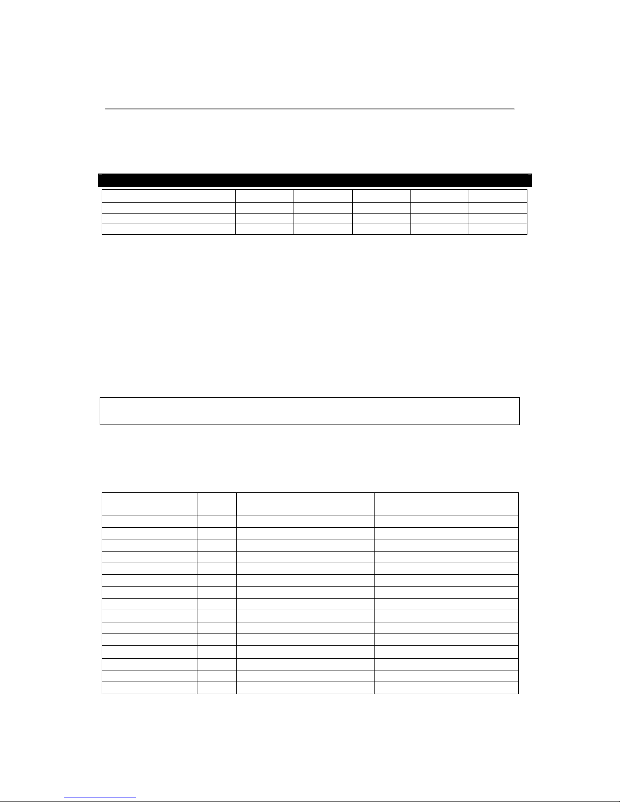
Length of the
wire pair
(m)
Gauge
(mm2)
Power loss on the wires
for each speaker
Power loss on the wires
for every 2 speakers
5 1 2.2% (45)
5 1.5 1.5% (67)
3% (34)
5 2.0 1% (90)
2.2% (45)
5 2.5 0.85% (114)
1.75% (57)
5 3 0.7% (140)
1.4% (66)
10 1 4.4% (23)
10 1.5 3% (34) 6% (16)
10 2.0 2% (46)
4.4% (25)
10 2.5 1.7% (57)
3.5% (28)
10 3 1.4% (66)
2.8% (33)
20 1 8.8% (11)
20 1.5 6.0% (16)
12% (8.3)
20 2.0 4% (22)
8.8% (11)
20 2.5 3.4% (28)
7% (10)
20 3 2.8% (33) 6% (16)
X1 X3 e XD X5 X8 X12
One wire for each speaker
1mm2 1,5mm2 2,5mm2 3 or 4mm2 4mm2
One wire for each two speakers
1,5mm2 2,5mm2 5mm2
One wire for the four speakers
3mm2 5mm2
Page 7
6
IMPORTANT: EXCLUSIVE 4X4 SYSTEM _________________________________________
The Studio R amplifiers allows 4 speakers to be used on each channel, causing
the amplifier to supply its maximum power on such conditions.
Actually, with 4 speakers per channel we have around 1.5 Ohm of actual load, not
the theoretical 2 Ohm. Other amps in the market are designed for a minimum
actual load of 2 Ohm and, thereby, do not operate properly with above 3 speakers
per channel. They play, but heat too much, activating the protection circuits and
dropping the power to values well below the specified minimum power.
When we use amplifiers designed for 2 Ohm, we are compelled to using maximum
3 speakers per channel, if we want to use their power to the fullest extent.
THIS DOES NOT OCCUR WITH THE STUDIO R. THAT’S ONE OF THE
REASONS WHY A STUDIO R ALWAYS PLAY LOUDER!
2.5.1 BINDING POSTS FOR THE SPEAKER WIRES.
We should use wires with “banana” or “fork” connectors, the second (fork) being
more reliable in the long run (the banana connector gets loose in a short time).
The speaker positive should be connected, and the binding post with red lug
regarded as “hot”, which should never be connected directly to the ground. The
other side of the speaker should be connected to the black lug.
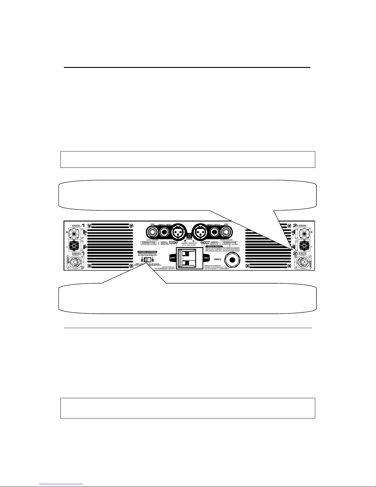
As we see, there is a pair of lugs on each amplifier output channel.
Never connect any wire directly between the left channel
lugs and those of the right channel and vice-versa.
Floating ground and Transient Supressor: Your amplifier circuit ground is insulated from the frame.
This allows various safety configurations to be made for the system grounding. For more information,
refer to the chapter 6.1 about the Transient Supressor bar and problems related to lightning systems.
SPEAKER OUTPUTS: This is where the speakers should be connected to (using Speakon or binding
posts). Connect the amplifier positive lug to the speaker positive and the amplifier negative lug to the
speaker negative. Output 1 should be connected to the system left side speakers, while output 2
should be connected to the system right side on stereo systems.
Page 8
7
2.6 Turning your X Series power on:
Your Studio R power cable has 3 wires and no connector. The user should check
the consumption table and, according to the intended use of his/her equipment,
purchase the male and female connector of your preference, with the appropriate
capacity for the length, power consumption and use. The power cable is available
in two different standards:
International: Brown=Hot, Blue=Neutral and Green=Ground.
American: Black=Fase, White=Neutral and Green=Ground.
The X Series amplifiers are designed to operate on one voltage only, selected in
factory according to user’s preference (available in 100, 115V, 127, 220, 230 or
240V - 50 / 60Hz) and indicated on the label attached to the cable or rear panel.
Under full power, with both channels set to 1.5 Ohm (4 speakers per channel),
your Studio R X Series amplifier may “pull” a considerable current. See on the
table below what is the minimum recommendable gauge to use on your AC power
installation according to the number of speakers to use and the type of music.
NOTE: THE TABLE VALUES WERE CALCULATED FOR 230 V, WITH A SETTING
BETTER THAN 5% (WHICH IS A SATISFACTORY SETTING), ON AN INSTALLATION
WITH NO MORE THAN 50 METERS BETWEEN THE POWER FRAME AND THE
AMPLIFIER.
When longer distance connections are required, such as for example 100 meters
(double the distance), we should use double the gauge as well.
In case of a sound system leasing company, where music is generally reproduced,
we should always size the AC system for the PINK NOISE rate:
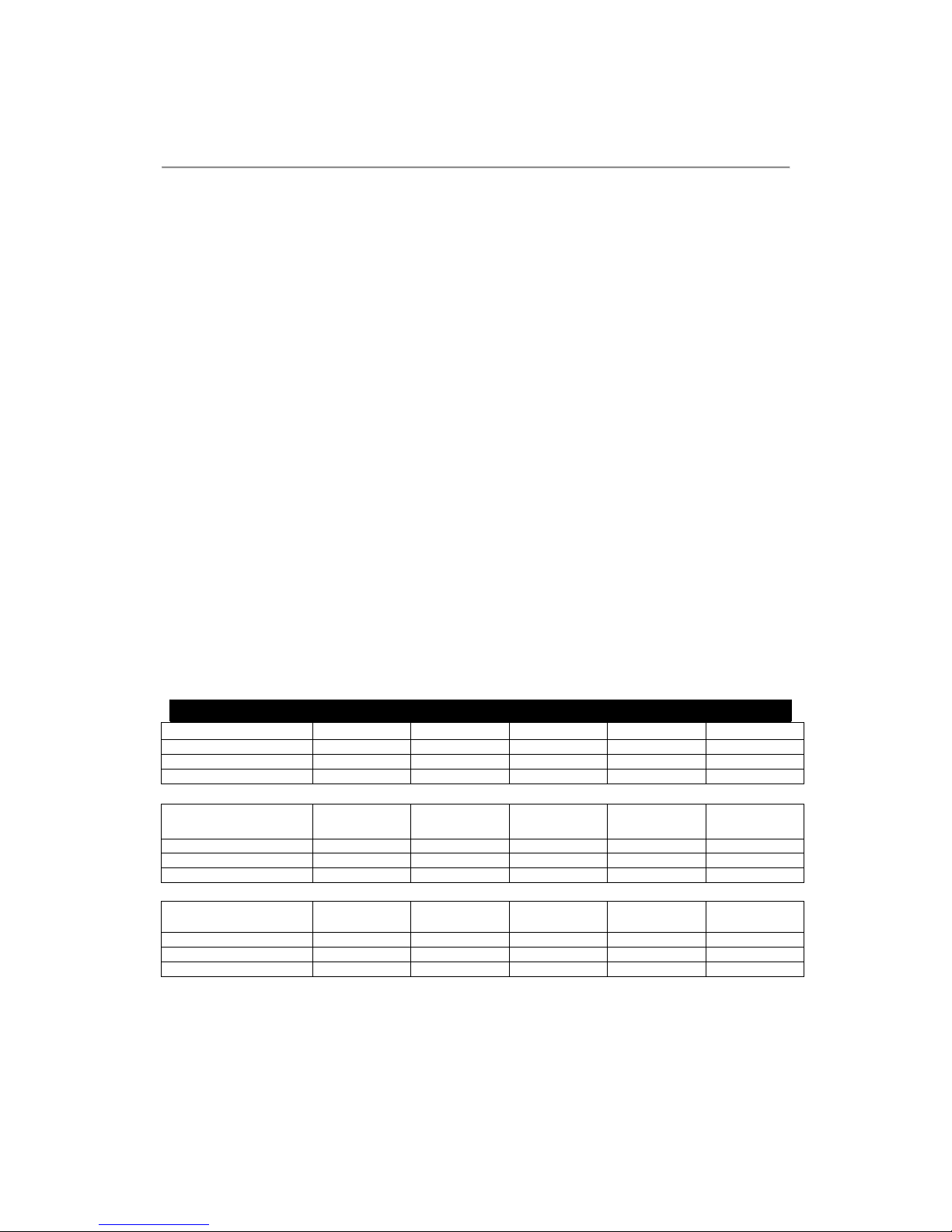
Wire gauges for 230V – 50/60Hz (multiply for 2 in 100 to 127V versions):
PINK NOISE
X1 X3 e XD
X5
X8 X12
4 speakers per channel 1,5mm2 3mm2 5mm2 8mm2 2 x 5mm2
2 speakers per channel 1mm2 2,5mm2 4mm2 6mm2 8mm
2
1 speaker per channel 1mm2 1,5mm2 3mm2 5mm2 6mm
2
ROCK WITH
COMPRESSION
X1 X3 e XD
X5
X8
X12
4 speakers per channel
1mm2 2,5mm
2
5mm
2
8mm2 2 x 5mm
2
2 speakers per channel
1mm2 2mm
2
4mm
2
6mm2 8mm
2
1 speaker per channel
1mm2 1,5mm
2
3mm
2
5mm2 6mm
2
AMBIENT MUSIC
X1 X3 e XD
X5
X8 X12
4 speakers per channel
1mm2 2mm
2
4mm
2
6mm2 8mm
2
2 speakers per channel
1mm2 1,5mm
2
3mm
2
5mm2 6mm
2
1 speaker per channel 0,75mm2 1,5mm2 2,5mm2 4mm2 5mm2
All STUDIO R X Series amplifiers come with power cable. The user should
check the consumption table and, according to the intended use of his/her
equipment, purchase the male and female connector with the appropriate
capacity for the length.
Page 9
8
2.7 Stereo Operation:
For stereo operation, place an audio signal on channel 1 input, with an amplitude
consistent with the amplifier sensitivity, (selectable according to the SDS table),
in order to produce a signal output on channel 1 output lugs, while a signal on the
2 will produce a signal output on 2.
SDS table (gain/sensitivity adjust):
Sensitivity
Euro Version Regular Version
DS (centered gain - “DS” point)
26dB / 20x 1.55V (X1=2V, X12=1,8V)
Maximum (gain at 10 position)
32dB / 40x 0.775V (X1=1V, X12=0,9V)
IMPORTANT: The 1.55V level (in regular versions) is equal to -6dBm or -6 dBU. You must
always use this level, instead of 0.775V, when using digital processors (2V for the X1). In other
cases, adjust according to your system sensitivity.
Both channels operate on a completely independent way, with their respective
input attenuators controlling the total levels. In order to distribute the signals to
other amplifiers we must use the XLR male outputs which are just below the
inputs.
2.8 Parallel operation:
Both channels, on the parallel mode, can be fed by a single input signal source
without the need for any bridge. The signal applied on the channel 1 “XLR” will
activate both sides with the signal on phase. The output connections are made on
the same way as the stereo mode via the channel and black lugs. Both input
attenuators remain active, allowing for different levels for the speakers of each
channel. The power specifications continue the same as in the stereo operating
mode.
Attention: With the input switch on the parallel mode we cannot feed the
amplifier inputs with distinct signals, as they will be short-circuited.
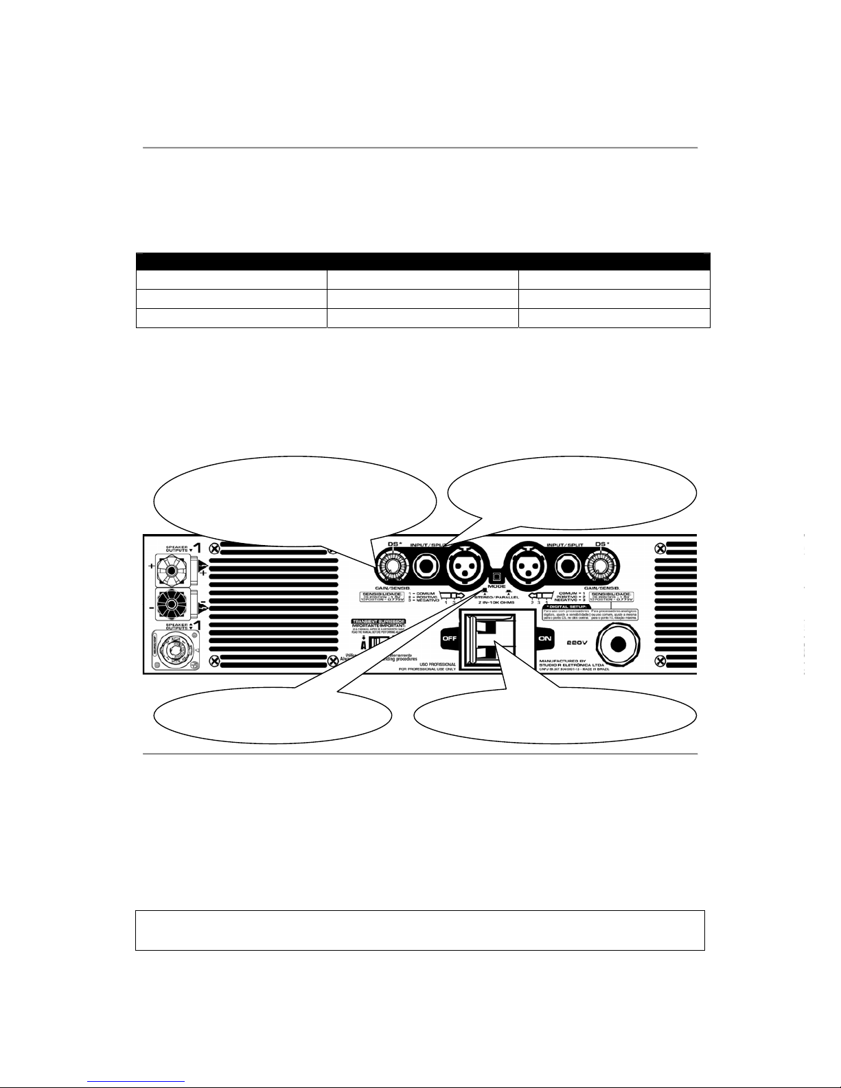
GAIN/SENSIB:
Input signal attenuators.
The controls operate separately
even on the
p
arallel operation.
Mode selector
STEREO or PARALLEL.
INPUT/SPLIT:
Balanced XLR and P10
inputs.
Power switch lever:
Turns the amplifier on and off.
Page 10
9
2.9 Input signal attenuators (GAIN/SENSIB).
The rotary controls located on the back panel of your Studio R, one for each
channel, allow the input sensitivity to be individually set with a reasonable
resolution. On the scale recorded on the panel from 0 to 10, the amplifier input
signal level on the stereo and parallel modes can be individually modified. When
fully turned on the clockwise direction, they will allow a signal on the input
sensitivity rate
32dB/40x (All Euro Version) or 0,775V (X3 to X8), 1V (X1) and
0,9V (X12) to provide a maximum power on a 2 or 1.5-ohm load. When at the
center click point (DS), sensitivity rate will be
26dB/20x (All Euro Version) or 1,55V
(X3 to X8), 2V (X1) and
1,8V (X12).
IMPORTANT: As the attenuators are independent, the channels can be set
with different signal levels. This occurs when each one of the channels are
being used for different environments or on different frequency ranges such as
bass and treble. (The speakers always withstand more power than the drivers.
Be careful with the settings!).
VERY IMPORTANT
THE INPUT SENSITIVITY CONTROLS OF THE X SERIES AMPLIFIERS ARE NOT
POWER SETTINGS (A HEAVY-DUTY LINE EXCLUSIVENESS!).
The regular setting of these will never be able to protect delicate speakers. In
these instances, an appropriate external limiter should be used.
3 - CONTROLS
3.1 Power Switch:
The ON/OFF switch of the Studio R X Series amplifiers are located on the rear
panel. In normal use, when the switch is turned to right, the amplifier is on and
one blue LEDs will light on the front panel.
ATTENTION
Prior to turning your amplifier on, make sure the power line voltage is the
same as the apparatus.
This is statistically the only way of damaging a Studio R. In addition, it is regarded
as a misuse and is not covered by the warranty.
Page 11
10
4 – INDICATORS:
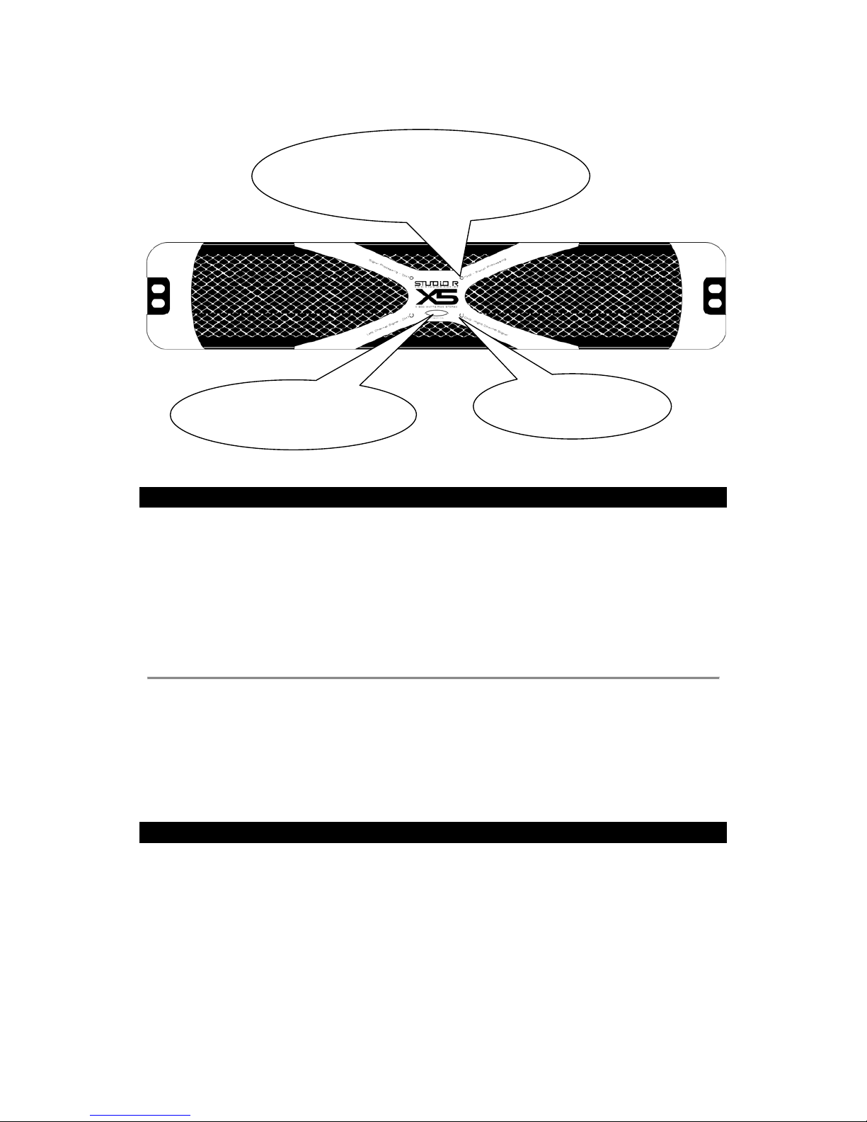
The Studio R X Series amplifiers are equipped with LED-type light indicators,
individual for each channel, which report the user on the operational condition. If
the power is on, the big blue LED “POWER” light up.
If a signal is present on the output, two green LEDs “SIGNAL” will flash
according to the signal on each one of the channels. When the maximum output
power is near to be reached, blue LEDs “PROCESSING” will light up according to
the intensity of the limiter acting and activation, as following detailed:
4.1 Processing indicators:
When the processing blue LED lights up, this indicates that the input signal
limitation has started. When the red LED flashes occasionally, a tolerable soft
limiting will be occurring. In case the input signal exceeds too much the input
nominal level, the limiter will start operating so as to avoid any distortions
greater than 2%.
5 - PROTECTION FEATURES
The Studio R X Series amplifiers incorporate several protection systems, both
for the amplifier and the speakers.
We seek to produce your amplifier on a “fail-safe” way, impenetrable by shortcircuits, open circuits, overloads, unequal loads, and damages due to overheating.
Under conditions where protection mechanisms are enabled, the operation stops
until the problem is cleared. See the following:
Power indicator:
Light up when the power
switch is on.
Signal processing indicators to
prevent distortions:
Flashing slightly when the amplifier is
next to full
p
ower is normal.
Amplifier output
signal indicators.
Page 12

11
5.1 Impedance sensor:
All Studio R amplifiers are provided with a system to assess the load type on
their output. In view of an excess load, this limits the maximum output current
without causing any severe distortions.
5.2 Thermal Protection:
Studio R amplifier dissipator is the most effective available in the market. It
provides double the required thermal capacity and its internal fan will keep the
amplifier operating within the desired temperature limits under normal conditions.
Should the temperature (or heat dissipator) reach 95º C due to an improper air
supply, air input or output blocking, or else due to the breakdown of its own fan, a
thermal sensor will be enabled in such a way to protect each channel individually
until the temperature returns to an acceptable level.
5.3 Short-circuit:
Should a short-circuit be applied to an output, the limiter and thermal circuits will
protect the amplifier.
5.4 Fuses:
The X Series amplifiers are fitted with a magnetic actuation circuit breaker which
eliminates the need for using line fuses. Assuming an accident occurs where the
amplifier output electronics are severely damaged, your amplifier still relies on
internal fuses which prevent the fault from propagating to other system portions.
The stoppage of one of the channels never interferes in the operation of the
other channel.
Soft Start.
When you turn on a Studio R X Series amplifier, its circuits are powered on a
symmetrical and completely silent way. Always wait at least 10 seconds before
each amplifier’s switching on and switching off to avoid overloads.
Dual Opto-limiter.
With the X Series limiter, you will always be able to use your PA under full power,
avoiding any distortion. Even when the line power is quite altered, your Studio R
will know how to dispense the power in order to eliminate any audible distortion.
Page 13
12
6 – SPEAKER PROTECTION METHODS:
The X Series amplifiers contains a adjustable 18dB/octave High-Pass filter,
default selected in 30Hz.
All speakers present physical limits. The most critical ones are the thermal and
mechanical limits, which should be observed so as to avoid its operation
stoppage.
Studio R amplifiers contain energy enough to damage most of the speakers
existing in the market without much effort, if misused.
Make sure that the frequency range used is appropriate for the speaker,
particularly the subsonic frequencies which are not reproduced by the
speaker. Always set your crossover to the ideal frequencies. Check the
speaker manual for determining the maximum “X” and “f3”.
) TIP: Ask for the service leaflet to the speaker manufacturer
in order for your own technician to master the subject.
Never power DRIVERS and TWEETERS without
an appropriate series capacitor!
For drivers, an optimum value is 47 micro Faraday.
For most of the tweeters, a 5.6uF capacitor is appropriate.
6.1 – THE TRANSIENT SUPRESSOR AUXILIAR SYSTEM:
The Transient Supressor switch (see amplifier’s rear panel), activates, when
turned connected, additional protection for transients usually generated by
lighting systems, for example. When switched to “B” and additional protection
against transients that are usually generated by lighting equipment is activated.
When switched to “A” it connects the system common to the chassis.
Attention: The transient supressor works only with the amplifier grounded
properly, otherwise, it must be not used, but ungrounded use is NEVER
RECOMENDED in order to prevent the risk of shock or fire hazard. Always check
to see that the amplifiers are properly grounded.
7 – MAINTENANCE:
Your Studio R amplifier does not require much maintenance, which is restricted
to its outer cleaning and cooling system eventual hindrance removal. Do not use
any solvent, but only a cloth wet with water and soap. The amplifier should not
require any internal adjustment during its lifetime.
NEVER BLOW COMPRESSED AIR INTO THE AMPLIFIER
ELECTRONICS OR ANY OTHER SIMILAR EQUIPMENT.
Page 14
13
8 – USER RESPONSIBILITY:
YOUR AMPLIFIER IS QUITE POWERFUL
AND CAN BE POTENTIALLY DANGEROUS!
STUDIO R IS NOT RESPONSIBLE FOR ANY DAMAGE CAUSED TO HUMANS OR
SPEAKERS. FOLLOW CAREFULLY THE INSTRUCTIONS SET FORTH IN THE
MANUAL AND THE RELEVANT STANDARDS RELATED TO YOUR INDUSTRY.
9 – WARRANTY::
Studio R provides the purchaser of any X Series amplifier with a warranty
against defects on the components and assembly for a 3-year*** time as of the
purchasing date (***Valid for Brazil. Please check with your dealer about local warraty).
IMPORTANT:
Studio R reserves the right to introduce changes or improvements into the
design and manufacturing of its amplifiers, without undertaking any obligation to
do so in the previously manufactured products.
Do not forget to send us the registration sheet already filled out to make it
easier for serving you and sending information and future novelties. Such
registration can also be made on our site: www.studior.com.br
In the event you are unable to install or to take the best profit you expect from
your equipment, get in touch with our International Technical Support:
STUDIO R Eletronica LTDA
Rua Lucrecia Maciel, 95 – Vl Guarani. CEP 04314-130
Sao Paulo, SP – Brazil
+55 (011) 5015-3600.
Visit our website: http://www.studior.com.br
E-mail: [email protected]
Page 15
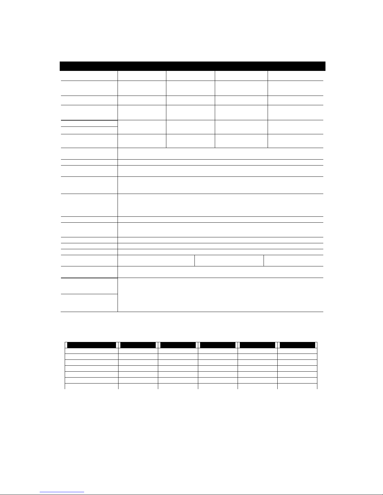
14
General Specifications: 230V 60 Hz or 127V 60 Hz power line
CLASSIFICATION
X1: Class AB
High-polarization
XD:
Class AB
High-polarization
X3-X5: Class AB
variable
X8-X12: Class H
MOSFET
HARMONIC DISTORTION
1KHz @ 1/2 of rated power
X1: 0,015%, 2 Ohm
0,008%, 4 Ohm
0,005%, 8 Ohm
XD:
0,02%, 2 Ohm
0,015%, 4 Ohm
0,008%, 8 Ohm
X3-X5: 0,09%, 2 Ohm
0,05%, 4 Ohm
0,02%, 8 Ohm
X8-X12: 0,1%, 2 Ohm
0,07%, 4 Ohm
0,04%, 8 Ohm
HARMONIC DISTORTION
20Hz-20KHz @ rated power
X1: less than 0,025% XD: less than 0,025% X3-X5: less than 0,9% X8-X12: less than 1%
FREQUENCY RESPONSE
X1: 20Hz to 20khz
+/- 0,5dB.
Programable
XD:
20Hz to 20khz
+/- 0,5dB.
Programable
X3-X5: 20Hz to 20khz
+/- 0,5dB.
Programable
X8-X12: 20Hz to 20khz
+/- 0,5dB.
Programable
DAMPING FACTOR
X1: >2000 @ 8 Ohm
from 40 to 165Hz.
>1000 to 10kHz
XD:
>2000 @ 8 Ohm
from 40 to 165Hz.
>800 to 10kHz
X3-X5: >2000
@ 8 Ohm
from 40 to 165Hz.
X8-X12: >2000
@ 8 Ohm
from 40 to 165Hz.
NOISE
X1: 105
dBA related to
the max. rated
power output.
XD: 105
dBA related to
the max. rated
power output
X8: 100 dBA related to
the max. rated
power output.
X1: 100 dBA related to
the max. rated
power output.
SENSITIVITY
32dB / 40x or 26dB / 20x selectable.
See SDS table, page 8.
INPUT IMPEDANCE
10 KOhm balanced
CONTROLS
Rear: Power switch, stereo/parallel switch, rotary settings for the
input signal attenuation.
INDICATORS
Power - 1 blue LEDs
Signal - 2 green LEDs
Processing - 2 blue LEDs
CONNECTORS
Line inputs and outputs: 2 XLR female connectors and 2 P10 female connectors,
balanced (pin 1 and 3 ground, 2” +”).
Transient supressor, floating ground and chassis connecting bar.
Speakers: 2 pairs of 1/4’ lugs (one pair for each channel) and Speakon.
COOLING
Dual aluminum duct with forced ventilation.
PROTECTION
Dual opto-limiter, Soft Start, short-circuited or open output, reactive or mismatched
loads, and over the input signal. Independent thermal sensors for each channel.
LOAD PROTECTION
silent ON/OFF, DC on the output
OUTPUT CIRCUIT
Linear complementary, Soft Clip.
POWER
Available in 100, 115, 127, 220, 230 or 240V - 50/60Hz versions.
PRECISE CONSUMPTION
X1-XD: 1.55 times the output
power used.
X3-X5: 1.35 times the
output power used.
X8-X12: 1.3 times the
output power used.
DIMENSONS
(height x width x depth)
X1 to X8: 88.9mm x 483mm x 325mm (+ 45mm for rear support ears).
X12: 88,9mm x 483mm x 440mm (+ 45mm for rear support ears).
WEIGHT/RATED POWER
and MAXIMUM
CONSUMPTION
X1 = 15.5kg/ 1200 W. 220V-10A (20A for 115 to 127V versions)
XD = 15,5kg/ 3600 W. 220V-21A (42A for 115 to 127V versions)
X3 = 16kg/ 3600 W. 220V-21A (42A for 115 to 127V versions)
X5 = 16kg/ 5600 W. 220V-32A (64A for 115 to 127V versions)
X8 = 16kg/ 8000 W. 220V-50A (100A for 115 to 127V versions)
X12 = 17kg/ 11.000 W, 220V-68A (136A for 115 to 127V versions)
SINUSOIDAL POWER TABLE (Watts RMS): Valid for 230V/60Hz line, harmonic distortion 1% to 1
KHz. For line voltage variations of 10%, the powers may vary up to + or – 22% (IEC268 Standard).
Model/Condition X1 X3 e XD X5 X8
X12
2 Ohm-2 channels 1.200W 3.600W 5.600W 8.000W 11.000W
4 Ohm-2 channels 1.000W 2.240W
3.500W
4.700W 6.400W
8 Ohm-2 channels 600W 1.280W
2.000W
2.600W 3.500W
2 Ohm-1 channel 700W 2.150W
3.340W
4.200W 5.700W
4 Ohm-1 channel 420W 1.250W 1.950W 2.500W 3.500W
8 Ohm-1 channel 360W 700W 1.100W 1.380W 1.900W
1.5 Ohm-2 channels
1.200W 3.600W 5.600W 8.600W 13.000W
 Loading...