

Page 1
TO MIXER:
LINE-IN
-OR-
TO MIXER:
TAPE-IN
FROM RECORDER:
PLAY-OUT
TO RECORDER:
RECORD-IN
NOTE: RCA connections shown, but use the correct
cable and connectors for your particular setup.
Connections to the 1/4” TRS Insert Plug:
RING= Hot
SLEEVE= Ground
Insert
Return
TIP= Hot
SLEEVE= Ground
Insert
Send
STUDIO PROJECTS
(OR OTHER HI-QUALITY)
MICROPHONE
Studio
Projects
NOTE: Plugging into the Insert
Jack interupts the normal signal
flow thru the VTB-1. If the
recorder is OFF, or no playback
is available, no signal will show
in the meter (OUT) or be
present at the Bal Out or Line
Out of the VTB-1.
NOTE: Microphone
12VAC
input shown, but this
setup works the same
way for Line-In signals.
Use the front-panel
jack and switch to bring
instruments into the
VTB-1.
48
Volt
Studio Projects
Insert Plug
Balanced
Out
Line Out
RECORD PLAY
HPF
Line
Input
Gain
25
30
20
In
40
6
50
0
60
70Hz
Blend
1
2
3
4
SS Tube
Line In Tube
1/4” TRS
Insert
Tip=Send
Ring=Return
Meter
=
1
2
Output
3
Input
4
SLEEVE
RING
TIP
200Ω
50Ω
Mic
Impedance
Level
-8 0 +8 +15-20
Mic
In
Output
Level
0
+–
6
6
12
•
Tube Mic Pre
Pol
Rev
C1
Studio Condenser
VTB-1
REAR CONNECTIONS
VTB-1
FRONT CONTROLS
INPUT GAIN: SETS THE LEVEL OF
SIGNAL FEEDING THE RECORDER
HI-PASS FILTER: AFFECTS SIGNAL
GOING TO THE RECORDER
TUBE-BLEND: ONLY AFFECTS THE SIGNAL
RETURNING FROM THE RECORDER
METER SELECT: LETS YOU VIEW THE
SIGNAL GOING TO THE RECORDER (IN),
OR FEEDING THE MIXER (OUT)
NOTE: The VTB-1 meter is calibrated
for Pro level operation (+4dBu). The
meter may stay in its lower ranges when
driving semi-pro gear (-10dBV levels).
If your equipment has a level-select
switch, set it for +4 operation for best
results and quietest operation.
OUTPUT LEVEL: SETS THE AMOUNT OF
RETURNED SIGNAL FEEDING THE MIXER
POLARITY REVERSE: INVERTS THE
POLARITY (PHASE) OF THE SIGNAL
FEEDING THE MIXER
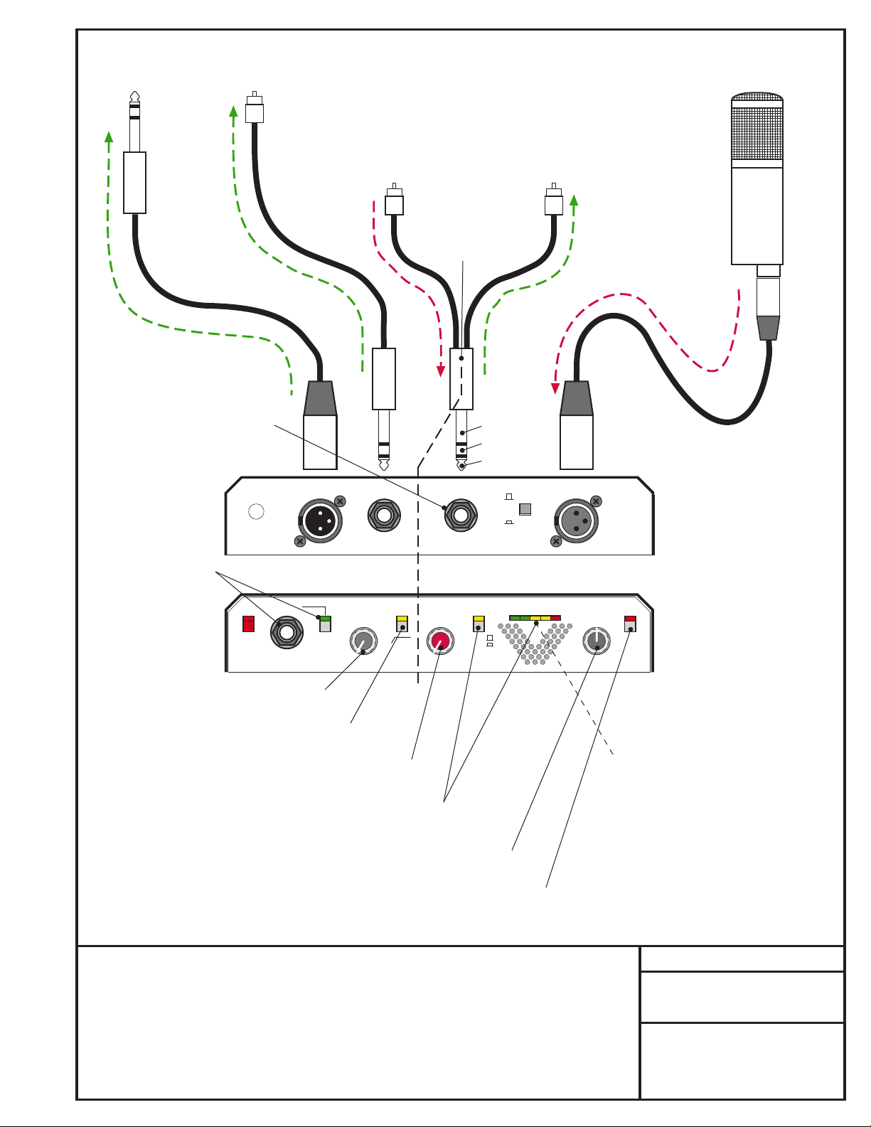
Because of its specially designed signal path, the VTB-1 can be used to both feed and
monitor a recorded track using its Insert Jack. The insert point is after the HPF, but
directly before the Blend Control. The signal feed from the insert jack is before any tube
circuitry, so the recorded signal will always be a SS only signal. The Playback output
from the Recorder uses the return path of the insert jack which directly feeds the Tube
Blend control and then the Output Level pot. By using the Blend control, the user can
add the desired amount of Tube Sound at the final mix stage instead of when tracking.
This allows for more variety during mixdown and contributes to less finger-pointing when
it’s decided that the sound you originally recorded is not really what you want now.
STUDIO PROJECTS
VTB-1 HOOKUP DIAGRAM
Using the VTB-1 for feeding and
monitoring a recorded track
Using the VTB-1 for clean
recording, with the option of
adding “Tube Sound” to the
track during mixdown.
Page 2
ENHANCED OUTPUT:
To Recorder or Mixer.
Affected by Gain
and HPF controls
PLUS
the Blend, Output and
Polarity Controls
NOTE: Plugging into the Insert
Jack interupts the normal signal
flow thru the VTB-1. If the jack
is not wired with the TIP and
RING tied together, no signal
will show on the meter (OUT)
or be present at the Bal Out or
Line Out of the VTB-1.
NOTE: Microphone
input shown, but this
setup works the same
way for Line-In signals.
Use the front-panel
jack and switch to bring
instruments into the
VTB-1.
12VAC
48
Volt
Studio Projects
CLEAN OUTPUT:
To Recorder or Mixer.
Only affected by GAIN
and HPF controls.
NO TUBE SOUND
Connections to the
1/4” TRS Insert Plug:
TIP & RING= Hot
SLEEVE= Ground
NOTE: TIP & RING
tied together
1/4” TRS
Insert Plug
Balanced
Out
Line In Tube
Line
In
20
6
Line Out
Input
Gain
25
0
HPF
Blend
70Hz
1
2
3
4
SS Tube
30
40
50
60
Insert
Tip=Send
Ring=Return
=
1
2
3
4
SLEEVE
RING
TIP
Meter
Output
Input
200Ω
50Ω
Mic
Impedance
Level
-8 0 +8 +15-20
NOTE: 1/4” connectors
shown, but use the
correct cable and
connectors for your
particular setup.
Mic
In
VTB-1
REAR CONNECTIONS
Output
Level
0
+–
6
6
Tube Mic Pre
Pol
Rev
12
•
VTB-1
FRONT CONTROLS
STUDIO PROJECTS
(OR OTHER HI-QUALITY)
MICROPHONE
Studio
Projects
C1
Studio Condenser
INPUT GAIN: CONTROLS THE LEVEL
OF BOTH OUTPUTS
HI-PASS FILTER: AFFECTS SIGNAL
GOING TO BOTH OUTPUTS
TUBE-BLEND: ONLY AFFECTS THE ENHANCED
OUTPUT. USE IT TO ADD TUBE COLORING TO
THE ENHANCED OUTPUT
METER SELECT: LETS YOU VIEW EITHER
OF THE SIGNALS. CLEAN (IN),
OR ENHANCED (OUT)
OUTPUT: SETS THE LEVEL OF THE
NOTE: The VTB-1 meter is calibrated
for Pro level operation (+4dBu). The
meter may stay in its lower ranges when
driving semi-pro gear (-10dBV levels).
If your equipment has a level-select
switch, set it for +4 operation for best
results and quietest operation.
ENHANCED OUTPUT ONLY
POLARITY REVERSE: INVERTS THE
POLARITY (PHASE) OF THE ENHANCED
OUTPUTS ONLY
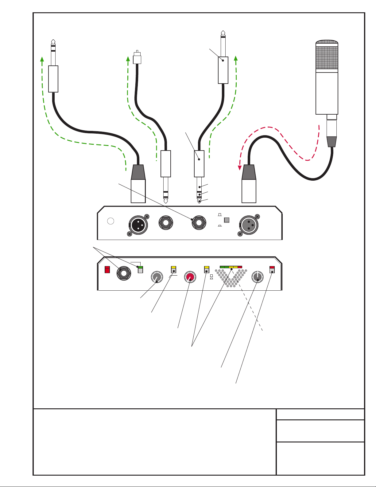
Because of its specially designed signal path, the VTB-1 can be used to generate two
distinct outputs by using its Insert Jack as an additional output. The insert point is after
the HPF, but directly before the Blend Control. The signal feed from the insert jack is
before any tube circuitry, so the additional output will always be a SS only signal. The
insert cable needs to be wired as a “Borrow Cable” by tying the Tip and Ring connections
together. This allows the insert signal to feed the outside world but still continue through
the VTB-1 in its normal way. By using the Blend control, the user can add the desired
amount of Tube Sound to the main (Enhanced) outputs while still having a clean, all
solid-state output also available.
STUDIO PROJECTS
VTB-1 HOOKUP DIAGRAM
Using the VTB-1 for generating
two different sounding feeds.
Using the VTB-1’s Insert jack,
a clean (all SS) signal, as well
as a Tube Sound signal, can
be simultaneously generated.
Page 3

TO RECORDER OR MIXER:
LINE-IN
- EXTERNAL PROCESSING UNIT -
Line InLine Out
STUDIO PROJECTS
(OR OTHER HI-QUALITY)
MICROPHONE
-OR-
NOTE: Plugging into the Insert
Jack interupts the normal signal
flow thru the VTB-1. If the Ext
Gear is OFF, or its output is
muted, no signal will show in
the meter (OUT) or be present
at the Bal Out or Line Out of
the VTB-1.
NOTE: Microphone
input shown, but this
setup works the same
way for Line-In signals.
Use the front-panel
jack and switch to bring
instruments into the
VTB-1.
12VAC
48
Volt
Studio Projects
Connections to the
1/4” TRS Insert Plug:
SLEEVE= Ground
Insert
Return
RING= Hot
SLEEVE= Ground
Insert Plug
Balanced
Out
Line In Tube
Line
In
20
6
Line Out
Input
Gain
25
0
HPF
Blend
70Hz
1
2
3
4
SS Tube
30
40
50
60
1/4” TRS
Insert
Tip=Send
Ring=Return
Meter
=
1
2
Output
3
Input
4
TIP= Hot
SLEEVE
RING
TIP
200Ω
50Ω
Mic
Impedance
-8 0 +8 +15-20
Level
NOTE: 1/4” connectors
shown, but use the
correct cable and
connectors for your
particular setup.
Insert
Send
Mic
In
VTB-1
REAR CONNECTIONS
Output
Level
0
+–
6
6
Tube Mic Pre
Pol
Rev
12
•
VTB-1
FRONT CONTROLS
Studio
Projects
C1
Studio Condenser
INPUT GAIN: SETS THE LEVEL OF
SIGNAL FEEDING THE EXT GEAR
HI-PASS FILTER: AFFECTS SIGNAL
GOING TO THE EXTERNAL GEAR
TUBE-BLEND: AFFECTS THE SIGNAL
RETURNING FROM THE EXT GEAR
METER SELECT: LETS YOU VIEW SIGNAL GOING
TO THE EXTERNAL GEAR (IN),
OR FEEDING THE RECORDER (OUT)
NOTE: The VTB-1 meter is calibrated
for Pro level operation (+4dBu). The
meter may stay in its lower ranges when
driving semi-pro gear (-10dBV levels).
If your equipment has a level-select
switch, set it for +4 operation for best
results and quietest operation.
OUTPUT LEVEL: SETS THE AMOUNT OF
PROCESSED SIGNAL FEEDING THE RECORDER
POLARITY REVERSE: INVERTS THE
POLARITY (PHASE) OF THE SIGNAL
FEEDING THE RECORDER
Often, when recording, additional control is desired when tracking a signal. Most external processing
gear is designed for line-level operation and will not operate properly if fed directly from a
microphone-level input signal. The VTB-1 provides an Insert Jack at line-level strength to properly
interface to most gear. The Insert send-point is directly after the SS preamp and Hi-Pass filter
sections, the return-point feeds the Tube Blend control. The Insert Jack is a 1/4” TRS jack and
is wired as Tip= Insert-send, Ring= Insert-return, Sleeve= Ground. The nominal operating level
at this point is approx 0dBu. When a compressor is being used, use the Meter (IN) to monitor the
internal level and use the Gain control to set the SS preamp to a conservative level (keep levels
below 0 on the meter). This leaves more headroom in the first, critical stage. Then use the controls
of the external compressor to keep the dynamics within the desired range.
STUDIO PROJECTS
VTB-1 HOOKUP DIAGRAM
Using external processing gear
with the VTB-1
Add an equalizer, compressor
or other equipment to the
signal path before recording.
 Loading...