

XPA 40
Professional Power Amplifier
0 10
CH A
0 10
CH B
XPA 40
POWER
Index
1...........................................................................................................................................................................................Warranty Information
2...........................................................................................................................................................................................................Introduction
3...........................................................................................................................................................................................Features at a Glance
4...........................................................................................................................................................................Front & Rear Panel Description
5..............................................................................................................................................................................................Wiring Information
6................................................................................................................................................................................... ..........System Application
7......................................................................................................................................................................................................Block Diagram
8...................................................................................................................................................................................Protections & Installations
9.................................................................................................................................................................................................Trouble Shooting
10.....................................................................................................................................................................................Technical Specifications
Explanation of Graphical Symbols
CAUTION
RISK OF ELECTRIC SHOCK
DO NOT OPEN
CAUTION: TO REDUCE THE RISK OF
ELECTRIC SHOCK, DO NOT REMOVE
COVER (OR BACK). NO USER-SERVICEABLE
PARTS INSIDE. REFER SERVICING TO
QUALIFIED SERVICE PERSONNEL.
IMPORTANT SAFETY INSTRUCTIONS
The lightning flash with arrowhead symbol
within an equilateral triangle is intended to
alert the user to the presence of uninsulated
“dangerous voltage” within the product’s
enclosure that may be of sufficient magnitude
to constitute a risk of electric shock to persons.
The exclamation point within an equilateral
triangle is intended to alert the user to the presence of important operating and maintenance
(servicing) instructions in the literature
accompanying the product.
WARNING
TO REDUCE THE RISK OF FIRE OR ELECTRIC SHOCK,
DO NOT EXPOSE THIS APPARATUS TO RAIN OR MOISTURE.
IMPORTANT NOTICE
Connecting the Plug and Cord
WARNING: THIS APPARATUS MUST BE EARTHED
IMPORTANT. The wires in this mains lead are coloured in accordance
with the following code:
GREEN-AND-YELLOW: EARTH
BLUE: NEUTRAL
BROWN: LIVE
As the colours of the wires in the mains lead of this apparatus may not
correspond with the coloured markings identifying the terminals in
your plug proceed as follows:
The wire which is coloured GREEN-and-YELLOW must be connected
to the terminal in the plug which is marked by the letter E or by the
safety earth symbol or colored GREEN or GREEN-and-YELLOW.
The wire which is coloured BLUE must be connected to the terminal
which is marked with the letter N or coloured BLACK.
The wire which is coloured BROWN must be connected to the terminal
which is marked with the letter L or coloured RED.
1 Read these instructions.
2 Keep these instructions.
3 Heed all warnings.
4 Follow all instructions.
5 Do not use this apparatus near water.
6 Clean only with dry cloth.
7 Do not block any ventilation openings. Install in
accordance with the manufacturer’s instructions.
8 Do not install near any heat sources such as
radiators, heat registers, stoves, or other apparatus
(including amplifiers) that produce heat.
9 Protect the power cord from being walked on or
pinched particularly at plugs, convenience
receptacles, and the point where they exit from the
apparatus.
10 Only use attachments/accessories specified by the
manufacturer.
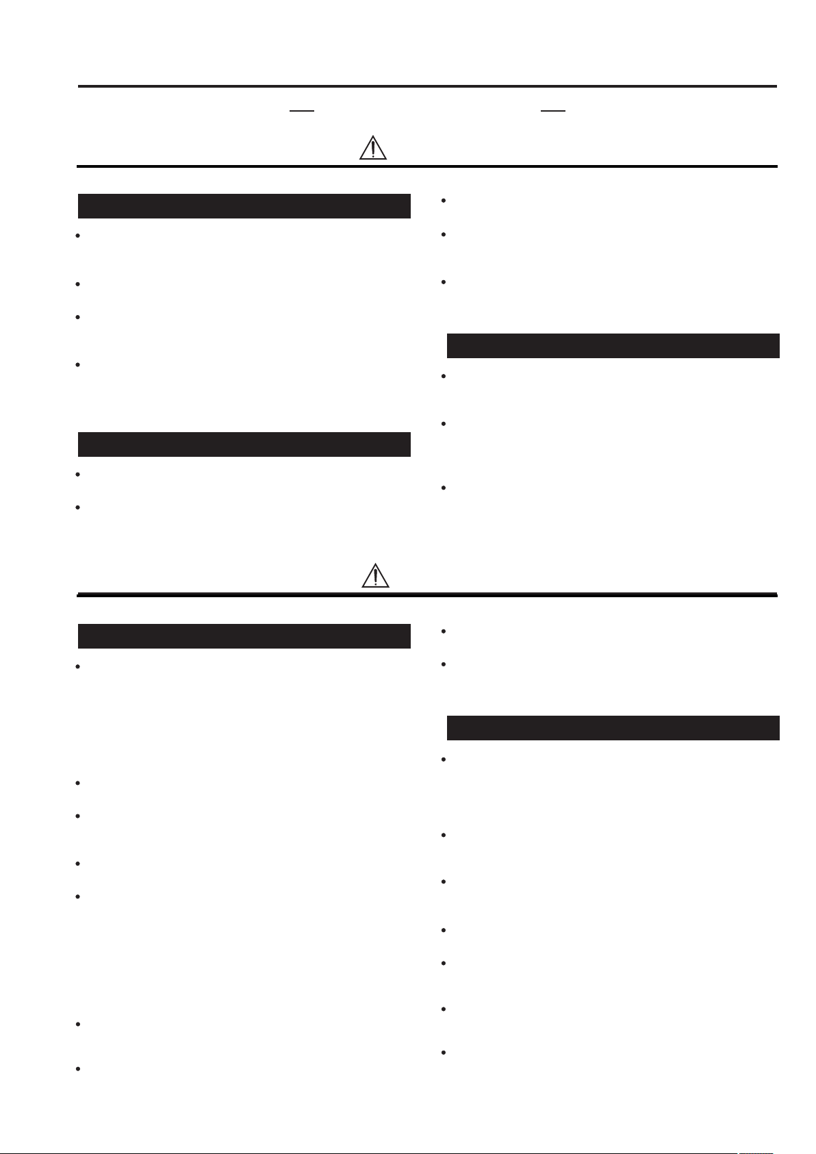
11 Use only with the cart, stand,
tripod, bracket, or table spec ified by the manufacturer, or
sold with the apparatus.
When a cart is used, use cau tion when moving the cart/
apparatus combination to
avoid injury from tip-over.
12 Unplug this apparatus during lightning storms or when
unused for long periods of time.
13 Refer all servicing to qualified service personnel.
Servicing in any way, such as power supply cord or
plug is damaged, liquid has been spilled or objects
have fallen into the apparatus, the apparatus has been
exposed to rain or moisture. does not operate normally,
or has been dropped.
Tips for Safe Operation
The 3 core AC mains cable should be terminated with this
AC mains plug by connecting brown/red wire on live pin
(L), black wire on neutral pin (N) and yellow/green wire
on earth pin (E).
The amplifier must be connected to an AC earthed mains
oultet that can delivered the maximum power required.
The use of extension cables or adaptors should be avoided
as this can jeoparadize correct delivery to the amplifier.
All connections must only be carried out or changed with
the amplifier switched OFF.
Ensure proper impedance matching while in use for BRIDGE
mode applications. For continous safe operation, resultant
impedance of the speakers 8 ohm/4 ohm is recommended.
For 2 ohm/4 ohm applications, it is recommended to use
speakon connectors only. Use of cable 40/36 or thicker is
recommended to prevent power losses.
The level of input signal should not exceed the specified
input sensitivities. Excessive input signal level result in
over driving of input circuit which leads to saturated /
distorted output at speaker terminals.
Do not operate the amplifier with continuously blinking
CLIP LED. The respective volume control of the channels
must be adjusted so that the output level does not clip and
distort.
Do not obstruct the front or back of the amplifier
for necessary intake of air.
2
Precautions
For safe operation
WARNING
Installation
Connect this unit’s power cord only to an AC outlet of the type
stated in this Owner’s Manual or as marked on the unit. Failure
to do so is a re and electrical shock hazard.
Do not allow water to enter this unit or allow the unit to become
wet. Fire or electrical shock may result.
Do not place a container with liquid or small metal objects on
top of this unit. Liquid or metal objects inside this unit are a re
and electrical shock hazard.
Do not place heavy objects, including this unit, on top of the
power cord. A damaged power cord is a re and electrical shock
hazard. In particular, be careful not to place heavy objects on a
power cord covered by a carpet.
Operation
Do not scratch, bend, twist, pull, or heat the power cord. A damaged power cord is a re and electrical shock hazard.
Do not remove the unit’s cover. You could receive an electrical
shock. If you think internal inspection, maintenance, or repair is
necessary, contact your dealer.
CAUTION
Do not modify the unit. Doing so is a re and electrical shock
hazard.
If lightning begins to occur, turn off the power switch of the unit
as soon as possible, and unplug the power cable from the electrical
outlet.
If there is a possibility of lightning, do not touch the power cable
plug if it is still connected. Doing so may be an electrical shock
hazard.
In case an abnormality occurs during operation
If the power cord is damaged (i.e., cut or a bare wire is exposed),
ask your dealer for a replacement. Using the unit with a damaged
power cord is a re and electrical shock hazard.
Should this unit be dropped or the cabinet be damaged, turn the
power switch off, remove the power plug from the AC outlet, and
contact your dealer. If you continue using the unit without heeding this instruction, re or electrical shock may result.
If you notice any abnormality, such as smoke, odor, or noise, or
if a foreign object or liquid gets inside the unit, turn it off immediately. Remove the power cord from the AC outlet. Consult your
dealer for repair. Using the unit in this condition is a re and
electrical shock hazard.
Installation
Keep this unit away from the following locations:
- Locations exposed to oil splashes or steam, such as near cooking stoves, humidiers, etc.
- Unstable surfaces, such as a wobbly table or slope.
- Locations exposed to excessive heat, such as inside a car with
all the windows closed, or places that receive direct sunlight.
- Locations subject to excessive humidity or dust accumulation.
Do not place the power cord close to a heater. It may melt, causing re or electrical shock.
Hold the power cord plug when disconnecting it from an AC outlet. Never pull the cord. A damaged power cord is a potential re
and electrical shock hazard.
Do not touch the power plug with wet hands. Doing so is a
potential electrical shock hazard.
This unit has ventilation holes at the front, rear & top to prevent
the internal temperature rising too high. Do not block them.
Blocked ventilation holes are a re hazard.
In particular, do not
- place the unit on its side or upside down,
- place the unit in any poorly-ventilated location such as a
bookcase or closet (other than on the dedicated rack),
- cover the unit with a table cloth or place it on a carpet or bed.
Allow enough free space around the unit for normal ventilation.
This should be: 5 cm at the sides, 10 cm behind, and 10 cm
above.
If the airow is not adequate, the unit will heat up inside and
may cause a re.
To mount several of these units in a standard EIA rack, refer to
the rack mounting instructions on page 16.
To relocate the unit, turn the power switch off, remove the power
plug from the AC outlet, and remove all connecting cables. Damaged cables may cause re or electrical shock.
Operation
Use only thick speaker cables when connecting speakers to amplifier outputs. Use of cables type 40/36 or thicker is recommended
for connecting low impedance speakers to avoid power loss in the
cables, as heavy current flows through the cables. Using other
types of cables is a fire hazard.
Turn off all musical instruments, audio equipment, and speakers
when connecting to this unit. Use the correct connecting cables
and connect as specied.
Always lower the volume control to minimum before turning on
the power to this unit. A sudden blast of sound may damage your
hearing.
Do not use this amplier for any purpose other than driving loudspeakers.
If you know you will not use this unit for a long period of time,
such as when going on vacation, remove the power plug from the
AC outlet. Leaving it connected is a potential re hazard.
When operating amplifier on a generator, make sure it is switched
“OFF” till generator voltages has stabilized & then only switch
“ON” amplifier.
Be sure of proper impedance of 2/4/8 ohm when used for
STEREO/PARALLEL configuration & 4/8 ohm recommended
when used in BRIDGE mode.
3
1. Warranty Information
Unpacking
As part of our quality control system, every Studiomaster Professional product is thoroughly inspected before leaving the factory to ensure
a flawless performance. After unpacking, please inspect the unit for any physical damages. In the event that a damage has occurred,
kindly notify your Studiomaster Professional dealer immediately. We request you to retain the packing/cartons should the product require
servicing/maintenance in the future.
2. Introduction
The Studiomaster Professional XPA series is a premium-grade high power stereo amplifier featuring an intuitive Thermal Management
System (TMS) that delivers unmatched sound, uninterrupted performance and optimal protection.
3. Features at a Glance
1. Professional-grade high-power stereo amplifier.
2. High-quality balanced XLR and ¼” Stereo Jack input connectors
3. 3 switchable operational modes: Stereo, Mono & Bridge
4. Intuitive Thermal Management System (TMS) for
temperature-controlled gain variation for optimal thermal
protection & uninterrupted sonic performance.
5. High-current toroidal transformers with high-endurance cores for
greater transient response and low-noise even at 2 Ohms.
6. Sensitivity (0.775V or 1.2V) selection switch allows flexibility in
connection of input sources.
7. Limiter switch to protect speakers from damage due to distorted
input signals.
8. 41-dented rotary volume control knobs.
9. Low THD & high damping factor for excellent sound quality.
10. High-quality glass epoxy, double-sided PTH PCBs and
high-grade components ensure reliability even in tough ambient
environs.
11. Intelligent cooling using low-noise variable speed fans & direct
mounted over-designed heat-sinks.
12. Built in protection against mains over voltage supply.
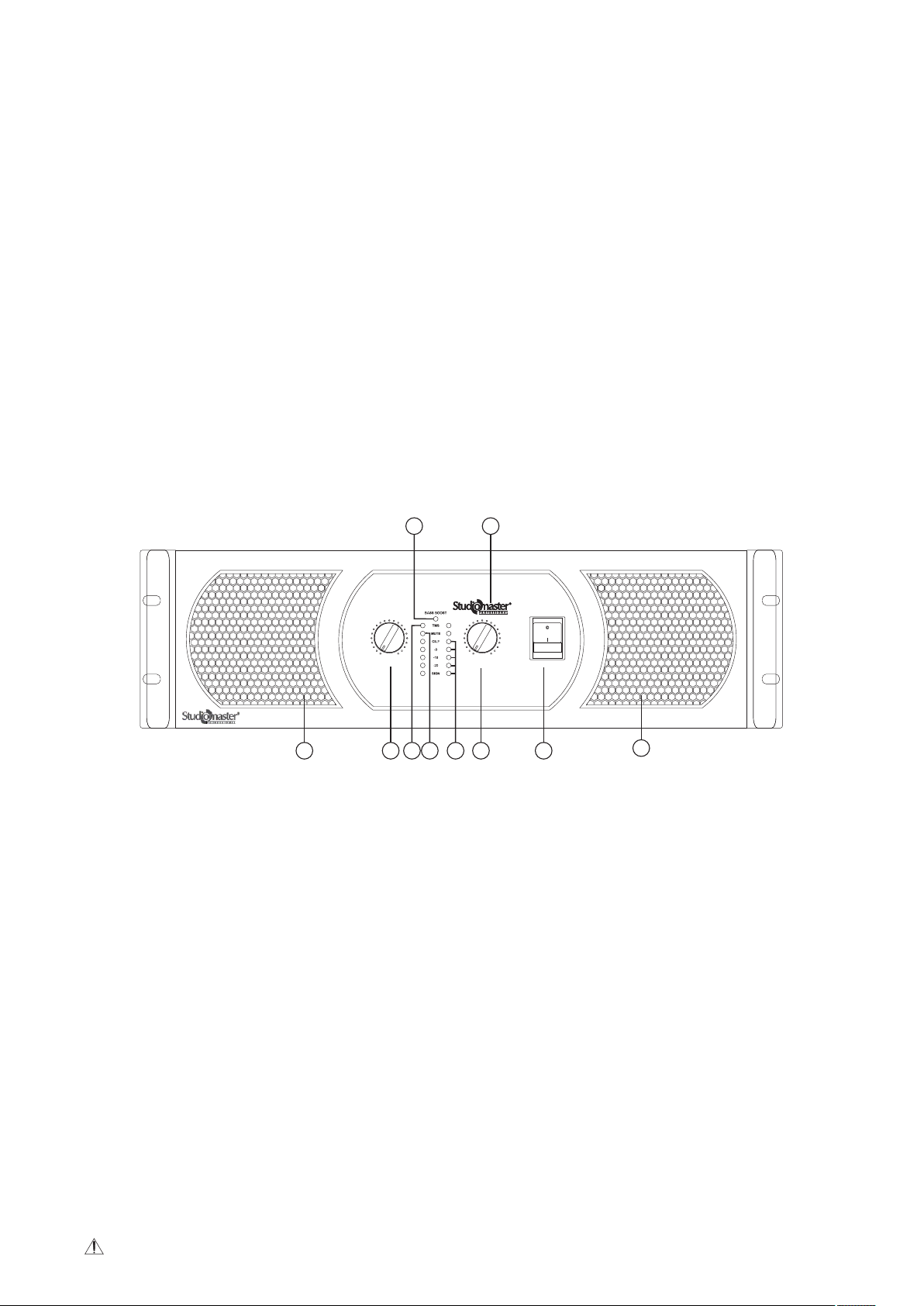
4. Front & Rear Panel Description
Front Panel
7 2
0 10
CH A
8
3 4 5 3 16
0 10
CH B
XPA 40
POWER
8
1 Master Switch
Switches the unit on and off.
2 Power ON Indicator Light
The Studiomaster Professional logo lights up when the amplifier is powered on.
3 Volume Control
This knob is used to adjust and control the volume and output level of the respective channel.
4 TMS (Thermal Management System)
This amplifier features an innovative temperature controlled gain variation technology called the Thermal Management System (TMS).
When the temperature at the heatsink reaches beyond the permissible limit, the TMS circuit intuitively reduces the gain proportionally
without any dropouts. This feature prevents the amplifier from going into thermal protection mode thereby ensuring a smooth and
uninterrupted sonic performance.
5 Mute Indicator
The Yellow LED lights up when the amplifier is in mute mode. This may occur due to the following reasons: switch on delay (3 seconds),
presence of a continuous voltage on the channel output, short circuit, thermal protection of the channel, or thermal protection of the
transformer.
6 Signal & Clip Indicator
These 4-segment Green LED lights show the output level of the amplifier. When the Clip LED turns Red, it means that the signal is
distorting/clipping. Kindly reduce the output level from the mixer or other connected devices to avoid any damages.
7 Bass/Boost Indicator
This Red LED lights up when the Bass/Boost Function is activated or is in use.
8 Air Intake Grill
This intake grill sucks in air to dissipate the heat generated and keep the amplifier cool.
For best results, do not obstruct the grill and clean the air filter whenever necessary.
4
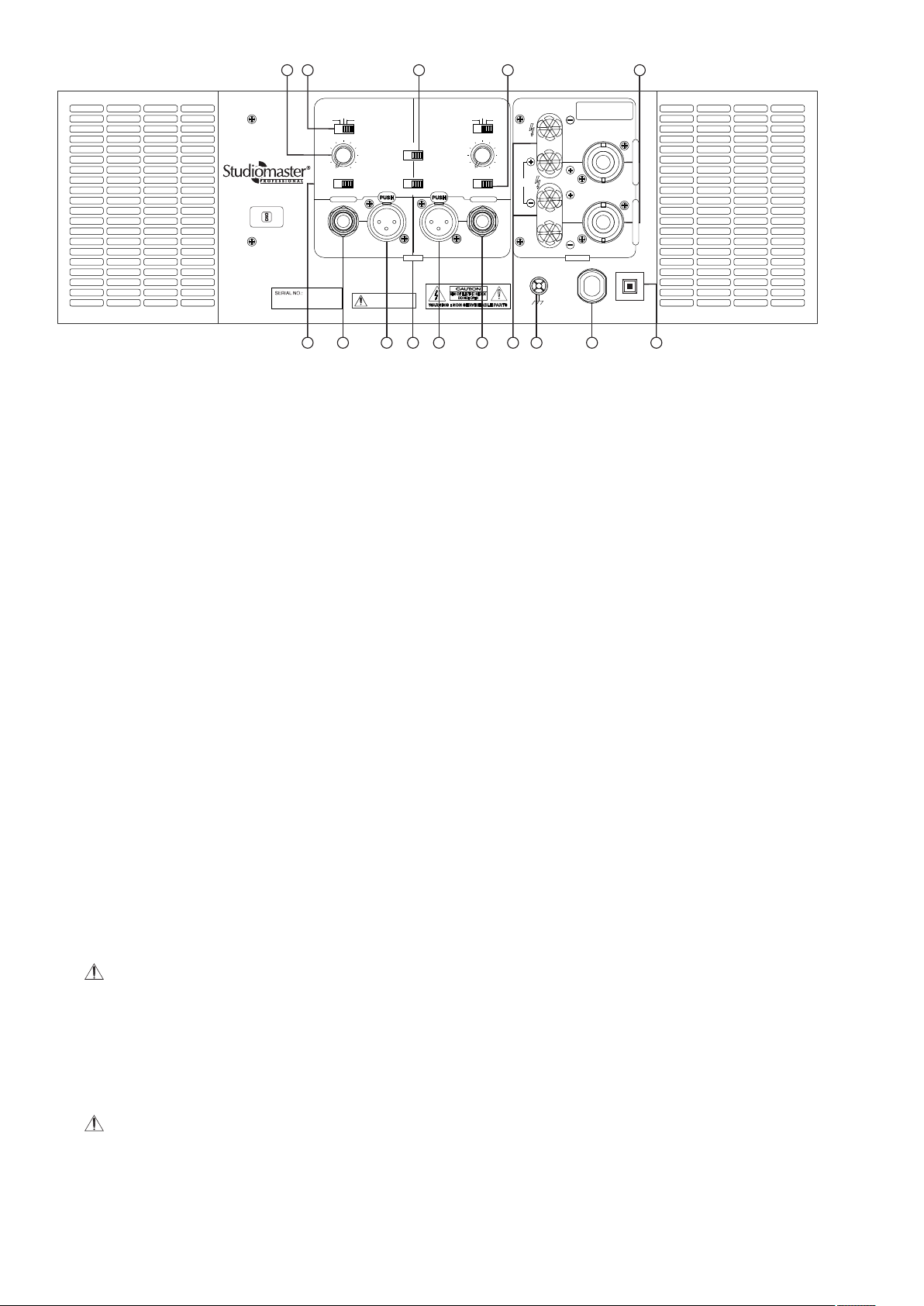
Rear Plate
XPA 40
IS 616/IEC 60065
MADE IN INDIA
R - 71003344
9
SUB
LOW
OFF
CUT
120
63
43
180
FREQUENCY (Hz)
0.775V
SENSITIVITY
CHANNEL B
140
1.2V
WARRANTY VOIDS IF
SERIAL NO. IS MISSING
MONO
BASS/BOOST
OFF
STEREO
INPUT
ON
BRIDGE
For MONO or BRIDGE MODE use Input CHA.
SUB
OFF
120
63
43
FREQUENCY (Hz)
OFF ON
LIMITER
CHANNEL A
121110
Output Connections
ST & MO Mode
+1 = speaker +
GND
-1 = speaker -
OUTPUT
240V~/50Hz
30A, 6300W
LOW
CUT
140
180
BRIDGE
BR Mode CH A only
+1 = speaker +
+2 = speaker -
C
H
A
N
N
E
L
A
C
H
A
N
N
E
L
B
16A
MCB
PUSH TO RESET
4
7
312218
14
65
1 Balanced 6.3 mm Jack Input
This TRS stereo jack connector accepts an input signal (balanced/unbalanced) to drive the respective channel. If the signal is
unbalanced, kindly use a mono (TS) connector.
2 Balanced XLR Input
This XLR connector accepts an input signal (balanced/unbalanced) to drive the respective channel. If the signal is unbalanced, pin 2
can be used for the signal and pin 3 connected to the earth.
3 Output Binding Post
The binding post output is used to pick up the amplified signals individually in the stereo mode & in combination in the bridge mode.
4 Output Speakon Connector
Use this connector for picking up the amplified signal of CH 1 & CH2 and signal for bridged configuration.
5 Power Cable
This cable is used to supply the required power to the unit.
6 Circuit Breaker
The circuit breaker is provided to avoid amplifier failure caused due to a sudden surge or continuous high current supply.
7 Configuration Switch
This three-way switch is used to select between the three operational modes: mono, stereo and bridge.
8 Sensitivity
This switch is used to set the input sensitivity either at 0.775V or at 1.2V depending on the source.
9 Frequency Adjustment Knob
When the filter switch is at SUB or at the LOW CUT position, use this knob to adjust the frequency.
10 Filter Switch
Use this switch to select between the following two filter types.
SUBWOOFER: This is a low-pass filter. The amplifier reproduces frequencies that are lower than the cut-off set by the frequency adjustment knob.
LOW CUT: This is a high-pass filter. You can use this setting to filter out unneeded low or subsonic frequencies.
11 Bass Boost Switch
When you activate this mode, the amplifier adds low-frequency compensation to enhance the speaker's output.
Note: This switch is only effective when the FILTER switch is in the OFF position.
12 Limiter
Use this switch to activate or deactivate the built-in limiter. The limiter prevents distortion at the output level. When the output level
exceeds its maximum, an internal adjustment is made to prevent overloading. It is specially designed to protect the connected
speakers. When the amplifier is used to drive a subwoofer, switch the limiter off for added “punch”.
13 Air Exit Grill
Warm air exits from this grill to dissipate the heat generated and keep the amplifier cool.
For best results, do not obstruct the grill and clean the air filter whenever necessary.
14 External Earth Terminal
Use this for a ground/earthing connection if there are any humming problems.
5
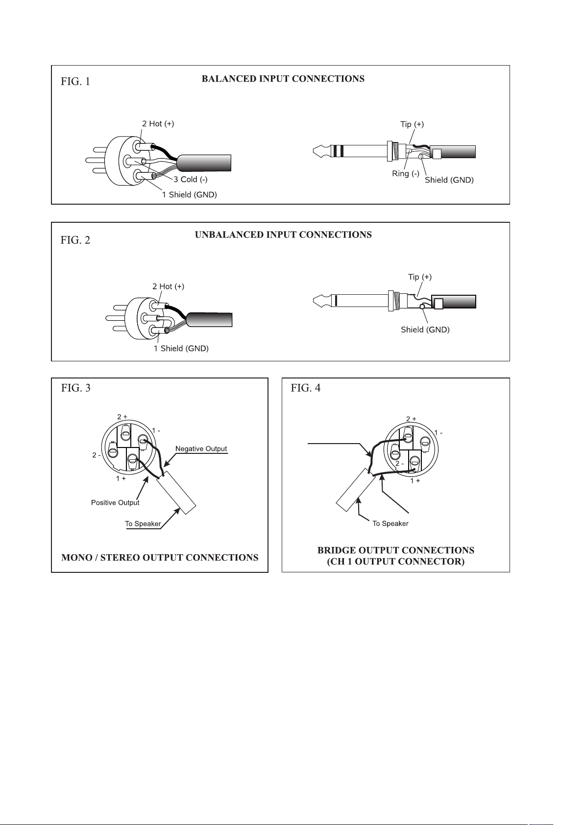
5. Wiring Information.
XLR CONNECTOR STEREO JACK 6.3mm 1/4”
XLR CONNECTOR MONO JACK 6.3mm 1/4”
SPEAKON CONNECTOR
SPEAKON CONNECTOR
Negative Output
Positive Output
6
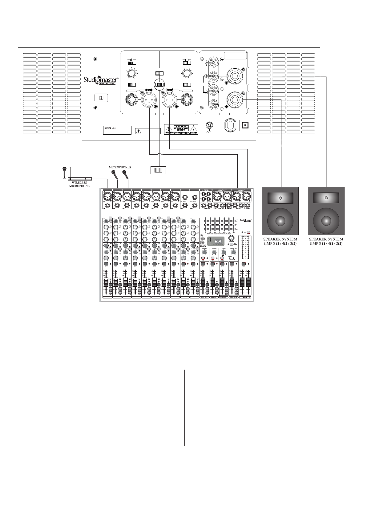
6. System Application.
Stereo Mode Configuration
XPA 40
IS 616/IEC 60065
R - 71003344
MADE IN INDIA
Output Connections
BR Mode CH A only
ST & MO Mode
+1 = speaker +
SUB
LOW
OFF
CUT
120
63
43
180
FREQUENCY (Hz)
0.775V
SENSITIVITY
CHANNEL B
140
1.2V
WARRANTY VOIDS IF
SERIAL NO. IS MISSING
MONO
BASS/BOOST
OFF
STEREO
INPUT
ON
BRIDGE
For MONO or BRIDGE MODE use Input CHA.
SUB
OFF
120
63
43
FREQUENCY (Hz)
OFF ON
LIMITER
CHANNEL A
LOW
CUT
140
180
BRIDGE
GND
-1 = speaker -
OUTPUT
240V~/50Hz
30A, 6300W
+1 = speaker +
+2 = speaker -
16A
MCB
PUSH TO RESET
C
H
A
N
N
E
L
A
C
H
A
N
N
E
L
B
MONO BRIDGE
STEREO
1 2
1 2
3
4 5 6 7 8
3
4 5 6 7 8
9
10
AQ UA 10
9
10
In STEREO mode, both channels A & B are fully independent of each other. The balanced /unbalanced inputs can be connected
either to a stereo signal source or two independent mono signal sources. Each channel can separately drive loudspeaker loads of
8 ohm or 4 ohm or 2 ohm.
Connect the Left & Right outputs of a mixer to channel A
& B inputs of the amplifier respectively. Inputs can be
wired as per fig.1 & 2 (Input Connections for Balanced &
Unbalanced Mode) as mentioned in wiring information on
page no. 6.
Connect a speaker system (8 ohm / 4 ohm / 2 ohm) on the
output terminal of each channel. It is recommended to use
the speakon connectors and wire these as per fig.3 (Output
Connections for Stereo / Mono Mode) as mentioned in
wiring information on page no. 6.
To select STEREO mode, keep the slide switch,
provided at rear panel, in STEREO position.
Adjust the individual volume controls of each channel
on the front panel to obtain the desired output level.
The level indicator LEDs glow to indicate the presence
of signal at the output terminals.
7
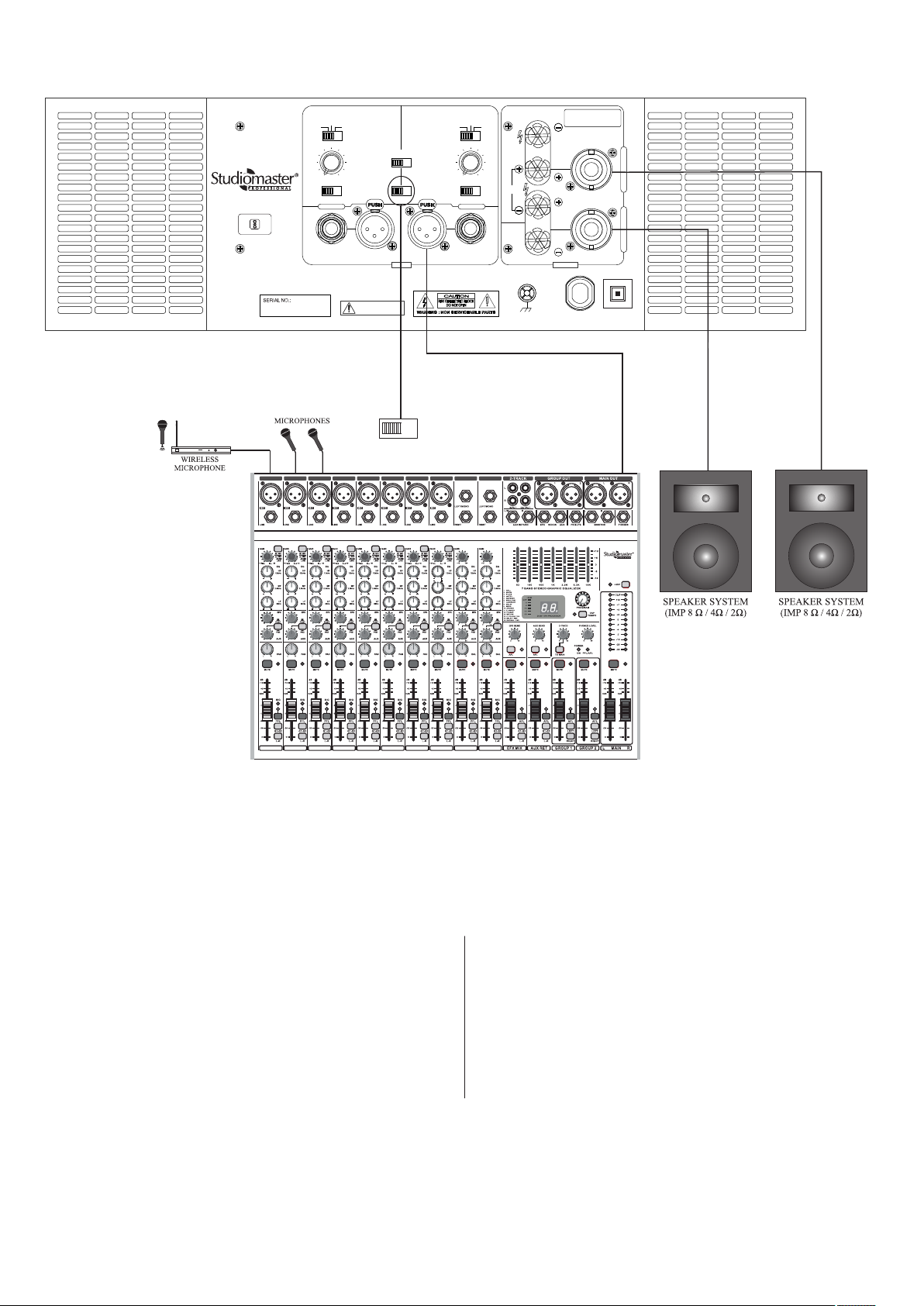
Mono Mode Configuration
XPA 40
IS 616/IEC 60065
R - 71003344
MADE IN INDIA
Output Connections
BR Mode CH A only
ST & MO Mode
+1 = speaker +
SUB
LOW
OFF
CUT
120
63
43
180
FREQUENCY (Hz)
0.775V
SENSITIVITY
CHANNEL B
140
1.2V
WARRANTY VOIDS IF
SERIAL NO. IS MISSING
MONO
BASS/BOOST
OFF
STEREO
INPUT
ON
BRIDGE
For MONO or BRIDGE MODE use Input CHA.
SUB
OFF
120
63
43
FREQUENCY (Hz)
OFF ON
LIMITER
CHANNEL A
LOW
CUT
140
180
BRIDGE
GND
-1 = speaker -
OUTPUT
240V~/50Hz
30A, 6300W
+1 = speaker +
+2 = speaker -
16A
MCB
PUSH TO RESET
C
H
A
N
N
E
L
A
C
H
A
N
N
E
L
B
MONO BRIDGE
STEREO
1 2
1 2
3
4 5 6 7 8
3
4 5 6 7 8
9
10
AQ UA 10
9
10
When operating in MONO mode, the signal source should be connected to the balanced / unbalanced inputs of channel A only.
Both channels provide similar outputs to their respective loudspeakers. Each channel can separately drive loudspeaker loads of
8 ohm or 4 ohm or 2 ohm.
Connect the line output of a mixer to a channel input of
the amplifier. Inputs can be wired as per fig.1 & 2 (Input
Connections for Balanced and Unbalanced Mode) as
mentioned in wiring information on page no. 6.
Connect a speaker system (8 ohm / 4 ohm / 2 ohm) on
the output terminal of each channel. It is recommended
to use the speakon connectors and wire these as per
fig.3 (Output Connections for Stereo / Mono Mode)
as mentioned in wiring information on page no. 6.
To select MONO mode, keep the slide switch, provided at
rear panel, in MONO position.
The desired output levels of both the channels are adjustable
by volume control of both the channels individually.
The level indicator LEDs glow to indicate the presence of
signal at the output terminals.
8

Bridge: Mode Configuration
XPA 40
IS 616/IEC 60065
R - 71003344
MADE IN INDIA
Output Connections
BR Mode CH A only
ST & MO Mode
+1 = speaker +
SUB
LOW
OFF
CUT
120
63
43
180
FREQUENCY (Hz)
0.775V
SENSITIVITY
CHANNEL B
140
1.2V
WARRANTY VOIDS IF
SERIAL NO. IS MISSING
MONO
BASS/BOOST
OFF
STEREO
INPUT
ON
BRIDGE
For MONO or BRIDGE MODE use Input CHA.
SUB
OFF
120
63
43
FREQUENCY (Hz)
OFF ON
LIMITER
CHANNEL A
LOW
CUT
140
180
BRIDGE
GND
-1 = speaker -
OUTPUT
240V~/50Hz
30A, 6300W
+1 = speaker +
+2 = speaker -
16A
MCB
PUSH TO RESET
C
H
A
N
N
E
L
A
C
H
A
N
N
E
L
B
MONO BRIDGE
STEREO
1 2
1 2
3
4 5 6 7 8
3
4 5 6 7 8
9
10
AQ UA 10
9
10
For BRIDGE mode operation, the signal source should be connected to the balanced /unbalanced inputs of channel 1 only. This
mode combines power output of both channels for connecting a single loudspeaker load. The combined loudspeaker load should
not go to below 4 ohm.
Connect the line output of a mixer to a channel A input of
the amplifier. Input can be wired as per fig.1 & 2 (Input
Connections for Balanced and Unbalanced Mode) as
mentioned in wiring information on page no. 6.
Connect a speaker system (8 ohm / 4 ohm) on the
speakon output of channel 1 only. It is recommended
to use the speakon connectors and wire these as per
fig.4 (Output Connections for Bridge Mode) as
mentioned in wiring information on page no. 6.
To select BRIDGE mode, keep the slide switch, provided at
rear panel, in Bridge position.
The desired output levels of both the channels are adjustable
by volume control of channel 1 only.
The level indicator LEDs glow to indicate the presence of
signal at the output terminals.
9
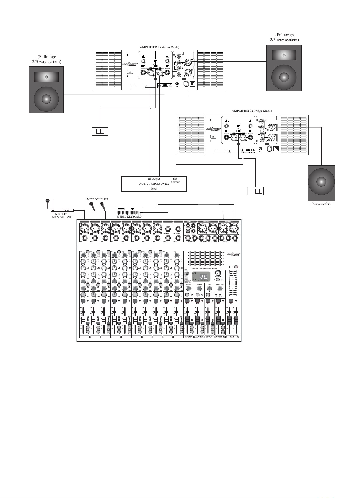
Stereo Mix Plus Subwoofer Configuration
OFF
0.775V
XPA 40
IS 616/IEC 60065
R - 71003344
MADE IN INDIA
MONO BRIDGE
STEREO
63
43
FREQUENCY (Hz)
SENSITIVITY
CHANNEL B
Output Connections
BR Mode CH A only
ST & MO Mode
+1 = speaker +
SUB
LOW
CUT
120
140
180
1.2V
WARRANTY VOIDS IF
SERIAL NO. IS MISSING
MONO
BASS/BOOST
OFF
ON
STEREO
For MONO or BRIDGE MODE use Input CHA.
INPUT
SUB
LOW
OFF
CUT
120
63
140
43
180
FREQUENCY (Hz)
BRIDGE
OFF ON
LIMITER
CHANNEL A
+1 = speaker +
-1 = speaker -
+2 = speaker -
C
H
A
N
N
E
L
OUTPUT
240V~/50Hz
30A, 6300W
MCB
PUSH TO RESET
A
C
H
A
N
N
E
L
B
16A
Output Connections
BR Mode CH A only
ST & MO Mode
+1 = speaker +
+1 = speaker +
-1 = speaker -
+2 = speaker -
C
H
A
N
N
E
L
BRIDGE
A
C
H
A
N
N
E
L
B
OUTPUT
GND
16A
240V~/50Hz
30A, 6300W
MCB
PUSH TO RESET
MADE IN INDIA
XPA 40
IS 616/IEC 60065
R - 71003344
SUB
LOW
OFF
CUT
120
63
140
43
180
FREQUENCY (Hz)
0.775V
1.2V
SENSITIVITY
CHANNEL B
WARRANTY VOIDS IF
SERIAL NO. IS MISSING
OFF
MONO
BASS/BOOST
ON
STEREO
For MONO or BRIDGE MODE use Input CHA.
INPUT
SUB
LOW
OFF
CUT
120
63
140
43
180
FREQUENCY (Hz)
BRIDGE
OFF ON
LIMITER
CHANNEL A
BRIDGE
GND
MONO BRIDGE
STEREO
1 2
1 2
3
4 5 6 7 8
3
4 5 6 7 8
Connect the left & Right outputs of the Audio mixing
console to the respective inputs of the Active Crossover.
Connect the Left & Right High frequency output of the
active crossover to the respective input channels A & B
of amplifier 1.
Inputs can be wired as per fig. 1 & 2 (Input Connections
for Balanced & Unbalanced Mode).
9
10
AQ UA 10
9
10
Feed the Sub output signal of the crossover to channel A
input of amplifier 2. Input can be wired as per fig. 1 & 2
(Input Connections for Balanced & Unbalanced Mode)
One no. of each of high powered subwoofer system can
be connected to the channel A output of amplifier 2.
Output speakon connectors can be wired as per fig. 4
(Output Connections for Bridge Mode).
One no. of full range loudspeaker system can be
connected to each of the channels of amplifier 1.
The output speakon connectors should be wired as per
fig. 3 (Output Connections for Stereo/Mono Mode)
Amplifier 1 will be used in STEREO mode. Keep the
slides switch of amplifier 1 in STEREO position.
Amplifier 2 will be used in bridge mode. Keep the slide
switch of amplifier 2 to BRIDGE position to activate
bridge mode.
Finally adjust the volume control of channel A & B in
amplifier 1 to control the level of their respective position
to get desired power. Also, adjust the volume control of
channel A in amplifier 2 to control the levels of Sub out.
10

Stereo Mode: Cascade Configuration
XPA 40
MADE IN INDIA
XPA 40
MADE IN INDIA
IS 616/IEC 60065
R - 71003344
IS 616/IEC 60065
R - 71003344
Output Connections
BR Mode CH A only
ST & MO Mode
+1 = speaker +
SUB
LOW
OFF
CUT
120
63
140
43
180
FREQUENCY (Hz)
0.775V
1.2V
SENSITIVITY
CHANNEL B
WARRANTY VOIDS IF
SERIAL NO. IS MISSING
BASS/BOOST
OFF
MONO
ON
BRIDGE
STEREO
For MONO or BRIDGE MODE use Input CHA.
INPUT
OFF
63
43
FREQUENCY (Hz)
OFF ON
LIMITER
CHANNEL A
SUB
LOW
CUT
120
140
180
+1 = speaker +
-1 = speaker -
+2 = speaker -
C
H
A
N
N
E
L
BRIDGE
A
C
H
A
N
N
E
L
B
OUTPUT
GND
16A
240V~/50Hz
30A, 6300W
MCB
PUSH TO RESET
MONO BRIDGE
STEREO
1 2
1 2
3
4 5 6 7 8
3
4 5 6 7 8
Connect the left and Right outputs of the Audio mixing
console to the channel A & B (XLR/jack) of amplifier 1.
The XLR and jack inputs of the amplifier are in parallel.
Either ones can be used.
Connect CH A jack input of amplifier 1 to CH A XLR/jack
of amplifier 2. Similarly connect for CH B. Speakers can
be connected to respective output but ensure that resultant
impedance is not less than 2 ohms.
The input can be wired as per fig. 1 & 2 (Input
Connections for Balanced and Unbalanced Mode)
as mentioned in wiring information on page no. 6.
9
10
AQ UA 10
9
10
The speaker connections of amplifier 2 are done in a similar
way as for amplifier 1.
Amplifier 1 & 2 will be used in STEREO mode. Keep the slide
switch of amplifier 1 & 2 in STEREO position.
Adjust the volume controls of channel A & B of both the
amplifiers to control the levels of their respective Speakers.
Finally any adjustments in the total quantity of the sound,
if required, can be made from the audio mixing console.
11
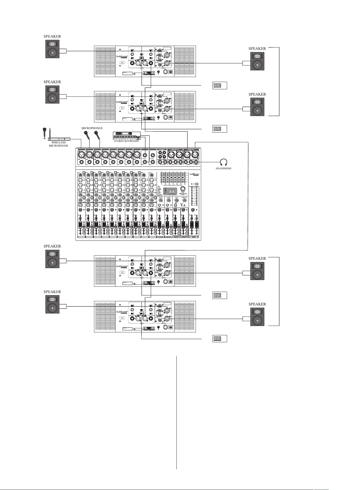
Mono Mode - High Power Dual Channel Configuration
AMPLIFIER 2 (Mono Mode)
AMPLIFIER 1 (Mono Mode)
3
1 2
4 5 6 7 8
MADE IN INDIA
MADE IN INDIA
XPA 40
XPA 40
Output Connections
BR Mode CH A only
ST & MO Mode
+1 = speaker +
SUB
LOW
OFF
63
43
FREQUENCY (Hz)
0.775V
SENSITIVITY
CHANNEL B
IS 616/IEC 60065
R - 71003344
OFF
CUT
120
BASS/BOOST
63
140
OFF
ON
43
180
FREQUENCY (Hz)
MONO
BRIDGE
OFF ON
1.2V
STEREO
CHANNEL A
For MONO or BRIDGE MODE use Input CHA.
INPUT
WARRANTY VOIDS IF
SERIAL NO. IS MISSING
+1 = speaker +
SUB
-1 = speaker -
+2 = speaker -
LOW
CUT
120
140
180
LIMITER
C
H
A
N
N
E
L
A
BRIDGE
C
H
A
N
N
E
L
B
OUTPUT
GND
16A
240V~/50Hz
30A, 6300W
MCB
PUSH TO RESET
LEFT
MONO BRIDGE
Output Connections
BR Mode CH A only
ST & MO Mode
+1 = speaker +
SUB
LOW
OFF
63
43
FREQUENCY (Hz)
0.775V
SENSITIVITY
CHANNEL B
IS 616/IEC 60065
R - 71003344
OFF
CUT
120
BASS/BOOST
63
140
OFF
ON
43
180
FREQUENCY (Hz)
MONO
BRIDGE
OFF ON
1.2V
STEREO
CHANNEL A
For MONO or BRIDGE MODE use Input CHA.
INPUT
WARRANTY VOIDS IF
SERIAL NO. IS MISSING
+1 = speaker +
SUB
-1 = speaker -
+2 = speaker -
LOW
CUT
120
140
180
LIMITER
C
H
A
N
N
E
L
A
BRIDGE
C
H
A
N
N
E
L
B
OUTPUT
GND
16A
240V~/50Hz
30A, 6300W
MCB
PUSH TO RESET
STEREO
MONO BRIDGE
STEREO
9
10
AQ UA 10
BACK
1 2
3
4 5 6 7 8
9
10
AMPLIFIER 3 (Mono Mode)
MADE IN INDIA
XPA 40
SUB
OFF
120
63
43
180
FREQUENCY (Hz)
0.775V
SENSITIVITY
CHANNEL B
IS 616/IEC 60065
R - 71003344
SUB
LOW
CUT
140
1.2V
WARRANTY VOIDS IF
SERIAL NO. IS MISSING
MONO
BASS/BOOST
OFF
STEREO
INPUT
ON
BRIDGE
For MONO or BRIDGE MODE use Input CHA.
OFF
63
FREQUENCY (Hz)
OFF ON
LOW
CUT
120
140
43
180
BRIDGE
LIMITER
CHANNEL A
OUTPUT
GND
240V~/50Hz
30A, 6300W
AMPLIFIER 4 (Mono Mode)
MADE IN INDIA
XPA 40
SUB
OFF
120
63
43
180
FREQUENCY (Hz)
0.775V
SENSITIVITY
CHANNEL B
IS 616/IEC 60065
R - 71003344
SUB
LOW
CUT
140
1.2V
WARRANTY VOIDS IF
SERIAL NO. IS MISSING
MONO
BASS/BOOST
OFF
STEREO
INPUT
ON
BRIDGE
For MONO or BRIDGE MODE use Input CHA.
OFF
63
FREQUENCY (Hz)
OFF ON
LOW
CUT
120
140
43
180
BRIDGE
LIMITER
CHANNEL A
OUTPUT
GND
240V~/50Hz
30A, 6300W
Connect the left line output of the Audio mixing console
to the channel A input (XLR/jack) of amplifier 1. The XLR
& jack inputs of the amplifier are in parallel and either ones
can be used.
Connect the unused channel A input ( jack/XLR) of
amplifier 1 to the channel A input (XLR/jack) of amplifier 2.
The jack & XLR inputs can be wired as per fig. 1 & 2 (Input
Connections for Balanced and Unbalanced Mode) as
mentioned on page no 6.
Output Connections
BR Mode CH A only
ST & MO Mode
+1 = speaker +
+1 = speaker +
-1 = speaker -
+2 = speaker -
C
H
A
N
N
E
L
A
C
H
A
N
N
E
L
B
16A
MCB
PUSH TO RESET
RIGHT
MONO BRIDGE
Output Connections
BR Mode CH A only
ST & MO Mode
+1 = speaker +
+1 = speaker +
-1 = speaker -
+2 = speaker -
C
H
A
N
N
E
L
A
C
H
A
N
N
E
L
B
16A
MCB
PUSH TO RESET
STEREO
MONO BRIDGE
STEREO
BACK
Keep the slide switch of amplifier 1 & 2 in MONO position.
Similarly, connect the Right line output of the Audio mixing
console to the channel A input (XLR/jack) of amplifier 3.
Also connect the unused channel A input (jack/XLR) of
amplifier 3 to the channel A input (XLR/jack) of amplifier 4.
The Right speaker stack’s connections are done in a similar
way as for left speaker stack’s connections. Amplifier 3 & 4
will also be used in MONO mode.
The Left speaker stack compromises of four nos. speaker
systems. Each speaker is individually connected to the four
speaker outputs available from amplifier 1 (channel A & B)
& amplifier 2 (channel A & B). Output speakon connectors
to be wired as per fig. 3 (Output Connections for Stereo/
Mono Mode). Amplifier 1 & 2 will be used in mono mode.
Adjust the volume controls of individual channels of four
amplifier to control the levels of their respective speakers.
Finally any adjustments in the total quality of the sound,
if required, can be made from the audio mixing console.
12
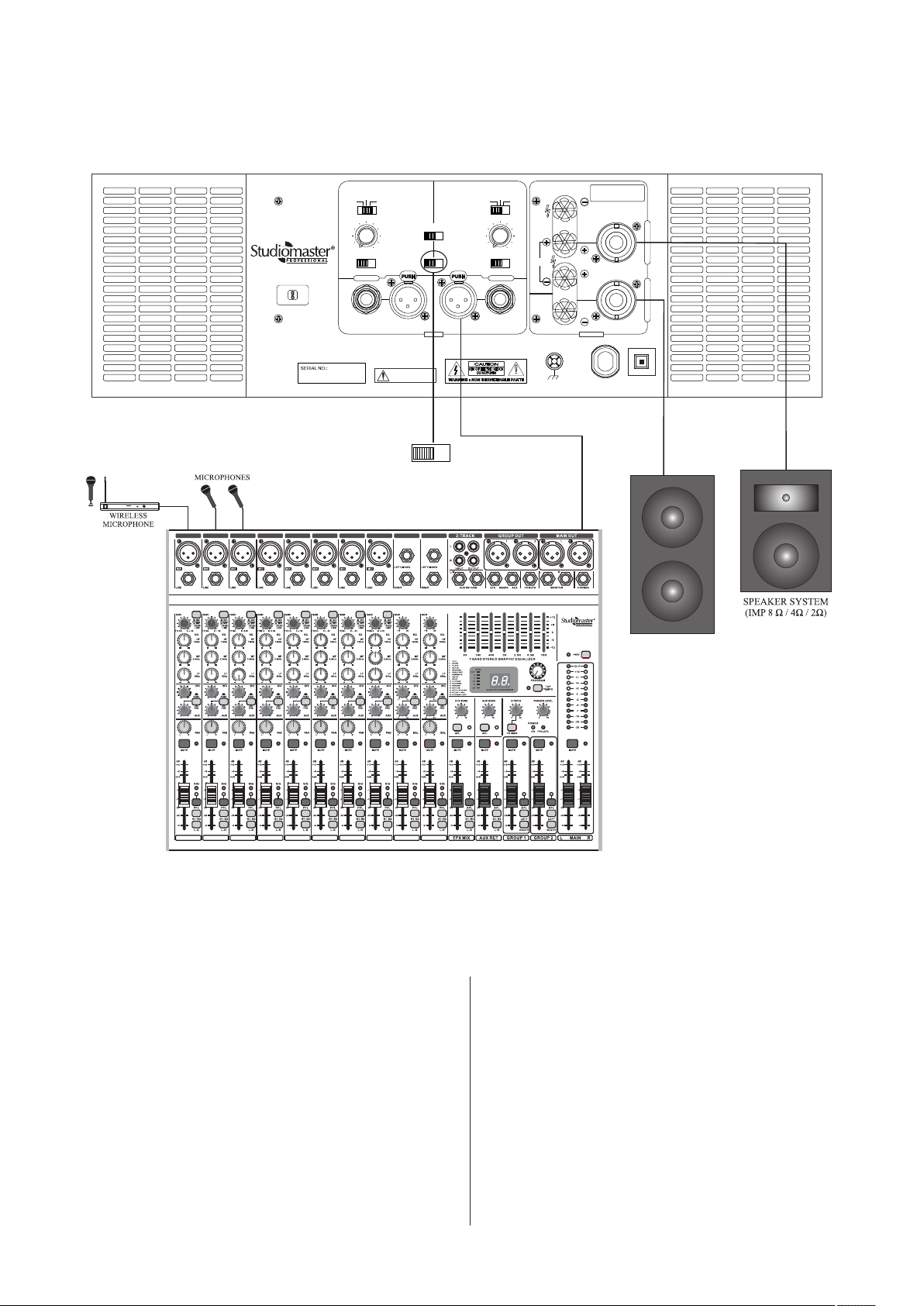
Mono Mode + Subwoofer Configuration
SUB
OFF
120
63
43
FREQUENCY (Hz)
0.775V
XPA 40
MADE IN INDIA
IS 616/IEC 60065
R - 71003344
SENSITIVITY
CHANNEL B
LOW
CUT
BASS/BOOST
140
OFF
MONO
STEREO
INPUT
ON
For MONO or BRIDGE MODE use Input CHA.
180
1.2V
WARRANTY VOIDS IF
SERIAL NO. IS MISSING
MONO BRIDGE
STEREO
BRIDGE
SUB
OFF
120
63
43
FREQUENCY (Hz)
OFF ON
LIMITER
CHANNEL A
Output Connections
BR Mode CH A only
ST & MO Mode
+1 = speaker +
+1 = speaker +
-1 = speaker -
OUTPUT
240V~/50Hz
30A, 6300W
+2 = speaker -
16A
MCB
PUSH TO RESET
C
H
A
N
N
E
L
A
C
H
A
N
N
E
L
B
LOW
CUT
140
180
BRIDGE
GND
1 2
1 2
3
4 5 6 7 8
3
4 5 6 7 8
9
10
AQ UA 10
9
10
SUBWOOFER
Connect the left line output of audio mixing console to the
channel input (XLR Jack) of amplifier. The XLR & Jack inputs
of the amplifier are in parellal and either ones can be used.
The Jack & XLR inputs can be wired as per fig 1 & 2
(input connections for balanced and unbalanced mode) as
mentioned on page no. 6.
connect a speaker system (8 ohm / 4 ohm) on the speakon /
output binding post of each channel.
It is recommended to use the speakon connector and
wire these as per fig 3 (output connection for stereo /
mono mode)
Keep mode selection switch at MONO position.
keep channel 2 sub woofer / low cut switch at MID
position ie. sub-woofer position.
Change frequency knob for sub woofer frequency
as per your choice.
Adjust the individual volume controls of each channel on
the front panel to obtain the desired output level.
The level indicator LEDs glow to indicate the presence
of signal at the output terminals.
13

7. Block Diagram.
BRIDGE MODE
MONO/STEREO
MODE
CHANNEL A OUTPUT
CH A
TMS
CH B
CH A
CH A
MONO/STEREO
GND
BRIDGE
CH B OUTPUT
CH B
MONO/STEREO
GND
MONO/STEREO MODE
CHANNEL B OUTPUT
PSU
CIRCUIT
AMP 1
AMP 2
0-24V
0-23V
VOL. CONTROL
VOL. CONTROL
21V-0-21V
CONTROL CIRCUIT
EMC CIRCUIT
OFF
OFF
AUX
TRANSFORMER
E
CH A
CH B
14
8. Protections & Installations.
Thermal Protection
TMS (Thermal Management System)
This amplifier features an innovative temperature controlled
gain variation technology called the Thermal Management
System (TMS).
When the temperature at the heatsink reaches beyond the
permissible limit, the TMS circuit intuitively reduces the gain
proportionally without any dropouts. This feature prevents the
amplifier from going into thermal protection mode thereby
ensuring a smooth and uninterrupted sonic performance.
Output Devices
Due to excessive heating of output devices, the thermal
protection circuit brings the audio signal to mute state. Onset
of thermal protection circuit is indicated by glowing of Mute
LEDs (yellow) in each channel.
To restore normal operation conditions, it is recommended
to switch off the amplifier and rectify the cause.
Transformer
Due to excessive heating of transformer, the thermal
protection circuit brings the audio signal to mute state. Onset
of thermal protection circuit is indicated by glowing of Mute
LEDs (yellow) in each channel.
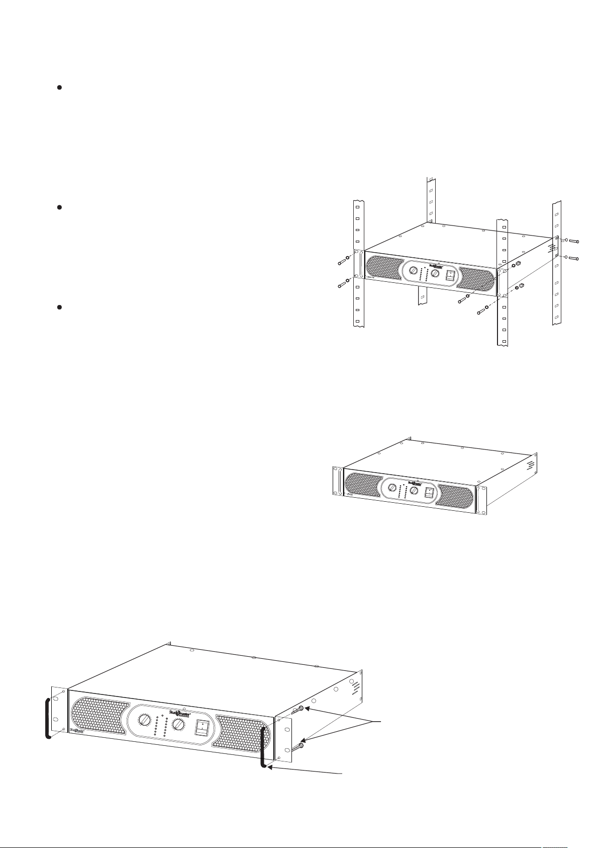
19” Rack Installation
The amplifier is designed for use in a standard 19” rack
with height of 3U units.
In order to provide sufficient support base to the heavy
amplifier, it is essential to use the 19” rack system with side
support mounting also in addition to front screw mounting
as shown in the figure below.
BASS BOOST
TMS
MUTE
CLIP
0
-3dB
10
CH
-10dB
A
0
10
-20dB
CH B
SIG
XPA 40
POWER
To restore normal operation conditions, it is
recommended to switch off the amplifier & rectify the
cause.
DC, RFI Protection
Inbuilt circuitry is provided to protect the loudspeaker from
any offset DC voltages. Also sufficient suppression filters at
primary & secondary power supplies have been inbuilt, to
overcome RF interferences.
Overload / Short Circuit Protection
Protection circuit is provided in both channels for the safety of
output devices in case of overloading or mismatching of
impedances at outputs.
Over Voltage Protection
Built in protection against mains over voltage supply. It is
especially useful while operating amplifier on Genset.
This avoids amplifier failure at higher mains.
Handle Fitting Instruction
Table Top Usage
The ‘U’ handles are helpful in easy portability of the
amplifier for table top usage. Do not keep the set on an
unstable stand or tripod.
BASS BOOST
TMS
MUTE
CLIP
0
-3dB
10
CH A
-10dB
0
10
-20dB
CH B
SIG
XP
POWER
A
40
+
BASS BOOST
TMS
MUTE
CLIP
0
-3dB
10
CH A
-10dB
0
10
-20dB
CH B
SIG
XP
POWER
A 40
Screw M5x10mm
(HRDBN458) 4 Nos.
Handle
(PVCIPC98) 2 Nos.
Note:- 1) Handles to be fitted on both sides as shown in diagram above.
2) Handle (PVCIPC98) 2 nos. & Screw M5x10 (HRDBN458) 4 nos. are included in packing.
15

9. Trouble Shooting:
Key to LED symbols:
Indication
1. Normal operation
BASS
TMS
MUTE
CILP
-3dB
-10dB
-20dB
SIGN
1. Normal operation with TMS LED ON
BASS
TMS
MUTE
CILP
-3dB
-10dB
-20dB
SIGN
1. The amplifier is in normal operation.
1.The amplifier is in normal operation. TMS LED shows gain is controlled due to increase in
heatsink temperature.
GLOWING
BLINKING
Possible Reason
OFF
2. No power to the amplifier
BASS
TMS
MUTE
CILP
-3dB
-10dB
-20dB
SIGN
3. Low output
BASS
TMS
MUTE
CILP
-3dB
-10dB
-20dB
SIGN
1. The amplifier power switch may be off.
2. The amplifier may not be plugged into the power socket.
3. Confirm that the AC outlet works by plugging in another device.
4. If too many amplifiers are used on one outlet, the circuit breaker may trip and shut
off power.
5. An overload in bridge mode may cause tripping of the circuit breaker on the rear panel.
6. An amplifier which keeps shutting off may have a serious internal fault. Turn it off,
remove AC power cord and get the amplifier serviced by a qualified technician.
1. Check if the level of the input signal is too low.
2. Check if the signal source is operating & the input cable is intact.
3. The channel volume control setting is not at desired level.
16

4. No Sound
BASS
TMS
MUTE
CILP
-3dB
-10dB
-20dB
SIGN
5. No Sound
BASS
TMS
MUTE
CILP
-3dB
-10dB
-20dB
SIGN
6. Distorted Sound
BASS
TMS
MUTE
CILP
-3dB
-10dB
-20dB
SIGN
1. The amplifier goes in mute mode due to excessive input signal, speaker impedance
mismatch or output short circuit.
2. Check the speaker impedance & speaker wiring for stray strands or breaks in the
insulation.
3. Reduce the volume control, for desired output.
The amplifier goes in mute mode due to output short circuit, overloading or poor
ventilation resulting into the rise in temperature either of the output devices or the power
transformer. Switch off the amplifier to cool down. Check if the fan is working,
proper ventilation is provided & output connections are as recommended.
To restore normal operation, turn down the volume control, power on the amplifier
once and increase the volume control for desired output.
1. The input signal level may be too high. Turn down the amplifier level controls.
2. Check if the level of the input source. If it is high, reduce the input signal level.
The amplifier should never be operated at a level which causes the Clip LEDs to
illuminate constantly.
8. Hum.
Move cabling and signal sources to identify the problems areas in the system. Cables with faulty shielding are a
frequent entry point from hum. It occurs due to ground loops.
If the humming persists, kindly get in touch with our authorised service personnel.
9. Hiss.
Unplug the amplifier input to confirm whether the hiss is from the source or a device upstream. The erratic or
popping noises indicate an electronic fault in the offending unit.
17

10. Technical Specification:
Model
Output power
Stereo @ THD 0.1%
Bridged
EIA Power @ THD 0.1%
Single channel driven @ THD 0.1%
Frequency Response
THD + N @ rated power single
channel in 4 Ω load
Damping Factor
Signal to Noise Ratio
Crosstalk
Input Sensitivity
Input Impedance
Protection devices
Input Connector
(per channel)
Output Connector
(per channel)
XPA 40
2Ω (2 x 2000W RMS)
4Ω (2 x 1400W RMS)
8Ω (2 x 850W RMS)
4Ω (4000W RMS)
8Ω (2800W RMS)
2Ω (2 x 3000W)
4Ω (2 x 2100W)
8Ω (2 x 1200W)
2Ω (2 x 2400 RMS)
4Ω (2 x 1600 RMS)
8Ω (2 x 950 RMS)
20Hz-20kHz (± 0.5dB)
< 0.5% @ 1kHz
< 0.5% @ 20kHz
> 400 : 1 (@ 8 Ω)
> 90 dB.
>60 dB @ 1kHz
0.775V/1.2V Switchable
20kΩ balanced, 10kΩ unbalanced.
Temperature, DC, RFI, short circuit, Soft-Start, Overload,
over voltage.
XLR, Jack stereo 6.3mm
4 WAY SPEAKON Connector with Binding post.
Cooling
Indicators (per channel)
Power Consumption
Full Power (4Ω, Bridge mode)
Dimensions (W x D x H )
Net Weight
2 variable-speed High CFM Fans
Power On, Bass/Boost, TMS, Mute, Clip & Signal.
6300W
484 x 575 x 133mm
33 kg
18

For Your Records
● Model No..........................................................................................................................................
● Serial No...........................................................................................................................................
● Dealer’s Name..................................................................................................................................
● Dealer’s Phone No....................................Fax No...........................................................................
● Date of Purchase...............................................................................................................................
Note
19

Range of Studiomaster Professional Products.
Wired Microphones
SM 100XLR
TRIO 100
SM 200XLR
TRIO 200
SM 300I
SM 400XLR
SM 450XLR
SM 500XLR
SM 600XLR
SM 650XLR
SM 800C
SM 900C
SBM 10
Flex 3
Flex 4
Wireless Microphones
BR 28 Series
BR 48 Series
ER 11 Series
ER 31 Series
ER 58 Series
TR 47 Series
XR 20 Series
XR 40 Series
XR 80 Series
XR 100 Series
Conference System
Vak 10 System
Vak 10d / Vak 10c
Vak 20
Crossovers
SX-2
SX-321
SX-341
SX-521
Processors
SEQ 152
SEQ 302F
SEQ 312 / SEQ 341
Multi 3 / Multi 6
SFX 8
SPS 8
SDX 4
Phantom 11
Mixers
~ Cub Series
CUB 4
CUB 6
CUB 6U
~ Air Series
AiR 2
AiR 4
AiR 6
AiR 8
AiR 12
AiR 16
AiR 2U
AiR 4U
AiR 6U
AiR 8U
AiR 12U
AiR 16U
Mixers
AiR Pro 18
AiR Pro 24
AiR Pro 28
AiR Pro 36
~ Air X Series
AiR X 10
AiR X 14
AiR X 18
~ AQUA Series
Aqua 6
Aqua 8
Aqua 10
Aqua 14
~ Digital Mixer
D. Mix 20
~ Diamond Club Series
Diamond Club 6.2
Diamond Club 8.2
Diamond Club 8.2 EFX
Diamond Club 12.2
Diamond Club 12.2EFX
Diamond Club 12.2U
Diamond Club 12.2UX
Diamond Club 16.2
Diamond Club 16.2EFX
~ Diamond Supreme Series
Diamond Supreme 12
Diamond Supreme 12U
Diamond Supreme 16U
~ Club 2000 Series
C 142
C 182
~ Platinum Series
Platinum 16Fx
~ Diamond Pro-3 Series
Pro-3 12.3
Pro-3 16.3
~ DJ Mixers
DJX 300
DJX 325
Playmix 300
DJX 825
DJX 925
DJX 975
Amplifiers
~ P - Series
PA 1.5
PA 2.0
PA 3.0
PA 4.5
PA 6.0
PA 7.5
~ DPA Series
DPA 2000
DPA 3200
DPA 4500
DPA 5000
~ DJA Series
DJA 100
DJA 500
DJA 800
DJA 1600
DJA 2500
DJA 3200
DJA 4000
DJA 5000
XJA 2600
~ Arena Series
Arena 20
Arena 30
~ Industrial Amplifier
ARC 120A
ARC 240A
ARC 120UB
ARC 240UB
Speaker Component
~ S-Series
SWF 18120
SWF 18100
SWF 1880
SWF 1560
SMB 1565
SMB 1545
SMB 1530
SMB 1250
SMB 1230
SMB 1220
SHF 0104
SHF 0106
SHF 0210
~ E-Series
EMB 1225
EMB 1530
EMB 1535
~ TITAN Series
TWF 2115
TWF 1815
TWF 1811
TWF 1810
TWF 1580
TMB 1555
TMB 1535
THF 0208
~ FURY Series
F18.120
F15.70
F15.40
F15.50X
F15.40X
F12.30X
Passive Speakers
~ S-Series
S5225
S8018
S8118
S8128
S8028
~ Fire Series
Fire 21/ Fire 51
Fire 51A
Fire 55
* Design and specification are subject to change without notice.
Passive Speakers
~ Fire Series
Fire 57
Fire 82
Fire 84
~ XVP Series
XVP 1225
XVP 1540
XVP 1540M
XVP 1560
XVP 2250
XVP 2550
XVP 2585
XVP 25A2
XVP 25A6
XVP 1808
XVP 1810
XVP 1812
XVP 2820
~ ELAN Series
ELAN 155
ELAN 181
EKS 151
Q 400
Powered Speaker
~ ARIA Series
Aria 8
Aria 12
Aria 15
~ A Series
A 400
A 500
H 400
~ B Series
B 200
B 400
~ OP Series
OP 415
OP 515
~ SUB Series
12SUB
15SUB
Line Array System
FIRE 92
SLA-40 T
SLA-40 Kit
SLA 30
S 9022
Stabilizers
SVC - S1000
SVC - S2000
SVC - S3000
SVC - S5000
SVC - S6000
SVC - S8000
SVC - S10000
SVC - S12000
is a registered trademark of Audioplus in India. © Copyright Audioplus, 2008. All rights reserved. Any unauthorised
reproduction or use of logos, images or design elements is strictly prohibited by law. No part of the compilation may be
reproduced in any manner or translated without written permission.
A1/A2, Giriraj Industrial Estate, Mahakali Caves Road, Andheri (East), Mumbai - 400 093. India
Tel.: 022-42869000 / 001 / Fax: +91-22-26871453 WhatsApp.: +91-8879028079
E info@audioplus-india.com W www.audioplus-india.com / www.studiomasterprofessional.com
LITMAZF8. REV 0.
 Loading...