

Index:
1. Important Notes
2. Important Safety Precautions
3. Introduction
4. Features at a Glance
5. Rear Panel Artwork
6. Configuring & Setting-Up
7. Rigging Instructions
8. Flying Patterns
9. Live Setup
10. Connection Diagrams & Dimension
11. Technical Specifications
SLA 30
Active Compact Line Array System
INSTRUCTION MANUAL
SLA 30

2
1. Important Notes
•
•
•
•
•
Before connecting and using this product, please read this instruction manual carefully.
Be sure to follow all the precautionary instructions in this section, which contain important warnings and or cautions regarding
safety.
The manual is to be considered as integral part of this product & must accompany it when it changes ownership as a reference
for correct installation and use as well as for the safety precautions.
Install in accordance with Studiomaster Professional's instructions and under the supervision of a licensed Professional Engineer
only.
Studiomaster Professional shall not assume any responsibility for the incorrect installation/or use of this product.
Safety symbols and messages described below are used in this manual to prevent bodily injury and property damage which could
result from mishandling. Before operating your product, read this manual first and understand the safety symbols and messages so
you are thoroughly aware of the potential safety hazards.
SAFETY SYMBOL AND MESSAGE CONVENTIONS
1. Make sure all connections have been made correctly.
2. Protect Input cables and interconnection cables from damage; make sure they are positioned in a such way that they can not be
stepped on or crushed by any object.
3. Make sure that no object or liquids can get in to the product as this may cause short circuit.
4. Never attempt to carry out any operations, modifications or repairs that are not expressly mentioned in this manual. Contact your
authorized dealer or qualified personnel if any of the following occur:
The system does not function or works in anomalous way.
The cable has been damaged.
Objects or liquid have got in to unit.
The system has been damaged due to heavy impact or fire.
5. Before placing, installing, rigging, or suspending any speaker product, inspect all hardware, suspension, cabinets, transducers,
brackets and associated equipment for damage.
6. Any missing, corroded, deformed, or non-load rated component could significantly reduce the strength of the installation,
placement or array. Any such condition severely reduces the safety of the installation and should be immediately corrected.
7.
Never exceed the rating of the hardware or equipment.
Avoid installing or mounting the unit in unstable locations, such as on a rickety table or a slanted surface. Doing so may result in
the unit falling down and causing personal injury and/or property damage.
9. Refer all installation work to the dealer from whom the speaker was purchased. Installation for flying requires extensive technical
knowledge and experience. The speaker may fall off if incorrectly installed, resulting in possible personal injury.
10. For Flying be sure to follow the instructions below. Otherwise, the suspension wires or belts may be off or snap and the speaker
may fall off, causing personal injury.
Check to confirm that the suspension wires and belts are strong enough to withstand the speaker load.
The connectors of the suspension wires and belts must be securely linked with those of the speaker.
11. Install the unit only in a location that can structurally support the weight of the unit and the mounting bracket. Doing otherwise
may result in the unit falling down and causing personal injury and/or property damage.
12. Owing to the unit's size and weight, be sure that two or more persons are available to install the unit. Failure to do so could result
in personal injury.
8.
Use only recommended hardware, brackets, joining plates, locking pins etc which are supplied with the unit
for the installation.
•
•
•
•
•
•
2. Important Safety Precautions
Indicates a potentially hazardous situation which, if mishandled,
could result in moderate or minor personal injury, and/or property damage.
Indicates a potentially hazardous situation which, if mishandled,
could result in serious personal injury.

3
1. Do not operate the unit for an extended period of time with the sound distorting. This is an indication of a malfunction, which in turn
can cause heat to generate and result in a fire.
2. Do not stand or sit on, nor hang down from the unit as this may cause it to fall down or drop, resulting in personal injury and/or
property damage.
3. Should the unit emit any strange odours or smoke, remove it from line after having the amplifier switched off.
4. Exposure to high sound levels can cause permanent hearing loss. The acoustic pressure level that leads to hearing loss is different
from person to person and depends on the duration of exposure. To prevent it wear ear plugs or protective earphones.
14. Do not use other methods than specified to mount the bracket. Extreme force is applied to the unit & the unit could fall off, possibly
resulting in personal injuries.
15. Tighten each nut and bolt securely. Ensure that the bracket has no loose joints after installation to prevent accidents that could result
in personal injury.
16. Do not mount the unit in locations exposed to constant vibration. The mounting bracket can be damaged by excessive vibration,
potentially causing the unit to fall, which could result in personal injury.
3. Introduction
Thank you for purchasing the Studiomaster Professional SLA 30 Active Compact Line Array System. To ensure
optimum performance & safety, please follow this instruction manual carefully. Please retain this manual for future
reference. For any complaint, feedback or testimonials please contact our distributor / dealer.
The SLA 30 is a specially designed loudspeaker module designed to form a vertical stack in varying numbers. This
stack is usually flown to provide superior sound coverage in the intended listening areas. Stacked SLA 30 modules
form a line array for constructive summing and increased coupling. Sound dispersion of SLA 30 array has a very
narrow vertical dispersion angle. Therefore sound can be precisely directed where audience is present.
The SLA 30 has a maximum hinge of 10°, variable in steps of 2°. This hinge is enough to provide necessary tilt in
a typical J or spiral array. The SLA 30 is capable of producing peak SPL of 123dB with its Single LF driver & twin
HF drivers. For achieving even sound pressure levels in the audience areas, SLA 30 is provided with a switch for
altering its sensitivity from nominal 0dB to -3dB & +3dB. The SLA 30 has a full frequency response ranging from
85Hz to 19kHz.
Important Concept of Line Array:
In the case of normal loudspeakers, as sound travels, its SPL (Sound Pressure Level) falls by 6dB for every
doubling of distance. In the case of a Line Array the fall in SPL is 3dB for every doubling of distance up to a
certain distance called transition point. Beyond that the fall in SPL is 6dB for every doubling of distance as in
the case of normal loudspeakers.
The transition point is dependent on the length of the line array. Longer the array, further away is the transition
point. Therefore if near equal SPL is desired spanning the front row to the last row, it is recommended to have
more numbers of SLA 30 enclosures stacked vertically in spiral formation.
SLA 30: The SLA30 incorporates 1 x 8” Woofer and
2 x 1.5” HF with state of the art Waveguide horn, all
comprised into a sleek & lightweight enclosure. This
Array module has a horizontal coverage angle of 100°
& vertical Coverage angle of 10°.
SLA 30 System Consists of:
8”, 2 Way 250 Watts @ 8 , Active Line Array ModuleΩ
4
About Waveguides:
Sound Waves in open space propagate in all directions, this way they lose their
power significantly. In order to counter this problem the SLA-30 incorporates
waveguide driver to ensure maximum control on power & dispersion. This ensures
pure performance and negates the possibilities of phase cancellations.
SLA 30 Kit: The SLA 30 Kit is set of essential
hardware required for rigging & flying this line array
system. It consist of ultra durable Flybars / Array
Frames & Quick Release Pins (Push-Pull Bullets). This
kit makes flying the SLA 30 Series a very easy.
SLA 30 KIT: Fly Bars & Quick Release Pins.
4. Features at a Glance
•
•
•
•
•
•
•
•
•
•
The SLA30 is a powered, two-way, full-range line array speaker system.
It is intended for small to mid size venues.
High performance single 8” LF & two 1.5" HF transducers.
In built Limiter.
Gain control. (-15dB to +6dB)
HF level attenuation switch for adjusting tonal balance for different system configurations.
Fast, integral rigging system.
Coverage Pattern: H100 degree x V10degree nominal, single unit.
High grade & durable Plastic cabinet design.
Easy carry handles & heavy duty protective steel grille.
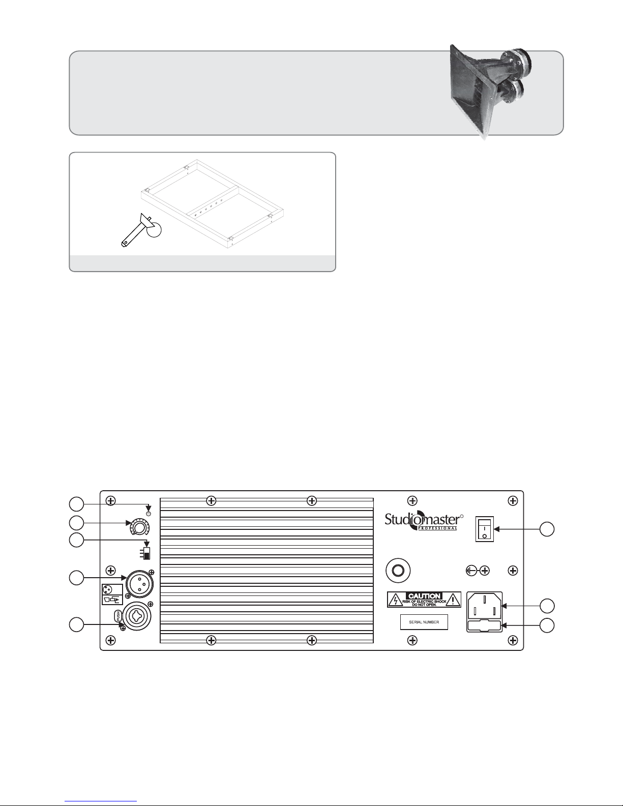
5. Rear Panel Artwork:
1. Balanced input that can be used for connecting an audio source with high level signal output
(e.g. preamplifier, mixer, cassette recorder, CD player, musical instrument, etc.).
Audio Input (Balanced Input):
2. Audio output can be used to send Audio signal to other amplifier speakers, recorders or supplementary
amplifiers or to loop other SLA 30.
Audio Output:
3. HF can be boosted by +3dB or can be cut by -3dB for improved performance.HF Selection Switch:
The -3 dB position will typically be used for the speaker(s) in an array that are covering the nearest listening area.
The +3 dB position will be used for the speaker(s) covering the more distant areas; or to compensate for the low-frequency buildup resulting from mutual coupling of multiple woofers in an array.
240V~ 50Hz, 450W MAX
T2.5A/250V~
ON
POWER
OFF
+6
-15
GAIN
HFATTENUATION
AUDIO INPUT AUDIO OUTPUT
ON - LIMITER
-3dB
+3dB
0dB
Made in India
SLA 30
ACTIVE LINE ARRAYSPEAKER SYSTEM
R
1
6
7
8
2
3
4
5
2
3
1
2
3
1
3=COLD
2=HOT
1=GND

5
HORIZONTAL BEAM
100°
VERTICAL BEAM
10°
4. This knob is used for adjusting the gain (-15dB to +6dB) of the amplifier.Level:
5. The “LIMITER-PROTECTION” indicator light comes on red during start (for a
few seconds) and when the internal audio limiter engages. This avoids the amplifier's distortion and protects the loudspeakers
against overloads.
“LIMITER-PROTECTION” INDICATOR LIGHT:
6. Used for switching the unit on and off.POWER SWITCH:
7. Used for connecting the power cable supplied with the speaker.POWER CABLE SOCKET “MAINS:
8. Mains fuse housing.FUSE CARRIER “FUSE”:
SLA 30 disperses sound as a line source with a vertical beam angle of 10° & horizontal beam angle of 100°. A very
simplistic depiction of this is shown below.
6. Configuring & Setting-Up
SLA 30 enclosures can be flown or ground stacked. For small venues or temporary/rental installations where flying
SLA 30 may not be possible, these can be ground stacked on top of its sub-woofer.
When ground stacked, the SLA 30 enclosures are generally kept straight i.e., all enclosures have 0° tilt without any
splay. Two to four SLA 30 enclosures may be adequate for small venues. A pair (in Left & Right placement) of this set-up
i.e., two to four SLA 30 with one Studiomaster Profesional subwoofer (Combine of SLA 30 power requirement) will
provide very even coverage and used for stereo reproduction of program as well.
As a thumb rule for every four nos. of SLA 30 one S 8018 subwoofer should be employed. When multiple sub-woofers
are used it is better to stack these together for coherent lows. The location of the sub-woofers should be beneath the
stage and centrally positioned.
When SLA 30 enclosures are flown, it is possible to configure these in any one of the following
formation:
Straight Array: In this type all enclosures have 0° tilt. ll modules are arrayed
vertically without any downward tilt. This formation gives a narrow long throw
beam. Such an array will not find deployment in a practical setup because of its
very narrow coverage in vertical plane.
A

6
Spiral or Progressive Array: Unlike a J-Array, spiral or progressive array is a
continuous curve. The upper portion of the array is nearly straight but then
increases in curvature towards the bottom. Most small and mid-sized venues get
covered very well with this type of array formation and we recommend this
formation when installing four to eight SLA 30. This would be the situation with
majority of the installers of SLA 30. With this configuration one can expect very
uniform coverage over the entire audience area. In a spiral array the angle
between successive enclosures changes by a predetermined incremental angle.
SLA-30 has provision for 0°-2°-4°-6°-8°-10° tilt angles.
J-Array: This is a combination of straight and curved arrays. In the real world
Line Arrays are almost always used as curved vertical arrays. A large venue may
consist of a dozen enclosures, with top two to four enclosures straight with 0°
vertical splay, aimed at the farthest seats. As we move down the array, the angle
between adjacent enclosures increases until at the bottom there are one or two
modules aimed almost straight down to cover the front seating area. Therefore
a J-Array has upper portion of the array as straight & then increases in curvature
toward the bottom giving the array the shape of letter J.
Curved Array: In this type, the enclosures are configured as an arc of a circle.
The upper enclosures radiate sound upwards toward the ceiling and the lower
enclosures have a wide lower fill. Such an array has the widest possible
coverage in the vertical plane and is not suitable for long throw requirement.
This configuration is suitable for small venues and if installed indoors, the venue
should have acoustic treatment with highly absorbent ceiling.
Therefore the incremental angle of 2° will yield 0°, 2°, 6°, 12°, 20°, 30°,40°, 50° aiming angles relative to the horizontal
when eight SLA 30 enclosures are flown. The topmost module has 0° tilt and lowest (eighth) has 50° tilt relative to
horizontal.
Powering of topmost enclosure is at full power & subsequent ones are progressively turned
down a little. This way a reasonably even coverage with almost equal SPL in the front seating
area & farthest seating area is achievable. SLA 30 has a switch for providing HF attenuation
of -3dB, 0dB and +3dB. This feature can be utilized during equalization of the frequency
response. A reasonably even frequency response in the entire listening area is also aided by
the wave-guide loaded HF drivers of SLA 30.
Splay / Tilt Angle: This set of angled grooves can be used to tilt the modules in perspective
to the other stacked modules, in order to form the numerous flying configurations.
10°
8°
6°
4°
2°
0°
-3dB
0dB
+3dB
7
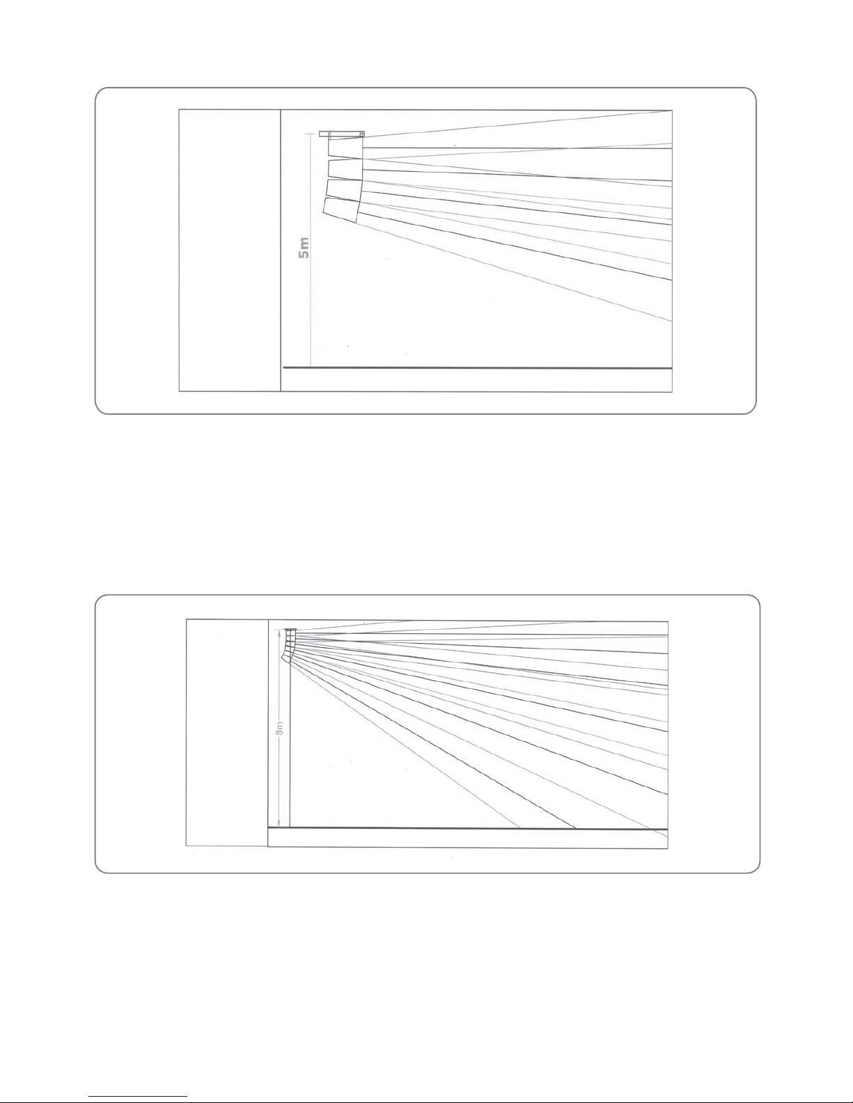
Array flown at a height of 5m (16.5’).
Array flown at height of 6m (20’).
Area of even coverage: 13m (40’) to 55m (80’).
Area of even coverage: 16.5m (55’) to 66m (215’).
For compensating the lower SPL in the sound shadow area between the suspension point of line
array and 13m from it, front fill speakers have to be employed.
Array flown at a height of 5m (16.5’).
Array flown at height of 6m (20’).
Four SLA 30 Array
SPLAY HOLE
1. SLA 30 0°
2. SLA 30 2°
3. SLA 30 4°
4. SLA 30 6°
TILT ANGLE
1. SLA 30 0°
2. SLA 30 2°
3. SLA 30 6°
4. SLA 30 12°
Array flown at a height of 6m (20’).
Array flown at a height of 8m (26’).
Area of even coverage: 6.5m (22’) to 66m (220’).
Area of even coverage: 9.5m (30’) to 90m (300’).
Front fill speakers will be required for compensating the lower SPL in the front audience area.
Array flown at a height of 6m (20’).
Array flown at a height of 8m (26’).
Six SLA 30 Array
SPLAY HOLE
1. SLA 30 0°
2. SLA 30 2°
3. SLA 30 4°
4. SLA 30 6°
5. SLA 30 8°
6. SLA 30 10°
TILT ANGLE
1. SLA 30 0°
2. SLA 30 2°
3. SLA 30 6°
4. SLA 30 12°
5. SLA 30 20°
6. SLA 30 30°

8
7. Rigging Instructions
• The SLA 30 can be rigged using the SLA 30 KIT, as set of essential hardware required for rigging & flying this line
array system. It consists of ultra durable Flybars / Array Frames & Quick Release Pins (Push - Pull Bullets).
Array flown at a height of 6m (20’).
Array flown at a height of 8m (26’).
Area of even coverage: 3m(10’) to 66m (220’)
Area of even coverage: 4m (13’) to 90m (300’)
Flying eight SLA 30 offers no advantage in long distance coverage, but no front fill speakers will be needed as the
lowest SLA 30 with a steep downward tilt covers the front area.
Array flown at a height of 6m (20’).
Array flown at a height of 8m (26’).
Eight SLA 30 Array
TILT ANGLE
1. SLA 30 0°
2. SLA 30 2°
3. SLA 30 6°
4. SLA 30 12°
5. SLA 30 20°
6. SLA 30 30°
7. SLA 30 40°
8. SLA 30 50°
SPLAY HOLE
1. SLA 30 0°
2. SLA 30 2°
3. SLA 30 4°
4. SLA 30 6°
5. SLA 30 8°
6. SLA 30 10°
7. SLA 30 10°
8. SLA 30 10°
SLA 30 Kit
Flybars / Array Frames
Quick Release Pins (Push-Pull Bullets)
• SLA 30 should always be flown with the flybar of Studiomaster Professional SLA 30 Kit. It will ensure the accuracy
and safety of the rigging.

9
• The suspension point should be five to ten feet away from the active area of the stage to minimize feedback.
• Always consult the venue architect or maintenance personnel before flying the array especially in a fixed installation.
• Make sure the speaker is mounted on a stable and sturdy surface/ceiling/wall in case the system is used in a fixed
installation.
• Please secure the flybar with an additional safety chain, especially when the modules are suspended with a
single motor.
•
Note: Studiomaster Professional is not liable for any accident caused due to negligence of the safety instructions,
improper usage, use of inferior quality trusses, chain pulley systems, other flying accessories & mounting on
surfaces which are not strong enough to support the weight of the speakers.
• The ideal height at which the frame should be flown is between 5m to 8m. In auditoriums & churches, a single line
array comprising of 4 to 6 SLA 30 modules should be adequate. This array is normally flown in the centre of the
auditorium or church above the stage proscenium in the vertical plane at the edge of stage towards the audience.
4. Multiple flown arrays
This configuration is to provide side fill for audience spread
out widely on either side of the stage.
3. Left/ Centre/ Right flown arrays
This flying configuration may be needed when the stage is
very wide and centre fill is required for providing even
coverage.
2. Left/ Right flown arrays
This flying configuration is suitable for outdoor venues where wider
horizontal coverage is required. The arrays are usually flown on each
end of the stage.
8. Flying Patterns
1. Centrally flown single array
A centrally flown single array is suitable for indoor installation
where the room is not very wide. SLA 30 has a wide horizontal
dispersion and will be able to evenly disperse sound in rooms
with a width of within 25m.
Left/ Center/Right Positioning
STAGE
Left/ Right Positioning
STAGE
Multiple Array Positioning
STAGE
Center Positioning
STAGE
• It is recommended to employ a chain-pulley system for flying the array with a chain length so that the array can
descend to a level where it can be adjusted for curve articulation and sensitivity setting while standing. The chain
block is to be suspended on the trussing limb above the false ceiling. A 0.5 ton chain-pulley system can be
employed for flying up to 15 SLA 30 modules provided the trussing limb can take the weight.

240V~ 50Hz,450W MAX
T2.5A/250V~
ON
POWER
OFF
+6
-15
GAIN
HFATTENUATION
AUDIO INPUT AUDIO OUTPUT
ON - LIMITER
-3dB
+3dB
0dB
Made in India
SLA 30
ACTIVE LINEARRAYSPEAKER SYSTEM
R
2
3
1
2
3
1
3=COLD
2=HOT
1=GND
240V~ 50Hz,450W MAX
T2.5A/250V~
ON
POWER
OFF
+6
-15
GAIN
HFATTENUATION
AUDIO INPUT AUDIO OUTPUT
ON - LIMITER
-3dB
+3dB
0dB
Made in India
SLA 30
ACTIVE LINEARRAYSPEAKER SYSTEM
R
2
3
1
2
3
1
3=COLD
2=HOT
1=GND
240V~ 50Hz,450W MAX
T2.5A/250V~
ON
POWER
OFF
+6
-15
GAIN
HFATTENUATION
AUDIO INPUT AUDIO OUTPUT
ON - LIMITER
-3dB
+3dB
0dB
Made in India
SLA 30
ACTIVE LINEARRAYSPEAKER SYSTEM
R
2
3
1
2
3
1
3=COLD
2=HOT
1=GND
240V~ 50Hz,450W MAX
T2.5A/250V~
ON
POWER
OFF
+6
-15
GAIN
HFATTENUATION
AUDIO INPUT AUDIO OUTPUT
ON - LIMITER
-3dB
+3dB
0dB
Made in India
SLA 30
ACTIVE LINEARRAYSPEAKER SYSTEM
R
2
3
1
2
3
1
3=COLD
2=HOT
1=GND
240V~ 50Hz,450W MAX
T2.5A/250V~
ON
POWER
OFF
+6
-15
GAIN
HFATTENUATION
AUDIO INPUT AUDIO OUTPUT
ON - LIMITER
-3dB
+3dB
0dB
Made in India
SLA 30
ACTIVE LINEARRAYSPEAKER SYSTEM
R
2
3
1
2
3
1
3=COLD
2=HOT
1=GND
240V~ 50Hz,450W MAX
T2.5A/250V~
ON
POWER
OFF
+6
-15
GAIN
HFATTENUATION
AUDIO INPUT AUDIO OUTPUT
ON - LIMITER
-3dB
+3dB
0dB
Made in India
SLA 30
ACTIVE LINEARRAYSPEAKER SYSTEM
R
2
3
1
2
3
1
3=COLD
2=HOT
1=GND
240V~ 50Hz,450W MAX
T2.5A/250V~
ON
POWER
OFF
+6
-15
GAIN
HFATTENUATION
AUDIO INPUT AUDIO OUTPUT
ON - LIMITER
-3dB
+3dB
0dB
Made in India
SLA 30
ACTIVE LINEARRAYSPEAKER SYSTEM
R
2
3
1
2
3
1
3=COLD
2=HOT
1=GND
240V~ 50Hz,450W MAX
T2.5A/250V~
ON
POWER
OFF
+6
-15
GAIN
HFATTENUATION
AUDIO INPUT AUDIO OUTPUT
ON - LIMITER
-3dB
+3dB
0dB
Made in India
SLA 30
ACTIVE LINEARRAYSPEAKER SYSTEM
R
2
3
1
2
3
1
3=COLD
2=HOT
1=GND
10
9. Live Setup
10
8
GAIN
1
60dB
30
20
40
-
HF
12kHz
+
-+
MF
350 +
450 5k
-+
LF
60Hz
010
010
010
010
LR
EFX
AUX1
AUX2
MONO
PAN
PEAK
LISTEN
L-R
GROUP
+10
+5
0dB
-5
-10
-20
8
1
10
8
GAIN
2
60dB
30
20
40
-
HF
12kHz
+
-+
MF
350 +
450 5k
-+
LF
60Hz
010
010
010
010
LR
EFX
AUX1
AUX2
MONO
PAN
PEAK
LISTEN
L-R
GROUP
+10
+5
0dB
-5
-10
-20
8
2
10
8
GAIN
3
60dB
30
20
40
-
HF
12kHz
+
-+
MF
350 +
450 5k
-+
LF
60Hz
010
010
010
010
LR
EFX
AUX1
AUX2
MONO
PAN
PEAK
LISTEN
L-R
GROUP
+10
+5
0dB
-5
-10
-20
8
3
10
8
GAIN
4
60dB
30
20
40
-
HF
12kHz
+
-+
MF
350 +
450 5k
-+
LF
60Hz
010
010
010
010
LR
EFX
AUX1
AUX2
MONO
PAN
PEAK
LISTEN
L-R
GROUP
+10
+5
0dB
-5
-10
-20
8
4
10
8
GAIN
5
60dB
30
20
40
-
HF
12kHz
+
-+
MF
350 +
450 5k
-+
LF
60Hz
010
010
010
010
LR
EFX
AUX1
AUX2
MONO
PAN
PEAK
LISTEN
L-R
GROUP
+10
+5
0dB
-5
-10
-20
8
5
10
8
GAIN
6
60dB
30
20
40
-
HF
12kHz
+
-+
MF
350 +
450 5k
-+
LF
60Hz
010
010
010
010
LR
EFX
AUX1
AUX2
MONO
PAN
PEAK
LISTEN
L-R
GROUP
+10
+5
0dB
-5
-10
-20
8
6
10
8
GAIN
7
60dB
30
20
40
-
HF
12kHz
+
-+
MF
350 +
450 5k
-+
LF
60Hz
010
010
010
010
LR
EFX
AUX1
AUX2
MONO
PAN
PEAK
LISTEN
L-R
GROUP
+10
+5
0dB
-5
-10
-20
8
7
10
8
GAIN
8
60dB
30
20
40
-
HF
12kHz
+
-+
MF
350 +
450 5k
-+
LF
60Hz
010
010
010
010
LR
EFX
AUX1
AUX2
MONO
PAN
PEAK
LISTEN
L-R
GROUP
+10
+5
0dB
-5
-10
-20
8
8
10
8
GAIN
9
60dB
30
20
40
-
HF
12kHz
+
-+
MF
350 +
450 5k
-+
LF
60Hz
010
010
010
010
LR
EFX
AUX1
AUX2
MONO
PAN
PEAK
LISTEN
L-R
GROUP
+10
+5
0dB
-5
-10
-20
8
9
10
8
GAIN
10
60dB
30
20
40
-
HF
12kHz
+
-+
MF
350 +
450 5k
-+
LF
60Hz
010
010
010
010
LR
EFX
AUX1
AUX2
MONO
PAN
PEAK
LISTEN
L-R
GROUP
+10
+5
0dB
-5
-10
-20
8
10
10
8
GAIN
11
60dB
30
20
40
-
HF
12kHz
+
-+
MF
350 +
450 5k
-+
LF
60Hz
010
010
010
010
LR
EFX
AUX1
AUX2
MONO
PAN
PEAK
LISTEN
L-R
GROUP
+10
+5
0dB
-5
-10
-20
8
11
10
8
GAIN
12
60dB
30
20
40
-
HF
12kHz
+
-+
MF
350 +
450 5k
-+
LF
60Hz
010
010
010
010
LR
EFX
AUX1
AUX2
MONO
PAN
PEAK
LISTEN
L-R
GROUP
+10
+5
0dB
-5
-10
-20
8
12
10
8
GAIN
13/14
60dB
30
20
40
-
HF
12kHz
+
-+
MF
350 +
450 5k
-+
LF
60Hz
010
010
010
010
LR
EFX
AUX1
AUX2
MONO
PAN
PEAK
LISTEN
L-R
GROUP
+10
+5
0dB
-5
-10
-20
8
13/14
10
8
GAIN
15/16
60dB
30
20
40
-
HF
12kHz
+
-+
MF
350 +
450 5k
-+
LF
60Hz
010
010
010
010
LR
EFX
AUX1
AUX2
MONO
PAN
PEAK
LISTEN
L-R
GROUP
+10
+5
0dB
-5
-10
-20
8
15/16
10
8
GAIN
17/18
60dB
30
20
40
-
HF
12kHz
+
-+
MF
350 +
450 5k
-+
LF
60Hz
010
010
010
010
LR
EFX
AUX1
AUX2
MONO
PAN
PEAK
LISTEN
L-R
GROUP
+10
+5
0dB
-5
-10
-20
8
17/18
10
8
8
8
8
8
8
GAIN
19/20
60dB
30
20
40
-
HF
12kHz
+
-+
MF
350 +
450 5k
-+
LF
60Hz
010
010
010
010
LR
EFX
AUX1
AUX2
MONO
PAN
PEAK
LISTEN
L-R
GROUP
+10 +10 +10 +10+10
+5 +5 +5 +5+5
0dB 0dB 0dB 0dB0dB
-5 -5 -5 -5-5
-10 -10 -10 -10-10
-20 -20 -20 -20-20
8
8
8
8
8
19/20 GROUP MONO LEFTEFX RIGHT
LEFT/
MONO
LEFT/
MONO
LEFT/
MONO
LEFT/
MONO
RIGHT RIGHT RIGHT RIGHT
PLATINUM 16Fx
28 input mixer
PHONE
010
AUX1/
MUTE
DELAY
MEN1MEN2MEN3MEN
4
PEAKONWARM
BRIGHT
ON
EFX B EFX EQ REGEN
EFX TO MON
MAX
MIN
MAX
MIN
PEAK
+8
+6
+4
+2
0dBu
-3
-6
-9
-12
-20
LEFT
L-R
LISREN
SPLIT
RIGHT
MON
STAND BY
+12
9
6
-12
9
3
L-R 0dB
3
6
+12
9
6
-12
9
3
0dB LEFT
3
6
+12
9
6
-12
9
3
MON 0dB
3
6
+12
9
6
-12
9
3
0dB RIGHT
3
6
DATAENTRY
EFX TYPE
METER/PHONES
SELECT
L-R
MON
GRAPHIC
ASSIGN 2
L-R
MON
STEREO
AUX1
INPUT
TO MON
LEVEL
010
L-R
GROUP
48V PHANTOM
POWER
PLAYBACK
RIGHT
LEFT/
MONO
STEREO
AUX1 INPUT
RECORD
LR
data FEX
32bit DIGITAL
PROCESSOR
INTELLIGENT USER INTERFACE
GRAPHIC
ASSIGN1
8.8.8.
DISPLAY
EFFECT TYPE
DELAY
100msec, -3.1 sec. 100 msec.-450 msec. 20 msec. 95 msec. 250 msec. 600msec.
59-63 64-74 75-83 84-92
REVERSE MULTI TAPDELAY SINGLE SHORT SINGLE MEDIUM
DISPLAY
EFFECT TYPE
DELAY
100 msec. -600 msec.
93-110 111-114 129-147
REGEN (20% & 40%F.D)
PANNING PITCH SHIFT
115-119 120-123 124-128
PHASER CHORUS FLANGER
DISPLAY
EFFECT TYPE
DELAY
400msec, 3.1 sec. 500msec, 4.2 sec. 1.0 sec. -10.0 sec. 10 0msec. -450 msec.
1.9 19-27 37-45 55-5810-1B 28-36 46-54
PLATE ROOM HALL GATE
PLATE HI DAMP ROOM HI DAMP HALLHI DAMP
ļ
ON
PA 1.5
h
ON
r
FIRE 51
FIRE 92
Acoustic Guitar
Bass Guitar
SM 500XLR
SM 300I
XR-100
PLATINUM 16Fx
SLA 30
AUX OUT
Keyboard/Organ
CH1
PROFESSIONALSTEREO AMPLIFIER
TOURING SERIES
1.5
010
I
O
OnMuteSignLim Temp
CH2
010
OnMuteSignLim Temp
P Series
SLA 30
CD Player
SLA 30
Back View Back View
Front View
M
H
Z
650.1
CH 05
9
2
M
H
Z
657.7
CH 08
C D
CH:03CH:
04
U H F W I R E LE S S M I C R O PH O N E SYS T E M
655. 10
MHz
657. 70
MHz
A B
CH:01CH:
02
U H F W I R E LE S S M I C R O PH O N E SYS T E M
650. 10
MHz
653. 70
MHz
SLA 30

11
SLA 30 Kit
485mm
753mm
Dimensions
255mm
500mm
315mm
10. Connection Diagram & Dimensions
To connect a Line Input/Output,
wire the 3 pin XLR as above
balanced To connect a equipment to Line Input,
wire the 1/4” TRS jack as above
balanced
Pin 1 - Screen / Ground / Earth
Pin 3 - Negative / Cold /-Ve phase
Pin 2 - Positive / Hot /+Ve phase
Tip - Positive / Hot /+Ve phase
Ring - Negative / Cold / - Ve phase

LITMA7C8 Rev. 0
* Design and specification are subject to change without notice.
is a registered trademark of Audioplus in India. © Copyright Audioplus, 2008. All rights reserved. Any
unauthorised reproduction or use of logos, images or design elements is strictly prohibited by law. No part of the
compilation may be reproduced in any manner or translated without written permission.
A A Giriraj Industrial Estate Mahakali Caves Road Andheri East Mumbai India. Tel
Fax Whats App 8888887049 E info audioplus india com
W www studiomasterprofessional com www audioplus india com
1/ 2, , , ( ), - 400 093 .: +91-22-42869043 /
4286 9076 / : +91-22-26871453 .: +91- @ - .
../.-.
11. Technical Specifications
Note: You can connect maximum 15 nos. of SLA 30 with a supplied Studiomaster flybar.
Models:
System Type:
Frequency Response (±3 dB)
Horizontal Coverage Angle
Vertical Coverage Angle
Crossover Frequency
Power Rating (RMS/Peak)
System Maximum SPL
System Sensitivity (1w @ 1m) dB
Inside LF Driver
Inside HF Driver
Input Sensitivity
HF Attenuation Switch
Gain Range
Enclosure
Finish
Input Connectors
Output Connectors
Mains Voltage
Fuse Rating
Power Consumption
Dimensions (WxDxH) mm
Net Weight
SLA 30
2-Way Full Range
85Hz-19kHz
100°
10°
2000HZ
250W/500W
123 dB
96 dB LF, 1100 dB HF
1x8" Woofer
2x1.5" Driver
0 dBu (0.775V)
-3dB, 0dB, +3dB
-15/+6dB
Plastic
Black
Combo - Jack
Male XLR
240V~50Hz
T2.5A/250V
450W Max
500 x 315 x 255
15.0 Kg.
 Loading...