

Page 1
USER
GUIDE
INPUT MIC - XLR
LINE - JACK
+48V
PHANTOM
HI-PASS
FILTER
DSP
FOOTSWITCH
www.studiomaster.com
OISE GATE
DESIGN AND ENGINEERING IN ENGLAND
BY
STUDIOMASTER &
COURT ACOUSTICS
Vocal Management System
LINE
AMP
4kHz 8kHz
VOCAL1
ADT
SMALL REV
CHORUS
LARGE REV
ECHO
-40 -30 -20 -10 -5 0dB +5 +10
DSP OUTPUT
DSP ON
DSP LEVEL
+
_
POWER
NORMAL
-20dB
VMS
OFF
ON
THRESHOLD
I
O
Vocal Management System
Vocal Management System
VMS
Page 2

1 Introduction
1 Read the User Guide
1 Unpacking
2 Safety Instructions
3-5 Controls & Features - Front panel
6-7 Controls & Features - Rear panel
8-10 Setting up the VMS
11-12 Hints & Tips
13 Connector Wiring
14 Trouble Shooting
15 Technical Specification
16 Warranty
17 Service Information
INDEX
INDEX
www.studiomaster.com
www.studiomaster.com
Vocal Management System
VMS
VMS
Page 3

1
INTRODUCTION
The Vocal Management System (VMS) is a world first,
designed by Studiomaster & Court Acoustics, packing all
the studio grade equipment a vocalist needs into one
compact product. However, the complexity has been left
out as the VMS is extremely easy to use and will give your
voice the sound it deserves, every performance.
An all new mic preamp design, precision optical
compressor and noise gate, seven band graphic equaliser
will ensure studio quality sound. The DSP (digital signal
processor) provides six stunning vocal effects designed by
Studiomaster using 30 years of live sound experience.
READ THE USER GUIDE
Despite the sophisticated design the VMS is very easy to
use although to get the best from your new purchase, we
recommend you read this User Guide before getting down
to any serious work.
It also contains important safety information as well as
practical hints.
UNPACKING
Remove your Studiomaster product from its packaging
and ensure that along with this User Guide you have an
A.C. power cord / mains lead and a warranty card.
Retain the packing carton in the eventuality that the unit
needs to be returned for service or repair, and please
complete and return your warranty card. Returning the
completed warranty card does not diminish your statutory
rights in any way.
EXPECT THE BEST
EXPECT THE BEST
Vocal Management System
VMS
VMS
Page 4

2
1. Before connecting the A.C. power cord make sure the
Voltage selector (located on the side of the unit) is set
to your local supply voltage. For supplies between 220
and 240V use the 230V position. For supplies between
110 and 120V use the 115V position.
2. Only use the A.C. power cord / mains lead supplied
with the product. Replace if it becomes damaged in
any way.
3. Never operate without, or remove the safety ground
(earth) from the A.C. power cord / mains lead.
4. Do not attempt to remove any screws or panels.
There are no user serviceable parts inside.
5. Do not operate the unit next to heat sources such as
radiators.
6. The unit should not be operated or stored near rain or
moisture.
7. This equipment must not be exposed to dripping or
splashing and no objects filled with liquids should be
placed on top of it.
8. Write the serial number in the box provided in the
Warranty section for future reference.
9. If the unit gets damaged, has been dropped or appears
to have developed a fault refer to the Service
Information section for details.
WARNING
THIS APPARATUS MUST BE EARTHED (GROUNDED)
READ THIS BEFORE YOU USE YOUR PRODUCT
SAFETY INSTRUCTIONS
www.studiomaster.com
www.studiomaster.com
VMS
VMS
Page 5
3
Controls & Features - Front Panel
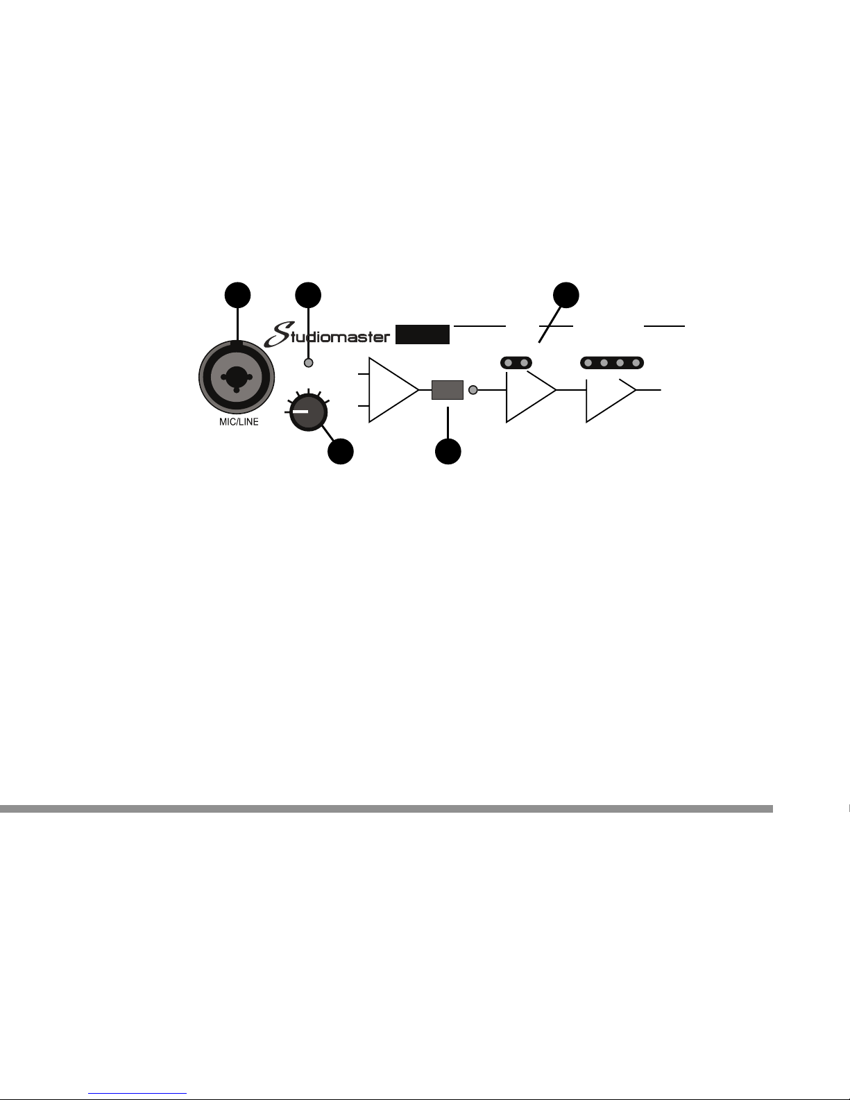
1. Mic/Line input sockets:
Combination XLR and jack. Suitable for use with balanced low
impendance microphones or line level signals typically from
mixing consoles. For convenience there are two sockets fitted,
one on the front and one on the rear panel. Only connect one
microphone or signal at any time.
2. +48V LED:
Illuminates when phantom power is turned on - see rear panel
controls and features.
3. VOICE control:
A six position switch marked SOFT to LOUD that refers to your
average voice level. This switch adjusts the gain of the VMS to
give the best setting for your particular voice. See SETUP
section for more details.
4. BYPASS switch:
Pressing this allows you to hear your voice unprocessed for
comparison purposes. Note the LEDs associated with the gate,
compressor, graphic and DSP turn off and the BYPASS LED
illuminates giving a visual indication of status.
5. NOISE GATE status LEDs:
The noise gate automatically turns the microphone off when you
stop singing. This reduces the unwanted background noise the
microphone would otherwise pick up. The open and closed LEDs
give a visual indication of the noise gate status.
The controls for the NOISE GATE are located on the rear panel see rear panel controls and features for more details.
1 2 5
3 4
EXPECT THE BEST
EXPECT THE BEST
+48V
SOFT
VOICE
LOUD
MIC/LINE
INPUT
MIC PRE
VMS
CLOSED OPEN 20 15 10 5dB
COMPRESSOR
/ LIMITER
NOISE
GATE
BYPASS
GAIN REDUCTION
Page 6
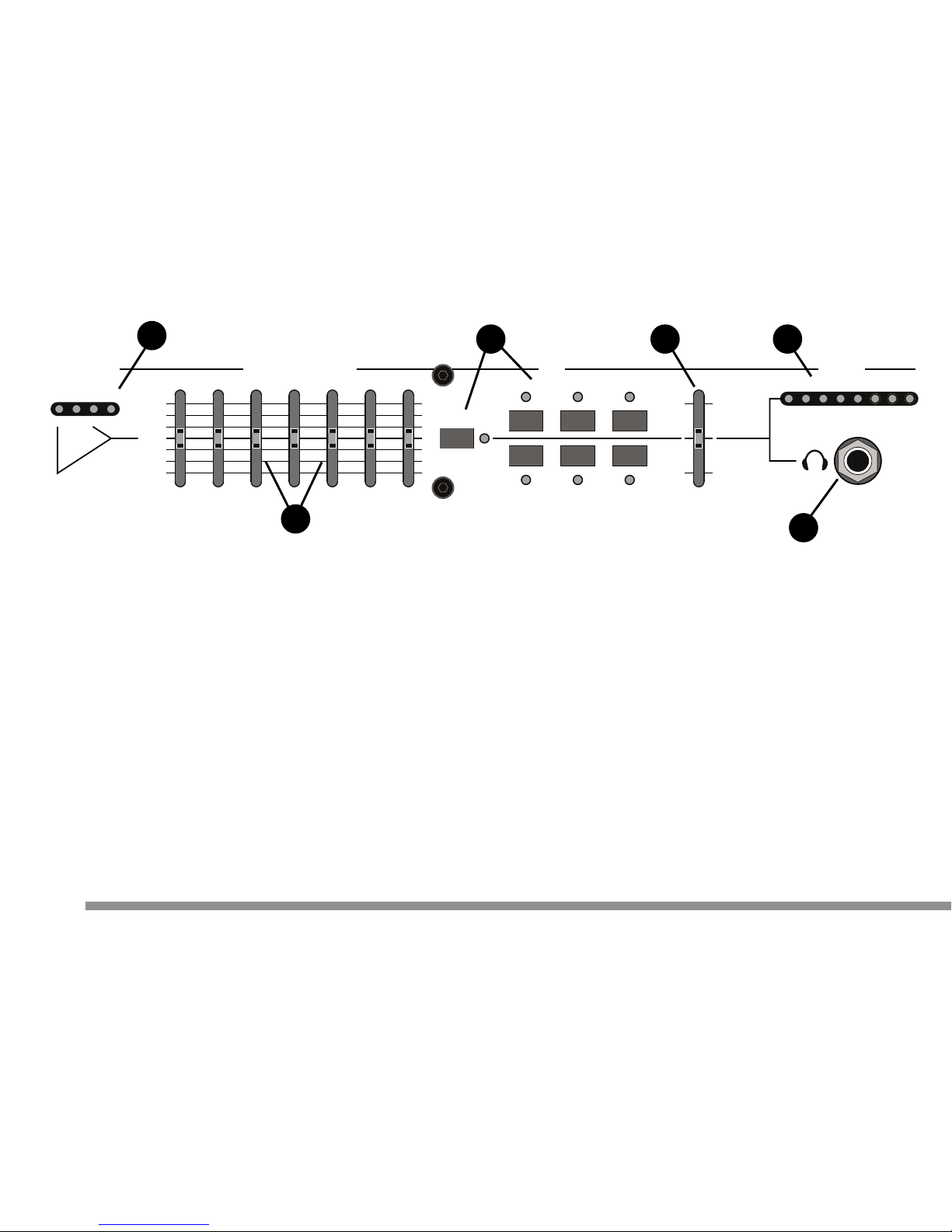
6. COMPRESSOR/LIMITER status LEDs:
Shows how much compression is being applied to your voice.
The first green (5dB) LED shows small amounts of compression
whilst the red (20dB) LED shows maximum compression has
been reached.
See SETUP section for more details.
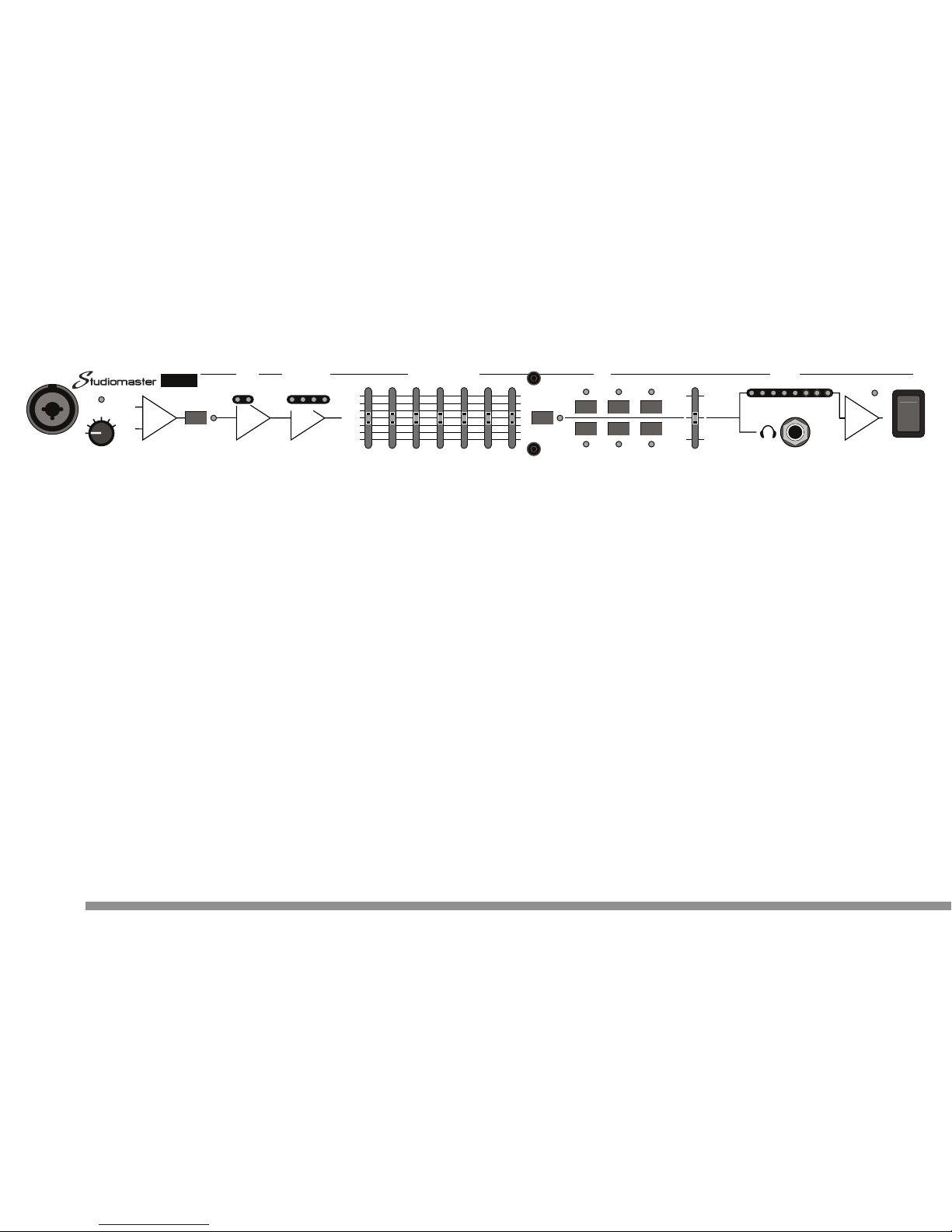
7. GRAPHIC EQUALISER (EQ):
Is a seven band tone control section. Unlike the graphic
equalisers found on most professional equipment, this uses
special frequencies dedicated to vocals, allowing fine adjustment
of your individual tonal qualities.
8. DSP - digital signal processor:
Contains six preset sound effects tailored to the voice.
Controls consist of an on/off switch with green status LED, six
effect switches and effects level control.
When an effect has been selected for more than 10 seconds that
selection is automatically restored the next time the VMS is
turned on.
9. OUTPUT level bargraph:
Using eight LEDs gives instant visual indication of the signal
level through the VMS in active and BYPASS modes.
10. Headphone socket:
Stereo jack socket for use with most headphones.
Warning: The signal level to the headphone socket is internally
set. To avoid damage to your hearing, connect the headphone
plug before placing the headphones over your ears.
Adjust (lower) the volume by sliding the headphones slightly
forward, away from your ears.
4
6
10
7
8 8 9
www.studiomaster.com
www.studiomaster.com
www.studiomaster.com
20 15 10 5dB
COMPRESSOR
/ LIMITER
FLAT
+9dB
-9dB
GAIN REDUCTION
GRAPHIC EQUALISER
125Hz 250Hz 500Hz 1kHz 2kHz 4kHz 8kHz
VOCAL1
ADT
SMALL REV
CHORUS
LARGE REV
ECHO
-40 -30 -20 -10 -5 0dB +5 +10
DSP OUTPUT
DSP ON
DSP LEVEL
+
_
Page 7
LINE
AMP
-40 -30 -20 -10 -5 0dB +5 +10
OUTPUT
POWER
I
O
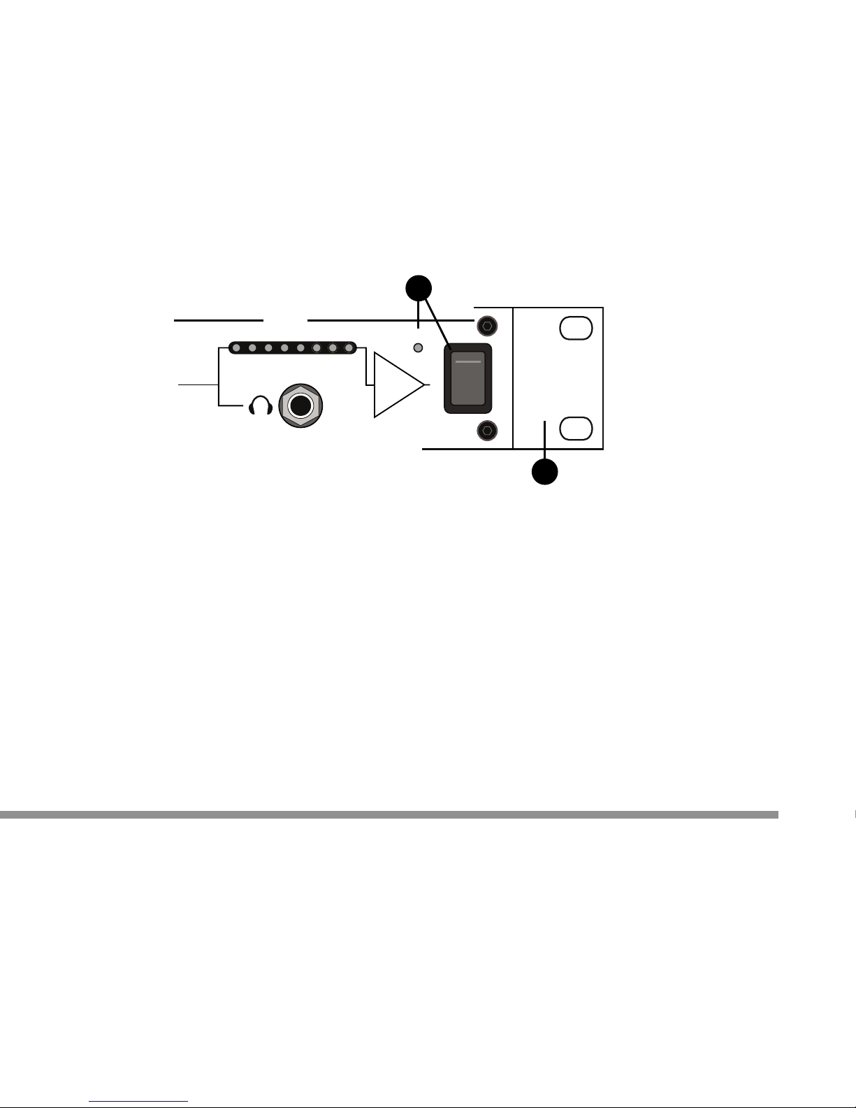
11. Power switch and LED:
Turns the VMS on or off. The blue LED illuminates when the
VMS is on.
12. Rack mount brackets:
The VMS is supplied ready for installation into a standard 19"
rack. For free standing use, remove the 3 Philips screws on each
bracket. The VMS is packed with four screw-in feet that can be
fitted to the under side of the unit. Retain the brackets and
screws for future use.
5
11
12
EXPECT THE BEST
EXPECT THE BEST
EXPECT THE BEST
Page 8
INPUT MIC - XLR
LINE - JACK
+48V
PHANTOM
HI-PASS
FILTER
DSP
FOOTSWITCH
www.studiomaster.com
NOISE GATE
DESIGN AND ENGINEERING IN ENGLAND
BY
STUDIOMASTER &
COURT ACOUSTICS
Vocal Management System
NORMAL
-20dB-60dB
VMS
OFF
ON
THRESHOLD
6
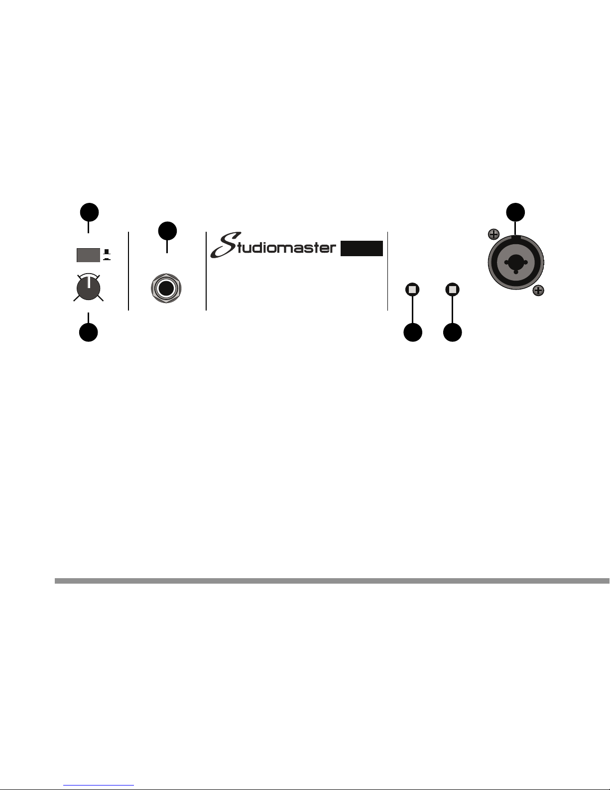
Controls & Features - Rear Panel
1. Mic/Line input sockets:
Combination XLR and jack socket suitable for use with balanced
low impendance microphones or line level signals typically from
mixing consoles. Only connect one microphone or signal at any
time.
2. +48V PHANTOM:
Switch applies 48 Volts to both XLR input sockets to power
condenser microphones. A red LED on the front panel
illuminates when switched on (in position). Most modern
condenser microphones have a working voltage range of 9 to
50V.
However, if in doubt check with the microphone manufacturer.
3. HI-PASS FILTER:
Cuts very low frequencies reducing handling noise, stage rumble
and wind noise. The VMS is shipped with the filter already active
(switch in position) as it will aid vocal clarity.
4. DSP FOOTSWITCH:
Jack socket allows connection of a foot switch (not supplied) to
turn on and off the DSP effects. Use any latching or change over
type foot switch.
5. NOISE GATE on/off switch:
Turns on and off the noise gate.
6. NOISE GATE THRESHOLD control:
Adjusts the threshold or level at which the noise gate turns on.
15
236
www.studiomaster.com
www.studiomaster.com
4
Page 9
SEND/RETURN
INSERT
DIRECT
OUT
BALANCED OUTPUT
230V Range : 50/60Hz 55mA
115V Range : 50/60Hz 110mA
LINE
MIC
ASSEMBLED IN CHINA
LEVEL
7
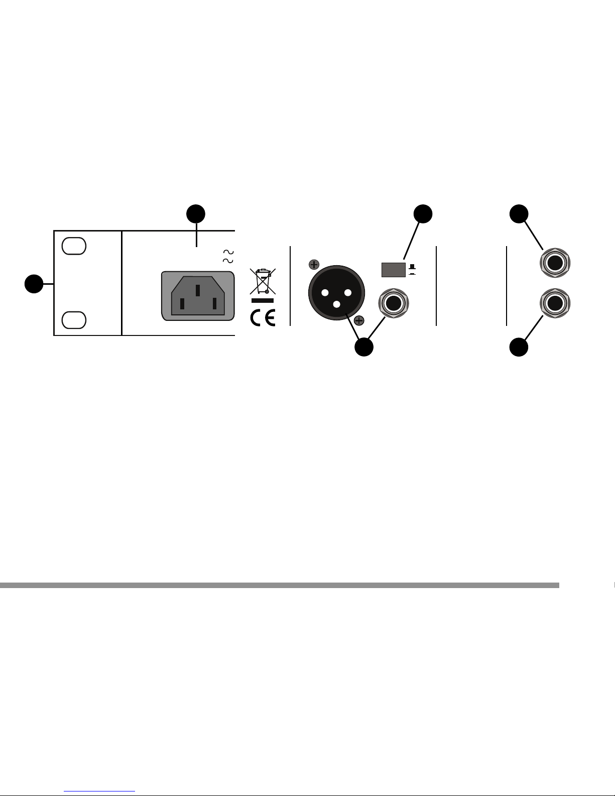
7. DIRECT OUTPUT:
Jack socket positioned in the circuit after the effects &
send/return insert but before the main output, bargraph and
headphones socket. This socket is useful for connecting to
external equipment for triggering effects etc.
8. SEND / RETURN INSERT:
Jack socket positioned in the circuit after effects but before direct
output, main output, bargraph and headphones socket. Useful for
connecting to external equipment for additional processing etc.
9. BALANCED OUTPUT LEVEL switch:
Changes output signal level from line (suitable for line inputs on
mixers, amplifiers etc) to mic (suitable for mic inputs on mixers,
computers etc).
10. BALANCED OUTPUT sockets:
XLR and Jack socket. Can be used balanced or unbalanced see connector wiring section.
11. A.C. power input socket.
12. Voltage selector (located on the side panel):
Read the Safety Instruction before attempting to move this
switch. Never make any adjustment with the A.C. power
cord/mains lead attached.
9 7
11
10
12
EXPECT THE BEST
EXPECT THE BEST
8
Page 10

Although the VMS contains a number of highly sophisticated
signal processing circuits, it is very easy to setup and use. We
recommend whatever level of audio experience, you read the
following section to get the best from this product.
1 Connecting up and checking control settings:
- Connect a microphone to either front or rear panel
MIC socket.
- Connect the output to your mixer, sound system etc.
- Check the NOISE GATE switch on the rear panel is
in the off (out) position.
- Connect the A.C. power cord / mains lead and switch
on, noting that the blue POWER LED illuminates.
- Check the DSP is turned off, confirmed by adjacent
green LED not illuminated.
- Check the VMS is in BYPASS mode, confirmed by
the adjacent red LED illuminating.
2 Getting sound:
- Sing into the microphone and adjust the VOICE
switch until one or two yellow (marked 0dB, +5) LEDs
on the bargraph illuminate with the loud parts of your
voice.
- Adjust your mixer or sound system for a suitable
volume level.
3 Activate your VMS!
- Release the BYPASS switch. Now when you sing into
the microphone the gain reduction LEDs illuminate
8
HOW TO MAKE IT WORK
SETTING UP THE VMS
www.studiomaster.com
www.studiomaster.com
www.studiomaster.com
VMS
VMS
Page 11
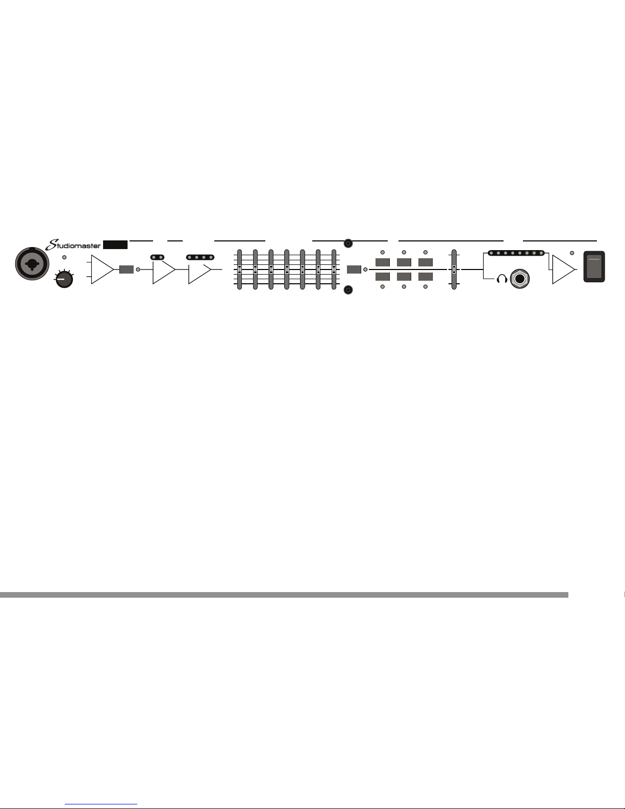
confirming correct operation. Your voice will now
sound warmer and have a more consistent volume.
- Typically the yellow and green gain reduction
(marked 15, 10, 5dB) LEDs flash when singing
showing normal operation. However, by adjusting the
VOICE control more or less LEDs illuminate showing
more or less compression being applied.
Experimenting with this control will find the best setting
for your voice.
4 Graphics:
If required make subtle tonal adjustments using the
graphic equaliser. However, if you are happy with the
tonal sound of your voice leave the graphic controls in
the central position.
5 The noise gate:
- Set the THRESHOLD control (on the rear panel) to
the centre, NORMAL position and switch on (in
position).
Note the red gate closed LED illuminates and back
ground noise disappears. As soon as you start to sing
the green gate open LED illuminates and your voice is
allowed through the VMS.
- The THRESHOLD control can be adjusted, if
required, for sensitivity. If the gate turns on too early,
'clips' certain sounds or words, the THRESHOLD
control should be turned anti-clockwise (towards -
60dB) slowly to increase its sensitivity. If the gate
appears too sensitive and never seems to close, turn
the THRESHOLD control clockwise (towards -20dB) to
reduce sensitivity.
9
EXPECT THE BEST
EXPECT THE BEST
EXPECT THE BEST
+48V
SOFT
VOICE
L
OUD
MIC/LINE
INPUT
MIC PRE
LINE
AMP
Vocal Management System
VMS
CLOSED OPEN 20 15 10 5dB
COMPRESSOR
/ LIMITER
NOISE
GATE
BYPASS
FLAT
+9dB
-9dB
GAIN REDUCTION
GRAPHIC EQUALISER
125Hz 250Hz 500Hz 1kHz 2kHz 4kHz 8kHz
VOCAL1
ADT
SMALL REV
CHORUS
LARGE REV
ECHO
-40 -30 -20 -10 -5 0dB +5 +10
DSP OUTPUT
DSP ON
DSP LEVEL
+
_
POWER
I
O
Page 12
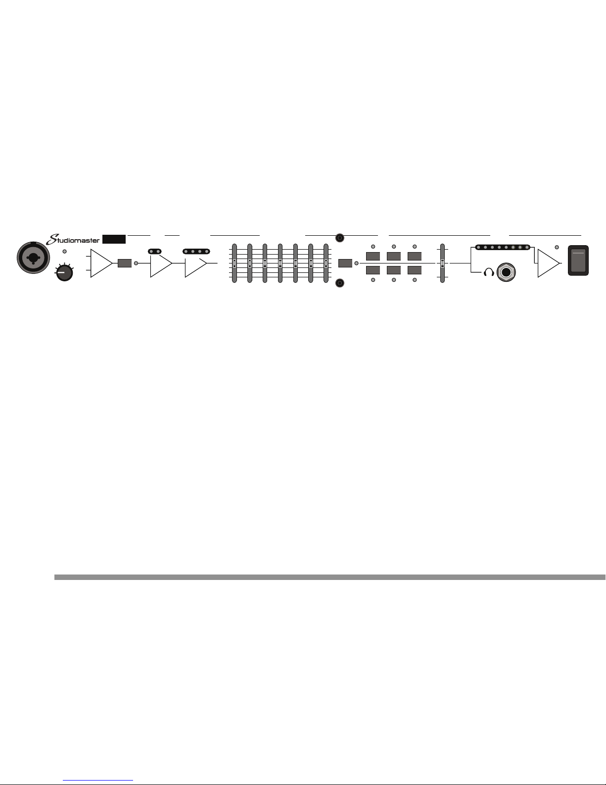
5 Finally - Adding effects:
Turn on the DSP, select VOCAL 1 (the most popular
effect on Studiomaster DSPs) and whilst singing,
adjust the DSP LEVEL control until the desired effect is
achieved.
That's it - you are ready for the performance!
10
www.studiomaster.com
www.studiomaster.com
+48V
SOFT
VOICE
LOU
D
MIC/LINE
INPUT
MIC PRE
LINE
AMP
Vocal Management System
VMS
CLOSED OPEN 20 15 10 5dB
COMPRESSOR
/ LIMITER
NOISE
GATE
BYPASS
FLAT
+9dB
-9dB
GAIN REDUCTION
GRAPHIC EQUALISER
125Hz 250Hz 500Hz 1kHz 2kHz 4kHz 8kHz
VOCAL1
ADT
SMALL REV
CHORUS
LARGE REV
ECHO
-40 -30 -20 -10 -5 0dB +5 +10
DSP OUTPUT
DSP ON
DSP LEVEL
+
_
POWER
I
O
Page 13

GENERAL
Always use a good quality microphone that is suitable for your
style of singing and that you like the sound of. Your dealer can
show you mics specially designed for the voice. The VMS can
use dynamic or condenser type microphones so there is a big
choice available. It's time well spent getting the right mic.
Learn good microphone technique and avoid the obvious pitfalls.
Singing too far away from the mic will give poor signal and more
background noise whilst too close will cause distortion and poor
clarity. Sing directly into the mic (not on the side) at a distance
that suits you and the microphone.
Finally, never blow into a mic to test it. Your mic is a precision
instrument designed for the delicate vocal sounds - a hurricane
will destroy that precision!
COMPRESSOR / LIMITER
The dynamics of this compressor are internally set to give
optimum results on the human voice making a complex
electronic device like this easy to use. The SETUP section
outlines how to adjust the VOICE control to give good results.
However, turning the VOICE control clockwise will increase the
gain and so drive the compressor harder. This will give a slightly
thicker vocal sound with less dynamics. Turning the VOICE
control anti-clockwise will result in less compression giving a
slightly more open sound.
Experimentation may reveal 'your' perfect sound.
GRAPHIC EQUALISER (EQ)
The first point to mention here is if you are happy with the sound,
leave the 7 controls in the centre (off) position. More
performances have been ruined by too much EQ than not
enough.
Before making any EQ adjustments first consider the sound
source. Am I to close/too far away from the mic? Is it the wrong
type of mic? Is the speaker system in the wrong position? It is
much better to solve tonal problems at source rather than try to
'fix' them with an equaliser.
The 125Hz frequency is useful for reducing handling and low
frequency background noise.
The 8kHz frequency, although outside the range of the human
11
EXPECT THE BEST
EXPECT THE BEST
HOW TO SOUND GREAT
HINTS & TIPS
VMS
VMS
Page 14
voice, is helpful in reducing sibilance.
Try cutting (lowering) either control and listen to the difference.
NOISE GATE
This is a great device for cutting out unwanted background
sounds and instrument overspill during your performance.
In live applications its setting will always be a compromise due to
the environment the performance takes place in. If the
background noise (from stage monitors, drum kits, guitars etc) is
almost as loud as your voice, a noise gate is limited in what it
can do. With this in mind, try to avoid directing the microphone to
other loud sound sources.
Carefully adjust the threshold control so that it doesn't close on
quiet passages or between songs when talking.
DSP - Digital Signal Processor
You will find all six effects on the VMS sound great with both
male and female voices, the choice of which effect is your
preference.
The DSP LEVEL control adjusts the volume of the effect that will
be mixed with your original voice. Avoid adding too much of the
effect, especially reverb, as it can make the voice sound distant,
losing impact. Likewise, not enough effect can be too subtle for a
live performance leaving the voice sounding dry.
Make use of the foot switch socket to turn on and off the DSP
remotely between songs. Speaking between songs is far clearer
without any effects.
Vocal 1: a combination of reverb and delay developed by
Studiomaster and the choice of many professional performers
world wide.
Small & Large Reverb: good quality reverbs great for ballads.
ADT - automatic double tracking: A technique used in the 60s
which adds a small delay to the voice giving a thicker, more
powerful vocal.
CHORUS: A modern, subtle effect that works well with voices in
the upper range.
ECHO: a classic rock & roll delay with several repeats.
12
www.studiomaster.com
www.studiomaster.com
www.studiomaster.com
Vocal Management System
+48V
SOFT
VOICE
L
OUD
MIC/LINE
INPUT
MIC PRE
LINE
AMP
Vocal Management System
VMS
CLOSED OPEN 20 15 10 5dB
COMPRESSOR
/ LIMITER
NOISE
GATE
BYPASS
FLAT
+9dB
-9dB
GAIN REDUCTION
GRAPHIC EQUALISER
125Hz 250Hz 500Hz 1kHz 2kHz 4kHz 8kHz
VOCAL1
ADT
SMALL REV
CHORUS
LARGE REV
ECHO
-40 -30 -20 -10 -5 0dB +5 +10
DSP OUTPUT
DSP ON
DSP LEVEL
+
_
POWER
I
O
Page 15

13
EXPECT THE BEST
EXPECT THE BEST
EXPECT THE BEST
CONNECTOR WIRING
Pin 3 - Negative / Cold / -Ve phase
Pin 2 - Positive / Hot / +Ve phase
Pin 1 - Screen / Ground / Earth
Pin 3 - Negative / Cold / -Ve phase
Pin 1 - Screen / Ground / Earth
Pin 2 - Positive / Hot / +Ve phase
Pin 3 - Link to Pin 1
Pin 1 - Screen / Ground / Earth
Pin 2 - Signal
Ring - Negative / Cold / -Ve phase
Tip - Positive / Hot / +V
e phase
Sleeve - Screen / Ground / Earth
Tip
Ring
Sleeve
Tip
Tip - SignalSleeve
Sleeve - Screen / Ground / Earth
Tip
Tip - ControlSleeve
Sleeve - Screen / Ground / Earth
INPUT XLR OUTPUT XLR (BALANCED) OUTPUT XLR (UNBALANCED)
INPUT / OUTPUT 1/4" TRS JACK (BALANCED) OUTPUT 1/4" TS JACK (UNBALANCED) SEND/RETURN 1/4" TRS JACK
Ring - Return
Tip - Send
Sleeve - Screen / Ground / Earth
Tip
Ring
Sleeve
DIRECT OUTPUT 1/4" TS JACK FOOTSWITCH 1/4" TS JACK HEADPHONES OUTPUT 1/4" TRS JACK
Ring - Signal
Tip - Signal
Sleeve - Screen / Ground / Earth
Tip
Ring
Sleeve
For use with 30 - 400ohm headphones
Tip
Tip - SignalSleeve
Sleeve - Screen / Ground / Earth
Page 16

VMS
VMS
14
www.studiomaster.com
www.studiomaster.com
No Power On Led.....
Check A.C. power cord/mains lead is connected to the
VMS & wall supply and is switched on.
UK only - Check fuse in mains plug.
Check A.C. power cord/mains lead is fully pushed into the
rear panel socket
Check the VMS is switched on, and blue power on LED is
illiuminated.
No sound.....
Check for a signal on the front panel bargraph.
Signal on bargraph - check connection to the
mixer/amplifier.
No signal on bargraph - check the microphone is
connected (switched on if it has a switch) and the noise
gate is switched off.
Sound is lifeless or distorted.....
Using the mic too close to the mouth or too much gain move away from the mic slightly or turn the VOICE control
toward the LOUD setting (anti-clockwise).
Sound is thin or distant.....
Too far away from the mic or not enough gain - move
closer to the mic or turn the VOICE control toward the
SOFT setting (clockwise) and check gain reduction LEDs
are illuminating.
WHY IS IT NOT WORKING!
TROUBLE SHOOTING
Page 17

15
EXPECT THE BEST
EXPECT THE BEST
FACTS & FIGURES
TECHNICAL SPECIFICATION
Gain VOICE switch 0dB, 10dB, 16dB, 22dB, 28dB, 34dB
CMMR Microphone input 86dB @ 1kHz
EIN Microphone input -126dBu
Frequency Response
+0, -0.5dB 20Hz - 20kHz
(BYPASS selected)
Noise BYPASS selected < -90dB
Active < -76dB
HI-PASS Filter 80Hz 18dB / octave
GATE characteristics
Threshold variable -60dBu to -20dBu
Filter -3dB @ 150Hz & 5kHz
COMPRESSOR characteristics
Optimised for vocal characteristics
Distortion
BYPASS selected < 0.002%
Active < 0.2%
Metering
Output levels leds illuminate -40, -30, -20, -10, -5, 0, +5, +10dBU
'VU' = 0dBu output, averaging response characteristic
Gain reduction leds illuminate 5dB, 10dB, 15dB, 20dB gain reduction
Graphic EQ
Gain +/- 9dB
Frequencies 125, 250, 500, 1k, 2k, 4k, 8kHz
Response Q = 1.4
Input / Output impedance & levels
Microphone input 2k5 ohms
Line input (20dB pad) 25k ohms
Maximum input level +22dBu (mic) +42dBu (line)
Maximum output level +28dBu (bal) +22dBu (unbal)
Output impedance 150 ohms (line) 200 ohms (mic)
Power Requirements
230V range +/-10%, ~50/60Hz, 55mA Max
115V range +/-10%, ~50/60Hz, 110mA Max
Dimensions Width 482mm (19") including rack ears
Height 44mm (1.75") 1U
Depth 265mm (10.5")
Weight Net 3.6KG (7.92lbs) Gross 4.6KG (10.12lbs)
Page 18

VMS
VMS
The Manufacturer warrants all Studiomaster products to be free
from defects in materials and workmanship for a period of one
year from date of purchase. The Manufacturer reserves the right
to the final decision on all warranty claims.
Exclusions to Warranty Cover
Damage caused by accident, misuse, improper
installation or neglect.
Damage caused by repair, modification or service by
persons not authorised by Studiomaster.
Products on which the serial number has been
defaced, altered or removed.
Who is Protected
This warranty is enforceable by the original purchaser and any
subsequent owner(s) during the warranty period, providing a
copy of the original sales receipt is submitted whenever a
warranty service is required.
It is recommended that you complete and mail the Warranty
Registration Card supplied with your product.
For your reference in the event of a warranty or service repair,
please complete the following information and attach a copy or
your original sales receipt.
Model :
Serial Number :
Purchase Date :
Purchased From :
Note : THIS WARRANTY DOES NOT AFFECT YOUR
STATUTORY RIGHTS
16
www.studiomaster.com
www.studiomaster.com
www.studiomaster.com
ARE YOU COVERED?
WARRANTY
Page 19

VMS
VMS
If you have a problem with your Studiomaster product or think it
has developed a fault you should first carefully check the Trouble
Shooting section in this guide. If this does not solve the problem
or if the product is physically damaged, contact your local dealer
or distributor for service details.
Should it be recommended you return the product to your
nearest Studiomaster Service Centre you must first contact
them.
You will be asked for the product type and serial number. You
will then be given a Returns Authorisation (RA) number.
Pack the unit in its original carton to protect it from shipping
damage.
You must have the Returns Authorisation number clearly marked
on the outside of the carton or we may refuse the delivery.
Studiomaster cannot be held responsible for damage resulting
from the equipment being packed incorrectly.
Label the equipment clearly with your name and address and
include a clear description of the fault. The more information you
supply helps the service engineer, minimising repair cost when
out of warranty.
Important : No liability will be accepted by Studiomaster for any
transit damage to units not returned in their original packing, for
warranty repairs or otherwise.
17
EXPECT THE BEST
EXPECT THE BEST
EXPECT THE BEST
In Accordance with our progressive product development, Studiomaster / Studioking
reserve the right to change features and specifications without prior notice.
HOW TO GET MY PRODUCT REPAIRED
SERVICE INFORMATION
Page 20
www.studiomaster.com
Studioking Limited
7 Eden Way, Pages Industrial Park, Leighton Buzzard, Bedfordshire LU7 4TZ UK
Tel : 44 (0)1525 217111 Fax : 44 (0)1525 378466 Email : [email protected]
EXPECT THE BEST
EXPECT THE BEST
VMSM ENG V2
SEND/RETURN
INSERT
DIRECT
OUT
BALANCED OUTPUT
230V Range : 50/60Hz 55mA
115V Range : 50/60Hz 110mA
N
LINE
MIC
ASSEMBLED IN CHINA
+48V
SOFT
VOICE
LOUD
MIC/LINE
INPUT
MIC PRE
Vocal Management System
VMS
CLOSED OPEN 20 15 10 5dB
COMPRESSOR
/ LIMITER
NOISE
GATE
BYPASS
FLAT
+9dB
-9dB
GAIN REDUCTION
GRAPHIC EQUALISE
R
125Hz 250Hz 500Hz 1kHz 2kHz
-60d
B
LEVEL
 Loading...