

Page 1
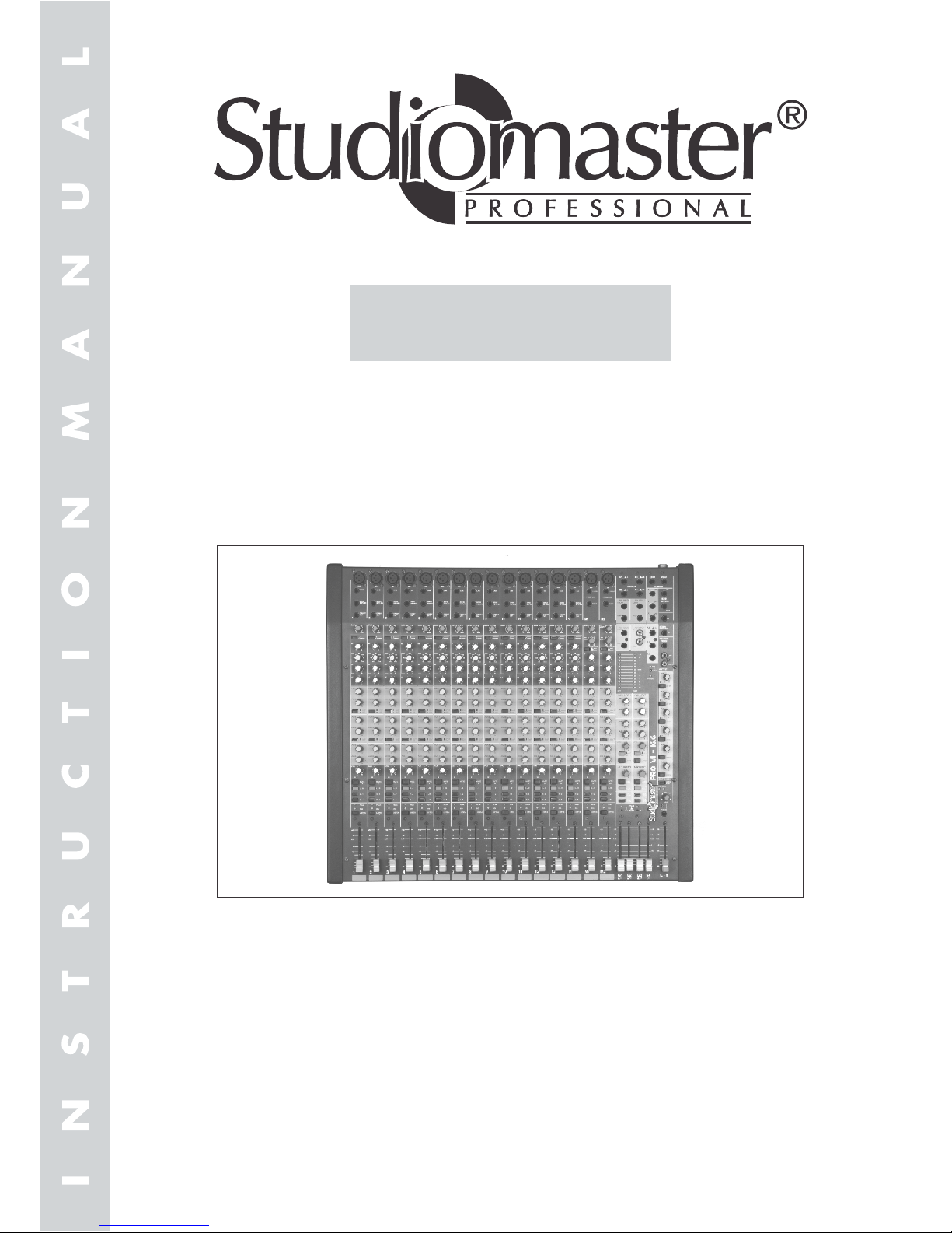
PRO VI SERIES
Models :
PRO VI 16.6,
PRO VI 24.6
Page 2

Contents
4 For the mono channels:
For the stereo channels:
7 Level controls (faders) for the mono channels.
9 2-way tone controls for the stereo channels
“HI” for the high frequencies (±15dB/12kHz)
“LO” for the bass frequencies (±15dB/45Hz)
10 Peak program meter
11 Power LED
12 Phantom power LED:
1 Operating Elements and Connections
upper control: for adjusting the filter frequency
(250-6000Hz)
lower control: for boosting or attenuating
(±15dB) the midrange frequencies
“LO” for the bass frequencies (±15dB/60Hz)
2 3-way equalizers for the mono channels :
“HI” for the high frequencies (±15dB/12kHz)
“MID” for the midrange frequencies:
1.1 Front panel
1 Operating Elements and Connections ............ 1
2 Safety Notes ................................................... 3
3 Applications .................................................... 3
4 Modification of the Input Channels ................. 3
4.1 Switching off the phantom power
for individual channels(mono channels) or
switching it on (stereo channels) .................... 4
4.2 Modifying the signal take-off points
for the send ways ‘AUX’ and ‘MON’ ................ 4
4.3 Modifying the signal take-off points
for the direct outputs ....................................... 4
5 Connection of units ......................................... 4
5.1 Audio sources ................................................. 4
5.1.1 Microphones ................................................... 4
5.1.2 Units with line output level .............................. 5
5.2 Inserting units for sound processing ............... 5
5.3 Effect units ...................................................... 5
5.4 Headphones ................................................... 5
5.5 Recorders ....................................................... 5
5.6 Amplifier .......................................................... 5
6 Operation ........................................................ 6
6.1 Basic adjustment of the input channels .......... 6
6.2 Adjustments for the send ways ....................... 6
6.3 Mixing the audio sources ................................ 7
6.4 Monitoring via headphones ............................. 7
7 Specifications .................................................. 7
8 Glossary .......................................................... 8
1
1 Gain controls for adjusting the input amplification for
the channels (for the stereo channels, the control is
effective for the micro phone inputs only)
3 Controls for mixing the signals of the channels 1-16
respectively to the “AUX” send way (post-fader) and
the “MON” send way (pre-fader)
Note: For both send ways, the signal take-off points
can be internally modified separately for each
individual channel (to be performed by skilled
personnel only). See chapter 4.2.
Panorama controls “PAN” for placing the mono
signal on the stereo base.
Balance controls “BAL” for adjusting the level
ratio of the right and left channels.
5 Indication LEDs “PK” serve either as overload
indications or as PFL indications.
6 PFL buttons for the channels:
For pre-fader listening (PFL) to the respective
channel via headphones connected to the jack; with
the button pressed, the led “PK” of the channel will
light permanently and the peak program meter will
show the pre-fader level of the channel.
8 Selector switches for adjusting the input amplification
for line sources connected to the stereo channels.
Button not pressed:
Low amplification for professional units with an output
level of +4dBu
Button pressed:
Higher amplification for semi-professional units with
an output level of -10dBu
Lights up if the 48V phantom power for the
microphone inputs of the mono channels has been
switched on with the switch “PHANTOM POWER
+48V”
a) If none of the PFL buttons has been pressed, the
level of the master signal at the jacks “ MAIN MIX
OUTPUT” will be indicated.
b) If one or more PFL buttons have been pressed,
the level of the selected input channels is
indicated pre-fader.
a) If the PFL function has not been activated for the
channel (button PFL not pressed), the LED will
light up shortly to indicate that the channel signal
has reached its maximum level at which it is close
to overload; the LED will permanently show red
to indicate overload of the channel.
b) With the PFL function activated for the channel
(button PFL pressed), the LED will light
permanently.
Page 3

1.2 Rear panel
22 Stereo replay input (phono, unbal.) for connecting
the replay output of the recorder connected to the
jacks “RECORD” or another unit with line output
level (e.g. CD player)
23 Insert jacks for inserting a unit for sound process ing (e.g. graphic equalizer) into the left and right
channels of the master output; for connection see
chapter 5.2
Piug connections:
Tip = send (output)
Ring = return (input)
Body = ground
24 Recessed switch for connection of the 48V phant om power for all jacks “MIC” of the mono channels;
required for connecting capacitor or electret micro phones operating at a 48V phantom power.
Caution!
To prevent switching noise, only actuate the switch
with the mixer switched off. Please also observe the
safety note in position 28!
25 Mono outputs (6.3 mm jack, unbal.) respectively for
the send way “AUX” and the send way “MON”
26 Stereo input (6.3 mm jack, bal.) for connecting an
additional unit with the output level.
Note: In case of a mono unit, only use the upper
jack “AUX-IN-LEFT”. The signal is then inter nally switched to the right and left channels.
27 Stereo inputs (6.3 mm jack, bal.) for stereo channels
for connecting stereo units with line output level.
Note: In case of a mono unit, only use the upper jack
“LINE-LEFT”. The signal is then internally swi tched to the right and left channels.
28 Microphone inputs (XLR, bal) for the mono channels.
Caution!
With the phantom power switched on (yellow LED
“PHANTOM POWER + 48V” lights up), all micropho ne inputs of the mono channels are supplied with a
48V phantom power.
In this case, never connect any unbalanced microp hones as they might be damaged.
Note: The phantom power can be switched off inter nally for individual mono channels or switched
on for individual stereo channels (to be perfor med by skilled personnel only!).
See chapter 4.1.
29 Mono inputs (6.3 mm jack, bal.) for the channels for
connecting mono units with line output level.
30 Insert jacks for inserting units for sound processing
(e.g. compressor) into the mono channels.
For connection see chapter 5.2.
Plug connections:
Tip = send (output)
Ring = return (input)
Body = ground
31 Direct outputs (6.3 mm jack, unbal.) for the mono
channels this is where the processed channel
Signals are available after their faders.
They can be fed e.g. to a multi track recorder or to a
second mixer.
Note: The signal take-off point can be modified inter nally to pre-equalizer separately for each indi vidual channel (to be performed by skilled pe rsonnel only!). See chapter 4.3.
32 5 pin male plug connector is fitted to the diamond
24-4-2DX & 16-4-2DX & EP7 is fitted with 5 pin fe male plug connector.
2
20 Stereo master output (XLR, bal.) for connecting the
power amplifier of the PA system.
21 Stereo recording output (phono, unbal.) for conne cting the input of a recorder, the recording level is
adjusted with the control “RECORD LEVEL” and it
additionally depends on the position of the master
faders.
13 Level control for the recording output “RECORD”
14 Master controls respectively for the send way
“AUX” and the send way “MON”
15 Level control for the input “PLAYBACK”
16 Level control for headphones connected to the
jack below.
17 6.3 mm jack for connecting stereo headphones
(Minimum impedance)
a) For monitoring the master signal at the jacks
“MAIN MIX OUTPUT” if none of the PFL buttons
has been pressed or
b) For pre-fader listening to the input channels
selected with the PFL buttons
18 Level control for the additional stereo line input
“AUX-IN”
19 Master faders (”L” (left)/”R” (right) for level adjustm ent of the stereo master signal at the jacks
“MAIN MIX OUTPUT”
Page 4

2 Safety Notes
3 Applications
4 Modification of the Input Channels
If required, perform the following modifications of the
input channels prior to connecting the mixer.
Attention!
These modifications require a lot of effort. As it is necessary to open the unit and to remove the PCBs of the
corresponding input channels, they may be performed
by qualified, skilled personnel only.
1) Switch off the mixer and always disconnect the
mains plug from the mains socket.
1. The wire which is coloured Green and Yellow mu st be connected to the terminal in the plug which
is marked with the letter E or by the earth symbol
or coloured Green & Yellow.
2. The wire which is coloured Blue must be connec ted to the terminal which is marked with the letter
N or coloured Black.
3. The wire which is coloured Brown must be conn ected to the terminal which is marked with the le tter L or coloured Red.
Warning - This appliance must be earthed.
- Gain controls in the mono channels; in the stereo
channels, gains controls for the microphone inputs
and level selector switches for the line inputs.
- +48V phantom power to be connected for all micro phone inputs of the mono channels*
- 3-way equalizers with semi-parametric midrange
control for the mono channels. 2-way tone controls
for the stereo channels.
- One control each for the send way “AUX” (post fader*) and the send way “MON” (pre-fader*)
- Direct outputs (post-fader*) and insert jacks for the
mono channels.
- PFL button for pre-fader listening via headphones
- LED for indicating PEAK and PFL.
The mixer is ideally suited for installation into a rack
for units of a width of 482 mm (19”). In the rack, 6 RS
(rack spaces) = 267 mm are required. However, the
unit can either be placed as desired or installed into a
console.
* This function may be modified, if required. As the
unit has to be opened for this purpose, the modific ation must be performed by skilled personnel only.
- see chapter 4.
The mixer with 16/24 input channels for microphones
or units with line output level is specially designed for
musicians and stage applications. The mono channels
and stereo channels can be mixed to a stereo master
channel and two send ways. The input channels are
provided with various adjusting facilities. e.g.:
The wires in this mains lead are coloured in accorda nce with the following code in power supply EP7:
Green/yellow = earth
Blue = neutral
Brown = live
As the colours of the wires in the mains lead of this
appliance may not correspond with the coloured
markings identifying the terminals in your plug,
proceed as follows:
Important for Customers!
If the unit is to be put out of operation definitively,
take it to a local recycling plant for a disposal which
is not harmful to the environment.
No guarantee claim for the unit or liability for any
resulting personnel damage or material damage will
be accepted if the unit is used for other purposes
than originally intended, if it is not correctly connect ed, operated, or not repaired in an expert way.
For cleaning only use a dry, soft cloth; never use
chemicals or water.
Never pull the mains cable when disconnecting the
mains plug from the socket, always seize the plug.
In any case the unit must be repaired by skilled pers onnel.
1 If there is visible damage to the unit or to the mains
cable.
2 If a defect might have occurred after the unit was
dropped or suffered a similar accident.
3 If malfunctions occur.
Do not operate the mixer or immediately disconnect
the plug from the mains socket.
Do not insert anything into the air vents! This may
results in an electric shock.
The heat generated within the unit must be carried
off by air circulation. Therefore, the air vents of the
housing must not be covered.
Do not place any vessel filled with liquid on the mixer,
e.g. a drinking glass.
The unit is suitable for indoor use only. Protect it
against dripping water and splash water, high air
humidity, and heat (admissible ambient temperature
range 0-40°C).
Please observe the following items in any case:
The unit is supplied with external power supply only use
power supplies recommended by studiomaster with
Diamond series. EP7 is supplied with hazardous mains
voltage (230V~). Leave servicing to skilled personnel
only. Inexpert handling may cause an electric shock
hazard. Furthermore, any guarantee claim will expire if
the unit has been opened.
Attention!
This unit corresponds to the directive for electromagnetic compatibility 89/336/EEC and to the low voltage directive 73/23/EEC.
3
Page 5

into the jack (CONN3).
And carefully remove the front plate from the bottom
part of the housing. The PCBs for the individual
channels are attached to the front panel. To facilita et handling, the electrical connection between the
front panel and the bottom part of the housing can
be separated: Disconnect the 4-pole cable plugged
5) It is now possible to carefully remove the PCB.
Take care not to tear off any connection cable.
6) Perform the desired modifications for the channel
according to chapters 4.1 to 4.3.
7) Reassemble the mixer. Prior to fastening the
screws to join the front panel and the bottom part
of the housing, make sure to connect the two parts
again via the 4-pole cable.
4.1 Switching off the phantom power for individual
channels (mono channels) or switching it on
(stereo channels).
The 48V phantom power for the mono channels can be
centrally connected by the switch ‘PHANTOM POWER
+ 48V’, however, it can be individually disconnected for
each of these channels for connecting both unbalanced
and phantom-powered microphones. For this purpose,
rearrange the jumper ‘CONN3’ in the field ‘+ 48V’ on the
PCB of the corresponding channel in such a way that it
links pin 1 and pin 2 of the plug contact.
4) Remove all operating elements and also the nuts
below the operating elements at the channel to be
modified. Also unscrew the fader, if required.
3) Unscrew the plate of the connection panel and
remove it.
Unscrew the screws at the edges of the front
panel and the screws arranged around the connec tion panel on the rear panel.
2) To remove the front panel
For the pre-fader send way ‘MON’, the signal take-off
point for each channel can be separately modified to
pre-equilizer or post-fader. For this purpose, rearrange
the jumper ‘JP2’ (close to the field ‘A2’) on the PCB the
corresponding channel according.
CON 3
CON 4
CON 3
2
2
2
3
3
3
ON
ON
OFF
Jumper ‘CONN3’ for phantom power of a mono
channel.
Jumper ‘JP1’ for the send way ‘AUX’
In the basic adjustment, the microphone inputs of the
stereo channels are not supplied with the 48V phantom
power if the switch ‘PHANTOM POWER + 48V’ has
been pressed. To switch it on for a channel, bridge the
pins 2 and 3 of the contact ‘CONN4’ in the field ‘+48V’.
Plug contact ‘CONN4’ for phantom
power supply of a stereo channel
PRE FADER
POST FADER
POST FADER
PRE FADER
PRE EQ
PRE EQ
POST FADER
JP2
JP3
Jumper ‘JP2’ for the send way ‘MON’
4.3 Modifying the signal take-off points for the direct
outputs.
For each individual direct output of the mono channels,
the signal take-off point can be modified from post-fader
(basic adjustment) to pre-equalizer. For this purpose,
rearrange the jumper ‘JP3’ (close to the field ‘DO’) on
the PCB of the corresponding channel accordingly.
4.2 Modifying the signal take-off points for the
send ways ‘AUX’ and ‘MON’.
For the post-fader send way ‘AUX’, the signal take-off
point for each channel can be separately modified to
pre-fader. For this purpose, rearrange the jumper ‘JP1’
(close to the field ‘A1’) on the PCB of the corresponding
channel accordingly.
Jumper ‘JP3’ for the direct output.
Note: The phantom power can be switched off internally
for individual mono channels or switched on for
individual stereo channels. See chapter 4.1.
Do not switch on the phantom power if unbalanced
microphones are connected! These microphones
might be damaged.
will result.
Only switch on or off the phantom power with the
mixer switched off, otherwise loud switching noise
Caution!
up.
For operating capacitor or electret microphones
using a 48V phantom power, the phantom power can be
switched on for all microphone inputs of the mono channels: Press the recessed switch ‘PHANTOM POWER
+48V’ by means of a thin object (e.g. ball point pen). All
microphone inputs of the mono channels will be supplied with a 48V phantom power and the yellow LED
‘‘PHANTOM POWER +48V’ on the front panel will light
Connect microphones or other low-impedance mono
signal sources with low output levels to the balanced
XLR jacks ‘MIC’.
5.1.1 Microphones
The input channels mono allow both connection of microphones and of units with line output level. As it is impossible to switch between microphone inputs and line
inputs, do not use both inputs simultaneously. Either
connect the microphone input or the line input of the
channel.
5.1 Audio sources
Prior to connecting any units or to changing any existing
connections, switch off the mixer and all other audio
units.
5 Connection of Units
4
Page 6
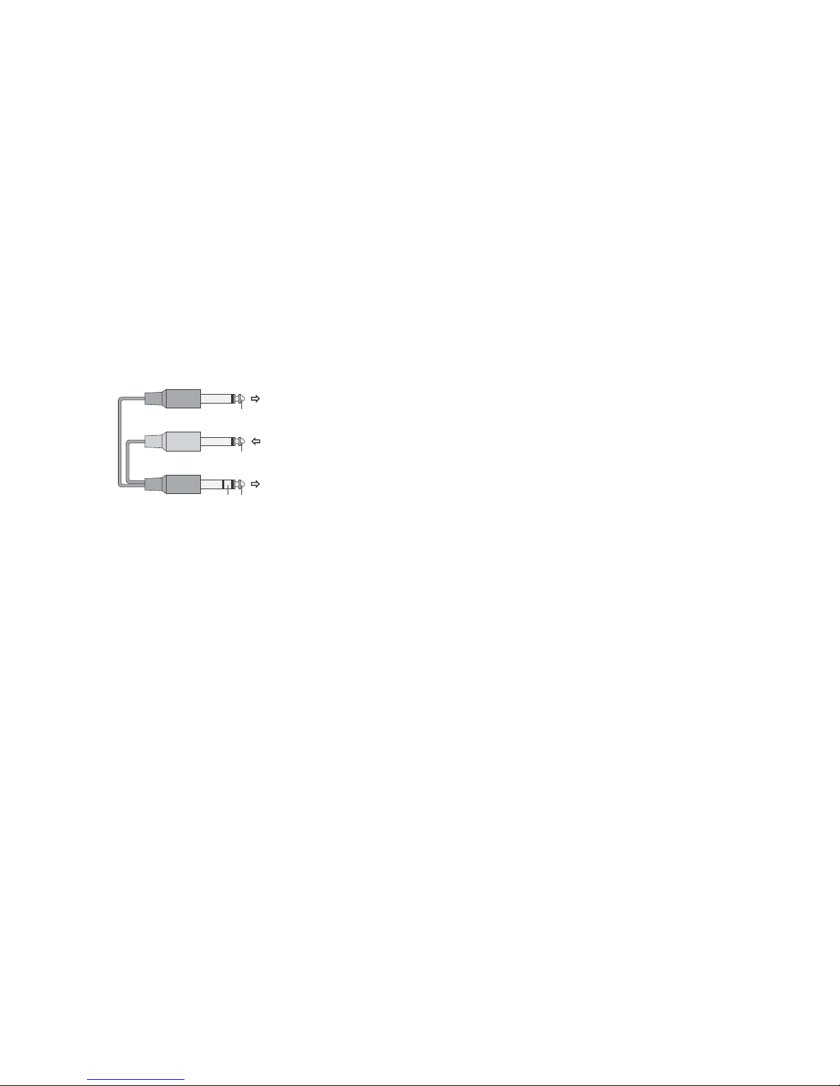
Via 6.3mm jacks ‘INSERT’ (31), units for sound
processing (e.g. compressors, noise gates) can be
inserted into the mono channels: The channel signal is
taken pre-fader via the insert jack, is completely routed
via the unit connected and returned via the same jack.
Connect the unit for sound processing via a Y cable.
Connect signal sources with line mono output to the
jacks ‘LINE’ of the channels mono. When connecting
mono units to the stereo channels or to the stereo input
‘AUX-IN’, only connect the upper jack ‘LEFT’ respectively. The input signal is then internally switched to the
right and left channels.
Connect stereo units with line output level to the balanced 6.3mm jacks ‘LINE-LEFT’ and ‘LINE-RIGHT’ of the
mono channels. The balanced 6.3mm jacks ‘AUX-IN’ or
the unbalanced phono jacks ‘PLAYBACK’ can also be
used as additional stereo line inputs.
5.2 Inserting units for sound processing
5.1.2 Units with line output level
1) Connect the input of the effect unit to the corresponding send mono output:
When using the send way ‘AUX’, connect it to the 6.3
mm jack ‘AUX SEND’.
When using the send way ‘MON’, connect it to the 6.3
mm jack ‘MONO SEND’.
If the send way ‘MON’ is to be used as an effect way
instead or additionally, it must be modified internally
from pre-fader (basic adjustment in the factory) to postfader - see chapter 4.2.
The send way ‘AUX’ is designed as a post-fader way
and can thus be used as an effect way. Via this send
way ‘AUX’, signal parts can be taken from the input
channels, processed by an effect unit (e.g. reverberation
unit), returned to the mixer and mixed to the master
signal.
The two jacks ‘INSERT-RIGHT’ and ‘INSERT-LEFT’
also allow insertion of a unit for sound processing (e.g.
graphic equalizer) into the right and left channels of the
master output by means of two Y cables, even ahead of
the level control via the master faders. The jacks are
connected like the insert jacks in the input channels. For
this purpose connect the right input and output of the
unit to the jack ‘INSERT-RIGHT’ and the left input and
output to the jack ‘INSERT-LEFT’.
Connect the stereo plug to the jack ‘INSERT’. The
output signal (’Send’) is available at the tip of the stereo
plug, the input signal (’Return’) processed in sound is
available at the ring; the common ground is available at
the body. Connect the mono plug for the send signal to
the input of the unit for sound processing and the mono
plug for the return signal to its output.
5.3 Effect units
5.4 Headphones
b) The send way ‘AUX’ can be modified from post-fader
to pre-fader and thus also be used as a monitor way.
In this case, connect the amplifier of the monitoring
system to the unbalanced 6.3mm jack ‘AUX-SEND’.
a) The send way ‘MON’ can also be modified to
pre-equalizer (i.e. signal is taken ahead of the
equalizer).
The following modifications of the send ways may be
performed internally (see chapter 4.2).
Note:
The pre-fader send way ‘MON’ allows the musicians on
stage to receive a separately mixed music signal from
a monitoring system. Connect the power amplifier of
the monitoring system to the unbalanced 6.3mm jack
‘MON SEND’.
The master signal controlled to an optimum level with
the master faders is available at the balanced XLR
jacks ‘MAIN MIX OUTPUT’. This is where the power
amplifier for the PA application in halls can be connected.
5.6 Amplifier
Note: The signal take-off point can also be internally
modified to pre-equalizer for each direct output
(e.g. if the channel signals are to be fed to a
monitor mixer) - see chapter 4.3.
For multitrack recordings of the individual mono channels, the channel signals can be taken at the unbalanced output jacks ‘DIRECT OUT’. This is where the processed channel signals are available after the channel
faders. Connect the multitrack recorder to the direct
outputs of the corresponding channels.
Multitrack recordings
control ‘PLAYBACK LEVEL’.
The recording made can be replayed via the mixer. For
this purpose, connect the output of the recorder to the
phono jacks ‘PLAYBACK’. The replay signal is mixed to
the master output ahead of the master faders with the
A 2-track recorder (e.g. cassette recorder, minidisk
recorder) can be connected to the phono output jacks
‘RECORD’. The recording level is adjusted with the
control ‘RECORD LEVEL’ and additionally depends on
the position of the master faders.
2-track recording of the master signal
5.5 Recorders
When mixing, both the master signal and the PFL signal of each input channel can be monitored via stereo
headphones (minimum impedance 32). Connect the
headphones to the 6.3mm jack. Detailed information
concerning the monitoring feature can be found in
chapter 6.4.
2) Connect the output of the effect unit to the stereo
input ‘AUX-IN’ (in case of a mono effect unit, only
use the upper jack ‘LEFT’) or to the line input of an
unconnected input channel.
Input
unit for sound processing
black
black
red
Output
unit for sound processing
Insert jack
Mixer
RETURN SEND
RETURN
SEND
5
Page 7

5) With the button PFL being unlocked again, the LED
‘PK’ serves as an overload indication for coarsely
checking the level of the channel: If it lights up, the
channel signal is close to overload. The LED should
For a stereo channel, adjust the input amplificat ion for the microphone input of the channel with the
control ‘GAIN MIC’ for the line input of the channel,
the input amplification is matched with the selector
switch ‘LINE LEVEL’ : If the input signal is too poor,
press the button to boost the level by 14 dB (Boost ing the level via the switch ‘LINE LEVEL’ can also
be used for the microphone input of the channel if
the input signal of the microphone is still too poor
even with the gain control fully advanced.)
4) For a mono channel, adjust the input amplification
to an optimum level with the corresponding control
‘GAIN’ by means of the peak program meter: The
peak program meter should indicate level values in
the range of 0 dB with music peaks. If required, the
control can also be fully turned to the left or right
stop.
3) Press the button PFL of the channel. With the
button pressed, the pre-fader listening feature for
the channel is activated: The red LED ‘PK’ of the
channel lights permanently and the peak program
meter indicates the pre-fader level of the channel.
2) Advance the corresponding channel fader to approx.
0 dB and advance the master faders until the signal
is audible via the PA system connected. (The signal
can also be monitored via headphones - see chapt er 6.4)
a) Set the following controls to mid-position:
All gain controls
All equalizer controls
All panorama and balance controls
b) Unlock the buttons ‘line level’ of the stereo
channels and all PFL buttons
c) Set the level controls ‘playback level’ and
‘ AUX IN’ to ‘0’
d) Close all channel faders
1) Feed an audio signal (test signal or music piece)
to the first channel used.
6.1 Basic adjustment of the input channels
Prior to level control of the input channels
Never adjust the audio system or the headphones to a
very high volume. Permanent high volumes may damage your hearing! The human ear will get accustomed to
high volumes which do not seem to be that high after
some time. Therefore, do not further increase a high
volume after getting used to it.
Caution!
Prior to switching on it is recommended to set the master faders ‘MAIN MIX’ and the master controls of the
send ways ‘AUX-SEND’and ‘MON-SEND’ to minimum
to prevent switching noise. Switch on the mixer (switch
POWER). The LED ‘POWER’ lights up. Then switch on
the units connected.
6 Operation
3) If a send way is used as an effect way, the signal
processed by the effect unit can be returned to the
mixer either via an unconnected input channel or via
the jacks ‘AUX-IN’. Mix the signal to the master
signal with the level control of the input used (corres ponding channel fader or control ‘AUX-IN’).
2) The master signals of send ways are available at
the outputs ‘AUX SEND’ or ‘MON SEND’ respective ly; adjust the output level with the corresponding ma ster control of the send way ‘AUX SEND’ or ‘MON
‘
SEND’.
1) Use the controls ‘AUX’ or ‘MON’ to mix the signals
of the input channels to the send way ‘AUX’ or
‘MON’ as desired.
If required, the send way ‘AUX’ can be modified to prefader and the send way ‘MON’ to pre-equalizer or postfader. - see chapter 4.2.
a) if a send way is used as an effect way, it should be
designed post-fader (signal is taken after the chann el faders). The send way ‘AUX’ is factory-set to post fader.
b) If a send way is used as a monitor way, it should be
designed pre-fader (signal is taken ahead of the ch annel faders). The send way ‘MON’ is factory-set to
pre-fader.
6.2 Adjustments for the send ways
8) Close the channel fader again to ensure that the
signal of the first channel will not interfere when
adjusting the next channel. Unlock the correspondi ng button PLF again. Repeat the adjustments of
level, sound, and panorama or balance for all other
channels.
7) In the mono channel, place the signal on the stereo
base with the control ‘PAN’ or in the stereo channel,
adjust the balance with the control ‘BAL’.
6) Adjust the sound:
For a mono channel with the 3-way equalizer:
Control HI for the high frequencies
(±15dB/12kHz).
Control LO for the bass frequencies
(±15 dB/60Hz).
For the midrange frequencies: Adust the filter frequ ency between 250Hz and 6kHz with the upper con trol MID and the boosting or attenuation (±15dB)
with the lower control MID.
For a stereo channel with 2-way tone control:
Control HI for the high frequencies
(±15dB/12kHz).
Control LO for the bass frequencies
(±15dB/45Hz).
After that, check the level of the channel and readju st it, if required.
not light up at all or light up only shortly. In case the
LED lights permanently, the level of the input signal
must be reduced [by reducing the input amplification
(gain) or the output level of the corresponding signal
source].
6
Page 8

Master L/R, bal., stereo: ......... 1.23 V/75Ω
Record, unbal., stereo: ........... 600mV/600Ω
Insert-Send (channel), unbal.: 180mV/<22Ω
Insert-Send (master), unbal.: 300mV/<22Ω
Direct Out, unbal., mono: ........ 565mV/100Ω (post-fader)
Aux Send, unbal., mono: ......... 3 V/100Ω (post-fader)
Outputs
Mic, bal., mono: ...................... 0.3mV, gain min.: 65mV
Line, bal., mono: ..................... 2.3mV, gain min.: 560mV
Line, bal., stereo: .................... 70mV, +4dBu.: 240mV
Aux-in. bal., stereo: ................. 140mV
Playback, unbal., stereo: ........ 140mV
Insert-Return, channel, Unbal.: 240mV
Insert-Return, master, Unbal.: 400mV
Inputs
7 Specifications
1) Advance the master faders until the mixing ratio of
the audio sources connected can be adjusted to an
optimum level.
2) Use the channel faders to adjust the desired volume
ratio of the audio sources: Adjust the audio sources
to be heard at the highest volume to an optimum lev el ( see chapter 6.1 ); reduce the levels of the other
audio sources accordingly.
With an additional audio source connected to the
input ‘AUX-IN’ or ‘PLAYBACK’, mix the signal of this
audio source to the master signal with the level con trol ‘AUX-IN’ or ‘PLAYBACK LEVEL’.
3) To indicate the master level by means of the peak
program meter, none of the PFL buttons must be
pressed.
4) Use the master faders to adjust the final level of the
stereo master signal available at the master output
‘MAIN MIX OUTPUT’. Adjust the level for the signal
at the recording output ‘RECORD’ with the control
‘RECORD LEVEL’ ( the signal for the output ‘record’
is taken after the master faders ).
Usually an optimum level control is obtained when
the peak program meter shows values in the 0 dB
range (indication 0 dB = 1.23 V) with music passages
of average volume. However, if the output level is too
high or too low for the following unit, the level of the
master signal must be increased or decreased accor dingly.
6.4 Monitoring via headphones
Via stereo headphones connected to the jack, the master signal or one or several input channels can be monitored (pfl=pre-fader listening). In this case, the peak program meter will always indicate the signal to be heard
via the headphones.
1) For post-fader monitoring of the master signal, unlock
all PFL buttons.
2) For simultaneous pre-fader monitoring of one or sev eral input channels, press the corresponding PFL bu tton(s). Due to technical reasons, the signal is mono phonic only.
3) Adjust the headphone volume with the control
‘PHONES’.
Mon Send, unbal., mono: .. 985mV/100Ω (pre-fader)
Headphones, unbal., stereo: . 600mV/32Ω
Frequency range: .......................... 10Hz - 30Hz
THD: .............................................. < 0.1 %
S/N ratio: ....................................... 85 dB, weighted
Crosstalk: ...................................... 80 dB
Equivalent input nose
in the range 20 Hz - 20 kHz (at Rs = 150)
Mic ............................................ 128 dBu
Mono-Line, Stereo-Line: ........... 100 dBu/-87 dBu
Aux-In: ...................................... 96 dBu
Peak program meter: ..................... 0 dB = 1.23V
Equalizer, mono channels
Low frequencies: ...................... ±15 dB/60Hz
Midrange frequencies: .......... ±15 dB/250-6000Hz
High frequencies: ...................... ±15 dB/12kHz
Tone control, stereo channels
Low frequencies: ...................... ±15 dB/45Hz
High frequencies: ..................... ±15 dB/12kHz
Phantom power: ............................ +48V
EP7 Power supply: ........................ 240V~/50Hz
Admissible ambient temp.: ............. 0 - 40°C
Dimensions ( ): ........... 618x540x100mmPRO VI 16.6
Weight: ........................................... 13.8kg
Dimensions (PRO VI 24.6): ............ 863x540x100mm
Weight: ........................................... 20.2kg
Dimensions (EP7 power supply): ... 146x170x90mm
Weight: ........................................... 3.2kg
Accordingly to the manufacturer.
Subject to technical modification.
7
6.3 Mixing the audio sources
Power Consumption: ..................... 70W Max
Page 9

8 Glossary
8
Aux send way:
input channels can be routed out of the mixer. For this
purpose, the signal is mixed to the AUX send way via an
individual control in the channel. According to the point
where the signal is taken (prefader or post-fader), the
AUX send way can be used either as an effect way or as
a monitor way. The master signal of the AUX send way
is mixed to the corresponding output by means of a
master control.
Via an AUX send way, the signals of the
Balanced (bal.): In case of balanced signal transmission,
the signal is transmitted via two signal lines (+ and -)
encased in a screening. Interference will be largely
suppressed as it occurs equally on both signal lines and
only the signal difference between the two lines is further
amplified at the input of the mixer.
Opposite: unbalanced
Fader: Sliding control at the mixer for fading in / fading
out the signal of a channel and for adjusting the level.
Gain: In this context, control in the input channel which
adjusts the preamplification of the input channel for
matching the signal level to the operating level of the
mixer. Thus, distortions at high input levels or noise at low
levels will be prevented.
Insert: Via an insert jack, a unit for sound processing
e.g. compressor) can be inserted into a signal way. The
signal is routed out via the jack, fed through the unit and
returned via the same jack at the same point in the signal
way.
LED (light emitting diode): Electronic component which
directly converts electric current into light ( without
generating heat like an incandescent lamp ); according
to its material, it shows different colours or also white.
Level: Voltage value of an electric signal or volume of an
acoustic signal.
Line ( line output, line input, line level ): For
transmitting signals from one unit to another, these
signals must have a fixed voltage value otherwise an
optimum transmission is impossible. This value is
between 0.1 V and 2 V and is designated as line level.
Inputs and outputs provided for these levels are mostly
marked LINE.
Master signal (total of the input signals): The signals
of the input channels are mixed to a master signal with
the channel faders: the level of this master signal is
adjusted with the master fader.
Monitor way: An AUX send way for a music signal
separately mixed for the musicians on stage. For using an
AUX send way as a monitor way, the channel signal
must be taken ahead of the channel fader (pre-fader).
Ph a ntom po w er: Pow er suppl y for capa c itor
microphones which is applied to the contacts 1 (ground)
and 2, 3 ( positive pole ) of three-pole XLR jacks. The
microphone signal is not affected as only the positive
pole of the power supply is applied to the balanced signal
lines. (contacts 2 and 3).
Post-fader: A signal is taken after the channel fader, i.e.
The level of the signal taken is influenced by the
preceding fader. A post-fader AUX send way can be used
as an effect way; with each readjustments of the channel
fader the level of the effect signal is changed accordingly.
Opposite: pre-fader
Pre-fader: A signal is taken ahead of the channel fader,
i.e. The level of the signal taken is not influenced by the
subsequent fader. A pre-fader AUX send way can be used
as a monitor way; thus the PA application on stage can be
made independently of the PA application in halls.
Opposite: post-fader
Pre-fader listening (PFL): Pre-fader monitoring of the
signal of an input channel via headphones. Thus, it is
possible to listen to an audio source despite a closed
channel fader, e.g. for inserting it at the desired time.
Return Input: Via this input, a signal taken via an AUX
send way and processed by an effect unit can be
returned to the an incandescent lamp; according to its
material, it shows mixer.
Unbalanced (unbal.): In case of unbalanced signal
transmission, the signal is transmitted via a single signal
line. The screening carries the ground potential.
Opposite: balanced
XLR: Registered trade mark for professional connectors.
XLR plugs and jacks are specially designed for balanced
signal transmission.
Page 10

LITMA348-2
Studiomaster Professional reserves the right to make modifications to its
products without notice
Do not attempt to make any repairs yourself. This would void your warranty.
Do not make any changes to the unit. This would also void your warranty.
The warranty is not applicable in case of accidents or damages caused by inappropriate use or
disrespect of the warnings contained in this manual.
Studiomaster Professional cannot be held responsible for personal injuries caused by a
disrespect of the safety recommendations and warnings. This is also applicable to all damages
in whatever form.
PRODUCT OF AUDIOPLUS
A1/A2, Giriraj Industrial Estate, Mahakali Caves Road,
Andheri (East), Mumbai-400 093, (India).
Tel.: +91-22-42869043 / 4286 9076 / Fax +91-22-26871453
E [email protected]
W www.studiomasterprofessional.com/www.audioplus-india.com
 Loading...