

Page 1
Page 2
4:6
4:7
4:8
a~ _
CHAPTER 1 -
INTRODUCTION ••••••••••••••••••••••••••••••••••••••••••••
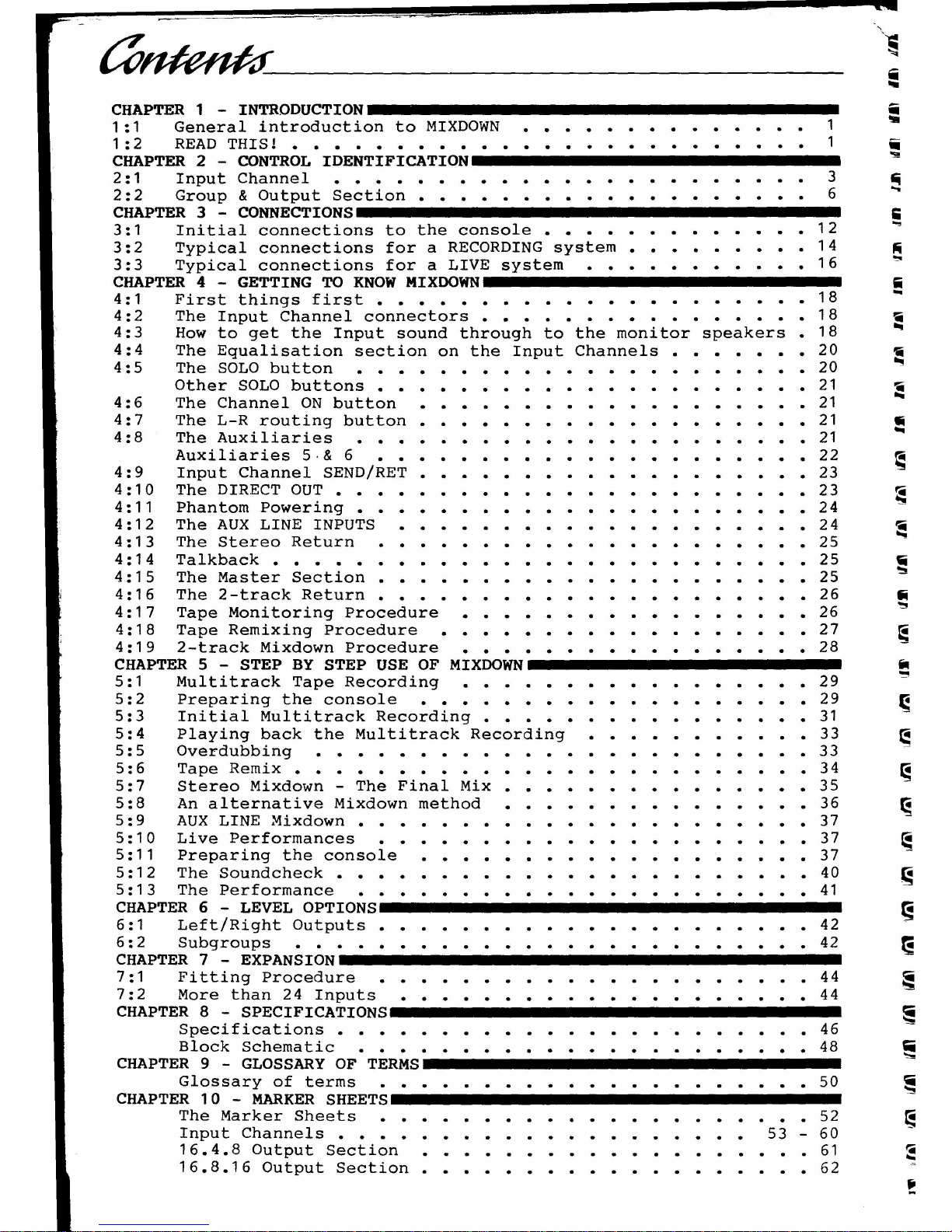
1:1 General introduction to MIXDOWN •••••••••••••• 1
1 :2 READ THIS! ••••••••••••••••••••••• 1
CHAPTER 2 - CONTROL IDENTIFICATION ••••••••••••••••••••••••••••••• _
2:1 Input Channel ••••••••••••••••••••• 3
2:2 Group & Output Section ••••••••••••••••• 6
CHAPTER 3 -
CONNECTIONS •••••••••••••••••••••••••••••••••••••••••• _
3:1 Initial connections to the console ••••••••••••• 12
3:2 Typical connections for a RECORDING system ••••••• 14
3:3 Typical connections for a LIVE system ••••••• 16
CHAPTER 4 - GETTING TO KNOW
MIXOOWN_•••••••••••••••••••••••••••••••
4:1 First things first ••••••••••••••• 18
4:2 The Input Channel connectors •••••••••• 18
4:3 How to get the Input sound through to the monitor speakers 18
4:4 The Equalisation section on the Input Channels. 20
4:5 The SOLO button •••••••••••••••••••• 20
Other SOLO buttons ••••••••••••••••••• 21
The Channel ON button ••••••••••• 21
The L-R routing button ••••••••••••••••• 21
The Auxiliaries •••••••••••• 21
Auxiliaries 5·& 6 ••••••••••••••••••••• 22
4:9 Input Channel SEND/RET ••••••••••••• 23
4:10 The DIRECT OUT ••••••••••••• 23
4:11 Phantom Powering •••••••••••••••••• 24
4:12 The AUX LINE INPUTS •••••••••••• 24
4:13 The Stereo Return ••••••••••• 25
4:14 Talkback •••••••••••••••••••• 25
4:15 The Master Section ••••••••••••••••••• 25
4:16 The 2-track Return ••••••••••••••••• 26
4:17 Tape Monitoring Procedure ••••••••••••• 26
4:18 Tape Remixing Procedure •••••••••••••••• 27
4:19 2-track Mixdown Procedure ••••••••••••••• 28
CHAPTER 5 - STEP BY STEP USE OF MIXOOWN •••••••••••••••••••••••••••••
5:1 Multitrack Tape Recording ••••••••••••• 29
5:2 Preparing the console ••••••••••••••••••• 29
5:3 Initial Multitrack Recording •••••••••••• 31
5:4 Playing back the Multitrack Recording ••••••••• 33
5:5 Overdubbing •••••••••••••••• 33
5:6 Tape Remix ••••••••••••••• 34
5:7 Stereo Mixdown - The Final Mix ••••••••••• 35
5:8 An alternative Mixdown method ••••••••••••• 36
5:9 AUX LINE Mixdown •••••••••••••••• 37
5:10 Live Performances ••••••••••••••••••• 37
5:11 Preparing the console ••••••••••••• 37
5:12 The Soundcheck ••••••••••••• 40
5:13 The Performance •••••••••••••• 41
CHAPTER 6 - LEVEL
OPTIONS •••••••••••••••••••••••••••••••••••••••••••
6:1 Left/Right Outputs ••••••••••••••••••• 42
6:2 Subgroups ••••••••••••• 42
CHAPTER 7 -
EXPANSION •••••••••••••••••••••••••••••••••••••••••••• _
7:1 Fitting Procedure ••••••••••••• 44
7:2 More than 24 Inputs •••••••••••• 44
CHAPTER 8 -
SPECIFICATIONS ••••••••••••••••••••••••••••••••••••• __
Specifications ••••••••••••••••••• 46
Block Schematic •••••••••••••••• 48
CHAPTER 9 - GLOSSARY OF
TERMS •••••••••••••••••••••••••••••••••••••••
Glossary of terms ••••••••••••••••• 50
CHAPTER 10 - MARKER
SHEETS_ •••• __ •••• __ ••••••••••••••••••••••••
The Marker Sheets ••••••••••••••• 52
Input Channels •••••••••• 53 - 60
16.4.8 Output Section ••••••••••• 61
16.8.16 Output Section .•••••••••••••• 62
••
'!II
'i
..•
;
...,
ii
...
"ii
•••
Iii
•••
~
-
Page 3
1:2 READ THIS
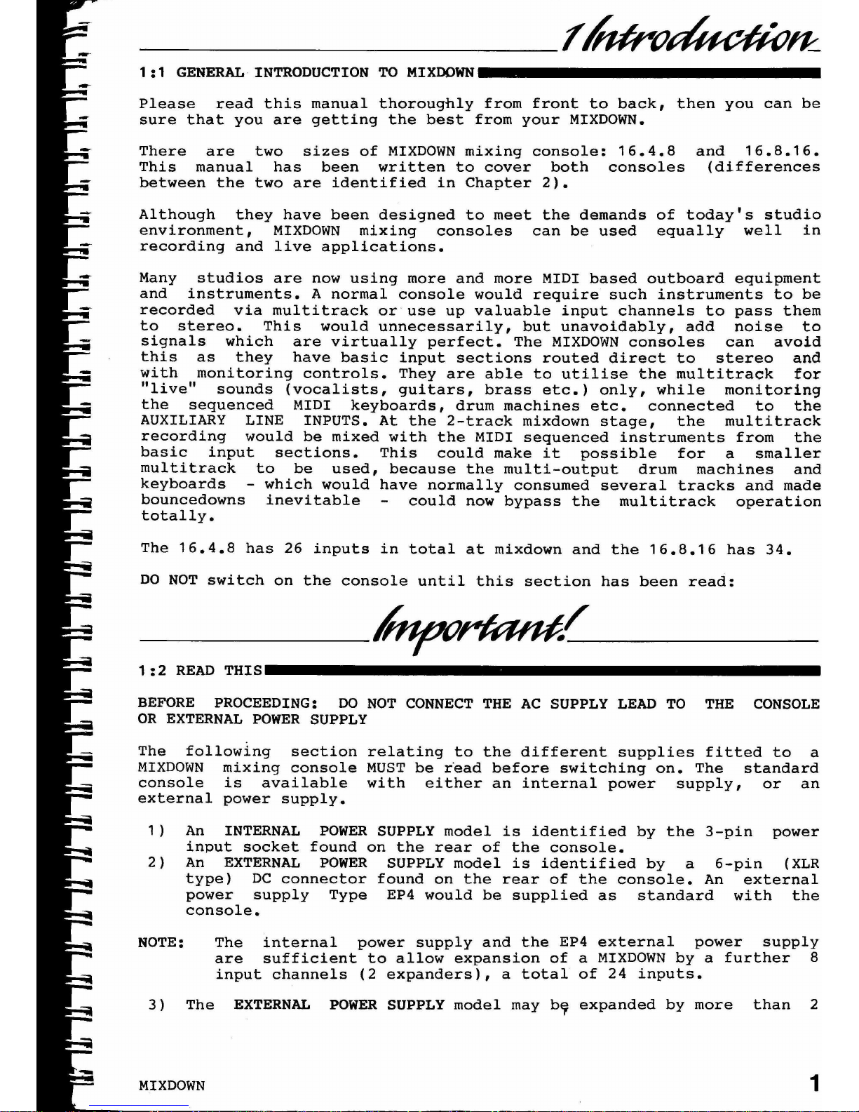
1:1 GENERAL INTRODUCTION TO MIXDOWN
1
and 16.8.16.
(differences
1) An INTERNAL POWER SUPPLY model is identified by the 3-pin power
input socket found on the rear of the console.
2) An EXTERNAL POWER SUPPLY model is identified by a 6-pin (XLR
type) DC connector found on the rear of the console. An external
power supply Type EP4 would be supplied as standard with the
console.
The 16.4.8 has 26 inputs in total at mixdown and the 16.8.16 has 34.
DO NOT switch on the console until this section has been read:
MIXDOWN
3) The EXTERNAL POWER SUPPLY model may by expanded by more than 2
Many studios are now using more and more MIDI based outboard equipment
and instruments. A normal console would require such instruments to be
recorded via multitrack or use up valuable input channels to pass them
to stereo. This would unnecessarily, but unavoidably, add noise to
signals which are virtually perfect. The MIXDOWN consoles can avoid
this as they have basic input sections routed direct to stereo and
with monitoring controls. They are able to utilise the multitrack for
"live" sounds (vocalists, guitars, brass etc.) only, while monitoring
the sequenced MIDI keyboards, drum machines etc. connected to the
AUXILIARY LINE INPUTS. At the 2-track mixdown stage, the multitrack
recording would be mixed with the MIDI sequenced instruments from the
basic input sections. This could make it possible for a smaller
multitrack to be used, because the multi-output drum machines and
keyboards - which would have normally consumed several tracks and made
bouncedowns inevitable could now bypass the multitrack operation
totally.
There are two sizes of MIXDOWN mixing console: 16.4.8
This manual has been written to cover both consoles
between the two are identified in Chapter 2).
Although they have been designed to meet the demands of today's studio
environment, MIXDOWN mixing consoles can be used equally well in
recording and live applications.
Please read this manual thoroughly from front to back, then you can be
sure that you are getting the best from your MIXDOWN.
NOTE: The internal power supply and the EP4 external power supply
are sufficient to allow expansion of a MIXDOWN by a further 8
input channels (2 expanders), a total of 24 inputs.
BEFORE PROCEEDING: DO NOT CONNECT THE AC SUPPLY LEAD TO THE CONSOLE
OR EXTERNAL POWER SUPPLY
The following section relating to the different supplies fitted to a
MIXDOWN mixing console MUST be rOeadbefore switching on. The standard
console is available with either an internal power supply, or an
external power supply.
Page 4
expanders if used with the more powerful EP3 rack mounted
external power supply (available separately).
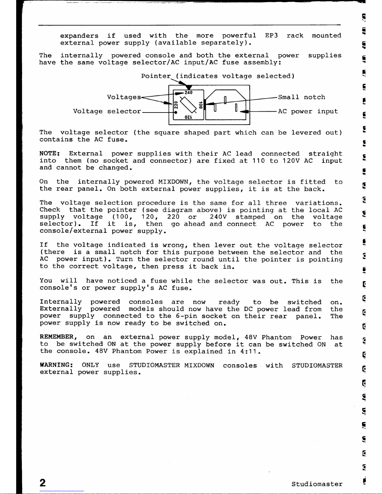
The internally powered console and both the external power supplies
i
have the same voltage selector/AC input/AC fuse assembly: ~
Pointer (indicates voltage selected)
Voltages
Voltage selector
240
=~-
N
=
N
=
oz~
Small notch
AC power input
The voltage selector (the square shaped part which can be levered out)
contains the AC fuse.
NOTE: External power supplies with their AC lead connected straight
into them (no socket and connector) are fixed at 110 to 120V AC input
and cannot be changed.
On the internally powered MIXDOWN, the voltage selector is fitted to
the rear panel. On both external power supplies, it is at the back.
The voltage selection procedure is the same for all three variations.
Check that the pointer (see diagram above) is pointing at the local AC
supply voltage (100, 120, 220 or 240V stamped on the voltage
selector). If it is, then go ahead and connect AC power to the
console/external power supply.
If the voltage indicated is wrong, then lever out the voltage selector
(there is a small notch for this purpose between the selector and the
AC power input). Turn the selector round until the pointer is pointing
to the correct voltage, then press it back in.
You will have noticed a fuse while the selector was out. This is
console's or power supply's AC fuse.
Internally powered consoles are now ready to be switched
Externally powered models should now have the DC power lead from
power supply connected to the 6-pin socket on their rear panel.
power supply is now ready to be switched on.
REMEMBER, on an external power supply model, 48V Phantom Power
to be switched ON at the power supply before it can be switched ON
the console. 48V Phantom Power is explained in 4:11.
the
on.
the
The
has
at
WARNING: ONLY use STUDIOMASTER MIXDOWN consoles with STUDIOMASTER
external power supplies •
2
Studiomaster
•
Page 5
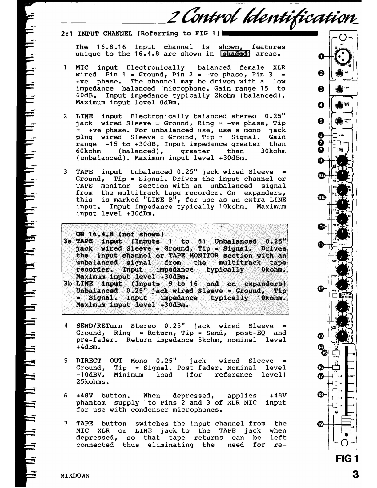
4 SEND/RETurn Stereo 0.25" jack wired Sleeve
=
Ground, Ring
=
Return, Tip
=
Send, post-EQ and
pre-fader. Return impedance 5kohm, nominal level
+4dBm.
3 TAPE input Unbalanced 0.25" jack wired Sleeve
=
Ground, Tip
=
Signal. Drives the input channel or
TAPE monitor section with an unbalanced signal
from the multitrack tape recorder. On expanders,
this is marked "LINE B", for use as an extra LINE
input. Input impedance typically 10kohm. Maximum
input level +30dBm.
o
FIG 1
3
the
when
left
re-
+48V
input
OUT Mono 0.25" jack wired Sleeve
=
Tip
=
Signal. Post fader. Nominal level
Minimum load (for reference level)
DIRECT
Ground,
-10dBV.
25kohms.
5
7 TAPE button switches the input channel from
MIC XLR or LINE jack to the TAPE jack
depressed, so that tape returns can be
connected thus eliminating the need for
6 +48V button. When depressed, applies
phantom supply 'to Pins 2 and 3 of XLR MIC
for use with condenser microphones.
The 16.8.16 input channel is shown, features
unique to the 16.4.8 are shown in
~Jtil<l.1
areas.
1 MIC input Electronically balanced female XLR
wired Pin 1=Ground, Pin 2
=
-ve phase, Pin 3
=
+ve phase. The channel may be driven with a low
impedance balanced microphone. Gain range 15 to
60dB. Input impedance typically 2kohm (balanced).
Maximum input level OdBm.
2 LINE input Electronically balanced stereo 0.25"
jack wired Sleeve
=
Ground, Ring
=
-ve phase, Tip
=
+ve phase. For unbalanced use, use a mono jack
plug wired Sleeve
=
Ground, Tip
=
Signal. Gain
range -15 to +30dB. Input impedance greater than
60kohm (balanced), greater than 30kohm
(unbalanced). Maximum input level +30dBm.
2:1 INPUT CHANNEL (Referring to FIG 1)
MIXDOWN
Page 6
input
when
left
re-
design
of a
control
separate
at the
a 2-pole
of a
control
separate
at the
2-pole
value
s the
TAPE ja(::k
can be
need for
attenuation to MIC
can be used to
which, after turning
is still too high to
semi-parametric
6 and on expanders)
the LINE jack when
input channel to be
low i ance balanced
LINE lev signal.
not shown)
(Inputs
the HIC
that t
thus eliminatin
remix.
(Inputs 9
m
HIC XLR
This allows
either a
or unbalanc~d
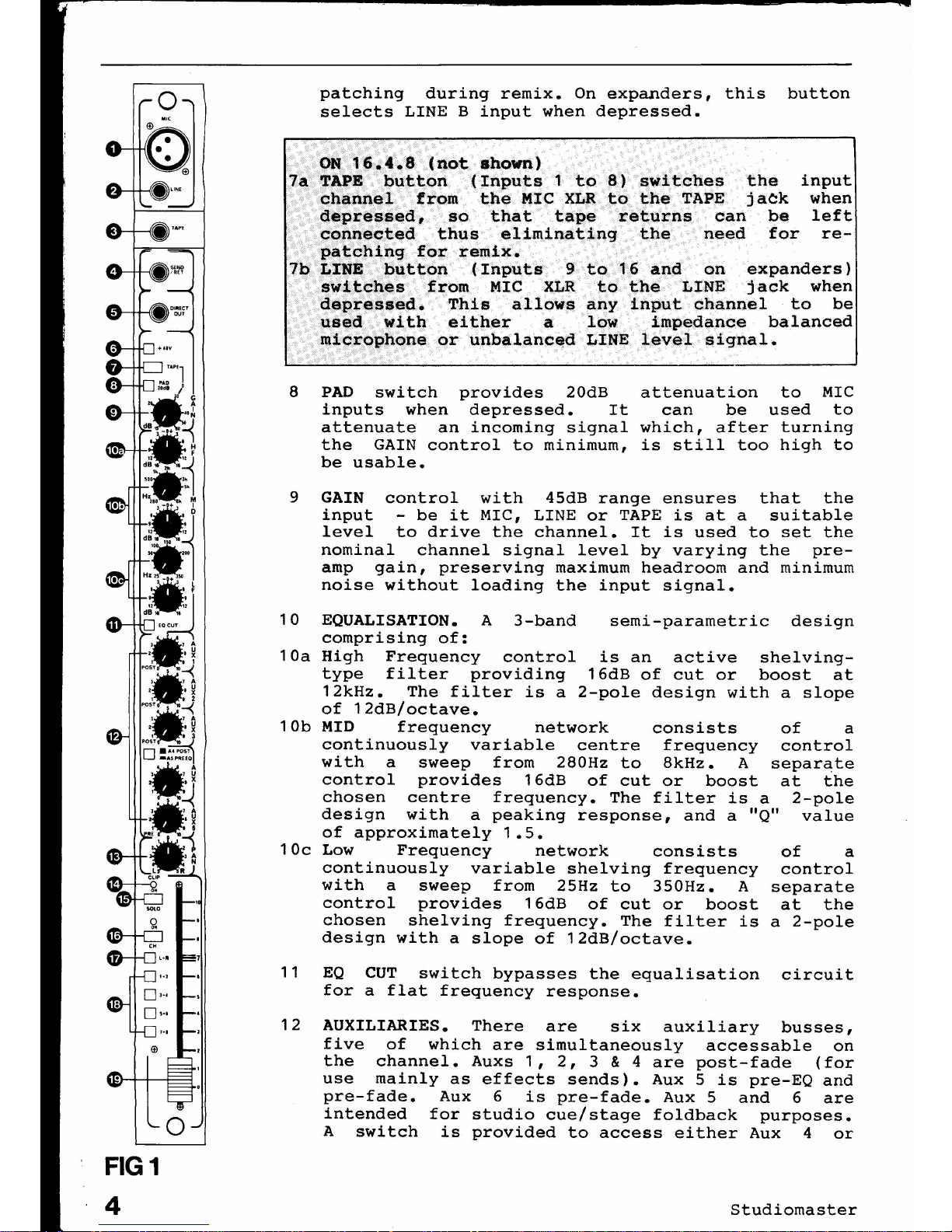
EQUALISATION. A 3-band
comprising of:
High Frequency control is an active shelving-
type filter providing 16dB of cut or boost at
12kHz. The filter is a 2-pole design with a slope
of 12dB/octave.
MID frequency network consists
continuously variable centre frequency
with a sweep from 280Hz to 8kHz. A
control provides 16dB of cut or boost
chosen centre frequency. The filter is a
design with a peaking response, and a "Q"
of approximately 1.5.
Low Frequency network consists
continuously variable shelving frequency
with a sweep from 25Hz to 350Hz. A
control provides 16dB of cut or boost
chosen shelving frequency. The filter is
design with a slope of 12dB/octave.
GAIN control with 45dB range ensures that the
input - be it MIC, LINE or TAPE is at a suitable
level to drive the channel. It is used to set the
nominal channel signal level by varying the pre-
amp gain, preserving maximum headroom and minimum
noise without loading the input signal.
PAD switch provides 20dB
inputs when depressed. It
attenuate an incoming signal
the GAIN control to minimum,
be usable.
Studiomaster
patching during remix. On expanders, this button
selects LINE B input when depressed.
8
9
12 AUXILIARIES. There are six auxiliary busses,
five of which are simultaneously accessable on
the channel. Auxs 1,2,3 & 4 are post-fade (for
use mainly as effects sends). Aux 5 is pre-EQ and
pre-fade. Aux 6 is pre-fade. Aux 5 and 6 are
intended for studio cue/stage foldback purposes.
A switch is provided to access either Aux 4 or
11 EQ CUT switch bypasses the equalisation circuit
for a flat frequency response.
10c
10a
10b
10
o
FIG 1
4
Page 7
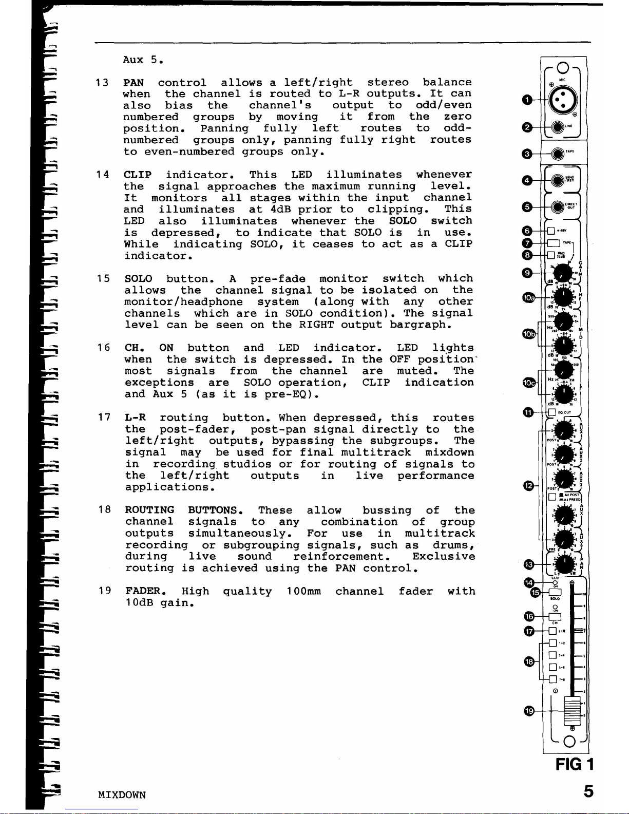
Aux 5.
13 PAN control allows a left/right stereo balance
when the channel is routed to L-R outputs. It can
also bias the channel's output to odd/even
numbered groups by moving it from the zero
position. Panning fully left routes to odd-
numbered groups only, panning fully right routes
to even-numbered groups only.
14 CLIP indicator. This LED illuminates whenever
the signal approaches the maximum running level.
It monitors all stages within the input channel
and illuminates at 4dB prior to clipping. This
LED also illuminates whenever the SOLO switch
is depressed, to indicate that SOLO is in use.
While indicating SOLO, it ceases to act as a CLIP
indicator.
15 SOLO button. A pre-fade monitor switch which
allows the channel signal to be isolated on the
monitor/headphone system (along with any other
channels which are in SOLO condition). The signal
level can be seen on the RIGHT output bargraph.
16 CH. ON
button and
LED
indicator.
LED
li9
hts
when
the switch is depressed. In
the
OFF position'
most
signals
from the channel
are muted.
The
exceptions
are SOLO operation,
CLIP indication
and Aux
5 (as it is pre-EQ)•
17 L-R routing button. When depressed, this routes
the post-fader, post-pan signal directly to the
left/right outputs, bypassing the subgroups. The
signal may be used for final multitrack mixdown
in recording studios or for routing of signals to
the left/right outputs in live performance
applications.
18 ROUTING BUTTONS. These allow bussing of the
channel signals to any combination of group
outputs simultaneously. For use in multitrack
recording or subgrouping signals, such as drums,
during live sound reinforcement. Exclusive
routing is achieved using the PAN control.
19 FADER. High quality 100mm channel fader with
10dB gain.
MIXDOWN
o
FIG 1
5
Page 8
Page 9
Page 10
Page 11
Page 12
Page 13
Page 14
Page 15
Page 16
Page 17
Page 18
Page 19
Page 20
Page 21
Page 22
Page 23
Page 24
Page 25
Page 26
Page 27
Page 28
Page 29
Page 30
Page 31
Page 32
Page 33
Page 34
Page 35
Page 36
Page 37
Page 38
Page 39
Page 40
Page 41
Page 42
Page 43
Page 44
Page 45
Page 46
Page 47
Page 48
Page 49
Page 50
Page 51
 Loading...