

Page 1
USER
GUIDE
Page 2
www.studiomaster.com
www.studiomaster.com
TAPER 2
CUE ACTIVE
POWER
MONO
0dB
-10
-15
-20
-30
-40
8
-5
11109876
0dB
-10
-15
-20
-30
-40
8
-5
0dB
-10
-15
-20
-30
-40
8
-5
0dB
-10
-15
-20
-30
-40
8
-5
0dB
-10
-15
-20
-30
-40
8
-5
54
OUTPUT
+10
+8
+6
+4
+2
0dB
-3
-6
-9
-12
-15
-20
OUTPUT
CUERL
XY
VCA XF1
0dB
-10
-15
-20
-30
-40
8
8
-5
+5
-5
-10
-15
-20
-30
0dB
8
+5
-5
-10
-15
-20
-30
0dB
8
+5
-5
-10
-15
-20
-30
0dB
-
+
LO
60Hz
-
+
AUX /
DSP
CUE
0 10
LO
60Hz
-
+
AUX /
DSP
CUE
0 10
LO
60Hz
-
+
AUX /
DSP
CUE
0 10
MIC
GAIN
80Hz
18dB/OCT
DSP
ON
VOCAL 1
SMALL REV
LARGE REV
ADT
CHORUS
ECHO
250Hz 6KHz
MID
-
+
INST VOCAL
1
HHI
I
1122KKHHz
z
-
+
MIC
GAIN
80Hz
18dB/OCT
10 55dB10 55dB
250Hz 6KHz
MID
-
+
INST VOCAL
HHI
I
1122KKHHz
z
-
+
MIC
GAIN
80Hz
18dB/OCT
10 55dB
250Hz 6KHz
MID
-
+
INST VOCAL
HHI
I
1122KKHHz
z
2 3DSP
BOOTH
PHONES
OUTPUT
TO BOOTH
MIC CUT
CUE
0dB +10dB
GAIN
HI
12KHz
MID
1.5KHz
LO
45Hz
0 10
CUE OUTPUT
0 10
GAIN
HI
12KHz
MID
1.5KHz
LO
45Hz
-
10 +10
-
10 +10
-
10 +10
-
10 +10
-
10 +10
-
10 +10
GAIN
HI
12KHz
MID
1KHz
LO
45Hz
GAIN
HI
12KHz
MID
1KHz
LO
45Hz
OUTPUT
Y
CUE
OUTPUT
X
CUE
OUTPUT
Y
CUE
OUTPUT
X
OUTPUT
PHONES
STEREO
MPX
STEREO
MPX
LINE A
LINE B
LINE A
LINE B
LEVEL
LEVEL
-36 +10
-36 +10
-36 +10
-36 +10
-36 +10
-36 +10
0dB +10dB0dB +10dB0dB +10dB
TAPER 1
VIDEO
A
B
OUTPUT
BALANCED
FOOTSWITCH
OUTPUT
BOOTH
LEFTRIGHT
RIGHT
PHONO
GND GND
LEFT
MONO
20Hz
18dB
PHONO
STUDIOMASTER MODEL - FUSION+
SERIAL
NUMBER
HERE
WARNING: THIS UNIT MUST BE EARTHED.
CAUTION: TO REDUCE THE RISK OF ELECTRIC SHOCK DO NOT
REMOVE COVER. NO USER SERVICEABLE PARTS INSIDE.
REFER SERVICING TO QUALIFIED SERVICE PERSONNEL.
TO REDUCE THE RISK OF FIRE OR ELECTRIC SHOCK DO NOT EXPOSE
THIS EQUIPMENT TO RAIN OR MOISTURE.
AVIS:RISQUE DE CHOC ELECTRIQUE. NE PAS OUVRIR.
CAUTION: TO REDUCE THE RISK OF FIRE REPLACE FUSE ONLYWITH
SAME TYPE AND RATING.
ATTENTION:UTILISER UN FUSIBLE DE RECHANGE DE MEME TYPE.
10-11 8-9 6-7 4-5
AUX
OUTPUT
INPUT
OUTPUT/
RECORD
LINE
LEFT
LINE
LEFT
LINE B
LEFT
LINE A
LEFT
LINE B
LEFT
LINE A
LEFT
VIDEO IN
A
A
VIDEO IN
B
B
VIDEO OUT
MONO OUTPUT
RIGHTRIGHT RIGHTRIGHT RIGHTRIGHT
RIGHT RIGHT
LEFT LEFT
RISK OF
ELECTRIC SHOCK
DO NOT OPEN
CAUTION
FUSE T160mAL 250V for 230V
FUSE T200mAL 250V for 115V
115/230V
50/60Hz 22 Watts Max
O
I
(-6dB)
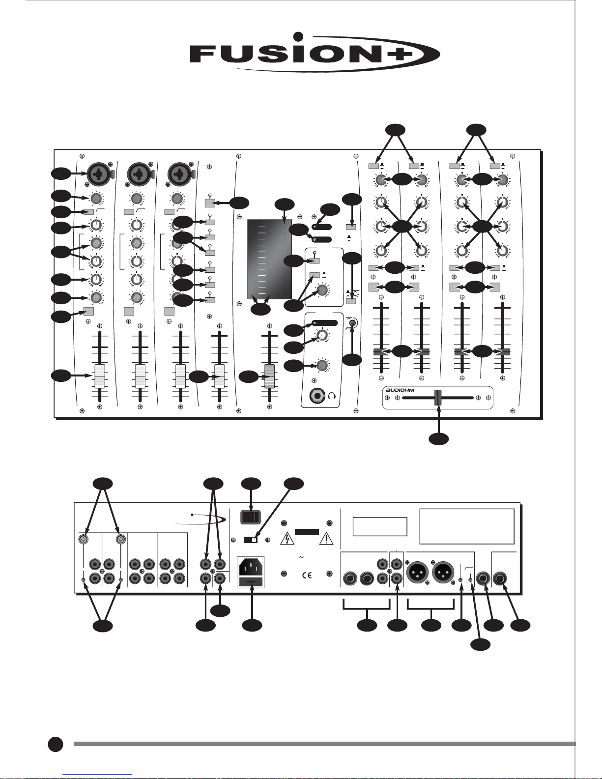
1
46 50
47
48 49
44
26
27
28
30
31
32
29
2542
22
10 16
2
3
4
6
5
7
9
43 45
8
11
14
15 21
13
12
17
20
19
18
33
34
35
36
37
38
41
40
39
37
51 52 54 56 57
55
53
Front panel
Rear panel
23
Page 3

1
EXPECT THE BEST
EXPECT THE BEST
English
Introduction 2
Safety Instructions 2
Applications 2
Channels 1,2, & 3 3
Stereo Channels 4/5 & 6/7 4
4
Stereo Channels 8/9 & 10/11
Cross-fader & Master Section 5
DSP Section 6
Rear Panel 7
Trouble Shooting 8
Internal Feature Options 8
Service Information 8
Glossary of Technical Terms 9-10
Suggested Set-ups 11-17
Wiring Connections 18
Block diagram 19
Technical Specification 20
Page 4
2
www.studiomaster.com
www.studiomaster.com
ORIGINAL
Introduction
The Fusion is a compact, versatile mixer packed with all the features the modern musician and DJ demands. As the
name suggests Fusion is the combination of three major sound elements. The first is professional mic channels with
smooth and musical E.Q. The second is a high quality DSP processor with studio quality effects to produce
stunning vocals. The third and the most unique feature is the music/D.J. inputs geared to modern club mixing.
Easy to use, incredibly flexible and backed up by quiet studio quality electronics. It can be used free standing or rack
mounted and the host of internal options make the Fusion adaptable to any situation.
Despite the sophistication behind the control panel, the Fusion is very easy to use, though to get the best from your
new purchase, we recommend you read this operator guide in full at least once before getting down to any serious
work. This opeartor guide contains important safety information as well as practical hints on operating a live sound
system.
Remove your Studiomaster Fusion from its packing and ensure that along with this operator guide you have an AC
power cord/mains lead and a warranty card. Retain the packing carton in the eventuality that the unit needs to be
returned for service or repair and please complete and return your warranty card. Returning the completed warranty
card does not diminish your statutory rights in any way.
WARNING: THIS APPARATUS MUST BE EARTHED (GROUNDED)
1. Make sure the Voltage Selector is set to your local supply Voltage. For supplies between 220 and 240 Volts
use the 230 position. For supplies between 110 and 120 Volts use the 115 position.
2. Only use the A.C. power cord/mains lead supplied with the product.
Replace if it becomes damaged in any way.
3. Never operate without, or remove, the safety ground (earth) from the A.C. power cord/mains lead.
4. Do not attempt to remove screws or panels on your Fusion. There are no user serviceable parts inside.
5. Do not operate the unit next to heat sources such as radiators.
6. The unit should not be operated or stored near rain or moisture.
7. Do not allow objects or liquid to enter the unit.
8. This equipment must not be exposed to dripping or splashing and no objects filled with liquids should be placed on
top of it.
9. Write the serial number in the box provided in the Service Information (page 8) for future reference.
10. If the unit gets damaged, has been dropped or appears to have developed a fault refer to the Service
Information section for details.
DJs - 4 full featured stereo inputs, 2 with -36dB "kill" facility, and switchable to vinyl (RIAA). Assignable VCA cross fader
with fully adjustable tapers producing smooth mixes.
Karaoke - A total of 3 full featured mic channels.
The onboard DSP digital reverb/delay enhance vocal performances and 4 stereo channels - 2 for Karaoke machines
and 2 for background/ back up CD players.
Solo / Duo Performer / Live Music - The 3 professional mic channels can be used for vocals or instruments, the
4 stereo inputs can be used for drum machines, keyboards, etc or CD/mini disk play back. Easy to use onboard
digital reverb for the perfect vocal sound.
Club mixer
-
The 4 stereo channels have all the latest features a DJ needs, including -36dB "kill" controls, with a
flexible Booth output (with selectable mic mute), the VCA cross fader is internally adjustable for cross mix, beat mix,
and cut mix. A separate CUE bus bargraph makes beat and level matching with the main outputs easy.
Night club/entertainment venue - The flexible input arrangement can accommodate all types of performer. Small
bands, background music, disco or a simple announcement/PA system can all be easily handled by the Fusion.
Install - The main outputs are on balanced XLR connectors with level adjustment, mic inputs are on the front panel for
easy access. A 20Hz, 18dB/Octave filter on the main outputs reduces out of band signal (from CDs, records and
instruments) reducing power loss and promoting tighter bass in the sound system.
Read the operator guide
Unpacking
Safety instructions
Applications
(see set-up diagrams page A )
Page 5
WHAT HAPPENS IF I PRESS THIS?
CONTROLS & FEATURES
3
EXPECT THE BEST
EXPECT THE BEST
8
+5
-5
-10
-15
-20
-30
0dB
-
+
LO
60Hz
-
+
AUX /
DSP
CUE
0 10
MIC
GAIN
80Hz
18dB/OCT
250Hz 6KHz
MID
-
+
INST VOCAL
1
HHI
I
1122KKHHz
z
10 55dB
HI
12KHz
1
2
3
4
5
6
7
8
9
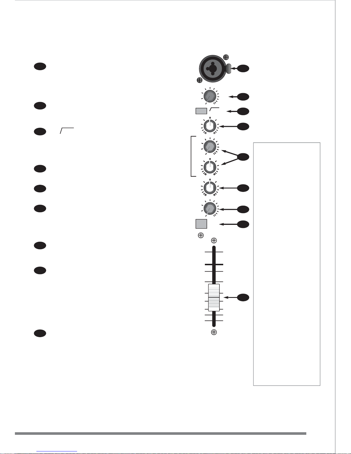
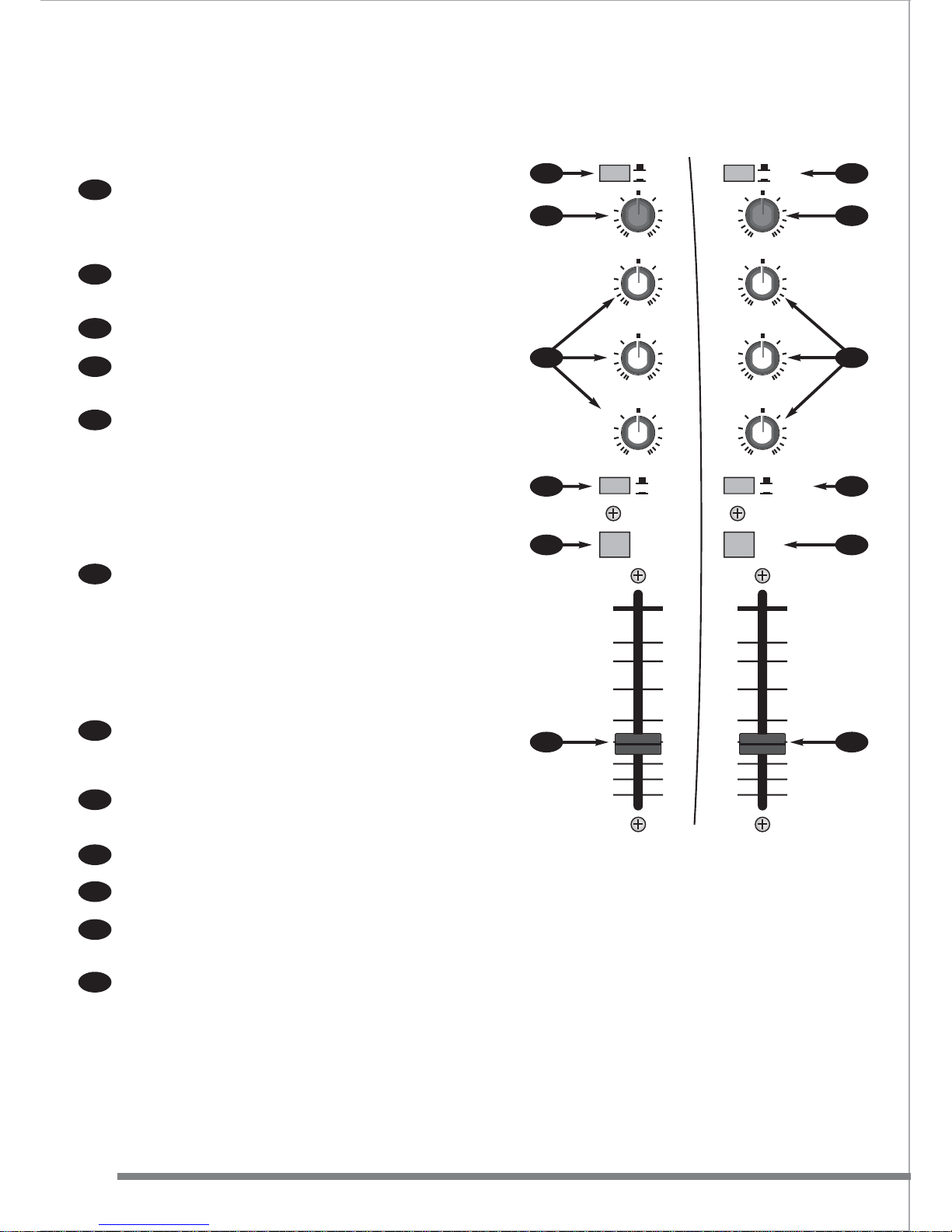
CHANNELS 1, 2 & 3
Channels 1- 3 use a combination XLR and 1/4” jack connector.
You can use a microphone fitted with a 1/4” jack or, for best
results, use a balanced microphone with a 3-pin XLR
connector. The design of the circuitry allows the jack input to
be used to connect electric guitars, keyboards and most line
level equipment.
The Gain control is used to match the incoming signal level to
the internal operating levels of the Fusion. This ensures the
best performance, reduces noise and avoids distortion. Typical
settings for microphones are marked on the front panel.
The 80Hz button operates a high pass filter (HPF) which cuts
out just the very low frequencies, reducing handling noise,
stage rumble and wind noise. It should be used with all mics
and instruments - except those with significant bass content.
The overall mix will sound cleaner and minimise wasted
amplifier power.
The HI control cuts or boosts the high frequency (or treble)
element of the sound. In the centre (12 o’clock) position, the
sound is unaffected. The HI control works at 12kHz.
The LO control operates in the same way as the HI control
except that it affects the low frequency (bass) part of the
sound. The LO control operates at 60Hz.
The MID consists of two controls. The lower control operates
in the same way as the HI & LO. The upper control (the
‘sweep’) adjusts the frequency at which it operates. Typical
settings suitable for microphones and instruments are marked
on the front panel. The MID frequency sweep control adjusts
between 250Hz and 6kHz.
AUX/DSP sends some of the signal from the channel to the
on-board effects processor and to the AUX OUTPUT jack on
the rear panel - for external effects processing. The signal for
the AUX/DSP control is controlled by the fader.
CUE routes the channel signal to the CUE led meter and the
PHONES/BOOTH outputs if selected. This has no effect on the
signal going to the Left/Right output.
Note - when any CUE button is pressed the signal source
displayed on the L-R meters changes from post output fader to
pre-fader. This means that instead of the meters showing the
actual signal level leaving the Fusion, it shows the mix of
signals before the master fader. This is very useful as it allows
a comparison between the cue’d bargraph signal and the mix
(output) signal.
The fader adjusts the level from the channel to the main
output. The fader acts as a volume control for each channel.
They join all the various sounds together creating a blend or
‘mix’ of sounds. The long, smooth faders make small
adjustments easy as well as giving a visual representation of
sound levels.
In use, aim to set the fader at the 0dB position. It can then be
raised or lowered to adjust the sound (mix).
9
8
7
5
4
2
1
3
6
Tone controls
Hi, Mid & Lo
The controls marked HI, MID
and LO are very useful for
changing the characteristics or
tone of the sound. For
simplicity or for new users set
these controls to the centre
position, which effectively
turns off or bypasses the tone
control section and you will
not need to worry about these
controls until you feel more
confident.
However, to get the best out
of your audio system or if you
just want to experiment read
on.....
Adding a little HI on
CD/Cassettes can add
brightness to the sound. For
microphones increasing the
MID ranges tends to ‘lift’ the
vocal adding clarity to the
voice.
For CD/cassettes adding LO
makes the bass section of
music more prominent. For
microphones doing the
opposite and removing a little
bass helps stop the ‘popping’
or ‘boomy’ sound often
apparent when a microphone
is used too close to the
mouth.
For best results with
microphones/CD/cassettes,
don’t be over enthusiastic with
the tone controls as this can
make the sound un-natural.
With guitars or other
instruments more extreme
tone settings can be used to
create more of a sound effect.
Page 6
WHAT HAPPENS IF I PRESS THIS?
CONTROLS & FEATURES
4
www.studiomaster.com
www.studiomaster.com
9876
0dB
-10
-15
-20
-30
-40
8
-5
0dB
-10
-15
-20
-30
-40
8
-5
GAIN
HI
12KHz
MID
1.5KHz
LO
45Hz
-
10 +10
-
10 +10
-
10 +10
GAIN
HI
12KHz
MID
1KHz
LO
45Hz
CUE
OUTPUT
X
CUE
OUTPUT
Y
STEREO
MPX
LINE A
LINE B
-36 +10
-36 +10
-36 +10
0dB +10dB0dB +10dB
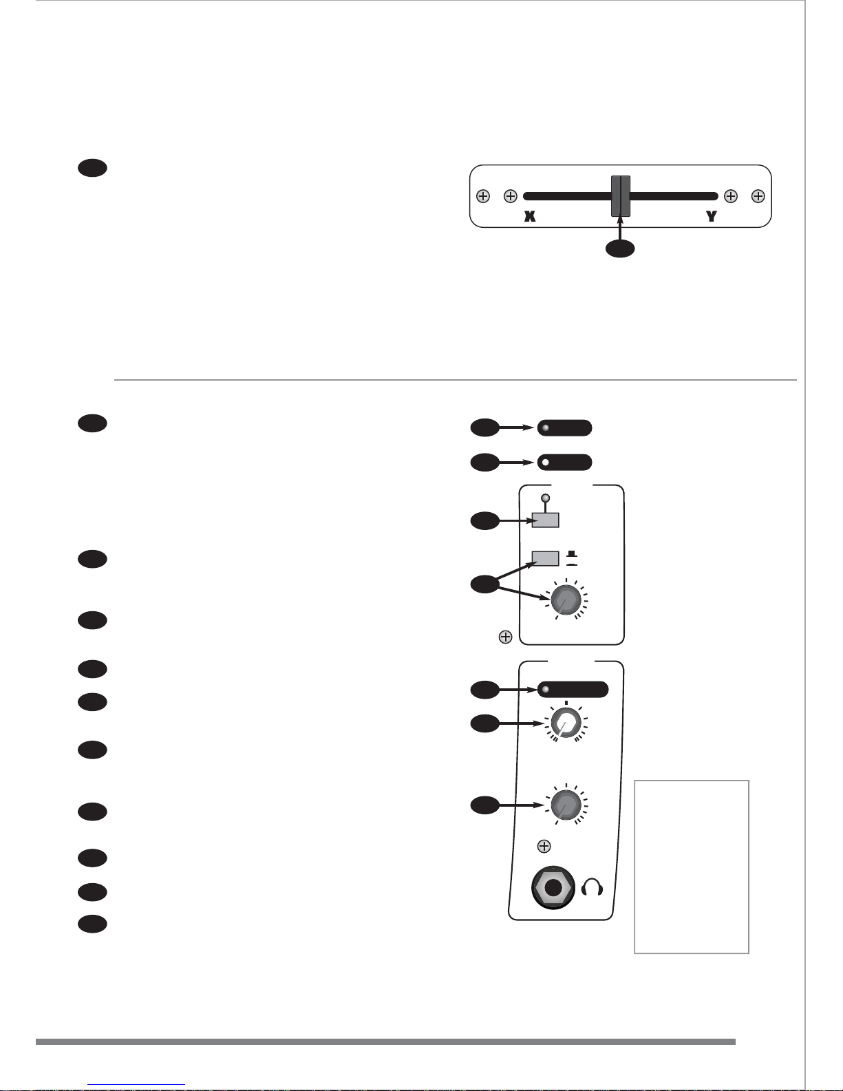
STEREO CHANNELS 4/5 & 6/7
The first two stereo channels have two sets of input connectors with a
selector switch (LINE A/LINE B). This means that two stereo signals
can be permanently connected and selected using the switch on the
front panel. Perhaps a CD and a minidisc player or any two sources
that never need to be operating at the same time.
The Gain control is used to match the incoming signal level to the
internal operating levels of the Fusion. This ensures the best
performance, reduces noise and avoids distortion.
The EQ (equalisation) is a three-band design +/-10dB at 12kHz (HI),
1.5kHz (MID) & 45Hz (LO).
Both channels can be assigned directly to the main output or to the
VCA cross-fader. Channel 4/5 routes the signal to "X" or left side of
the cross fader and channel 6/7 to "Y" or right side of the cross fader .
CUE routes the channel signal to the CUE led meter and the
PHONES/BOOTH outputs. This has no effect on the signal going to
the Left/Right output.
Note - when any CUE button is pressed the signal source displayed
on the meters changes from the post output fader to pre-fader. This
means that instead of the meters showing the actual signal level
leaving the Fusion it shows the mix of signals before the master fader.
This is very useful as it allows a comparison between the cue
bargraphs signal and the mix (output) signal.
The fader adjusts the level from the channel to the main output. For
normal operation always operate these faders at the top (0dB)
position. This gives the best audio performance and gives maximum
fader travel for smooth fade outs.
STEREO CHANNELS 8/9 & 10/11
These channels have a rear mounted switch ("PHONO") (44) allowing
record decks to be connected.
The front panel MPX/STEREO switch allows the use of "multiplex"
type CD' s for karaoke use. When a "mutiplex CD" is used and the
switch is in MPX position, the vocals are removed, leaving just the
backing track for singing to.
The Gain control is used to match the incoming signal level to the
internal operating levels of the Fusion. This ensures the best
performance, reduces noise and avoids distortion.
EQ is tailored to the creative DJ with up to 36dB of cut and 10dB of
boost. Frequencies are set at 12kHz (HI), 1kHz (MID) & 45Hz (LO).
Both channels can be assigned directly to the main output or to the
VCA cross-fader.
CUE routes the channel signal to the CUE led meter and the
PHONES/BOOTH outputs if selected. This has no effect on the signal
going to the Left/Right output.
The fader adjusts the level from the channel to the main output. For
normal operation always operate these faders at the top (0dB)
position. This gives the best audio performance and gives maximum
fader travel for smooth fade outs.
Connectors for stereo channels are all RCA/phono type.
10
11
12
13
14
15
16
17
18
19
20
21
10
11
12
13
14
15
16
17
18
19
20
21
Page 7
WHAT HAPPENS IF I PRESS THIS?
CONTROLS & FEATURES
5
EXPECT THE BEST
EXPECT THE BEST
VCA XF1
22
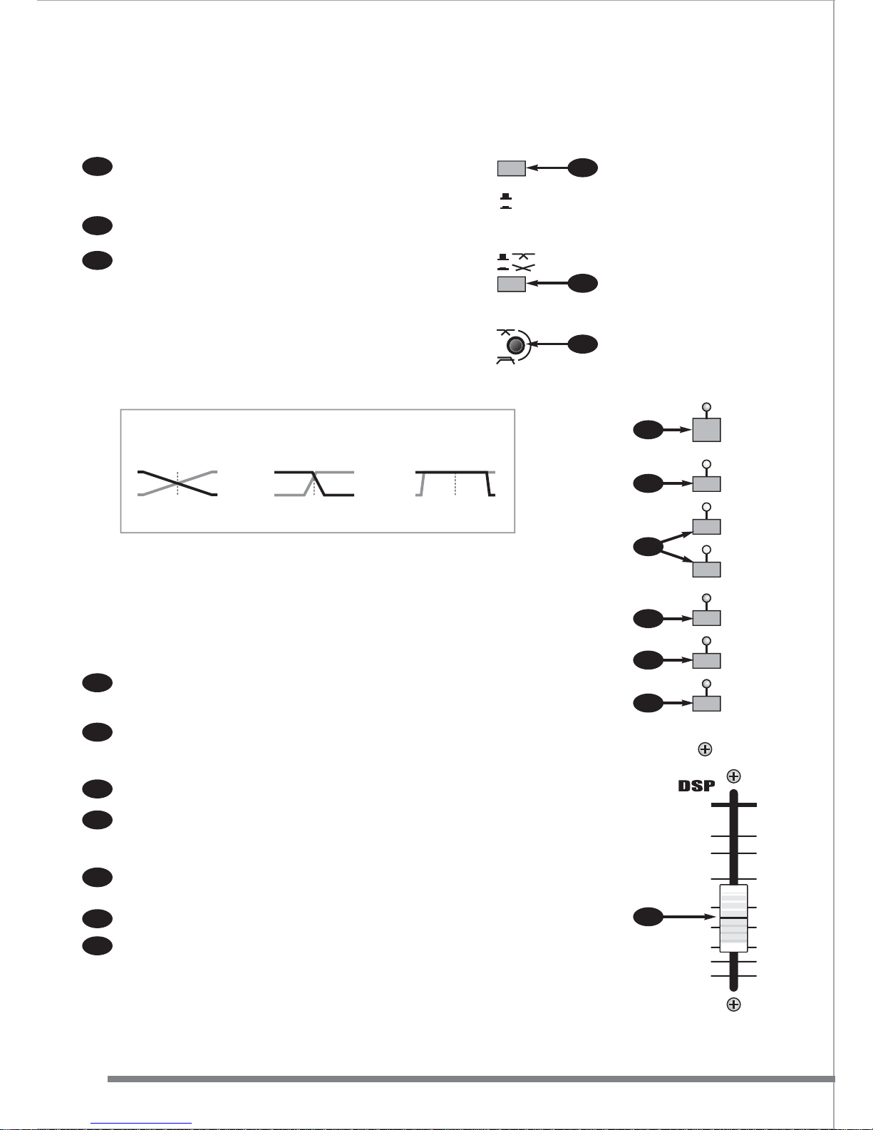
CROSS-F ADER
The cross-fader can be used simply to fade from one stereo
channel to another or creatively by the DJ. Two ‘TAPER’ controls
(34 & 35) in the master section of the Fusion allow a number of
effects and mixing tricks. The signal to the cross-fader is assigned
from the stereo channels using the “X” and “Y” switches (13 & 19).
Experimentation is recommended.
Note: this cross-fader is easily removable using the two screws on
the panel. Should your cross-fader become worn or damaged it
can be replaced without lengthy downtime. Contact your dealer for
information about obtaining replacement cross-faders.
The Fusion cross-fader circuit uses VCAs (voltage controlled
amplifiers) to eliminate the operational noise and intermittent
operation that can occur with ‘conventional’ cross-faders after
extended use.
MASTER SECTION
Two 12 segment, 3 colour LED meters display the main Left/Right
output levels.
Note - when any CUE button is pressed the signal source
displayed on the meters changes from the post output fader to
pre-fader. This means that instead of the meters showing the
actual signal level leaving the Fusion it shows the mix of signals
before the output fader. This is very useful as it allows a
comparison between the cue bargraphs signal and the mix
(output) signal.
The Cue meter displays the level of all signals assigned to the cue
bus. It displays cue’d signals from mic channels and the right
channel of the cue’d signal from stereo channels. This allows beat
matching with the right output meter next to it.
The OUTPUT fader is the master volume control, like the volume
control on a HI-FI. Always lower the fader to ‘ ’ before turning on.
This will avoid any ‘ surprises’ from CDs playing or mics left on!
The POWER LED lights when the Fusion is connected to the AC
power supply and switched on.
The MONO LED lights when the MONO switch (on the back
panel) has been selected. The main left-right output signal will
now be in mono.
When the “OUTPU T TO BOOTH MIC CUT” switch is selected, the
associated LED illuminates and all microphone channels are
disconnected from the BOOTH output mix. This helps to avoid
feedback in the DJ booth. Note: the main mix is unchanged.
OUTPUT/PHONES gives you the choice of sending either the
PHONES mix or the main Output mix to the BOOTH output. The
LEVEL control adjusts the volume of the BOOTH output.
The CUE ACTIVE LED illuminates if any CUE buttons are
activated.
CUE/OUTPUT allows a mix between signals being “CUE’d” an d
the main output to be heard on the phones output.
LEVEL adjusts the volume of the PHONES output.
22
23
24
25
26
27
28
30
29
31
32
CUE ACTIVE
POWER
MONO
BOOTH
PHONES
OUTPUT
TO BOOTH
MIC CUT
0 10
CUE OUTPUT
0 10
OUTPUT
PHONES
LEVEL
LEVEL
26
27
28
30
31
32
29
Headphones
The best
headphones to use
with Fusion are
studio grade 200 400 ohm types,
although most types
can be used but may
not sound as loud.
Headphones are
used mainly for
cueing
8
Page 8
WHAT HAPPENS IF I PRESS THIS?
CONTROLS & FEATURES
6
www.studiomaster.com
www.studiomaster.com
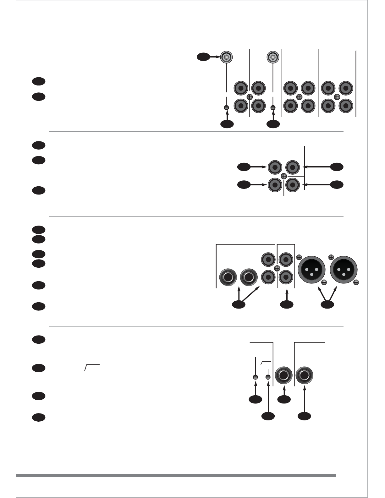
The VIDEO A/B switch allows the video outputs of two video
players to be connected to the Fusion and selected from the
front panel. The VIDEO output (on the rear panel) can then be
connected to a single video monitor.
The TAPER 1 switch sets the cross-fader slopes. It switches
between a gradual or quick fade.
The TAPER 2 control adjusts the position on the fader at which
the fade happens. In the clockwise position the signal is faded
to zero at the end of the cross-faders travel, like a
“conventional” cross-fader. In the anticlockwise position the
signal is fully faded out in the centre.
Positions inbetween set the ‘fade out’ anywhere between 50%
and 100% of cross-fader travel.
For the classic ‘Cross Mix’, select the Taper 1 switch ‘in’ and
the Taper 2 control fully clockwise.
DSP SECTION
DSP ON switches the effects processor on or off. When the
effects processor is on, the LED will light. This function is also
available via footswitch control, see rear panel, 57.
VOCAL 1 : a combination of reverb and delay developed by
Studiomaster and the choice of many professional performers
world wide.
SMALL & LARGE REVERB : good quality reverbs, great for ballads.
ADT : automatic double tracking : a technique used in the 60s
which adds a small delay to the voice giving a thicker, more
powerful vocal.
CHORUS : a modern, subtle effect that works well with voices
in the upper range.
ECHO : a classic rock & roll delay with several repeats.
THE DSP fader sets the amount of effect going to
the main output. Used around the mid-way position, the sound
effect will tend to be more subtle. With the fader at the top
(0dB) position the effect becomes more prominent.
36
38
37
39
40
41
42
33
34
35
TAPER 2
TAPER 1
0dB
-10
-15
-20
-30
-40
8
-5
DSP
ON
VOCAL 1
SMALL REV
LARGE REV
ADT
CHORUS
ECHO
HI
12KHz
HI
12KHz
36
38
41
40
39
37
42
34
35
VIDEO
A
B
VCA Cross-fader
Typical styles available
CROSS-MIX BEAT -MIX CUT-MIX
33
Taper 1 ‘in’
Taper 2 ‘clockwise’
Taper 1 ‘out’
Taper 2 ‘anticlockwise’
Taper 1 ‘out’
Taper 2 ‘clockwise’
Page 9
WHAT HAPPENS IF I PRESS THIS?
CONTROLS & FEATURES
7
EXPECT THE BEST
EXPECT THE BEST
REAR P ANEL
Connectors for stereo channels are all RCA/phono type.
Stereo channels 8-9 & 10-11 are fitted with ‘ground’ terminals for
record decks.
The recessed PHONO switches activate internal RIAA circuitry
making these inputs suitable for record decks. (channels 8-9 & 10-11)
Stereo channels 4-5 & 6-7 have dual input connectors selectable by
the front panel switch (10).
VIDEO A & B IN - Connect the composite video output of each
video/karaoke machine here.
VIDEO OUT - Connect to a composite video monitor.
Note: these sockets (45 & 46) do not connect to the audio signal
within the Fusion and should be used only for composite video
signals.
MONO OUTPUT provides a line level (-6dB) mono sum of the main
output. This can be used for additional mono amplifiers (zone or sub
bass) or used to connect to lighting controllers.
POWER ON/OFF switch turns the Fusion on and off.
The Voltage selector allows the Fusion to operate on either 115 or
230 Volt AC supplies.
The AC power connector also contains the internal A.C. power fuse.
BOOTH OUTPUT is available on both 1/4” jacks and RCA/phono
connectors. These outputs should be connected to the input of the
amplifier powering the booth monitor system.
OUTPUT/RECORD provide the main mix on RCA/phono connectors.
They can be used to provide a signal to the main amplifier/speaker
system or for recording.
The 3 pin XLRs provide the main mix with a balanced signal to
drive a professional amplifier/speaker system.
The recessed MONO switch sums the main Left & Right outputs
together and sends a mono signal to both the Left and the Right
output XLRs. When MONO is selected the MONO LED on the front
panel will light.
The recessed 20Hz switch activates a 20Hz high pass filter on the
outputs of the Fusion. This stops excessively low frequencies from
reaching the amplifier/speaker system and possibly causing damage.
It is recommended that this filter is always used.
The AUX OUTPUT 1/4” jack takes the signal from the AUX/DSP
controls on the front panel and sends them to an external effects
processor if required.
The FOOTSWITCH jack turns the effects processor on and off.
The footswitch socket works with a LATCHING type footswitch
(not supplied).
43
44
45
46
47
48
49
50
51
52
53
54
55
56
57
PHONO
GND GND
PHONO
1
0-11 8
-9 6-7 4-5
LINE
LEFT
LINE
LEFT
LINE B
LEFT
LINE A
LEFT
LINE B
LEFT
LINE A
LEFT
RIGHTRIGHT RIGHTRIGHT RIGHTRIGHT
VIDEO IN
A
A
VIDEO IN
B
B
VIDEO OUT
MONO OUTPUT
(-6dB)
FOOTSWITCH
MONO
20Hz
18dB
AUX
OUTPUT
43
4444
47
54
55
56
57
46
45
45
OUTPUT
BALANCED
OUTPUT
BOOTH
LEFTRIGHT
RIGHT LEFT
SAME TYPE AND RATING.
ATTENTION: UTILISER UN F
OUTPUT/
RECORD
RIGHT RIGHT
LEFT LEFT
51 5352
Page 10

8
www.studiomaster.com
www.studiomaster.com
If you have a problem with your Studiomaster product or think it has developed a fault you should first carefully check the
Trouble Shooting section in this guide. If this does not solve the problem or if the product is physically damaged, contact
your local dealer or distributor for service details.
Should it be recommended you return the product to your nearest Studiomaster Service Centre you must first contact them.
You will be asked for the product type and serial number. You will then be given a Returns Authorisation (RA) number.
Pack the unit in its original carton to protect it from shipping damage.
You must have the Return Authorisation number clearly marked on the outside of the carton or we may refuse the
delivery. Studiomaster cannot be held responsible for damage resulting from the equipment being packed
incorrectly.
Label the equipment clearly with your name and address and include a clear description of the fault.
Please write your Serial number here for future reference....
No power on LED.....
Check A.C. power cord/mains lead is connected to wall supply and switched on.
Check A.C. power cord/mains lead is fully pushed into Fusion rear panel socket.
Check Fusion is switched on.
Check correct voltage is selected.
Check Fusion A.C. fuse (on rear panel, inside the power inlet connector). Always replace with the same type and rating.
UK only - Check fuse in ‘mains’ plug
No sound.....
Check for a signal on the meters.
Check the amplifier and speaker system is connected and switched on.
Use headphones to check the output of the Fusion.
Check that the fader of the channel being used and the OUTPUT fader are raised to ‘normal’ positions (0dB).
Check the sound source - is it on?
Headphones distorting.....
Is the phones level set too high?
Are headphones being used with too low an impedance? 150-200 ohm types will give best performance, 32-50 ohm
types can be used but may give lower maximum sound level.
Mic channel:
1. Aux/DSP send can be configured
pre, post fader and pre E.Q.
Factory set: post fader.
Access: internal jumper - HDR2 on
mic channels
Stereo channel 8/9-10/11:
1. Standard RIAA or IEC addendum.
Factory set to IEC - Adds a 20Hz
high pass filter to the standard RIAA
equalisation.
Access: internal jumper - HDR2
(channel 8-9) and HDR4 (channel
10-11) on input connector PCB in
base.
Output section:
1. LED metering- VU or PPM.
Factory set: VU.
Access: internal jumper - HDR1 on
each meter PCB.
2. Output level- 0VU = +10dBu or +4dBu
Factory set: +10dBu.
Access: internal jumper - HDR1 on
output PCB.
3. Booth output signal select:
Follow main output, always mono,
always stereo.
Factory set: Follow main output.
Access: internal jumper - HDR1 on
output PCB
Service Information
Trouble Shooting
Internal Feature Options
The following options are accessed by removing the front panel.
Only qualified service personnel should undertake this work.
Page 11

TELL ME WHAT IT MEANS
GLOSSARY
9
EXPECT THE BEST
EXPECT THE BEST
Glossary
AC POWER SUPPL Y
Local electrical supply
ASSIGN
To switch or route a signal to a specific signal path.
ATTENU A TE
To reduce or make quieter.
AUX/AUXILIAR Y
An additional means of sending a signal to external equipment
generally without affecting what is going on in the main mix.
BALANCE
The relative levels of signals. Also refers to the left/right position in
a stereo mix.
BALANCED
A 3 wire system for connecting audio which has 2 wires for the
audio (HOT and COLD) and a totally seperate connection for the
screen. Balanced circuitry is widely used in audio equipment from
inexpensive dynamic microphones to top quality studio devices.
The balanced system is used as it cancels interference in the
connecting cables resulting in a cleaner signal
BANDWIDTH
In audio terms the bandwidth is the range of frequencies that will
pass through a piece of equipment.
BOOTH
A seperate area or enclosure typically used by DJs. Depending on
the type of venue, the sound mix may be different to that in the
dance area, so the booth helps to isolate what the DJ and audience
hear.
BUS
A common conductor that carries a signal, or number of signals,
through a mixing console.
COLD
The negative phase of a signal. With a simple unbalanced two wire
signal one wire is positive (HOT) and the other is negative (COLD).
COMPRESSOR
An electronic device used to stop the level of a sound from
increasing above a set threshold point. A compressor can also be
used to keep signal levels from overloading the input of a piece of
equipment.
CLIPPING
Distortion caused by a signal exceeding the maximum level that the
equipment can accommodate.
CUE
A button that allows the operator to monitor signals within the unit
independently of the main mix.
CUEING
Makes it possible to hear the sound from an input before adding it
to the mix.
D.I.
Direct Injection. Often a small ‘D.I. box’ is used to send a signal
directly from a guitar or bass into the mixer to avoid the need for a
microphone to capture the sound.
DECIBEL (dB)
A logarithmic ratio used to represent voltage or power gain. The
reference to which the ratio is made is usually stated. 0dB means
that the input and outputs are at the same level.
DECIBEL (dBA)
A logarithmic measure of sound intensity. In this case 0dB is the
threshold of human hearing. 100+ dBA is ‘loud’. Long term
exposure to high level sound can ultimately cause hearing damage.
Normal speech, such as in a quiet office is typically around 60dBA.
120dBA is normally quoted as the threshold of pain.
DELAY
Nowadays a delay or DDL (Digital Delay Line) is an electronic
effects processor which samples a short sound and replays it back
a short time later to give an echo effect.
DETENT
A soft ‘click’ in the travel of a rotary control usually indicating the
centre point.
DRY
A signal which has not been processed by an effects unit.
EFFECTS SENDS
Any outputs from a channel or console that can be connected to
external equipment for extra sound processing. Usually effects
sends are post fade so any level changes to the main signal also
adjust the signal sent for processing.
ECHO
The effect produced when sound is reflected off hard surfaces.
Often reproduced artificially using electronic equipment (See
DELAY).
E.I.N.
Equivalent Input Noise. A technical specification used to measure
the noise of a gain stage, typically a microphone pre amplifier.
EFFECTS
Any device that alters a sound. Can be anything from a simple foot
pedal to a sophisticated professional studio effects processor
EQUALISA TION (EQ)
Tone controls. Also in the case of analogue tape recording and vinyl
records, frequency dependent gain used to correct limitations of the
recording/playback process.
F ADER
Volume control, often a linear or slider type volume control.
FEEDBACK
The deafening squealing sound produced when a microphone picks
up its own amplified sound from a loudspeaker.
F .O .H.
Front of House. The speaker system which is used to project the
sound from the stage to the audience. It is also used to describe
the position, in front of the stage, where the main mixing console is
situated.
FLAT (EQ)
When the signal has not been adjusted using the equaliser (EQ)
controls.
FOLDBACK
Sound which is sent from the main mixing position back to the
stage so the performers can hear it. Often with a large sound
system an entirely separate foldback (or monitor) system with a
dedicated console is located on one side of the stage so the
performers can communicate easily with the operator.
GRAPHIC
Graphic equaliser. An equaliser that uses rows of slider controls to
adjust the sound. Each of the sliders will adjust one part of the
frequency spectrum giving a visual display of which areas have
been cut or boosted.
GROUND
Earth
HIGH PASS FILTER (HPF)
A filter that cuts the sound below a pre-determined frequency.
Usually used where the only contribution that sound below that
point will make is rumble or hum.
HOT
The positive phase of a signal. With a simple unbalanced two wire
signal one wire is positive (HOT) and the other is negative (COLD).
Page 12

TELL ME WHAT IT MEANS
GLOSSARY
10
www.studiomaster.com
www.studiomaster.com
Glossary
HERTZ (Hz)
A measurement of frequency. 1Hz = 1 cycle per second.
HEADROOM
The amount of level (above the nominal operating level) that the
equipment can accommodate before distortion occurs.
IMPEDANCE
Similar to resistance - but includes the effect of circuit capacitance
and inductance which affects AC signals (like audio).
JACK PLUG (SOCKET)
Probably the most widely used connector for audio signals, (see TS
and TRS). 1/4” (6.35mm) jacks are used for professional
applications. 3.5mm and 2.5mm jacks are often found on
‘consumer’ equipment.
KILOHERTZ (kHz)
A measurement of frequency.
1Hz = 1 cycle per second. 1000 Hertz = 1kHz.
LEVEL
The size of a signal, at any given point, in an audio system.
MIC LEVEL
The very small output level of a microphone, typically around 1 to
10 millivolts (mV). A millivolt is 1/1000 of a volt.
LINE LEVEL
A standard reference level (voltage) used to simplify the
interconnection of equipment.
Typically semi pro equipment is -10dBV (100mV) while pro
equipment is usually +4dBu (1.23V) and often balanced.
Line level can be anything from 100mV and 4V (-15 to +15dBu).
MIDI
Musical Instrument Digital Interface. An industry standard which
allows suitably equipped instruments and equipment to
communicate with each other. Often it is used to play a sound
module from a separate keyboard or sequencer.
MIC PREAMP
A very high quality ‘pre-amplifier’ that increases the tiny voltage
from a microphone up the internal operating level of the mixer.
MONO
Single channel sound reproduction (short for monaural).
MONITOR
Either the ability to hear signals within a console or the speakers
used by the performers to hear on-stage.
NOISE
Any sound you didn't want.
OHM
A unit of electrical resistance.
1000 ohms = 1K ohm (or 1000Ω = 1kΩ)
PAN
Control which is used to set the Left to Right balance of a sound in
a stereo mix. Derived from the film industry term (panorama) where
a camera would swing round to follow the action from one side of
the picture to the other and adopted by the sound recordist who
had to do the same with the sound.
PARAMETRIC
A type of equalisation where the frequency and the range of
frequencies (the ‘Q ’ factor) is variable in addition to the cut and
boost.
PFL
Pre Fade Listen. A function which allows the operator to monitor
(usually on headphones and on meters) a signal even when the
channel output fader is down at its minimum volume position.
PHONES
Headphones (also known as ‘cans’) .
POST F ADE
A signal taken after (post) the fader.
PRE F ADE
A signal taken before (pre) the fader.
PHONO (RCA JACK)
A simple, unbalanced two pole connector used for connecting hi-fi
or other line level equipment including some multitrack recorders.
REVERB
Reverberation. A series of very closely spaced echoes which
continue after the original sound has finished. Probably the most
widely used effect in modern recorded music. Clap your hands in a
room and listen to the way the sound fades away; that is
reverberation. Reverb as an effect is generally reproduced by
electronic devices. Churches and concert halls are often specifically
designed to be highly reverberant to enhance the type of music
usually performed there.
REGEN
Regeneration. The control used to increase the amount of artificial
echo or reverb that continues after a sound has finished.
RETURN
The connectors or controls used to bring a signal, that has been
processed externally, back into the mixing console.
SEND
The connectors or controls used to send a signal, to be used
externally, out of the mixing console.
SIGNAL TO NOISE
The ratio used to describe the relationship between the level of a
signal and the background noise that accompanies it.
SHELVING
The characteristic of the type of equalisation where all frequencies
above (or below) the quoted figure are unaffected.
STEREO
Two channel sound reproduction where the two signals are sent to
separate left and right speaker systems.
SWEEP EQ
An EQ system which allows the centre frequency of the cut and
boost control to be adjusted over a wide range to achieve the most
effective results.
TRS
Tip, Ring, Sleeve, (1/4") three pole jack plug. Often referred to as a
stereo jack plug. Used for balanced line signals, insert
(send/return) points and stereo headphones.
TS
Tip, Sleeve, 1/4" two pole jack plug. Often referred to as a mono
jack. Used for unbalanced signals.
UNBALANCED
Two wire connection protocol using one signal and one screen
conductor.
WET
A signal that has been processed using an effects processor.
XLR
A three pin connector widely used for balanced microphones. They
are also used for line level balanced signals and are are sometimes
used for high power amplifier speaker outputs. 4,5 and 6 pin XLRs
also exist for specialist applications.
Page 13
GET YOU UP AND RUNNING
SET-UPS
11
EXPECT THE BEST
EXPECT THE BEST
OUTPUT
BALANCED
FOOTSWITCH
OUTPUT
BOOTH
LEFTRIGHT
RIGHT
PHONO
GND GND
LEFT
MONO
20Hz
18dB
PHONO
STUDIOMASTER MODEL - FUSION
SERIAL
NUMBER
HERE
WARNING: THIS UNIT MUST BE EARTHED.
CAUTION: TO REDUCE THE RISK OF ELECTRIC SHOCK DO NOT
REMOVE COVER. NO USER SERVICEABLE PARTS INSIDE.
REFER SERVICING TO QUALIFIED SERVICE PERSONNEL.
TO REDUCE THE RISK OF FIRE OR ELECTRIC SHOCK DO NOT EXPOSE
THIS EQUIPMENT TO RAIN OR MOISTURE.
AVIS:RISQUE DE CHOC ELECTRIQUE. NE PAS OUVRIR.
CAUTION: TO REDUCE THE RISK OF FIRE REPLACE FUSE ONLYWITH
SAME TYPE AND RATING.
ATTENTION:UTILISER UN FUSIBLE DE RECHANGE DE MEME TYPE.
10-11 8-9 6-7 4-5
AUX
OUTPUT
INPUT
OUTPUT/
RECORD
LINE
LEFT
LINE
LEFT
LINE B
LEFT
LINE A
LEFT
LINE B
LEFT
LINE A
LEFT
VIDEO IN
A
A
VIDEO IN
B
B
VIDEO OUT
MONO OUTPUT
RIGHTRIGHT RIGHTRIGHT RIGHTRIGHT
RIGHT RIGHT
LEFT LEFT
RISK OF
ELECTRIC SHOCK
DO NOT OPEN
CAUTION
FUSE T160mAL 250V for 230V
FUSE T200mAL 250V for 115V
115/230V
50/60Hz 22 Watts Max
O
I
(-6dB)
TAPER 2
CUE ACTIVE
POWER
MONO
0dB
-10
-15
-20
-30
-40
8
-5
11109876
0dB
-10
-15
-20
-30
-40
8
-5
0dB
-10
-15
-20
-30
-40
8
-5
0dB
-10
-15
-20
-30
-40
8
-5
0dB
-10
-15
-20
-30
-40
8
-5
54
OUTPUT
+10
+8
+6
+4
+2
0dB
-3
-6
-9
-12
-15
-20
OUTPUT
CUERL
VCA XF1
0dB
-10
-15
-20
-30
-40
8
8
-5
+5
-5
-10
-15
-20
-30
0dB
8
+5
-5
-10
-15
-20
-30
0dB
8
+5
-5
-10
-15
-20
-30
0dB
-
+
LO
60Hz
-
+
AUX /
DSP
CUE
0 10
LO
60Hz
-
+
AUX /
DSP
CUE
0 10
LO
60Hz
-
+
AUX /
DSP
CUE
0 10
MIC
GAIN
80Hz
18dB/OCT
DSP
ON
VOCAL
1
SMALL REV
LARGE REV
ADT
CHORUS
ECHO
250Hz 6KHz
MID
-
+
INST VOCAL
1
HHI
I
1122KKHHz
z
-
+
MIC
GAIN
80Hz
18dB/OCT
10 55dB10 55dB
250Hz 6KHz
MID
-
+
INST VOCAL
HHI
I
1122KKHHz
z
-
+
MIC
GAIN
80Hz
18dB/OCT
10 55dB
250Hz 6KHz
MID
-
+
INST VOCAL
HHI
I
1122KKHHz
z
2 3DSP
BOOTH
PHONES
OUTPUT
TO BOOTH
MIC CUT
CUE
0dB +10dB
GAIN
HI
12KHz
MID
1.5KHz
LO
45Hz
0 10
CUE OUTPUT
0 10
GAIN
HI
12KHz
MID
1.5KHz
LO
45Hz
-
10 +10
-
10 +10
-
10 +10
-
10 +10
-
10 +10
-
10 +10
GAIN
HI
12KHz
MID
1KHz
LO
45Hz
GAIN
HI
12KHz
MID
1KHz
LO
45Hz
OUTPUT
Y
CUE
OUTPUT
X
CUE
OUTPUT
Y
CUE
OUTPUT
X
OUTPUT
PHONES
STEREO
MPX
STEREO
MPX
LINE A
LINE B
LINE A
LINE B
LEVEL
LEVEL
-36 +10
-36 +10
-36 +10
-36 +10
-36 +10
-36 +10
0dB +10dB0dB +10dB0dB +10dB
TAPER 1
VIDEO
A
B
T
U
R
N
T
A
B
L
E
T
U
R
N
T
A
B
L
E
C
D
P
L
A
Y
E
R
C
D
P
L
A
Y
E
R
B
O
O
T
H
S
P
E
A
K
E
R
S
B
O
O
T
H
S
P
E
A
K
E
R
S
D
J
M
I
C
B
O
O
T
H
A
M
P
L
I
F
I
E
R
S
P
E
A
K
E
R
S
S
P
E
A
K
E
R
S
A
M
P
L
I
F
I
E
R
F
O
O
T
S
W
I
T
C
H
ADJUSTABLE CROSSFADE TAPER
DJ
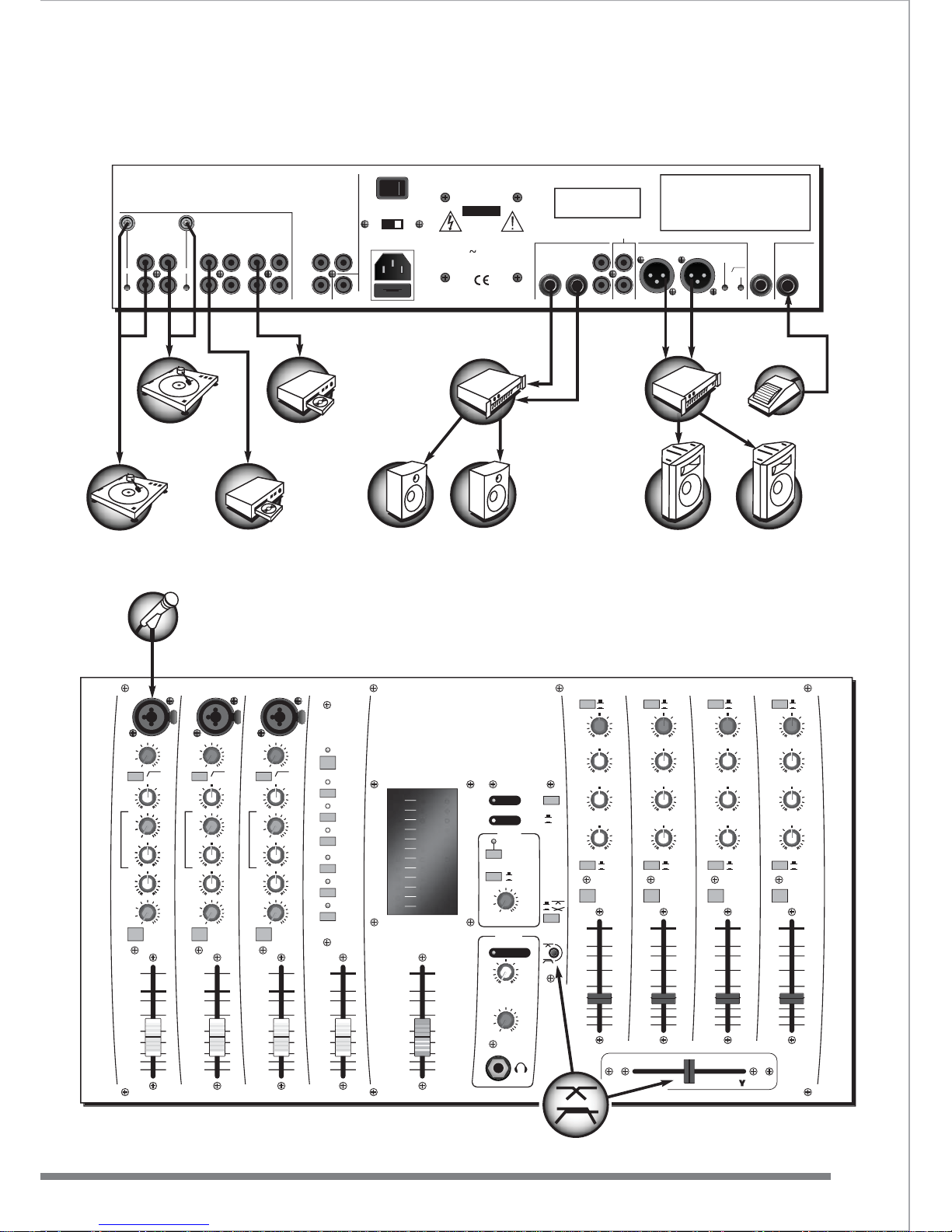
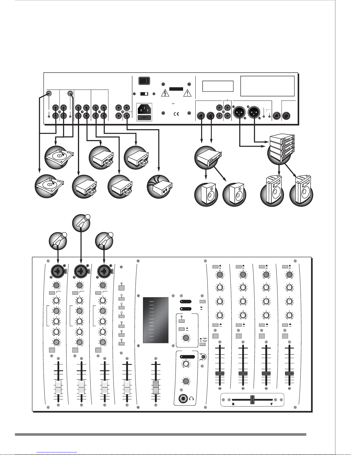
Suggested set-up
Page 14
GET YOU UP AND RUNNING
SET-UPS
12
www.studiomaster.com
www.studiomaster.com
TAPER 2
CUE ACTIVE
POWER
MONO
0dB
-10
-15
-20
-30
-40
8
-5
11109876
0dB
-10
-15
-20
-30
-40
8
-5
0dB
-10
-15
-20
-30
-40
8
-5
0dB
-10
-15
-20
-30
-40
8
-5
0dB
-10
-15
-20
-30
-40
8
-5
54
OUTPUT
+10
+8
+6
+4
+2
0dB
-3
-6
-9
-12
-15
-20
OUTPUT
CUERL
VCA
XF1
0dB
-10
-15
-20
-30
-40
8
8
-5
+5
-5
-10
-15
-20
-30
0dB
8
+5
-5
-10
-15
-20
-30
0dB
8
+5
-5
-10
-15
-20
-30
0dB
-
+
LO
60Hz
-
+
AUX /
DSP
CUE
0 10
LO
60Hz
-
+
AUX /
DSP
CUE
0 10
LO
60Hz
-
+
AUX /
DSP
CUE
0 10
MIC
GAIN
80Hz
18dB/OCT
DSP
ON
VOCAL
1
SMALL REV
LARGE REV
ADT
CHORUS
ECHO
250Hz 6KHz
MID
-
+
INST VOCAL
1
HHI
I
1122KKHHz
z
-
+
MIC
GAIN
80Hz
18dB/OCT
10 55dB10 55dB
250Hz 6KHz
MID
-
+
INST VOCAL
HHI
I
1122KKHHz
z
-
+
MIC
GAIN
80Hz
18dB/OCT
10 55dB
250Hz 6KHz
MID
-
+
INST VOCAL
HHI
I
1122KKHHz
z
2 3DSP
BOOTH
PHONES
OUTPUT
TO BOOTH
MIC CUT
CUE
0dB +10dB
GAIN
HI
12KHz
MID
1.5KHz
LO
45Hz
0 10
CUE OUTPUT
0 10
GAIN
HI
12KHz
MID
1.5KHz
LO
45Hz
-
10 +10
-
10 +10
-
10 +10
-
10 +10
-
10 +10
-
10 +10
GAIN
HI
12KHz
MID
1KHz
LO
45Hz
GAIN
HI
12KHz
MID
1KHz
LO
45Hz
OUTPUT
Y
CUE
OUTPUT
X
CUE
OUTPUT
Y
CUE
OUTPUT
X
OUTPUT
PHONES
STEREO
MPX
STEREO
MPX
LINE A
LINE B
LINE A
LINE B
LEVEL
LEVEL
-36 +10
-36 +10
-36 +10
-36 +10
-36 +10
-36 +10
0dB +10dB0dB +10dB0dB +10dB
TAPER 1
VIDEO
A
B
OUTPUT
BALANCED
FOOTSWITCH
OUTPUT
BOOTH
LEFTRIGHT
RIGHT
PHONO
GND GND
LEFT
MONO
20Hz
18dB
PHONO
STUDIOMASTER MODEL - FUSION
SERIAL
NUMBER
HERE
WARNING: THIS UNIT MUST BE EARTHED.
CAUTION: TO REDUCE THE RISK OF ELECTRIC SHOCK DO NOT
REMOVE COVER. NO USER SERVICEABLE PARTS INSIDE.
REFER SERVICING TO QUALIFIED SERVICE PERSONNEL.
TO REDUCE THE RISK OF FIRE OR ELECTRIC SHOCK DO NOT EXPOSE
THIS EQUIPMENT TO RAIN OR MOISTURE.
AVIS:RISQUE DE CHOC ELECTRIQUE. NE PAS OUVRIR.
CAUTION: TO REDUCE THE RISK OF FIRE REPLACE FUSE ONLYWITH
SAME TYPE AND RATING.
ATTENTION:UTILISER UN FUSIBLE DE RECHANGE DE MEME TYPE.
10-11 8-9 6-7 4-5
AUX
OUTPUT
INPUT
OUTPUT/
RECORD
LINE
LEFT
LINE
LEFT
LINE B
LEFT
LINE A
LEFT
LINE B
LEFT
LINE A
LEFT
VIDEO IN
A
A
VIDEO IN
B
B
VIDEO OUT
MONO OUTPUT
RIGHTRIGHT RIGHTRIGHT RIGHTRIGHT
RIGHT RIGHT
LEFT LEFT
RISK OF
ELECTRIC SHOCK
DO NOT OPEN
CAUTION
FUSE T160mAL 250V for 230V
FUSE T200mAL 250V for 115V
115/230V
50/60Hz 22 Watts Max
O
I
(-6dB)
M
I
N
I
-
D
I
S
C
P
L
A
Y
E
R
M
I
N
I
-
D
I
S
C
P
L
A
Y
E
R
G
U
I
T
A
R
S
P
E
A
K
E
R
S
S
P
E
A
K
E
R
S
A
M
P
L
I
F
I
E
R
F
O
O
T
S
W
I
T
C
H
M
I
C
R
O
P
H
O
N
E
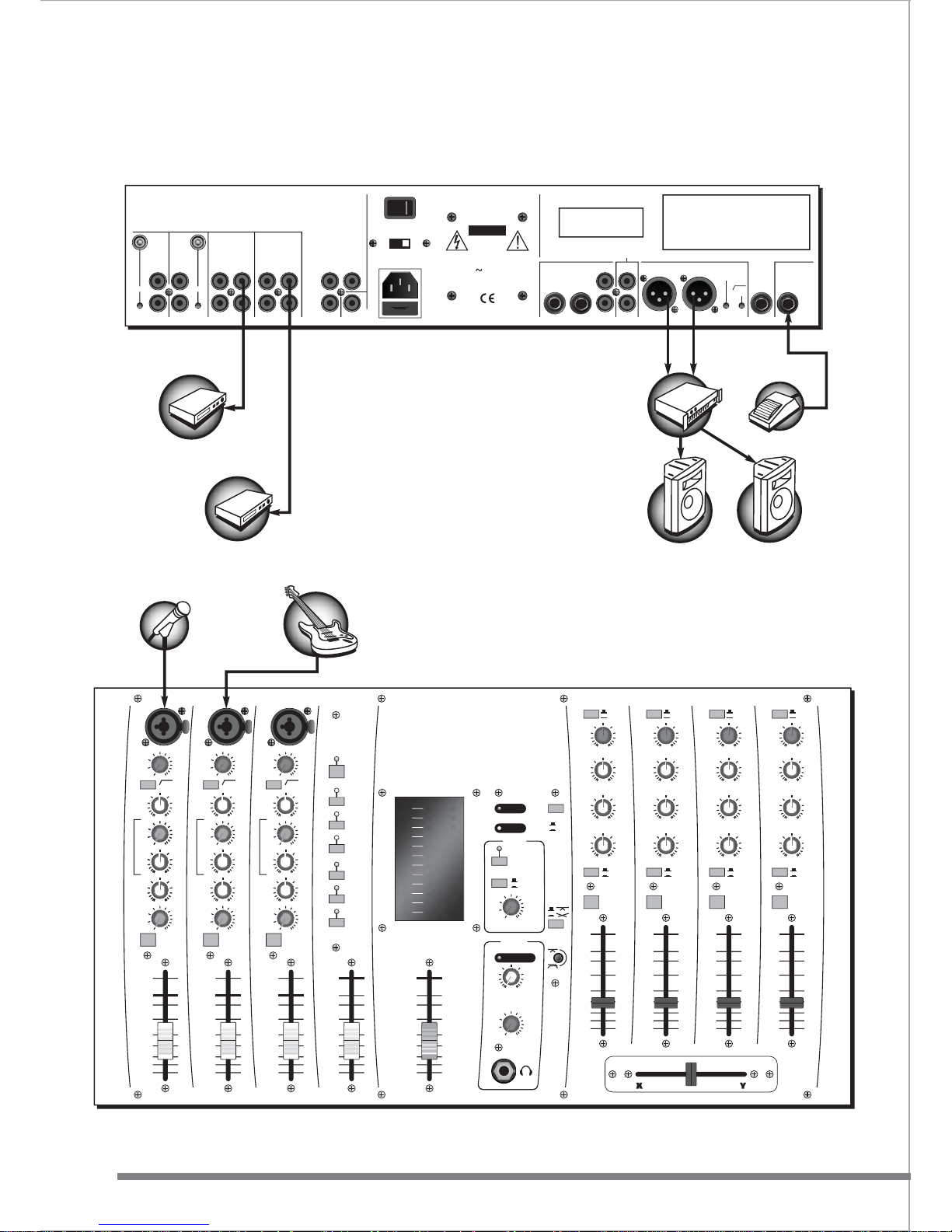
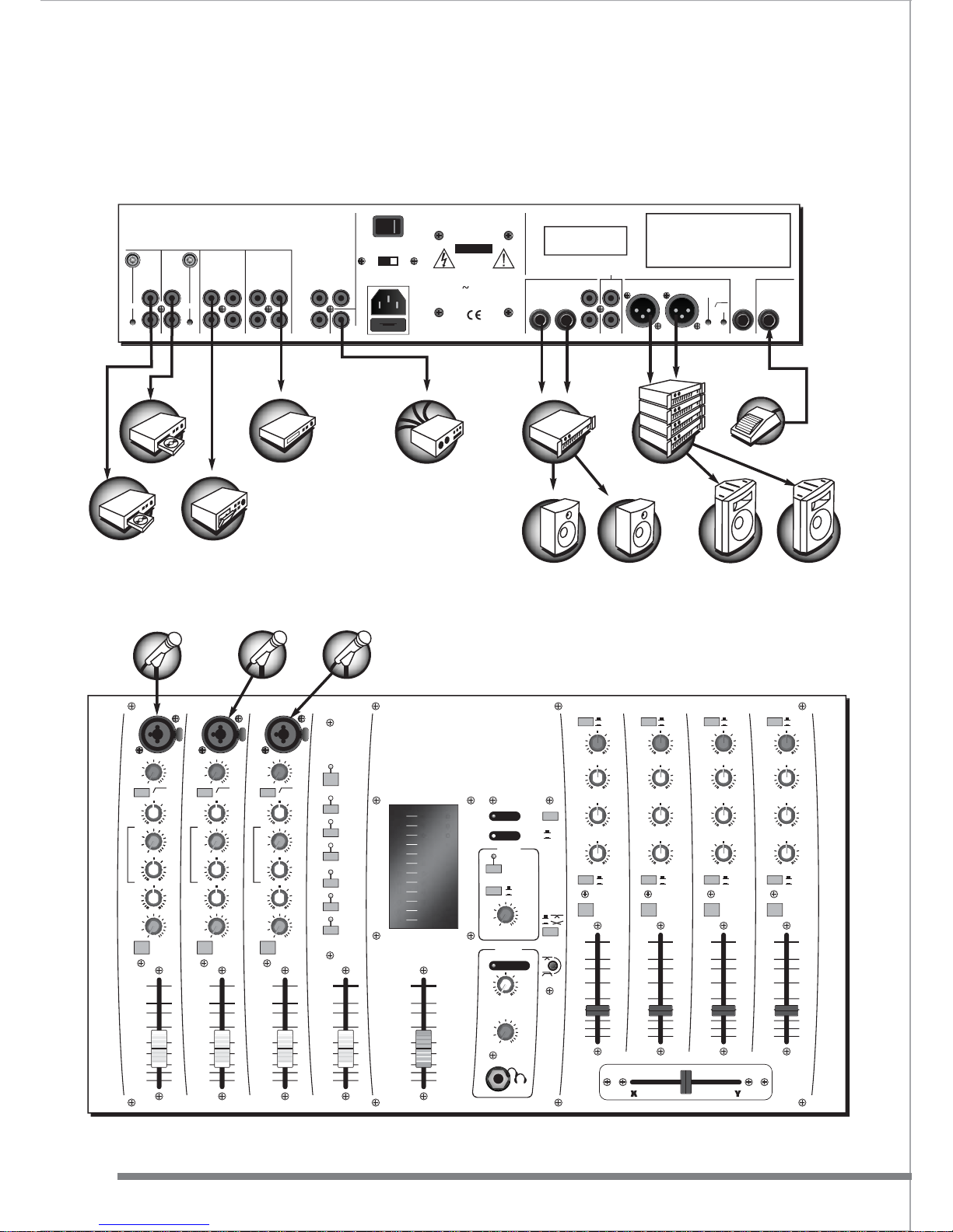
Solo performer
Suggested set-up
A
B
Page 15
TAPER 2
CUE ACTIVE
POWER
MONO
0dB
-10
-15
-20
-30
-40
8
-5
11109876
0dB
-10
-15
-20
-30
-40
8
-5
0dB
-10
-15
-20
-30
-40
8
-5
0dB
-10
-15
-20
-30
-40
8
-5
0dB
-10
-15
-20
-30
-40
8
-5
54
OUTPUT
+10
+8
+6
+4
+2
0dB
-3
-6
-9
-12
-15
-20
OUTPUT
CUERL
VCA XF1
0dB
-10
-15
-20
-30
-40
8
8
-5
+5
-5
-10
-15
-20
-30
0dB
8
+5
-5
-10
-15
-20
-30
0dB
8
+5
-5
-10
-15
-20
-30
0dB
-
+
LO
60Hz
-
+
AUX /
DSP
CUE
0 10
LO
60Hz
-
+
AUX /
DSP
CUE
0 10
LO
60Hz
-
+
AUX /
DSP
CUE
0 10
MIC
GAIN
80Hz
18dB/OCT
DSP
ON
VOCAL 1
SMALL REV
LARGE REV
ADT
CHORUS
ECHO
250Hz 6KHz
MID
-
+
INST VOCAL
1
HHI
I
1122KKHHz
z
-
+
MIC
GAIN
80Hz
18dB/OCT
10 55dB10 55dB
250Hz 6KHz
MID
-
+
INST VOCAL
HHI
I
1122KKHHz
z
-
+
MIC
GAIN
80Hz
18dB/OCT
10 55dB
250Hz 6KHz
MID
-
+
INST VOCAL
HHI
I
1122KKHHz
z
2 3DSP
BOOTH
PHONES
OUTPUT
TO BOOTH
MIC CUT
CUE
0dB +10dB
GAIN
HI
12KHz
MID
1.5KHz
LO
45Hz
0 10
CUE OUTPUT
0 10
GAIN
HI
12KHz
MID
1.5KHz
LO
45Hz
-
10 +10
-
10 +10
-
10 +10
-
10 +10
-
10 +10
-
10 +10
GAIN
HI
12KHz
MID
1KHz
LO
45Hz
GAIN
HI
12KHz
MID
1KHz
LO
45Hz
OUTPUT
Y
CUE
OUTPUT
X
CUE
OUTPUT
Y
CUE
OUTPUT
X
OUTPUT
PHONES
STEREO
MPX
STEREO
MPX
LINE A
LINE B
LINE A
LINE B
LEVEL
LEVEL
-36 +10
-36 +10
-36 +10
-36 +10
-36 +10
-36 +10
0dB +10dB0dB +10dB0dB +10dB
TAPER 1
VIDEO
A
B
GET YOU UP AND RUNNING
SET-UPS
EXPECT THE BEST
EXPECT THE BEST
13
OUTPUT
BALANCED
FOOTSWITCH
OUTPUT
BOOTH
LEFTRIGHT
RIGHT
PHONO
GND GND
LEFT
MONO
20Hz
18dB
PHONO
STUDIOMASTER MODEL - FUSION
SERIAL
NUMBER
HERE
WARNING: THIS UNIT MUST BE EARTHED.
CAUTION: TO REDUCE THE RISK OF ELECTRIC SHOCK DO NOT
REMOVE COVER. NO USER SERVICEABLE PARTS INSIDE.
REFER SERVICING TO QUALIFIED SERVICE PERSONNEL.
TO REDUCE THE RISK OF FIRE OR ELECTRIC SHOCK DO NOT EXPOSE
THIS EQUIPMENT TO RAIN OR MOISTURE.
AVIS:RISQUE DE CHOC ELECTRIQUE. NE PAS OUVRIR.
CAUTION: TO REDUCE THE RISK OF FIRE REPLACE FUSE ONLYWITH
SAME TYPE AND RATING.
ATTENTION:UTILISER UN FUSIBLE DE RECHANGE DE MEME TYPE.
10-11 8-9 6-7 4-5
AUX
OUTPUT
INPUT
OUTPUT/
RECORD
LINE
LEFT
LINE
LEFT
LINE B
LEFT
LINE A
LEFT
LINE B
LEFT
LINE A
LEFT
VIDEO IN
A
A
VIDEO IN
B
B
VIDEO OUT
MONO OUTPUT
RIGHTRIGHT RIGHTRIGHT RIGHTRIGHT
RIGHT RIGHT
LEFT LEFT
RISK OF
ELECTRIC SHOCK
DO NOT OPEN
CAUTION
FUSE T160mAL 250V for 230V
FUSE T200mAL 250V for 115V
115/230V
50/60Hz 22 Watts Max
O
I
(-6dB)
K
E
Y
B
O
A
R
D
M
I
C
R
O
P
H
O
N
E
M
I
C
R
O
P
H
O
N
E
G
U
I
T
A
R
S
O
U
N
D
M
O
D
U
L
E
S
P
E
A
K
E
R
S
S
P
E
A
K
E
R
S
A
M
P
L
I
F
I
E
R
F
O
O
T
S
W
I
T
C
H
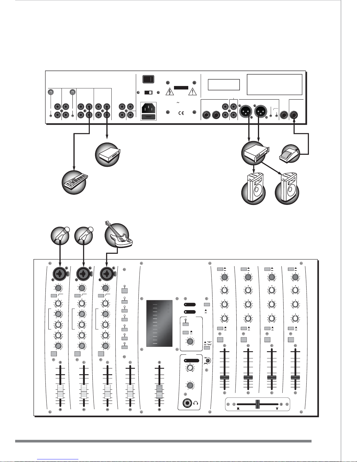
Duo
Suggested set-up
Page 16
TAPER 2
CUE ACTIVE
POWER
MONO
0dB
-10
-15
-20
-30
-40
8
-5
11109876
0dB
-10
-15
-20
-30
-40
8
-5
0dB
-10
-15
-20
-30
-40
8
-5
0dB
-10
-15
-20
-30
-40
8
-5
0dB
-10
-15
-20
-30
-40
8
-5
54
OUTPUT
+10
+8
+6
+4
+2
0dB
-3
-6
-9
-12
-15
-20
OUTPUT
CUERL
VCA XF1
0dB
-10
-15
-20
-30
-40
8
8
-5
+5
-5
-10
-15
-20
-30
0dB
8
+5
-5
-10
-15
-20
-30
0dB
8
+5
-5
-10
-15
-20
-30
0dB
-
+
LO
60Hz
-
+
AUX /
DSP
CUE
0 10
LO
60Hz
-
+
AUX /
DSP
CUE
0 10
LO
60Hz
-
+
AUX /
DSP
CUE
0 10
MIC
GAIN
80Hz
18dB/OCT
DSP
ON
VOCAL 1
SMALL REV
LARGE REV
ADT
CHORUS
ECHO
250Hz 6KHz
MID
-
+
INST VOCAL
1
HHI
I
1122KKHHz
z
-
+
MIC
GAIN
80Hz
18dB/OCT
10 55dB10 55dB
250Hz 6KHz
MID
-
+
INST VOCAL
HHI
I
1122KKHHz
z
-
+
MIC
GAIN
80Hz
18dB/OCT
10 55dB
250Hz 6KHz
MID
-
+
INST VOCAL
HHI
I
1122KKHHz
z
2 3DSP
BOOTH
PHONES
OUTPUT
TO BOOTH
MIC CUT
CUE
0dB +10dB
GAIN
HI
12KHz
MID
1.5KHz
LO
45Hz
0 10
CUE OUTPUT
0 10
GAIN
HI
12KHz
MID
1.5KHz
LO
45Hz
-
10 +10
-
10 +10
-
10 +10
-
10 +10
-
10 +10
-
10 +10
GAIN
HI
12KHz
MID
1KHz
LO
45Hz
GAIN
HI
12KHz
MID
1KHz
LO
45Hz
OUTPUT
Y
CUE
OUTPUT
X
CUE
OUTPUT
Y
CUE
OUTPUT
X
OUTPUT
PHONES
STEREO
MPX
STEREO
MPX
LINE A
LINE B
LINE A
LINE B
LEVEL
LEVEL
-36 +10
-36 +10
-36 +10
-36 +10
-36 +10
-36 +10
0dB +10dB0dB +10dB0dB +10dB
TAPER 1
VIDEO
A
B
GET YOU UP AND RUNNING
SET-UPS
14
www.studiomaster.com
www.studiomaster.com
OUTPUT
BALANCED
FOOTSWITCH
OUTPUT
BOOTH
LEFTRIGHT
RIGHT
PHONO
GND GND
LEFT
MONO
20Hz
18dB
PHONO
STUDIOMASTER MODEL - FUSION
SERIAL
NUMBER
HERE
WARNING: THIS UNIT MUST BE EARTHED.
CAUTION: TO REDUCE THE RISK OF ELECTRIC SHOCK DO NOT
REMOVE COVER. NO USER SERVICEABLE PARTS INSIDE.
REFER SERVICING TO QUALIFIED SERVICE PERSONNEL.
TO REDUCE THE RISK OF FIRE OR ELECTRIC SHOCK DO NOT EXPOSE
THIS EQUIPMENT TO RAIN OR MOISTURE.
AVIS:RISQUE DE CHOC ELECTRIQUE. NE PAS OUVRIR.
CAUTION: TO REDUCE THE RISK OF FIRE REPLACE FUSE ONLYWITH
SAME TYPE AND RATING.
ATTENTION:UTILISER UN FUSIBLE DE RECHANGE DE MEME TYPE.
10-11 8-9 6-7 4-5
AUX
OUTPUT
INPUT
OUTPUT/
RECORD
LINE
LEFT
LINE
LEFT
LINE B
LEFT
LINE A
LEFT
LINE B
LEFT
LINE A
LEFT
VIDEO IN
A
A
VIDEO IN
B
B
VIDEO OUT
MONO OUTPUT
RIGHTRIGHT RIGHTRIGHT RIGHTRIGHT
RIGHT RIGHT
LEFT LEFT
RISK OF
ELECTRIC SHOCK
DO NOT OPEN
CAUTION
FUSE T160mAL 250V for 230V
FUSE T200mAL 250V for 115V
115/230V
50/60Hz 22 Watts Max
O
I
(-6dB)
S
P
E
A
K
E
R
S
S
P
E
A
K
E
R
S
A
M
P
L
I
F
I
E
R
M
I
C
R
O
P
H
O
N
E
C
O
M
P
E
R
E
'
S
M
I
C
R
O
P
H
O
N
E
M
I
C
R
O
P
H
O
N
E
M
I
C
R
O
P
H
O
N
E
F
O
O
T
S
W
I
T
C
H
V
I
D
E
O
M
O
N
I
T
O
R
K
A
R
A
O
K
E
M
A
C
H
I
N
E
C
D
P
L
A
Y
E
R
C
D
P
L
A
Y
E
R
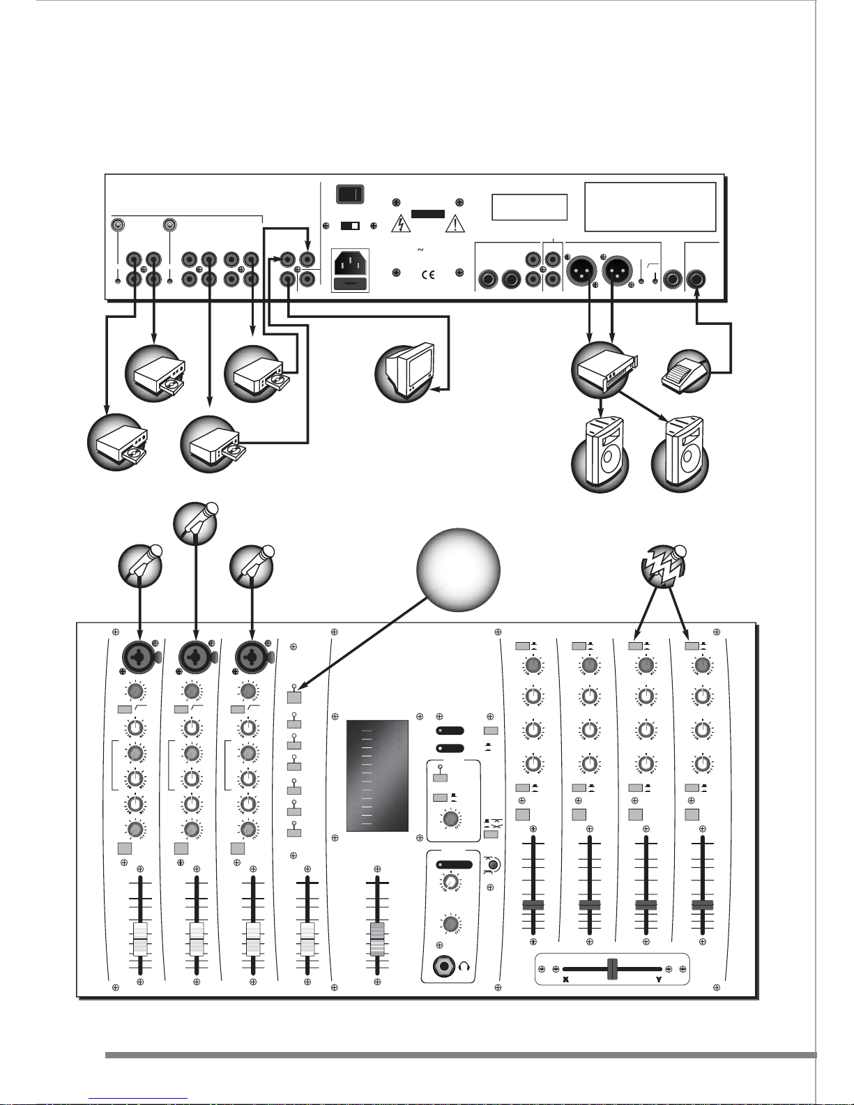
Karaoke
Suggested set-up
K
A
R
A
O
K
E
M
A
C
H
I
N
E
SET
ONBOARD
DSP TO GET
GREAT VOCAL
EFFECTS
MPX FOR
VOCAL CUT
Page 17
TAPER 2
CUE ACTIVE
POWER
MONO
0dB
-10
-15
-20
-30
-40
8
-5
11109876
0dB
-10
-15
-20
-30
-40
8
-5
0dB
-10
-15
-20
-30
-40
8
-5
0dB
-10
-15
-20
-30
-40
8
-5
0dB
-10
-15
-20
-30
-40
8
-5
54
OUTPUT
+10
+8
+6
+4
+2
0dB
-3
-6
-9
-12
-15
-20
OUTPUT
CUERL
VCA XF1
0dB
-10
-15
-20
-30
-40
8
8
-5
+5
-5
-10
-15
-20
-30
0dB
8
+5
-5
-10
-15
-20
-30
0dB
8
+5
-5
-10
-15
-20
-30
0dB
-
+
LO
60Hz
-
+
AUX /
DSP
CUE
0 10
LO
60Hz
-
+
AUX /
DSP
CUE
0 10
LO
60Hz
-
+
AUX /
DSP
CUE
0 10
MIC
GAIN
80Hz
18dB/OCT
DSP
ON
VOCAL 1
SMALL REV
LARGE REV
ADT
CHORUS
ECHO
250Hz 6KHz
MID
-
+
INST VOCAL
1
HHI
I
1122KKHHz
z
-
+
MIC
GAIN
80Hz
18dB/OCT
10 55dB10 55dB
250Hz 6KHz
MID
-
+
INST VOCAL
HHI
I
1122KKHHz
z
-
+
MIC
GAIN
80Hz
18dB/OCT
10 55dB
250Hz 6KHz
MID
-
+
INST VOCAL
HHI
I
1122KKHHz
z
2 3DSP
BOOTH
PHONES
OUTPUT
TO BOOTH
MIC CUT
CUE
0dB +10dB
GAIN
HI
12KHz
MID
1.5KHz
LO
45Hz
0 10
CUE OUTPUT
0 10
GAIN
HI
12KHz
MID
1.5KHz
LO
45Hz
-
10 +10
-
10 +10
-
10 +10
-
10 +10
-
10 +10
-
10 +10
GAIN
HI
12KHz
MID
1KHz
LO
45Hz
GAIN
HI
12KHz
MID
1KHz
LO
45Hz
OUTPUT
Y
CUE
OUTPUT
X
CUE
OUTPUT
Y
CUE
OUTPUT
X
OUTPUT
PHONES
STEREO
MPX
STEREO
MPX
LINE A
LINE B
LINE A
LINE B
LEVEL
LEVEL
-36 +10
-36 +10
-36 +10
-36 +10
-36 +10
-36 +10
0dB +10dB0dB +10dB0dB +10dB
TAPER 1
VIDEO
A
B
GET YOU UP AND RUNNING
SET-UPS
15
EXPECT THE BEST
EXPECT THE BEST
C
D
P
L
A
Y
E
R
OUTPUT
BALANCED
FOOTSWITCH
OUTPUT
BOOTH
LEFTRIGHT
RIGHT
PHONO
GND GND
LEFT
MONO
20Hz
18dB
PHONO
STUDIOMASTER MODEL - FUSION
SERIAL
NUMBER
HERE
WARNING: THIS UNIT MUST BE EARTHED.
CAUTION: TO REDUCE THE RISK OF ELECTRIC SHOCK DO NOT
REMOVE COVER. NO USER SERVICEABLE PARTS INSIDE.
REFER SERVICING TO QUALIFIED SERVICE PERSONNEL.
TO REDUCE THE RISK OF FIRE OR ELECTRIC SHOCK DO NOT EXPOSE
THIS EQUIPMENT TO RAIN OR MOISTURE.
AVIS:RISQUE DE CHOC ELECTRIQUE. NE PAS OUVRIR.
CAUTION: TO REDUCE THE RISK OF FIRE REPLACE FUSE ONLYWITH
SAME TYPE AND RATING.
ATTENTION:UTILISER UN FUSIBLE DE RECHANGE DE MEME TYPE.
10-11 8-9 6-7 4-5
AUX
OUTPUT
INPUT
OUTPUT/
RECORD
LINE
LEFT
LINE
LEFT
LINE B
LEFT
LINE A
LEFT
LINE B
LEFT
LINE A
LEFT
VIDEO IN
A
A
VIDEO IN
B
B
VIDEO OUT
MONO OUTPUT
RIGHTRIGHT RIGHTRIGHT RIGHTRIGHT
RIGHT RIGHT
LEFT LEFT
RISK OF
ELECTRIC SHOCK
DO NOT OPEN
CAUTION
FUSE T160mAL 250V for 230V
FUSE T200mAL 250V for 115V
115/230V
50/60Hz 22 Watts Max
O
I
(-6dB)
M
A
I
N
S
Y
S
T
E
M
D
J
M
I
C
G
U
E
S
T
D
J
M
I
C
R
A
D
I
O
M
I
C
T
U
R
N
T
A
B
L
E
T
U
R
N
T
A
B
L
E
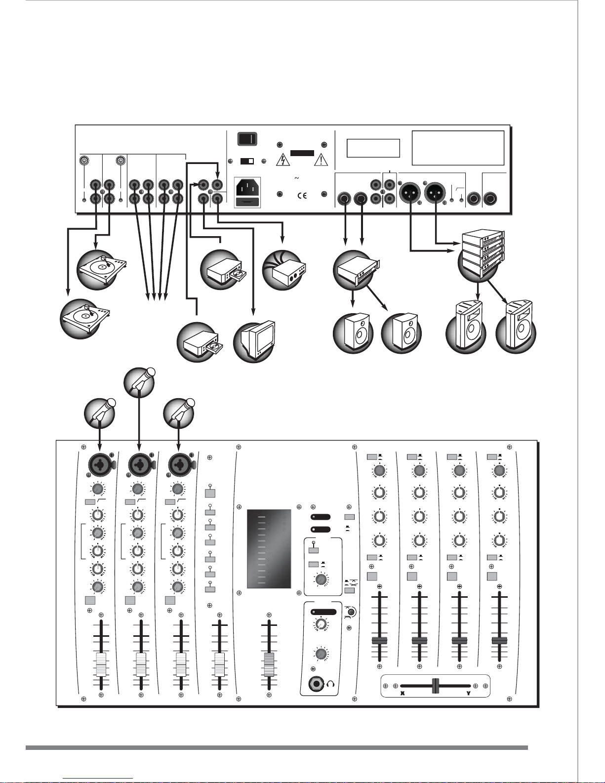
Club Mixer
Suggested set-up
C
D
P
L
A
Y
E
R
C
D
P
L
A
Y
E
R
L
I
G
H
T
I
N
G
S
E
Q
U
E
N
C
E
R
C
D
P
L
A
Y
E
R
B
O
O
T
H
S
P
E
A
K
E
R
S
B
O
O
T
H
S
P
E
A
K
E
R
S
B
O
O
T
H
A
M
P
L
I
F
I
E
R
13
24
S
P
E
A
K
E
R
S
S
P
E
A
K
E
R
S
Page 18
TAPER 2
CUE ACTIVE
POWER
MONO
0dB
-10
-15
-20
-30
-40
8
-5
11109876
0dB
-10
-15
-20
-30
-40
8
-5
0dB
-10
-15
-20
-30
-40
8
-5
0dB
-10
-15
-20
-30
-40
8
-5
0dB
-10
-15
-20
-30
-40
8
-5
54
OUTPUT
+10
+8
+6
+4
+2
0dB
-3
-6
-9
-12
-15
-20
OUTPUT
CUERL
VCA XF1
0dB
-10
-15
-20
-30
-40
8
8
-5
+5
-5
-10
-15
-20
-30
0dB
8
+5
-5
-10
-15
-20
-30
0dB
8
+5
-5
-10
-15
-20
-30
0dB
-
+
LO
60Hz
-
+
AUX /
DSP
CUE
0 10
LO
60Hz
-
+
AUX /
DSP
CUE
0 10
LO
60Hz
-
+
AUX /
DSP
CUE
0 10
MIC
GAIN
80Hz
18dB/OCT
DSP
ON
VOCAL 1
SMALL REV
LARGE REV
ADT
CHORUS
ECHO
250Hz 6KHz
MID
-
+
INST VOCAL
1
HHI
I
1122KKHHz
z
-
+
MIC
GAIN
80Hz
18dB/OCT
10 55dB10 55dB
250Hz 6KHz
MID
-
+
INST VOCAL
HHI
I
1122KKHHz
z
-
+
MIC
GAIN
80Hz
18dB/OCT
10 55dB
250Hz 6KHz
MID
-
+
INST VOCAL
HHI
I
1122KKHHz
z
2 3DSP
BOOTH
PHONES
OUTPUT
TO BOOTH
MIC CUT
CUE
0dB +10dB
GAIN
HI
12KHz
MID
1.5KHz
LO
45Hz
0 10
CUE OUTPUT
0 10
GAIN
HI
12KHz
MID
1.5KHz
LO
45Hz
-
10 +10
-
10 +10
-
10 +10
-
10 +10
-
10 +10
-
10 +10
GAIN
HI
12KHz
MID
1KHz
LO
45Hz
GAIN
HI
12KHz
MID
1KHz
LO
45Hz
OUTPUT
Y
CUE
OUTPUT
X
CUE
OUTPUT
Y
CUE
OUTPUT
X
OUTPUT
PHONES
STEREO
MPX
STEREO
MPX
LINE A
LINE B
LINE A
LINE B
LEVEL
LEVEL
-36 +10
-36 +10
-36 +10
-36 +10
-36 +10
-36 +10
0dB +10dB0dB +10dB0dB +10dB
TAPER 1
VIDEO
A
B
GET YOU UP AND RUNNING
SET-UPS
16
www.studiomaster.com
www.studiomaster.com
M
I
N
I
-
D
I
S
C
P
L
A
Y
E
R
OUTPUT
BALANCED
FOOTSWITCH
OUTPUT
BOOTH
LEFTRIGHT
RIGHT
PHONO
GND GND
LEFT
MONO
20Hz
18dB
PHONO
STUDIOMASTER MODEL - FUSION
SERIAL
NUMBER
HERE
WARNING: THIS UNIT MUST BE EARTHED.
CAUTION:TO REDUCE THE RISK OF ELECTRIC SHOCK DO NOT
REMOVE COVER. NO USER SERVICEABLE PARTS INSIDE.
REFER SERVICING TO QUALIFIED SERVICE PERSONNEL.
TO REDUCE THE RISK OF FIRE OR ELECTRIC SHOCK DO NOT EXPOSE
THIS EQUIPMENT TO RAIN OR MOISTURE.
AVIS:RISQUE DE CHOC ELECTRIQUE. NE PAS OUVRIR.
CAUTION:TO REDUCE THE RISK OF FIRE REPLACE FUSE ONLY WITH
SAME TYPE AND RATING.
ATTENTION:UTILISER UN FUSIBLE DE RECHANGE DE MEME TYPE.
10-11 8-9 6-7 4-5
AUX
OUTPUT
INPUT
OUTPUT/
RECORD
LINE
LEFT
LINE
LEFT
LINE B
LEFT
LINE A
LEFT
LINE B
LEFT
LINE A
LEFT
VIDEO IN
A
A
VIDEO IN
B
B
VIDEO OUT
MONO OUTPUT
RIGHTRIGHT RIGHTRIGHT RIGHTRIGHT
RIGHT RIGHT
LEFT LEFT
RISK OF
ELECTRIC SHOCK
DO NOT OPEN
CAUTION
FUSE T160mAL 250V for 230V
FUSE T200mAL 250V for 115V
115/230V
50/60Hz 22 Watts Max
O
I
(-6dB)
D
J
/
A
N
N
O
U
N
C
E
R
C
D
P
L
A
Y
E
R
C
D
P
L
A
Y
E
R
Nightclub / Entertainer
Suggested set-up
C
A
S
S
E
T
T
E
P
L
A
Y
E
R
L
I
G
H
T
I
N
G
S
E
Q
U
E
N
C
E
R
M
A
I
N
S
Y
S
T
E
M
B
O
O
T
H
S
P
E
A
K
E
R
S
B
O
O
T
H
S
P
E
A
K
E
R
S
B
O
O
T
H
A
M
P
L
I
F
I
E
R
S
P
E
A
K
E
R
S
S
P
E
A
K
E
R
S
OR ADDITIONAL
CD, MINIDISC
PLAYER
FOR BACKING
TRACKS
FOR STAGE MONITORING
O
R
S
I
N
G
E
R
S
E
N
T
E
R
T
A
I
N
E
R
S
O
R
S
I
N
G
E
R
S
E
N
T
E
R
T
A
I
N
E
R
S
F
O
O
T
S
W
I
T
C
H
Page 19
TAPER 2
CUE ACTIVE
POWER
MONO
0dB
-10
-15
-20
-30
-40
8
-5
11109876
0dB
-10
-15
-20
-30
-40
8
-5
0dB
-10
-15
-20
-30
-40
8
-5
0dB
-10
-15
-20
-30
-40
8
-5
0dB
-10
-15
-20
-30
-40
8
-5
54
OUTPUT
+10
+8
+6
+4
+2
0dB
-3
-6
-9
-12
-15
-20
OUTPUT
CUERL
VCA XF1
0dB
-10
-15
-20
-30
-40
8
8
-5
+5
-5
-10
-15
-20
-30
0dB
8
+5
-5
-10
-15
-20
-30
0dB
8
+5
-5
-10
-15
-20
-30
0dB
-
+
LO
60Hz
-
+
AUX /
DSP
CUE
0 10
LO
60Hz
-
+
AUX /
DSP
CUE
0 10
LO
60Hz
-
+
AUX /
DSP
CUE
0 10
MIC
GAIN
80Hz
18dB/OCT
DSP
ON
VOCAL 1
SMALL REV
LARGE REV
ADT
CHORUS
ECHO
250Hz 6KHz
MID
-
+
INST VOCAL
1
HHI
I
1122KKHHz
z
-
+
MIC
GAIN
80Hz
18dB/OCT
10 55dB10 55dB
250Hz 6KHz
MID
-
+
INST VOCAL
HHI
I
1122KKHHz
z
-
+
MIC
GAIN
80Hz
18dB/OCT
10 55dB
250Hz 6KHz
MID
-
+
INST VOCAL
HHI
I
1122KKHHz
z
2 3DSP
BOOTH
PHONES
OUTPUT
TO BOOTH
MIC CUT
CUE
0dB +10dB
GAIN
HI
12KHz
MID
1.5KHz
LO
45Hz
0 10
CUE OUTPUT
0 10
GAIN
HI
12KHz
MID
1.5KHz
LO
45Hz
-
10 +10
-
10 +10
-
10 +10
-
10 +10
-
10 +10
-
10 +10
GAIN
HI
12KHz
MID
1KHz
LO
45Hz
GAIN
HI
12KHz
MID
1KHz
LO
45Hz
OUTPUT
Y
CUE
OUTPUT
X
CUE
OUTPUT
Y
CUE
OUTPUT
X
OUTPUT
PHONES
STEREO
MPX
STEREO
MPX
LINE A
LINE B
LINE A
LINE B
LEVEL
LEVEL
-36 +10
-36 +10
-36 +10
-36 +10
-36 +10
-36 +10
0dB +10dB0dB +10dB0dB +10dB
TAPER 1
VIDEO
A
B
GET YOU UP AND RUNNING
SET-UPS
17
EXPECT THE BEST
EXPECT THE BEST
OUTPUT
BALANCED
FOOTSWITCH
OUTPUT
BOOTH
LEFTRIGHT
RIGHT
PHONO
GND GND
LEFT
MONO
20Hz
18dB
PHONO
STUDIOMASTER MODEL - FUSION
SERIAL
NUMBER
HERE
WARNING: THIS UNIT MUST BE EARTHED.
CAUTION: TO REDUCE THE RISK OF ELECTRIC SHOCK DO NOT
REMOVE COVER. NO USER SERVICEABLE PARTS INSIDE.
REFER SERVICING TO QUALIFIED SERVICE PERSONNEL.
TO REDUCE THE RISK OF FIRE OR ELECTRIC SHOCK DO NOT EXPOSE
THIS EQUIPMENT TO RAIN OR MOISTURE.
AVIS:RISQUE DE CHOC ELECTRIQUE. NE PAS OUVRIR.
CAUTION: TO REDUCE THE RISK OF FIRE REPLACE FUSE ONLYWITH
SAME TYPE AND RATING.
ATTENTION:UTILISER UN FUSIBLE DE RECHANGE DE MEME TYPE.
10-11 8-9 6-7 4-5
AUX
OUTPUT
INPUT
OUTPUT/
RECORD
LINE
LEFT
LINE
LEFT
LINE B
LEFT
LINE A
LEFT
LINE B
LEFT
LINE A
LEFT
VIDEO IN
A
A
VIDEO IN
B
B
VIDEO OUT
MONO OUTPUT
RIGHTRIGHT RIGHTRIGHT RIGHTRIGHT
RIGHT RIGHT
LEFT LEFT
RISK OF
ELECTRIC SHOCK
DO NOT OPEN
CAUTION
FUSE T160mAL 250V for 230V
FUSE T200mAL 250V for 115V
115/230V
50/60Hz 22 Watts Max
O
I
(-6dB)
M
A
I
N
S
Y
S
T
E
M
M
I
C
R
O
P
H
O
N
E
M
I
C
R
O
P
H
O
N
E
M
I
C
R
O
P
H
O
N
E
T
U
R
N
T
A
B
L
E
T
U
R
N
T
A
B
L
E
Install
Suggested set-up
L
I
G
H
T
I
N
G
S
E
Q
U
E
N
C
E
R
B
O
O
T
H
S
P
E
A
K
E
R
S
B
O
O
T
H
S
P
E
A
K
E
R
S
B
O
O
T
H
A
M
P
L
I
F
I
E
R
S
P
E
A
K
E
R
S
S
P
E
A
K
E
R
S
4 MORE STEREO
INPUTS
BALANCED OR
RADIO MICS
OR SUB BASS
FEED
OR
ZONE
FEED
K
A
R
A
O
K
E
M
A
C
H
I
N
E
K
A
R
A
O
K
E
M
A
C
H
I
N
E
V
I
D
E
O
M
O
N
I
T
O
R
Page 20
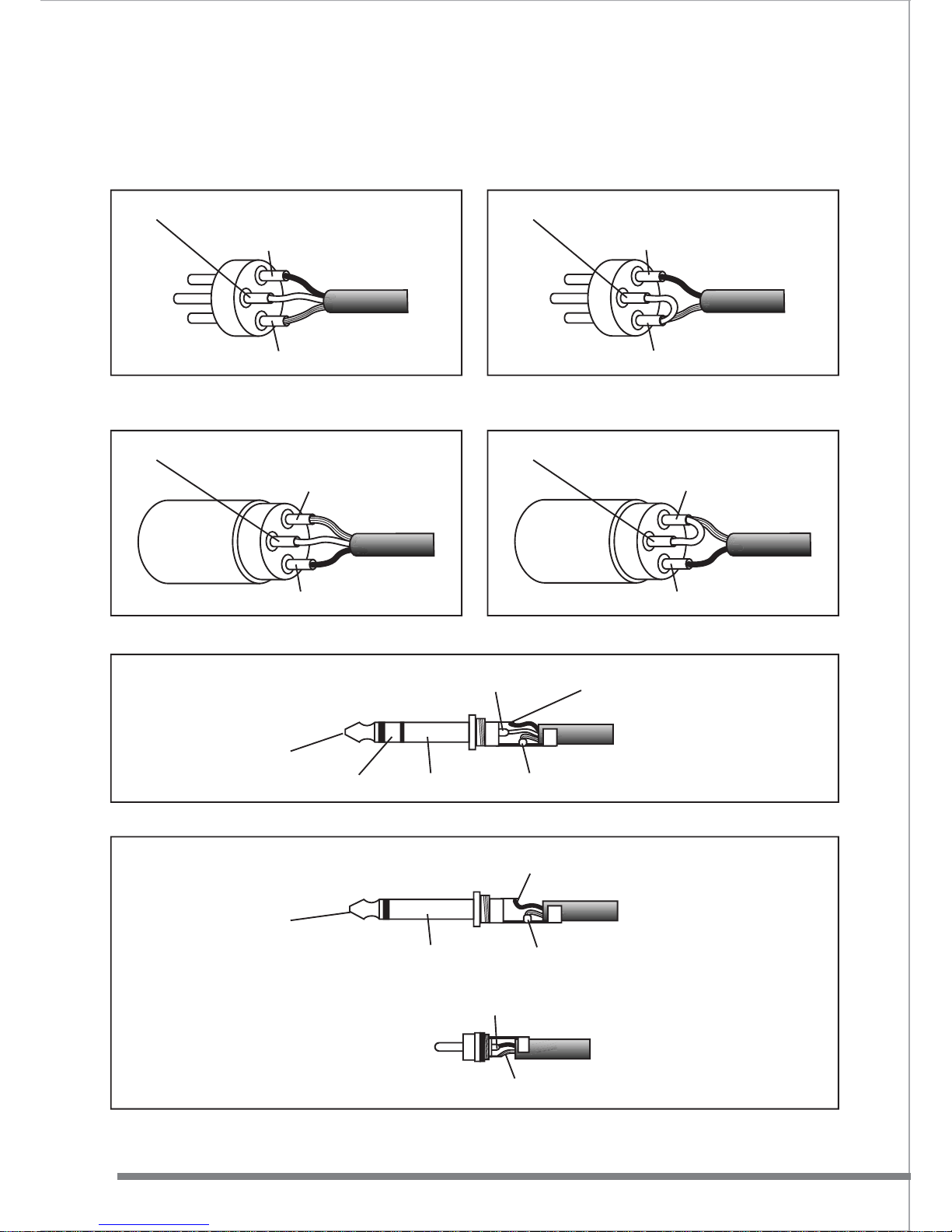
HOW DO I KNOW I HAVE THE RIGHT LEADS
WIRING CONNECTIONS
18
www.studiomaster.com
www.studiomaster.com
To connect a Balanced microphone
to a mic input 3 pin XLR - male
Pin 3 - Negative / Cold / -Ve phase
Ring - Negative / Cold / -Ve phase
Pin 2 - Positive / Hot / +Ve phase
Pin 1 - Screen / Ground / Earth
To connect Balanced equipment to an input or output
To connect an Unbalanced microphone
to a mic input 3 pin XLR - male
Pin 3 - Link to Pin 1
Pin 2 - Positive / Hot / +Ve phase
Pin 1 - Screen / Ground / Earth
To connect a Balanced microphone
to a mic input 3 pin XLR - female
Pin 3 - Negative / Cold / -Ve phase
Pin 1 - Screen / Ground / Earth
Pin 2 - Positive / Hot / +Ve phase
To connect an Unbalanced microphone
to a mic input 3 pin XLR - female
Pin 3 - Link to Pin 1
Pin 1 - Screen / Ground / Earth
Pin 2 - Positive / Hot / +Ve phase
Tip - Positive / Hot / +Ve phase
Sleeve - Screen / Ground / Earth
Tip
Ring Sleeve
Tip - Signal
Tip - Signal
To connect Unbalanced equipment to an input or output
Sleeve - Screen / Ground / Earth
Sleeve - Screen / Ground / Earth
Tip
Sleeve
Page 21
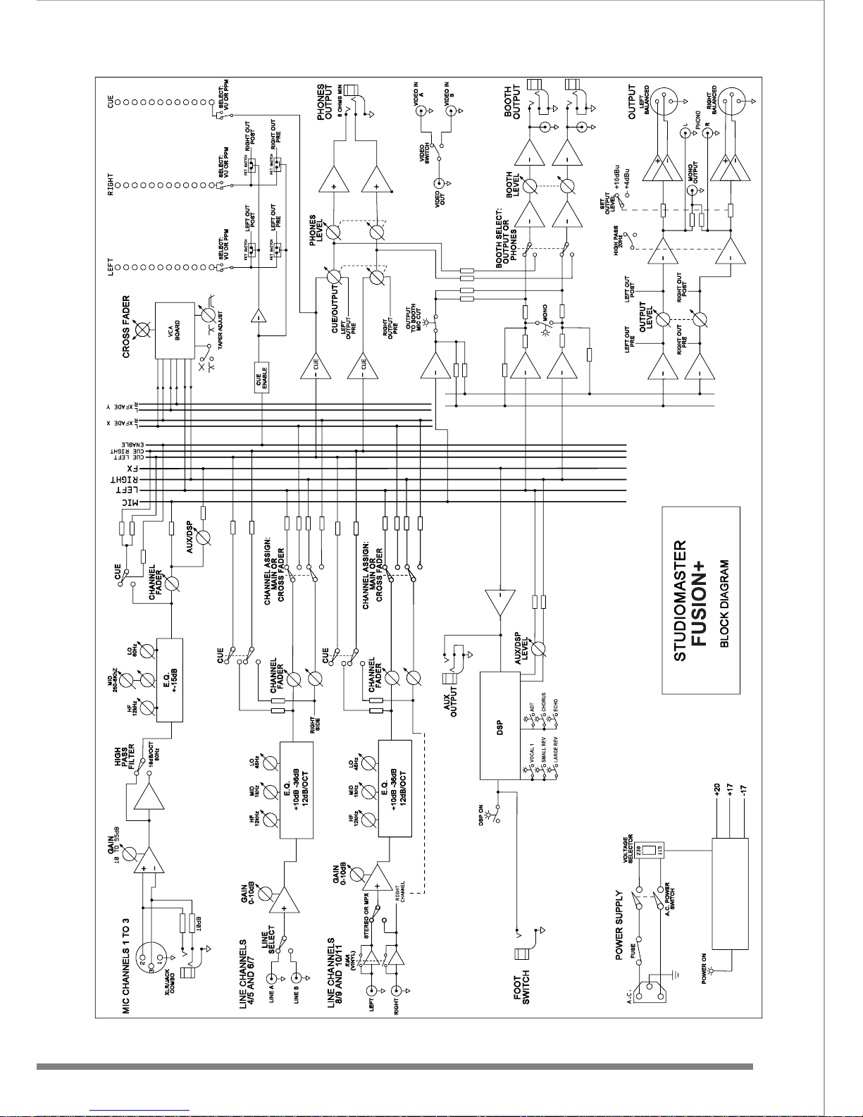
BLOCK DIAGRAM
19
EXPECT THE BEST
EXPECT THE BEST
Page 22

FACTS & FIGURES
TECHNICAL SPECIFICATION
20
www.studiomaster.com
www.studiomaster.com
Input gain Min Max Max to output
Mic 10dB 55dB 60dB
Line 0dB 45dB 50dB
Stereo 4/5-6/7 0dB 10dB 10dB
Stereo 8/9-10/11 0dB 10dB 10dB
E.Q LF Mid HF Cut/boost dB/Octave
Mic/Line 50Hz 250-6kHz 12kHz +/-15dB 6
Stereo 4/5-6/7 45Hz 1.5kHz 12kHz +/-10dB 6
Stereo 8/9-10/11 45Hz 1kHz 12kHz +10/-36dB (max) 12
Mic/Line High pass filter 80Hz 18dB/octave
Noise
Mic EIN -127.5dBu
Signal to noise ratio >85dB (unweighted) with typical control settings
Dynamic range >105dB
Input Impedance Maximum signal level
Mic 5k ohm +10dBu
Line 15k ohm +20dBu
Stereo 4/5-6/7 10k ohm +22dBu
Stereo 8/9-10/11 47k ohm +22dBu
Outputs Impedance Nominal signal level Maximum signal level
Left-Right (XLR) 150 ohms +10dBu (int. adj. +4dBu) +28dBu (bal) +22dBu (unbal)
Left-Right (RCA/phono) 600 ohms -10dBV +8dBV
Mono (RCA/phono) 600 ohms -10dBV +8dBV
Booth (jack) 30 ohms +4dBu +22dBu
Booth (RCA/phono) 600 ohms -10dBV +8dBV
Aux (jack) 30 ohms +4dBu +22dBu
Headphones (jack) 30 ohms Optimal load impedance 150-200 ohms
Output power 400mW/ch into 150 ohms
Output power 100mW/ch into 32 ohms
Frequency response
20Hz - 20kHz +/-0.3dB
10Hz - 50kHz +/-1dB
RIAA (phono) magnetic cartridge equalization accurate to +/-0.3dB
Distortion
THD @ 1kHz 0.0035% Stereo line input to Left-Right output @ nominal level
Video switcher (A or B input selected on front panel)
A/B inputs: standard composite video signal on RCA/phono connectors, 75ohms input impedance
Output: single RCA/phono connector
A.C. power Voltage range Fuse
230V 220V-240V T160mAL
115V 110V-120V T200mAL
50/60Hz, 22Watts max.
Dimensions Width Height Depth
(mm/inches) 482/19" 266/10.5" 114/4.5"
When racked the unit occupies 6 rack spaces.
Weight net gross
6kg/13.2lb 8kg/17.6lb
Page 23

In Accordance with our progressive product development, Studiomaster
reserve the right to change features and specifications without prior notice.
NOTES
NOTES
EXPECT THE BEST
EXPECT THE BEST
Page 24
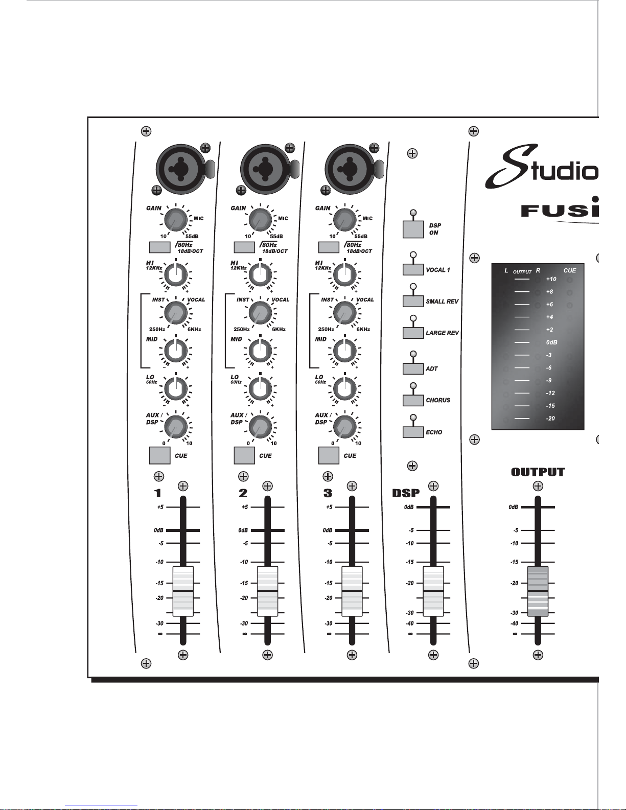
www.studiomaster.com
STUDIOKING LIMITED
Unit 1 Youngs Industrial Estate, Stanbridge Road, Leighton Buzzard, Bedfordshire LU7 4QB UK
Tel : 44 (0)1525 217111 Fax : 44 (0)1525 378466 Email : [email protected]
EXPECT THE BEST
EXPECT THE BEST
FUSION+M ENG V1
 Loading...