

Page 1
Page 2
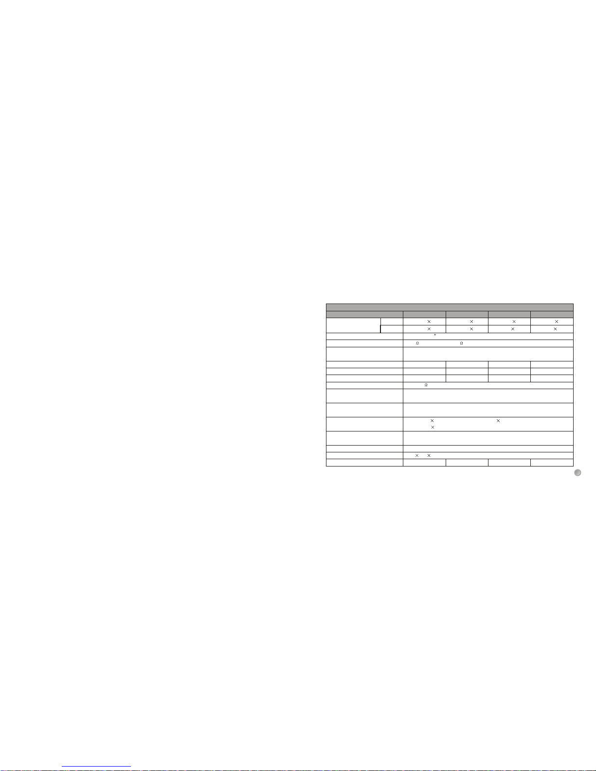
Stereo mode,
(Both channels driven)
1KHz
Input sensitivity
Input impedance
Frequency response
(at 10dB below rated output power)
Voltage gain
Distortion (10W, 1kHz, 4ohms)
S/N ratio (A-Weighted)
Damping factor
ELECTRICAL SPECIFICATIONS
10K Unbalanced 20K Balanced
300 @4
Protections
Controls
Indicators
Connectors
Power supply
Dimensions
Weight
DC protection, short-circuit protection, thermal protection,
overload protection, clip limiter
Front: AC switch, input level control for each channel.
Rear: clip ON/OFF selector
SIGNAL: 2 green LED CLIP: 2 red LED
POWER: 2 blue LED
INPUT: Active balanced XLR, 1/4"(6.3mm)TRS and unbalanced RCA
OUTPUT: "Touch-proof" binding posts and Speakon
Available for 110-120V or 220~240V AC 50/60Hz
5. TECHNICAL SPECIFICATIONS
9
4ohms
8ohms
Balanced 1/4 TRS and XLR: 0.89V(-1dBV); unbalanced RCA: 1.67V (4.5dBV)
5Hz ~ 20kHz, +0/-1dB
30dB
29dB 27.5dB 26dB
<0.05% <0.05% <0.05% <0.05%
>100dB >100dB >100dB >100dB
480 330 43mm
9.5kg 8.5kg 8kg
7.5kg
250W 2 200W 2 150W 2 100W 2
500W
400W 300W 200W
140W 2 120W 2 85W 2 60W 2
Page 3
ON: Denotes the apparatus is turned on
OFF: Denotes the apparatus is turned off.
CAUTION: Describes precautions that should be observed to
prevent danger of the apparatus.
CAUTION
RISK OF ELECTRIC SHOCK
DO NOT OPEN
Protective grounding terminal
WARNING: Describes precautions that should be observed to
prevent the danger of injury or death to the operator.
¡ã¡ã
The symbol is used to indicate that some hazardous live
terminals are involved within this apparatus, even under
the normal operating conditions, which may be sufficient
to constitute the risk of electric shock or death.
The symbol is used in the service documentation to indicate that specific component shall be replaced only by
the component specified in that documentation for safety
reasons.
Alternating current/voltage
Hazardous live terminal
Read these instructions.
Keep these instructions.
Heed all warning.
Follow all instructions.
Water & Moisture
The apparatus should be protected from moisture and rain,
can not used near water, for example: near bathtub, kitchen
sink or a swimming pool, etc.
Heat
The apparatus should be located away from the heat source
such as radiators, stoves or other appliances that produce
heat.
IMPORTANT SAFETY SYMBOLS
IMPORTANT SAFETY INSTRUCTIONS
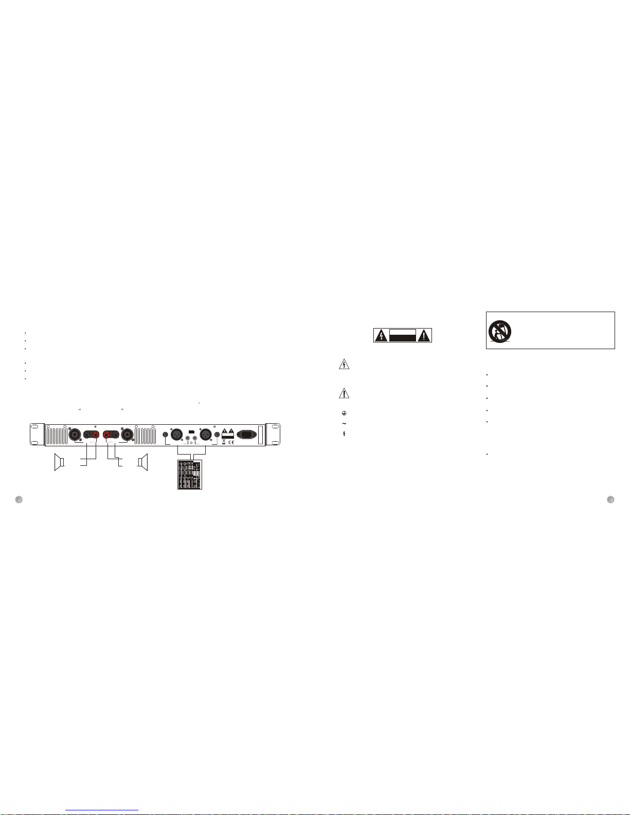
4. QUICK START
When operate the amplifier, please make sure:
Please check the AC voltage available in your country before connecting your amplifier to the AC socket.
All connections have been made correctly.
Set the volume control to a proper position. General, turn down the both volume control before switching on the amplifier for
avoiding damaging your loudspeaker system or excessive noise.
Turn on the amplifier via the power switch.
Then, adjust the volume slowly for getting the best signal to noise ratio.
After using, please turn off the device.
500W/400W/300W/200W professional power amplifier can be used in a wide variety of sound reinforcement applications.
When connecting the speaker, please pay attention to the speaker impedance. The speaker impedance will vary according
to the connection method and number of speaker. Please be sure that your speaker s impedance is not less than the relevant
Minimum value indicated SPECIFICATIONS chapter.
2
8
1
Use only with the cart, stand, tripod, bracket,
or table specified by the manufacturer, or
sold with the apparatus. When a cart is used,
use caution when moving the cart/apparatus
combination to avoid injury from tip-over.
Channel B
PIN 1+
PIN 1-
+
Channel A
PIN 1+
PIN 1-
+
CH A
OUTPUT
CH B
OUTPUT
CH A INPUT
CH B INPUT
CLIP
ON
OFF
-
+-+
CAUTION
RISK OF ELECTRIC SHOCK
DO NOT OPEN
AC~
12
3
12
3
Page 4
Cleaning
Clean only with a dry cloth. Do not use any solvents such
as benzol or alcohol.
Service
Do not implement any servicing other than those means
described in the manual.
Refer all servicing to qualified service personnel only.
Only use accessories/attachments or parts recommended
by the manufacturer.
Electrical Connection
Improper electrical wiring may invalidate the product warranty.
Power Cord and Plug
Protect the power cord from being walked on or pinched
particularly at plugs, convenience receptacles, and the point
where they exit from the apparatus. Do not defeat the safety
purpose of the polarized or grounding-type plug. A polarized
plug has two blades with one wider than the other. A grounding type plug has two blades and a third grounding prong.
The wide blade or the third prong is provided for your safety.
If the provided plug does not fit into your outlet, refer to electrician for replacement.
Power Supply
The apparatus should be connected to the power supply only
of the type as marked on the apparatus or described in the
manual. Failure to do could result in damage to the product
and possibly the user. Unplug this apparatus during lightning
storms or when unused for long periods of time.
Fuse
To prevent the risk of fire and damaging the unit, please use
only of the recommended fuse type as described in the manual.
Before replacing the fuse, make sure the unit turned off and
disconnected from the AC outlet.
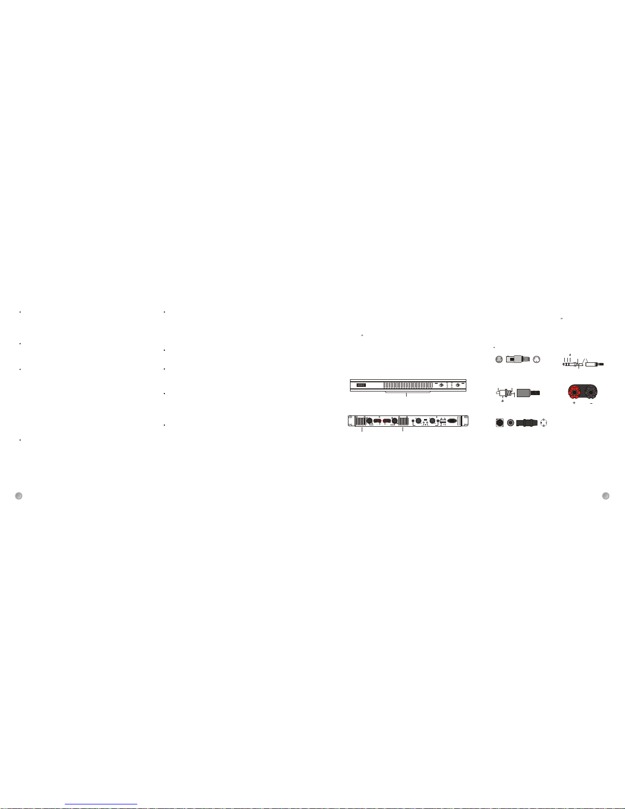
3. INSTALLATION AND CONNECTION
3.1 Installing in A Standard Rack
Intake hole
All models provide the variable fan for cooling the inside
temperature of amplifier.
The cooling fan draw air in from the front and exhaust it
through the rear. Please be sure that do not block the air
intakes or exhaust vents.
All models are standard 1U size, which can be mounted
in 19 standard rack with good ventilation. Please ensure
that there are enough space for cooling, and do not block
the ventilation, because the heat from the amplifier may
cause the interior of the amplifier to become very hot, in
this way, it will cause the performance of the amplifier to
be impaired.
Exhaust hole
Wiring configurations
3.2 Audio Connection
All models present with XLR, 1/4 phone jack, RCA and
binding post connectors, it can be interfaced by several
ways to support a variety of applications without any signal
loss.
XLR
11
22
33
11
22
33
1: GND 2: Hot (+) 3: Cold (-)
Tip
Ring
Sleeve
+
-
1/4" TRS JACK
+
Hot
Ground
RCA
Binding Post
3.3 Power Connection
Please ensure that the amplifier is set to the correct supply
voltage before plug the power cord into the wall outlet.
The mains connection of the amplifier is made by using
the enclosed mains cord and a standard IEC receptacle.
It meets the international safety certification requirements.
2
2
7
1+
1-2+2-
SPEAKON
Ventilation
Do not block areas of ventilation opening. Failure to do could
result in fire. Always install accordance with the manufacturer's
instructions.
Object and Liquid Entry
Objects do not fall into and liquids are not spilled into the
inside of the apparatus for safety.
OFF
CLIP
SIG
POWER
CH.A CH.B
dB
PROFESSIONAL POWER AMPLIFIER
ON
30
8
dB
30
8
CH A
OUTPUT
CH B
OUTPUT
CH A INPUT
CH B INPUT
CLIP
ON
OFF
-++
CAUTION
RISK OF ELECTRIC SHOCK
DO NOT OPEN
AC~
12312
3
Exhaust hole
Page 5

1. INTRODUCTION
Thank you very much for expressing your confidence in our product by purchasing 500W/400W/300W/200W professional
Power amplifier. The series of products are simple, conventional amplification facilities, which are based on many years
R&D experience and employ several advanced technologies, including clever clip limiter, short circuit protection, DC protection
and thermal protection and so on, these features can protect the amplifier from damage and /or overload. Besides,
500W/400W/300W/200W professional power amplifier also provided with following smart features:
Robust and compact design
Standard 1U rack size
Easy to operate front/rear panel control interface
Each channel provides SIGNAL LED, CLIP LED and POWER LED indicators
Volume control for each channel
Electronically balanced XLR, 6.3 jack and RCA input connectors
Binding post and Speakon output connectors
Protection circuit design (DC protection, short-circuit protection, thermal protection, overload protection, clip limiter)
Variable-speed low noise fan ensures high reliability even under demanding conditions
Light-weight for easier racking and shipping
In short, 500W/400W/300W/200W power amplifier is the optimum combination of performance, reliability and value in an
ultra-light weight package, all these features make it well suitable for small venue, studio/broadcast, recording and general
applications.
This manual covers the four models: 500W, 400W, 300W, 200W power amplifiers. Please read this manual carefully before
use, in such a way, you will get the best out of the amplifier and enjoy long and trouble-free operation
10. CLIP switch
Set this switch at ON position to activate the limiter circuit on output stage, once the output signal exceeds the rated power, the
CLIP limiter will compress the output signal to normal for protecting your speaker system from damage.
11. Ventilation
The ventilation is used to vent the heat. The built-in variable speed fans, serve to cool the internal temperature of amplifier for
reducing the noise.
Note: The fan operates at initial power-on, and the fan speed will vary automatically as the internal temperature changes.
7. AC Inlet socket
Standard 3-conductor type IEC power connector, serve to connect the amplifier to the mains supply via the enclosed power cord.
Please make sure the voltage available in your country and how the voltage for your amplifier is configured before attempting
to connect the mains supply.
Note: To prevent the risk of shock or fire hazard, always be sure that the amplifier and all associated equipment is properly
grounded.
8. Audio INPUT connectors
All models provide electronically balanced XLR (F), 1/4 phone jacks and unbalanced RCA connectors, designed for connection
of external audio signal.
For satisfying various connection requirements, it use low-noise, electronically balanced/unbalanced circuit, which can accept
balanced and unbalanced audio signal and offer a very wide dynamic range capable of handling virtually any signal level.
9. Audio OUTPUT connectors
Professional binding posts and Speakon connectors, serve to output the powered signal to external loudspeakers.
Note: Please make sure that the impedance does not fall below this specified impedance.
2
6
3
Page 6
2. CONTROL ELEMENTS
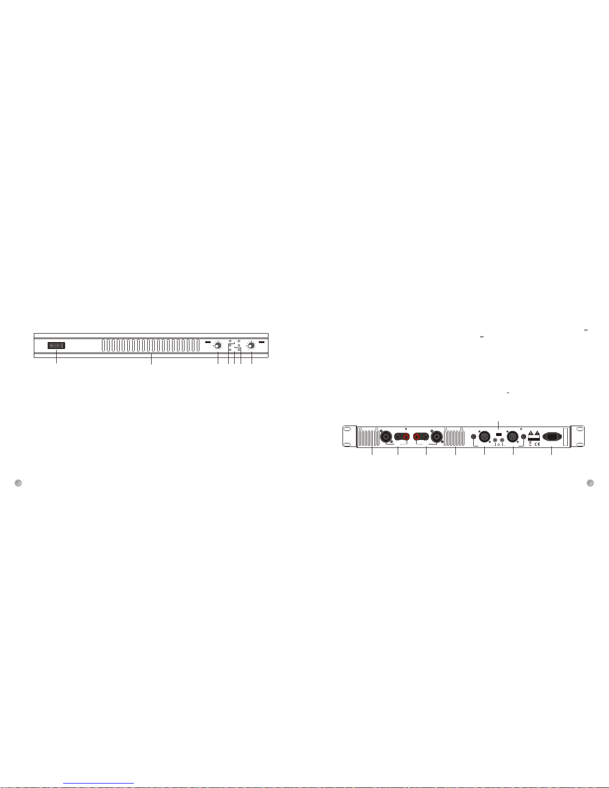
The front control elements of all models are identical, so we have used the 500W as the representation to assure simplicity.
2.1 Front Panel
1. POWER Switch
This is the main power switch, which is used to turn ON or OFF the amplifier. The POWER LED lights up when the amplifier is
turned ON.
Note: For avoiding damaging your device, please turn down the volume before turning on the power switch.
2. CLIP Indicator
The red LED indicator lights up when the corresponding channel's output signal reaches or exceeds the clipping level. Output
signal clipping is usually due to excessive input signal level.
3. SIG Indicator
Each channel provides a SIG LED indicator. These green LED indicators light up when the channel's output signal exceeds
500mV rms.
4. POWER Indicator
These blue LED indicators light up when the power switch is turned ON.
5. Volume Control
These volume controls are used to adjust the volume of corresponding channel (CHA or CHB) in 40 steps in the range of - dB
to 30dB. Turning the control fully counterclockwise is the off setting (- ), which is always a good idea to power up any new
installation for protecting the system loudspeakers from the damage.
6. Air Intake
The series of amplifiers use air cooling system. The cooling fan draw air in from the front and exhaust it through the rear.
Please be sure that the air intakes can not be blocked.
2.2 Rear Panel
The series of power amplifiers provide the identical panel, equip with balanced 1/4 TRS, XLR and unbalanced RCA input
connectors, and professional Binding post and speakon output connectors to make connections quick and easy.
For further details, please refer to following illustration:
2
4
5
1
3
4
2
5
6
5
OFF
CLIP
SIG
POWER
CH.A CH.B
dB
PROFESSIONAL POWER AMPLIFIER
ON
30
8
dB
30
8
89
10
11
7
89
11
CH A
OUTPUT
CH B
OUTPUT
CH A INPUT
CH B INPUT
CLIP
ON
OFF
-
+-+
CAUTION
RISK OF ELECTRIC SHOCK
DO NOT OPEN
AC~
12
3
12
3
Rear Panel illustration
 Loading...