

Page 1
OWNER’S MANUAL
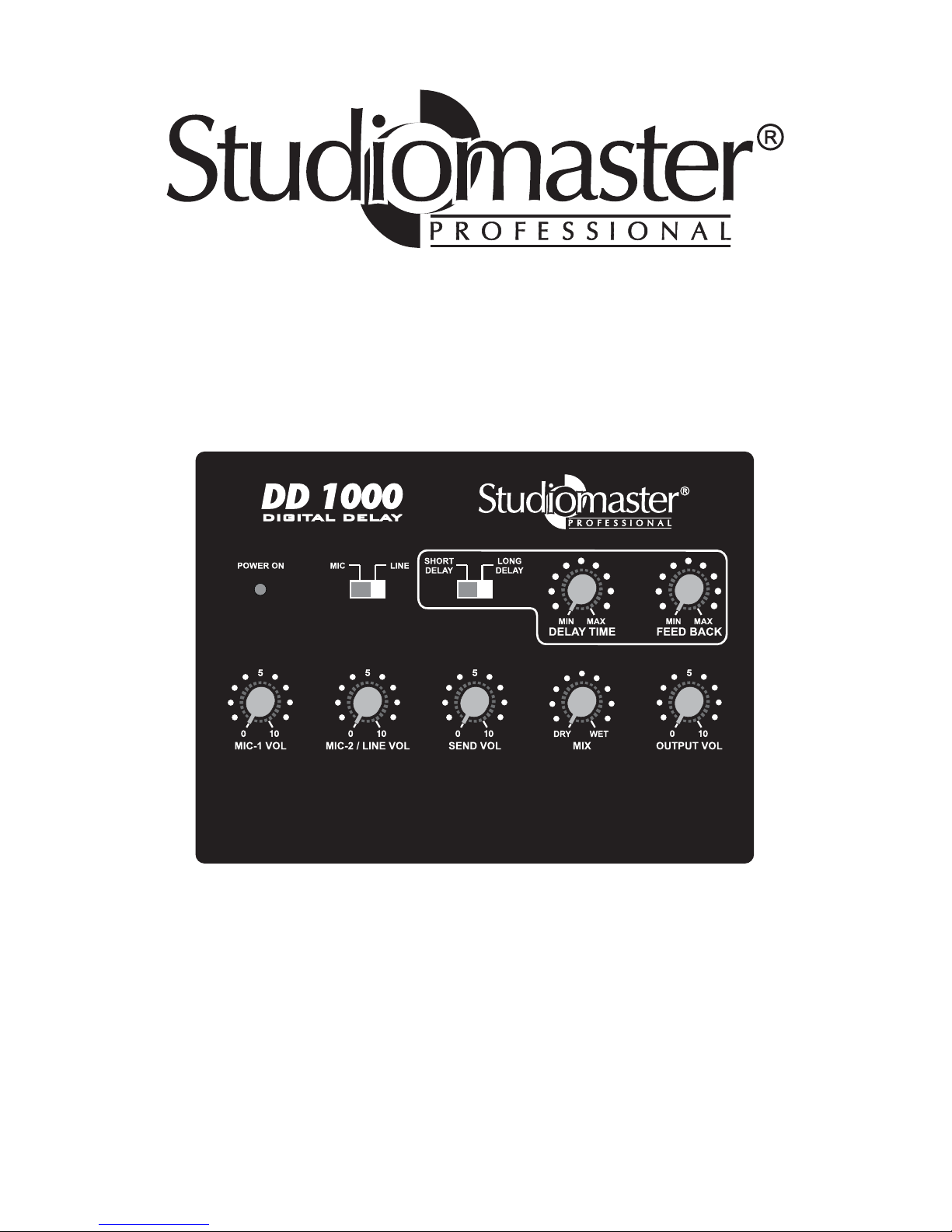
DD 1000
DIGITAL DELAY
Page 2

1
Safety Information
Operating Voltages
Unpacking your DD 1000
DD 1000 DIGITAL DELAY OPERATOR GUIDE
The DD 1000 is a digital delay module with Mic / Line mixer. Please read this manual
carefully before using the product. This guide contains important safety information,
operational instructions and service information.
Remove the DD1000 from the packing, and Warranty card. Keep the packing in the
eventuality that your DD1000 needs to be moved or returned for service or repair. Complete
and return your Warranty card. Returning the completed warranty card does not diminish
your statutory rights in any way.
Before plugging in the DD1000, please note that it is to be used with recommended DC
Power supply adapter only. DD1000 operates on +15VDC.
Features :
Do not use your DD1000 in environments having a very high humidity or where liquids
may accidentally enter the Unit. When powering up the system, switch on Power Amplifiers
after the Delay and any other connected equipment This will avoid any unexpected
loudspeaker thumps. If a fault occurs while operating the unit then return it to your dealer or to
an authorised service agency. Do not attempt to repair the DD1000 yourself as this could be
dangerous and will void the warranty.
Thank you, and Congratulations on your choice of the DD1000 Digital Delay. Before
starting out, please take the time to read through this manual. That way, you will better
understand every outstanding feature the unit provides, and can be assured of years or trouble
free service.
* DD1000 is designed to deliver delay sound with high performance.
* In built compander ensures distortion free sound.
* Delay is switched between Short Delay & Long Delay which gives various delay effects
with different setting of Delay Time and Feedback control.
* Two Mic and Line Input.
* Channel 2 is switchable between Mic and Line gives user option to use it in Mic.
* It can be used as stand-alone unit or with other mixer through Send/Return connector.
* Separate Direct output provided in addition to Effect Out.
* Level controls for Mic-1, Mic-2/Line, Send, Mix and Effect Output.
* Works on external +15VDC adapter.
* Elegant look.
Page 3
2
Protect the unit from strong impact. A small amount of heat will radiate from the unit
during normal operation. Before using the unit in a foreign country, consult with qualified service
personnel.
Additional Precations :
MIC-1 VOL MIC-2 / LINE VOL
SEND VOL
MIX OUTPUT VOL
POWER ON MIC LINE
LONG
DELAY
SHORT
DELAY
MIN MINMAX MAX
FEED BACKDELAY TIME
DRY WET
DD 1000
1
2
3
4
5
6
8
9
10
7
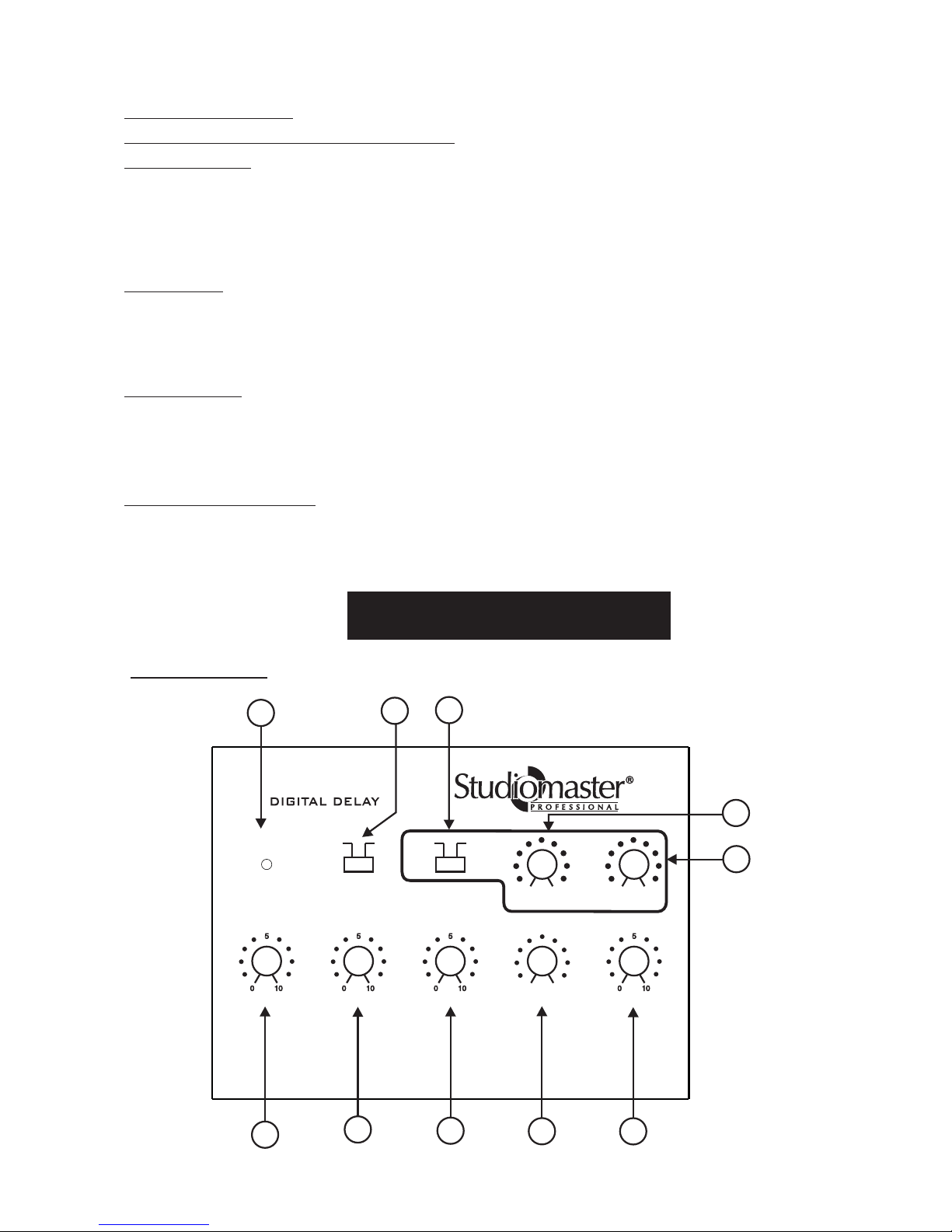
Front Panel
PANEL DESCRIPTIONS
For everyday cleaning wipe the unit with a soft, dry cloth or one that has been slightly
dampened with water. To remove stubborn dirt, use a mild, non-abrasive detergent.After wards
be sure to wipe the unit thoroughly with soft , dry cloth.
Before connecting this unit to other devices, turn off the power to all units; this will
help prevent damage or malfunction.
Do not use this unit on the same power circuit with any device that will generate line
noise; for example an electric motor or variable lighting system.
Using the unit near power amplifiers [or other equipment containing large power
transformers] may induce hum. This device may interfere with radiation and television
reception. Do not use this device in the vicinity of such receivers.
Placement :
Maintenance :
IMPORTANT NOTES
Please read and observe the following :
Power Supply :
Page 4

3
Switch Position
Delay Time
Min
Max
Short
136ms
440ms
Long
480ms 790ms
This controls the balance of the direct sound [input signal] respective to the effect (wet)
sound [the signal processed with the delay effect] that will be output. Rotating it
counter-clockwise increases the volume of the direct sound, while clockwise rotation
increases the volume of the effect (wet) sound. If you rotate the control fully counterclockwise or clockwise, respectively dry or dry+wetsound will be output.
*To connect the DD1000 to the Send/Return jacks on a mixing unit, be sure to
rotate the MIX control on the DD1000 fully clockwise i.e. to "wet" Position,
To get the applied Return Input at Effect Output Jack.
5. Output Level Control :
This knob is used for adjusting the output level of the unit turning it clockwise to get
the output level.
6. Power On Led :
This indicates the power on status of the unit.
7. Mic Line Switch :
This switch is used to select either MIC-2 or Line Input.
8. Short/Long Delay Switch :
This switch is used to select Short or Long delay
9. Delaytime Control :
This control adjusts the delay time [the time it will take for an echo to return]. Turning
the knob clockwise, make the delay time longer.
1. Mic-1 Level Control :
Controls the volume obtained with microphones connected to MIC Jack on rear
When not using the MIC jacks, turn the level control all the way down.
If howling occurs, rotate the level control counter-clockwise to lower the
volume.
2. Mic-2/Line Level Control :
Controls the volume obtained with microphones connected to MIC-2/Line Jack on
rear
When not using the MIC jacks, turn the level control all the way down.
If howling occurs, rotate the level control counter-clockwise to lower the
volume.
3. Send Level Control :
Controls the level going to SEND output.
4. Mix (Balance) Control :
10. Feedback Control :
This control adjusts the feedback amount [the number of repetitions] for the delay
sound [echo]. Turning the knob clockwise increases the number of repeatation.
As you turn up the FEEDBACK knob clockwise oscillation may occur. If this
happens turn the knob down until the oscillation stops.
Page 5
4
MIC-1MIC-2 / LINESEND / RETURN
DIRECT OUTEFFECT OUT
+15V DC
CAUTION:
USE ONLY RECOMMENDED
POWER SUPPLY
ON
OFF
SEND / RETURN
11
1213
1415
17
16
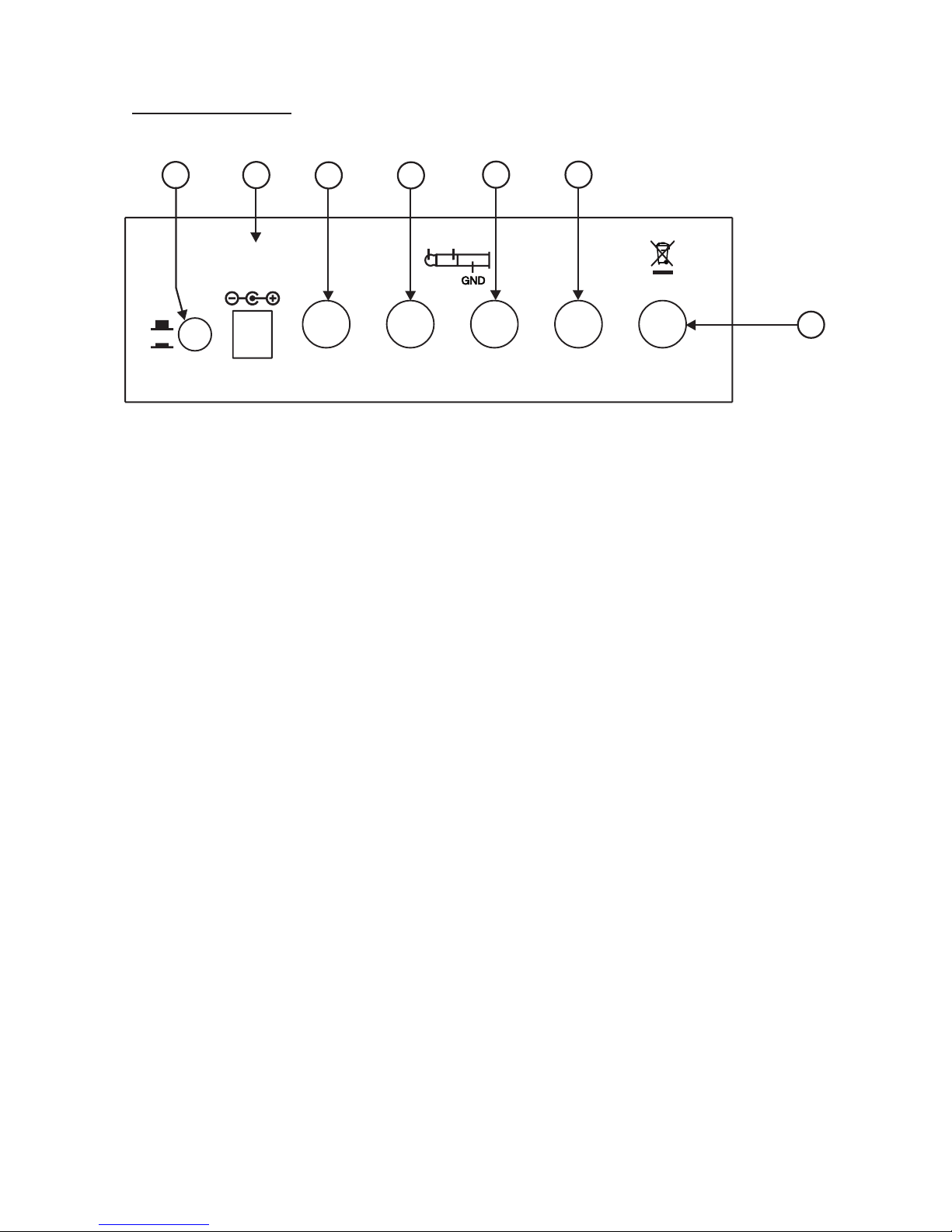
REAR PANEL
11. Mic-1 Jack Socket :
It is Stereo jack socket which accept connection of Balanced microphones.
12 Mic-2/Line Jack Socket :
It is Mono jack socket which accept connection of un-balanced microphone or Line,
depending on Mic/Line switch selection on front panel.
14. Direct Out Jack Socket :
This is used for connecting to the Power Amplifier or Mixer. The Pre-amplified Mic-1
and Mic-2/Line signal output is a available on this socket.
15. Effect Out :
This is used for connecting to the Power Amplifier or Mixer. The Pre-amplified Mic-1,
Mic-2/Line and Return Inputs Wet (effect) output signal is available on this socket.
16. Power Switch :
Press to switch on the unit. Release to switch it off. When turned on, the Power on led
light up.
17. Dc Socket :
This socket accept +15V DC. Please use only recommended power supply.
13. SEND / RETURN :
With Send/Return 6.3" stereo jack, DD 1000 can be patched with mixer using
it’s INSERT socket with single standard stereo cable.
RETURN
SEND
Page 6
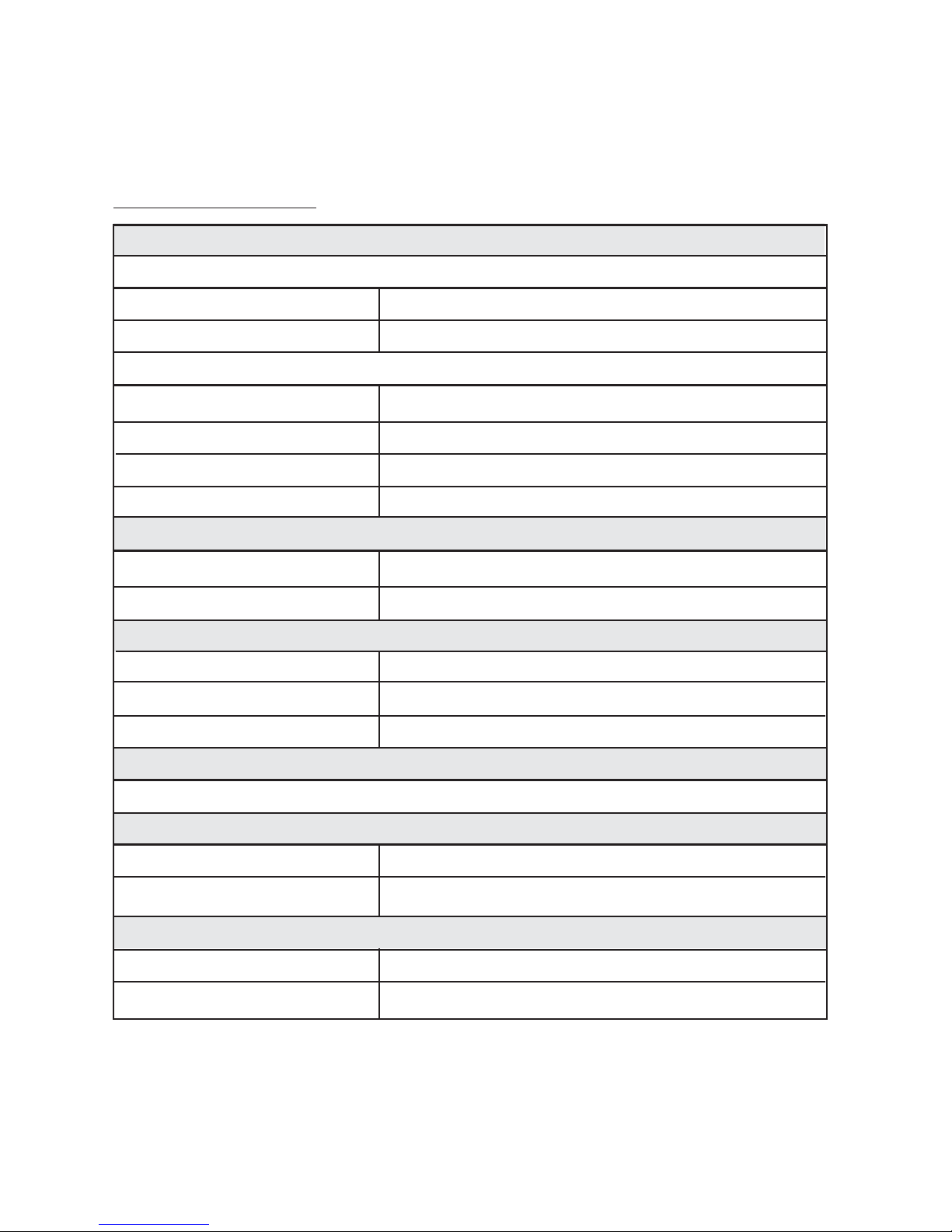
AUDIO INPUTS
MIC-1 Input (¼” Stereo Jack socket) :-
AUDIO OUTPUTS
Effect Out & Direct Out :-
SEND / RETURN (Output / Input)
DIGITAL ECHO PROCESSOR
Output Impedance : <40Ω
Send & Return :
Tip = , Ring = , Shield = Ground
Impedance : Send : <40
¼” Mono Jack socket, Unbalanced 775mV(0dBu)
Ω, Return : >10KΩ
Dual Chip Echo Processor Provide Minimum 136ms to Maximum 790ms Delay
Power Supply : 15V DC (External)
Current Consumption : 250mA max.
Dimensions : Approx. (WXDXH) 145x115x45mm
Weight : 0.7kg
POWER SUPPLY
DIMENSIONS/WEIGHT
Sensitivity : 1.5mVrms Balanced
Input impedance : >5k Ω
Mic-2 Sensitivity : 1.5mVrms (-54dbu) Unbalanced
Mic-2 Input Impedance : >5KΩ
Line I/P Sensitivity : 100mVrms (-17.5) Unbalanced
Line input impedance : >10KΩ
¼” Stereo Jack socket, Unbalanced 775mV(0dBu)
Return Send
(Output) (Input)
Mic-2 / Line Input (¼” Mono Jack socket) :-
SPECIFICATIONS:
5
Page 7

LITMA5F8 REV. 0
PRODUCT OF AUDIOPLUS
A1/A2, Giriraj Industrial Estate,
Mahakali Caves Road, Andheri (East),
Mumbai-400 093. India
Tel.: +91-22-66916232 / 33, 30880743,
30880776, 26870268 Fax: 26871453
Email: [email protected]
 Loading...