

Page 1
ADT
VOCAL1
S REV
VOCAL2
VOCAL3
L REV
PLATE1
PLATE2
REVERB
DELAY
REGEN
DSP ON
LEVEL
TO MON
MON LEVEL
POWER
+100dB-10-20
INPUT 5/6 - 7/8 - 9/10 - 11/12 DSP
MASTER
LO
60Hz
HI
LO
HI
12kHz
AUX/DSP
MON
LEVEL
EL
EL LEVEL
PRE
POST
9/10
11/12
01010
10 010
010
-
+
0
10
-
+
010010
010
010
1
0
m
s
2
5
0
m
s
7
2
0
m
s
INPUT 5/6 - 7/8 - 9/10 - 11/12
60Hz
12kHz
AUX
MON
LEVEL
EL
EL LEVEL
PRE
POST
9/10
11/12
MON LEVEL
POWER
+100dB-10-20
MASTER
010010
1010010
010
010
-
+
0
10
-
+
L
R
L
R
I
O
I
O
USER
GUIDE
3
C
3X
C
Page 2

1 Introduction
1 Read the User Guide
1 Unpacking
2 Safety Instructions
3-5 Controls & Features - Front panel
6-7 Controls & Features - Rear panel
8 DSP Effects List
8 Input Gain option
9 Trouble Shooting
10 Setup - Home Karaoke
11 Setup - Solo/Duo Performers
12 Setup - Pro Karaoke
13 Setup - Church System
14 Setup - Conference System
15 Technical Specification
16 Warranty
17 Service Information
3
C
C
3X
3
C
3X
C
INDEX
INDEX
www.studiomaster.com
www.studiomaster.com
Page 3

1
INTRODUCTION
Thank you for buying this Studiomaster product.
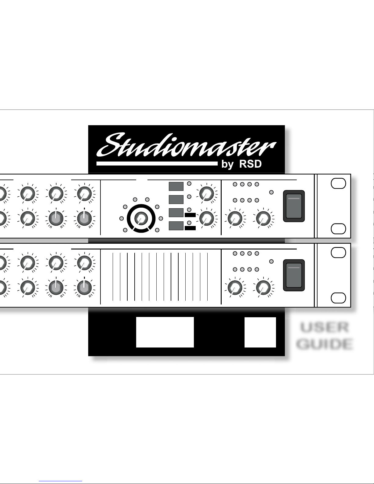
The C3 and C3X are compact, extremely versatile 12 input
audio mixers designed specifically for the requirements of
live sound.
They feature ultra quiet mic preamps, renowned
Studiomaster EQ and ease of use, all housed in a stylish
slim line rack mountable package.
The C3X also features Studiomaster's custom designed
DSP providing ultra clean reverbs and delay effects to
enhance the vocal performance.
READ THE USER GUIDE
Despite the sophisticated design the C3 and C3X are very
easy to use although to get the best from your new
purchase, we recommend you read this User Guide before
getting down to any serious work.
It also contains important safety information as well as
practical hints.
UNPACKING
Remove your Studiomaster product from its packaging
and ensure that along with this User Guide you have an
A.C. power cord / mains lead and a warranty card.
Retain the packing carton in the eventuality that the unit
needs to be returned for service or repair, and please
complete and return your warranty card. Returning the
completed warranty card does not diminish your statutory
rights in any way.
3
C
C
3X
3
C
3X
C
EXPECT THE BEST
EXPECT THE BEST
Page 4

2
1. Before connecting the A.C. power cord make sure the
Voltage selector (located on the side of the unit) is set
to your local supply voltage. For supplies between 220
and 240V use the 230V position. For supplies between
110 and 120V use the 115V position.
2. Only use the A.C. power cord / mains lead supplied
with the product. Replace if it becomes damaged in
any way.
3. Never operate without, or remove the safety ground
(earth) from the A.C. power cord / mains lead.
4. Do not attempt to remove any screws or panels.
There are no user serviceable parts inside.
5. Do not operate the unit next to heat sources such as
radiators.
6. The unit should not be operated or stored near rain or
moisture.
7. This equipment must not be exposed to dripping or
splashing and no objects filled with liquids should be
placed on top of it.
8. Write the serial number in the box provided in the
Warranty section for future reference.
9. If the unit gets damaged, has been dropped or appears
to have developed a fault refer to the Service
Information section for details.
WARNING
THIS APPARATUS MUST BE EARTHED (GROUNDED)
3
C
C
3X
3
C
3X
C
READ THIS BEFORE YOU USE YOUR PRODUCT
SAFETY INSTRUCTIONS
www.studiomaster.com
www.studiomaster.com
Page 5
3
Controls & Features - Front Panel
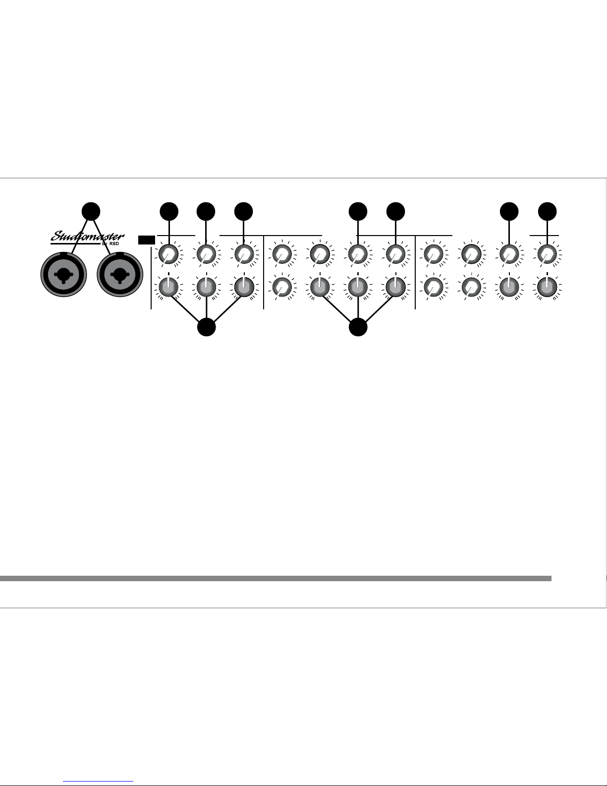
1. Input 1&2 : Combination XLR and Jack sockets
suitable for use with balanced low impedance microphones or
line level signals such as CD, keyboards, radio mics, or mini disc
players. 17V phantom power is available for suitable condenser
microphones via a switch located on the rear panel.
2. Input 1 level : Controls the volume level from Input 1.
3. Input 1, 2/3/4 EQ (tone control) section :
LO : 15dB of cut & boost at 60Hz
MID : 12dB of cut & boost at 2.5kHz
HI : 15dB of cut & boost at 12kHz
4. MON :
Adjusts the signal level feeding the MON (monitor) output. This is
useful for creating a separate mix of sound for on stage
monitoring or headphone amplifiers. Adjustment of the input level
control will not affect the signal going to the MON output, as this
signal is derived before (pre) the input level control.
5a. AUX (C3 only) :
Adjusts the signal level feeding the AUX (auxiliary) output. This is
useful for creating a separate mix of sound to feed external
effects processors such as reverb or delay units. The signal to
the control is derived after (post) the input level, so any
adjustment will affect the mix going to the AUX output.
5b. AUX/DSP (C3X only) :
Adjusts the signal level feeding the AUX (auxiliary) output and
the internal DSP (digital signal processor) section. This is useful
for creating a separate mix of sound to feed the DSP or external
effects units. The signal to the control is derived after (post) the
input level so any adjustment will affect the mix going to the AUX
output.
1 2 4 5 4 5 4 5
3 3
MID
2.5kHz
HI
12kHz
MON
LEVEL
INPUT 1
INPUT 1 INPUT 2
12 Input Mic / Line Mixer with DSP
3X
C
PRE
POST
LO
60Hz
AUX/DSP
INPUT 2/3/4
HI
12kHz
LEVELLEVEL
LEVEL
24
3
INPUT 5/6 - 7/8 - 9/10 - 11/12
LO
60Hz
MID
2.5kHz
AUX/DSP
MON
PRE
POST
LO
60Hz
HI
12kHz
AUX/DSP
MON
LEVELLEVEL
5/6
LEVEL LEVEL
PRE
POST
9/10
7/8
11/12
010
-
+
010
-
+
0
10
-
+
010010
010
-
+
010
-
+
0
10
-
+
010010
010010
010
-
+
0
10
-
+
EXPECT THE BEST
EXPECT THE BEST
Page 6
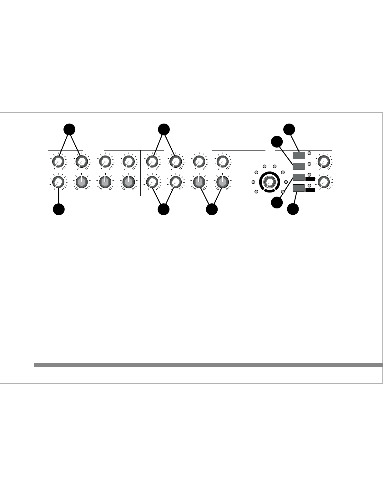
6. Input level controls 2, 3 & 4 :
Controls the volume level from their respective inputs located on
the rear panel. These inputs share MON, AUX and EQ controls.
7. Stereo Input level controls 5/6, 7/8, 9/10 & 11/12 :
Controls the volume level from their respective inputs located on
the rear panel.
8. Stereo Input EQ (tone control) section :
LO : 15dB of cut & boost at 60Hz
HI : 15dB of cut & boost at 12kHz
9. DSP (digital signal processor) section (C3X only) :
a) On/Off switch :
Turns on or off the output from the DSP. The LED illuminates
when on. This function can also be controlled by a foot switch see rear panel section for details.
b) REVERB switch :
This sets the DSP to reverb mode and illuminates the adjacent
LED. Use the rotary encoder to select the effect required. One of
the 8 LEDs surrounding the encoder shows the selection made.
c) DELAY switch :
This sets the DSP to delay mode and illuminates the adjacent
LED. The encoder is now used to increase or decrease the delay
or repeat time between 10mS and 720mS. This is displayed by
the LEDs surrounding the encoder.
d) REGEN switch :
If selected when in DELAY mode this effect adds a percentage of
the output back to the input signal and can be increased or
decreased depending on the position of the encoder. In this
mode the LEDs surrounding the encoder now display the amount
of regen applied.
NOTE : To return to DELAY mode, REGEN must be turned off.
4
6 7
9a
9b
9c
9d
6 7 8
INPUT 2/3/4
HI
12kHz
LEVELLEVEL
LEVEL
24
3
ADT
VOCAL1
S REV
VOCAL2
VOCAL3
L REV
PLATE1
PLATE2
REVERB
DELAY
REGEN
DSP ON
LEVEL
TO MON
INPUT 5/6 - 7/8 - 9/10 - 11/12 DSP
LO
60Hz
MID
2.5kHz
AUX/DSP
MON
PRE
POST
LO
60Hz
HI
12kHz
AUX/DSP
MON
LEVELLEVEL
5/6
LEVEL LEVEL
PRE
POST
9/10
7/8
11/12
010010
010
-
+
010
-
+
0
10
-
+
010010
010010
010
-
+
0
10
-
+
010
010
1
0
m
s
2
5
0
m
s
7
2
0
m
s
www.studiomaster.com
www.studiomaster.com
www.studiomaster.com
Page 7
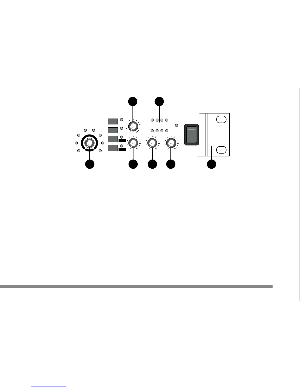
e) Rotary Encoder :
Used to select the program required in REVERB or DELAY
modes.
f) DSP LEVEL :
Adjusts the level of the effect from the DSP to the MASTER
output.
g) DSP TO MON :
Adjusts the level of the effect from the DSP to the MON output.
This is useful for adding reverb or delay effects to the stage
monitor or headphone mix.
Note : The last selection made in reverb and delay mode will be
remembered next time the unit is turned on.
10. MASTER level :
This controls the output volume to the external amplifier and / or
recorder.
11. MON LEVEL :
This adjusts the volume sent to the MON output.
12. Bargraphs :
Left and right 4 segment LED display showing the output signal
level.
13. Rack mounting brackets :
The unit is supplied ready for installation into a standard 19"
rack. For free standing use, remove the 3 philips screws on each
bracket. Retain the brackets and screws for future use.
5
9f
9e 9g 11
12
10 13
ADT
VOCAL1
S REV
VOCAL2
VOCAL3
L REV
PLATE1
PLATE2
REVERB
DELAY
REGEN
DSP ON
LEVEL
TO MON
MON LEVEL
POWER
+100dB-10-20
DSP
MASTER
010010
010
010
1
0
m
s
2
5
0
m
s
7
2
0
m
s
L
R
I
O
EXPECT THE BEST
EXPECT THE BEST
EXPECT THE BEST
Page 8
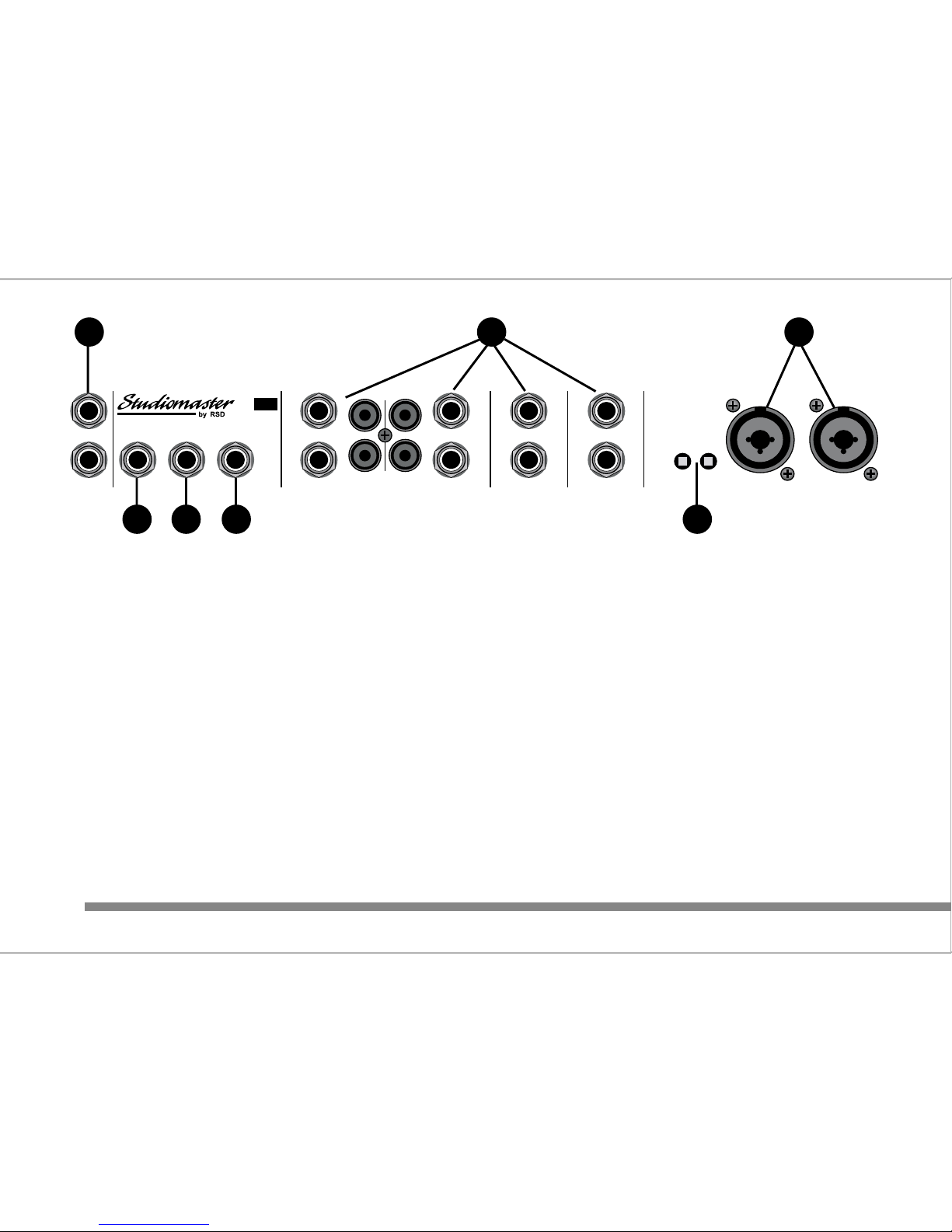
6
Controls & Features - Rear Panel
1. Input 3&4 : Combination XLR and Jack sockets
suitable for use with balanced low impedance microphones or
line level signals such as CD, keyboards, radio mics, or mini disc
players. 17V phantom power is available for suitable condenser
microphones via the adjacent switch.
2. +17V Phantom Power Switches :
For use with suitable condensor microphones. Most modern
condensor microphones have a working voltage range of 9 to
50V. However, if in doubt check with the microphone
manufacturer.
3. Stereo Inputs 5/6, 7/8, 9/10 & 11/12 :
1/4" Jack sockets for use with balanced or unbalanced line level
signals. If a mono signal is used, connect to the left input which
will automatically feed the signal into both the left and right
inputs. Inputs 9/10 and 11/12 have additional RCA 'phono' input
connectors suitable for unbalanced signals.
4. DSP ON/OFF Footswitch (C3X only) :
TS 1/4" Jack socket for the connection of an external footswitch
(not supplied). The DSP section can be turned on and off by the
footswitch. A latching on/off type footswitch should be used.
5. MON output :
TRS 1/4" balanced compatible output. Use 3 pole TRS or 2 pole
TS jack plugs.
6. AUX output :
TRS 1/4" balanced compatible output. Use 3 pole TRS or 2 pole
TS jack plugs.
7. INSERT :
TRS 1/4" jack socket send and return. Ideal for connecting
137
2456
www.studiomaster.com
www.studiomaster.com
INPUT 3INPUT 4
+17V
PHANTOM
INPUT
5/6
INPUT
7/8
INPUT
9/10
INPUT
11/12
LEFT
RIGHT
LEFT LEFT
/MONO
RIGHT RIGHT RIGHT
MON
DSP ON/OFF
FOOTSWITCH
AUX
INSERT
www.studiomaster.com
3-41-2
LEFT
RIGHT
LEFT
RIGHT
3X
C
LEFT
/MONO
Page 9
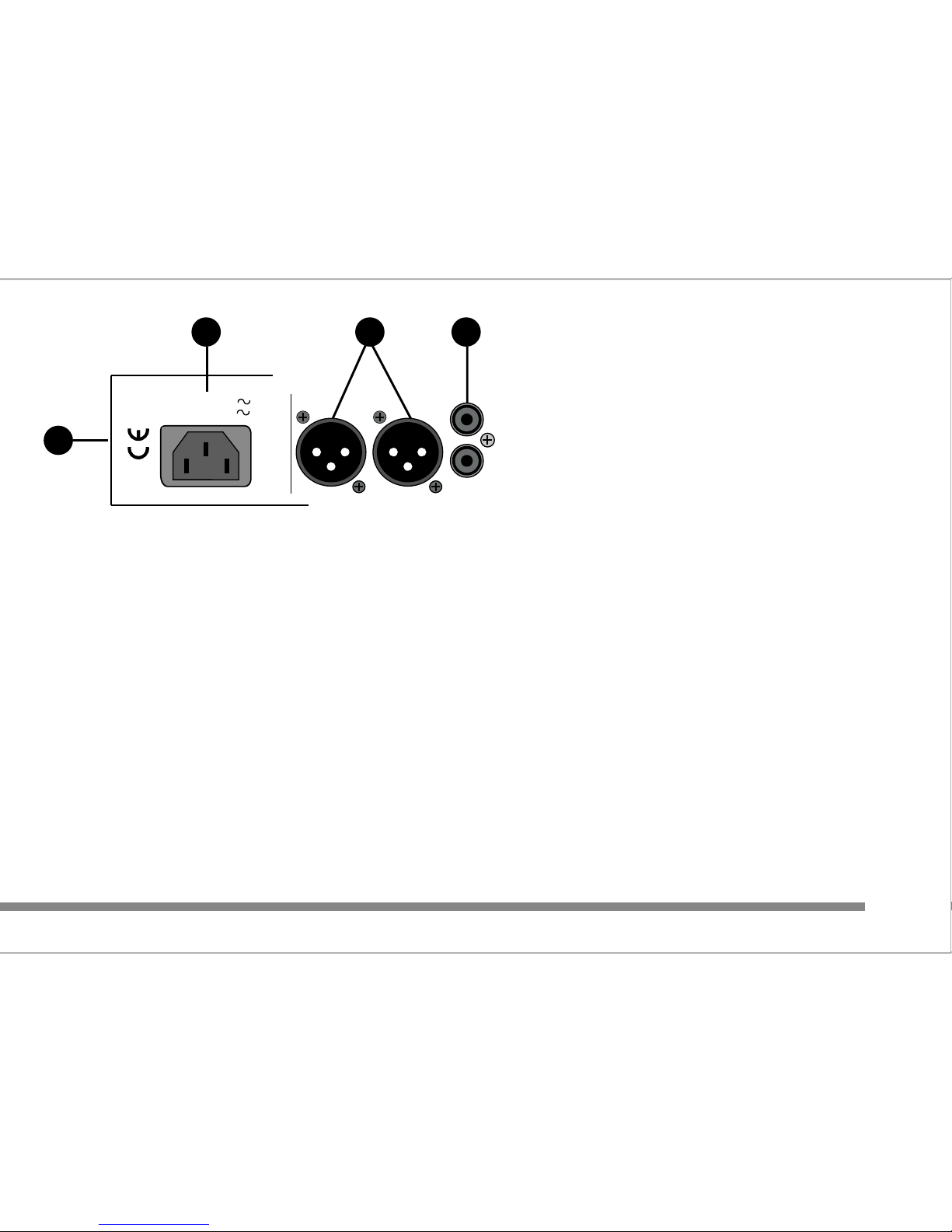
7
external processors like graphic equalisers in the main left and
right signal prior to the MASTER volume control.
8. LEFT and RIGHT RCA phono outputs :
Unbalanced signal suitable for HI-FI amplifiers and recorders.
9. LEFT and RIGHT balanced XLR outputs :
Balanced signal suitable for professional amplifiers and sound
systems.
10. AC Power Input.
11. Voltage Selector (located on the side panel) :
Do not adjust this switch when the A.C. power cord / mains lead
is connected. For supplies between 220 and 240V use the 230V
position. For supplies between 110 and 120V use the 115V
position.
9 8
10
11
EXPECT THE BEST
EXPECT THE BEST
OUTPUT
LEFTRIGHT
MASTER OUTPUTS
LEFT
RIGHT
230V Range : 50/60Hz 70mA
115V Range : 50/60Hz 140mA
DESIGNED AND ENGINEERED
BY RSD IN ENGLAND
ASSEMBLED IN CHINA
Page 10
Reverb Mode
VOCAL1 Reverb with medium delay
VOCAL2 Reverb with short delay
VOCAL3 Reverb with long delay
ADT 25mS delay with ambient reverb
S REV Small room reverb
L REV Large hall reverb
PLATE1 Short plate reverb
PLATE2 Medium plate reverb
Delay Mode
Variable between 10mS to 720mS
Regen
Variable between 10% to 90%
8
3
C
C
3X
3
C
3X
C
DIGITAL SIGNAL PROCESSOR
DSP EFFECTS LIST
SERVICE CENTRES ONLY
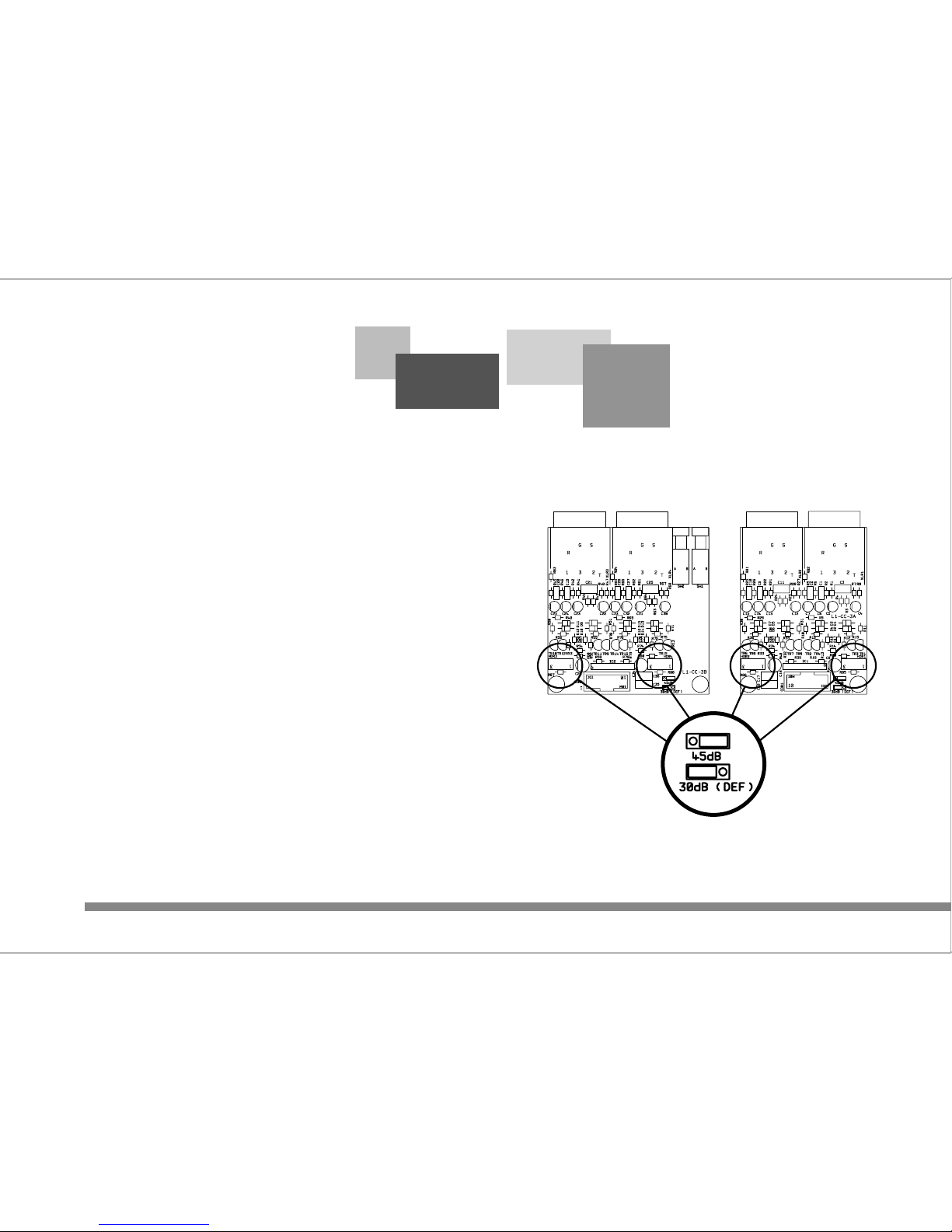
INPUT GAIN OPTION
www.studiomaster.com
www.studiomaster.com
www.studiomaster.com
IMPORTANT
This option should
only be implemented
by an authorised
Studiomaster dealer
or service centre.
Mic and Line input
gains can be
increased by 15dB.
This is internally
selectable on each
mic preamp PCB by
moving the relevant
jumper plug as shown
above.
Page 11

9
No Power On Led.....
Check A.C. power cord/mains lead is connected to wall
supply and switched on.
UK only - Check fuse in mains plug.
Check A.C. power cord/mains lead is fully pushed into the
rear panel socket
Check the unit is switched on, and blue power on LED is
illiuminated.
No sound.....
Check for a signal on the meters.
Check the amplifier and speaker system is connected and
switched on.
Check that the level control of the channel being used and
the MASTER OUTPUT level control are not set at '0'
position.
Check the sound source - is it on?
3
C
C
3X
3
C
3X
C
WHY IS IT NOT WORKING!
TROUBLE SHOOTING
EXPECT THE BEST
EXPECT THE BEST
EXPECT THE BEST
Page 12
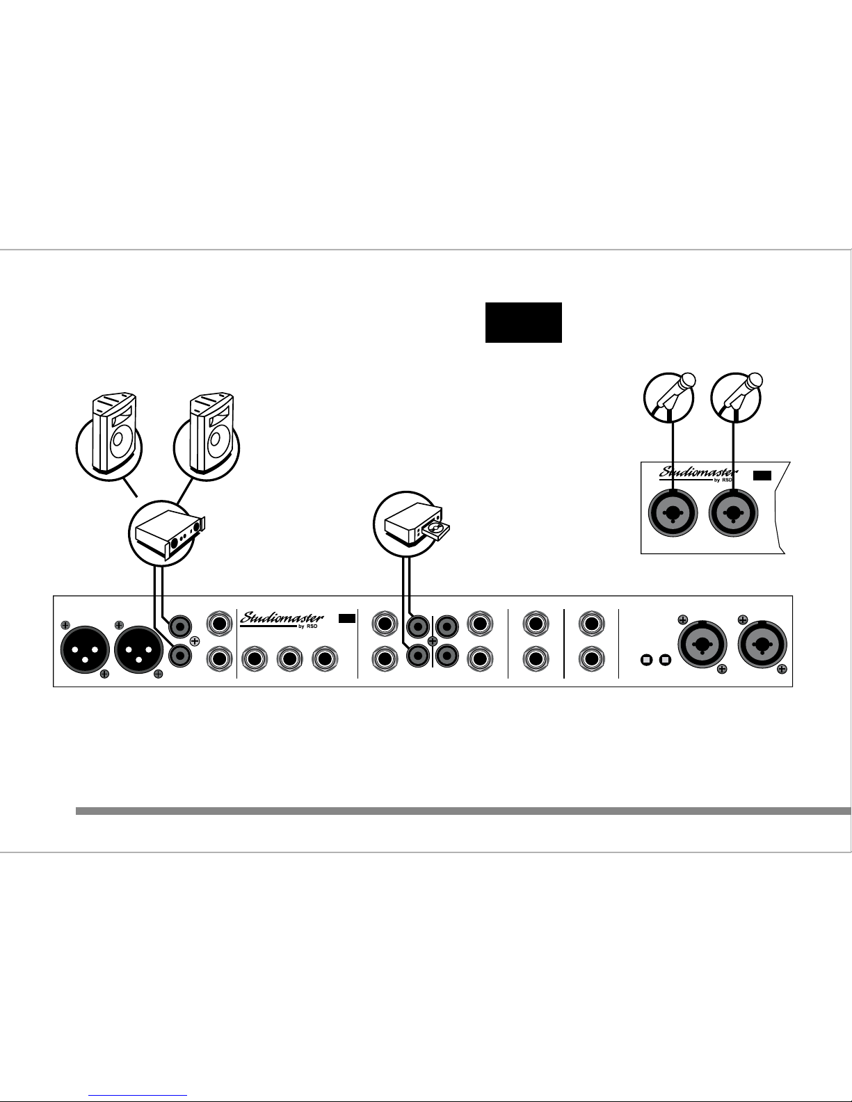
H
I
-
F
I
A
M
P
L
I
F
I
E
R
S
P
E
A
K
E
R
S
S
P
E
A
K
E
R
S
M
I
C
R
O
P
H
O
N
E
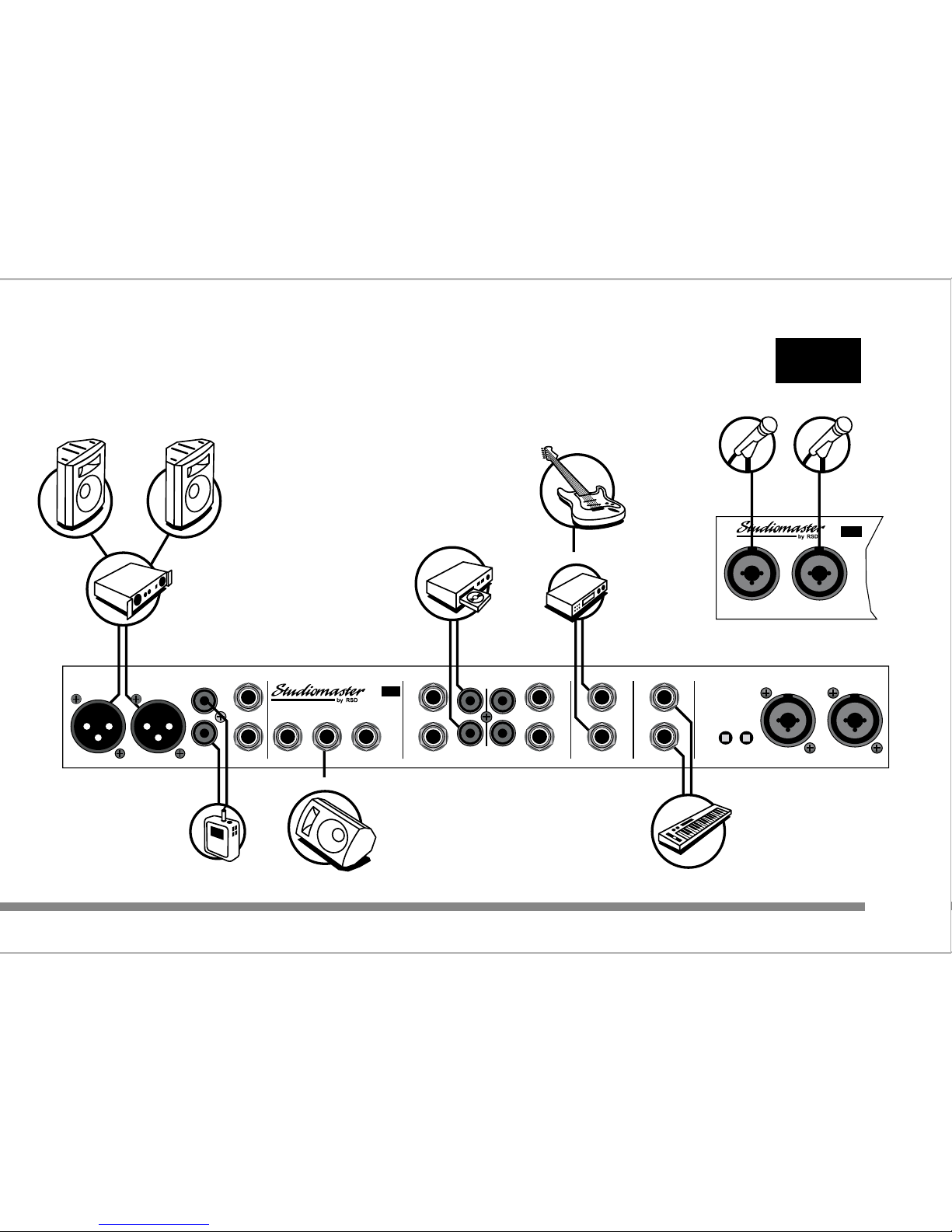
1
INPUT 1 INPUT 2
12 Input Mic / Line Mixer with DSP
3X
C
M
I
C
R
O
P
H
O
N
E
2
K
A
R
A
O
K
E
M
A
C
H
I
N
E
C
D
/
C
D
G
P
L
A
Y
E
R
HOME KARAOKE
HOME KARAOKE
3X
C
10
www.studiomaster.com
www.studiomaster.com
INPUT 3
INPUT 4
+17V
PHANTOM
INPUT
5/6
INPUT
7/8
INPUT
9/10
INPUT
11/12
LEFT
RIGHT
LEFT LEFT
/MONO
RIGHT RIGHT RIGHT
MON
DSP ON/OFF
FOOTSWITCH
AUX
INSERTOUTPUT
www.studiomaster.com
LEFTRIGHT
MASTER OUTPUTS
3-41-2
LEFT
RIGHT
LEFT
RIGHT
3X
C
LEFT
/MONO
Page 13
11
EXPECT THE BEST
EXPECT THE BEST
P
E
R
F
O
R
M
E
R
1
INPUT 1 INPUT 2
12 Input Mic / Line Mixer with DSP
3X
C
P
E
R
F
O
R
M
E
R
2
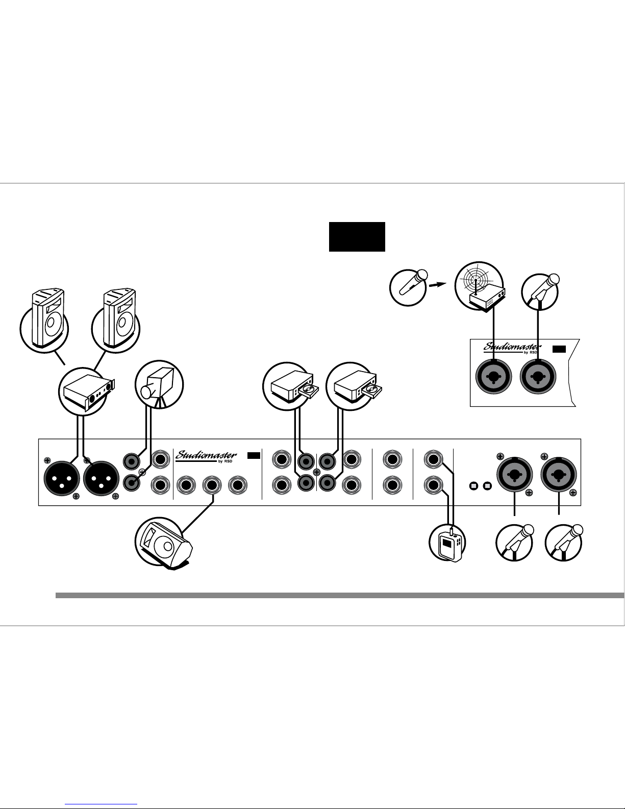
SOLO / DUO PERFORMERS
SOLO / DUO PERFORMERS
3X
C
S
P
E
A
K
E
R
S
S
P
E
A
K
E
R
S
A
M
P
L
I
F
I
E
R
B
A
C
K
I
N
G
T
R
A
C
K
/
D
R
U
M
M
A
C
H
I
N
E
S
T
A
G
E
M
O
N
I
T
O
R
S
MD
R
E
C
O
R
D
E
R
2
T
R
A
C
K
P
R
O
C
E
S
S
O
R
G
U
I
T
A
R
K
E
Y
B
O
A
R
D
INPUT 3INPUT 4
+17V
PHANTOM
INPUT
5/6
INPUT
7/8
INPUT
9/10
INPUT
11/12
LEFT
RIGHT
LEFT LEFT
/MONO
RIGHT RIGHT RIGHT
MON
DSP ON/OFF
FOOTSWITCH
AUX
INSERTOUTPUT
www.studiomaster.com
LEFTRIGHT
MASTER OUTPUTS
3-41-2
LEFT
RIGHT
LEFT
RIGHT
3X
C
LEFT
/MONO
Page 14
A
M
P
L
I
F
I
E
R
S
P
E
A
K
E
R
S
S
P
E
A
K
E
R
S
INPUT 1 INPUT 2
12 Input Mic / Line Mixer with DSP
3X
C
P
E
R
F
O
R
M
E
R
1
C
D
/
C
D
G
P
L
A
Y
E
R
1
C
D
/
C
D
G
P
L
A
Y
E
R
2
P
E
R
F
O
R
M
E
R
3
P
E
R
F
O
R
M
E
R
2
12
www.studiomaster.com
www.studiomaster.com
www.studiomaster.com
3X
C
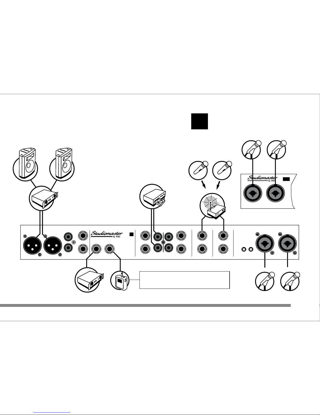
PRO KARAOKE
PRO KARAOKE
V
I
D
E
O
S
O
U
N
D
T
R
A
C
K
R
E
C
O
R
D
C
O
M
P
E
R
E
M
I
C
W
I
R
E
L
E
S
S
R
E
C
E
I
V
E
R
MD
P
L
A
Y
E
R
C
D
/
M
I
N
I
D
I
S
C
S
T
A
G
E
M
O
N
I
T
O
R
S
INPUT 3
INPUT 4
+17V
PHANTOM
INPUT
5/6
INPUT
7/8
INPUT
9/10
INPUT
11/12
LEFT
RIGHT
LEFT LEFT
/MONO
RIGHT RIGHT RIGHT
MON
DSP ON/OFF
FOOTSWITCH
AUX
INSERTOUTPUT
www.studiomaster.com
LEFTRIGHT
MASTER OUTPUTS
3-41-2
LEFT
RIGHT
LEFT
RIGHT
3X
C
LEFT
/MONO
Page 15
13
EXPECT THE BEST
EXPECT THE BEST
EXPECT THE BEST
S
P
E
A
K
E
R
S
S
P
E
A
K
E
R
S
A
L
T
A
R
M
I
C
INPUT 1 INPUT 2
12 Input Mic / Line Mixer with DSP
3X
C
C
O
N
G
R
E
G
A
T
I
O
N
M
I
C
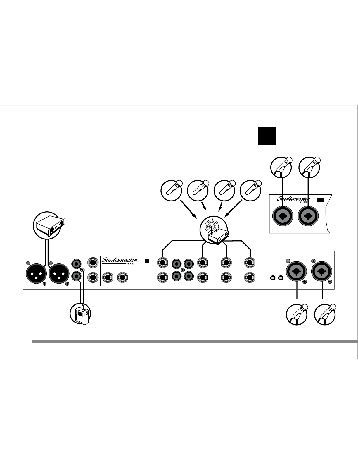
CHURCH SYSTEM
CHURCH SYSTEM
3
C
O
V
E
R
H
E
A
D
C
H
O
I
R
M
I
C
1
O
V
E
R
H
E
A
D
C
H
O
I
R
M
I
C
2
M
D
R
A
D
I
O
M
I
C
1
R
A
D
I
O
M
I
C
2
W
I
R
E
L
E
S
S
R
E
C
E
I
V
E
R
R
E
C
O
R
D
E
R
A
M
P
L
I
F
I
E
R
C
D
P
L
A
Y
E
R
A
M
P
L
I
F
I
E
R
I
N
D
U
C
T
I
O
N
L
O
O
P
www.studiomaster.com
INSERTOUTPUT
LEFT
RIGHT
INPUT 3INPUT 4
+17V
PHANTOM
INPUT
5/6
INPUT
7/8
INPUT
9/10
INPUT
11/12
LEFT
RIGHT
LEFT LEFT
/MONO
LEFT
/MONO
RIGHT RIGHT RIGHT
MON
AUX
LEFTRIGHT
MASTER OUTPUTS
3-41-2
LEFT
RIGHT
3
C
By routing the congregation mic ONLY to the MON
output, and not to the main output the whole service
(including the congregation) can be recorded.
Page 16
M
I
C
R
O
P
H
O
N
E
1
INPUT 1 INPUT 2
12 Input Mic / Line Mixer with DSP
3X
C
M
I
C
R
O
P
H
O
N
E
2
CONFERENCE SYSTEM
CONFERENCE SYSTEM
3
C
A
M
P
L
I
F
I
E
R
M
I
C
R
O
P
H
O
N
E
4
M
I
C
R
O
P
H
O
N
E
3
M
D
R
A
D
I
O
M
I
C
5
R
A
D
I
O
M
I
C
6
R
A
D
I
O
M
I
C
7
R
A
D
I
O
M
I
C
8
W
I
R
E
L
E
S
S
R
E
C
E
I
V
E
R
R
E
C
O
R
D
E
R
2
T
R
A
C
K
TOTAL OF 8 MICROPHONES
14
www.studiomaster.com
www.studiomaster.com
www.studiomaster.com
INSERTOUTPUT
LEFT
RIGHT
INPUT 3INPUT 4
+17V
PHANTOM
INPUT
5/6
INPUT
7/8
INPUT
9/10
INPUT
11/12
LEFT
RIGHT
LEFT LEFT
/MONO
LEFT
/MONO
RIGHT RIGHT RIGHT
MON
AUX
LEFTRIGHT
MASTER OUTPUTS
3-41-2
LEFT
RIGHT
3
C
Page 17

3
C
C
3X
3
C
3X
C
15
EXPECT THE BEST
EXPECT THE BEST
FACTS & FIGURES
TECHNICAL SPECIFICATION
Maximum Gain (Input to Output)
Mic Inputs 55dB
Line Inputs 40dB
Stereo Inputs 24dB
Frequency Response (any Input) 22Hz - 40kHz
Distortion (any Input) 0.03%
Equalisation (all +/-15dB)
Mic Input LO 60Hz
MID 2.5kHz
HI 12kHz
Stereo Input LO 60Hz
HI 12kHz
DSP (C3X only)
Reverb mode 8 Programs - see DSP Effects list
Delay mode Variable between 10mS to 720mS
Regen Variable between 10% to 90%
Input Connectors Mic Balanced XLR
Line Balanced TRS Jack
Stereo 5/6 & 7/8 Balanced TRS Jack
Stereo 9/10 & 11/12 Balanced TRS Jack and
unbalanced RCA phono
Output Connectors Master Outputs Balanced XLR and
unbalanced RCA phono
Aux Balanced compatible TRS Jack
Mon Balanced compatible TRS Jack
DSP footswitch (C3X only) TS Jack
Power Requirements C3
230V range +/-10%, ~50/60Hz, 52mA Max
115V range +/-10%, ~50/60Hz, 104mA Max
C3X
230V range +/-10%, ~50/60Hz, 70mA Max
115V range +/-10%, ~50/60Hz, 140mA Max
Dimensions Width 482mm (19") including rack ears
Height 44mm (1.75") 1U
Depth 265mm (10.5")
Weight
C3 Net 3.6KG (7.92lbs) Gross 4.6KG (10.12lbs)
C3X Net 3.7KG (8.14lbs) Gross 4.7KG (10.34lbs)
Page 18

The Manufacturer warrants all Studiomaster products to be free
from defects in materials and workmanship for a period of one
year from date of purchase. The Manufacturer reserves the right
to the final decision on all warranty claims.
Exclusions to Warranty Cover
Damage caused by accident, misuse, improper
installation or neglect.
Damage caused by repair, modification or service by
persons not authorised by Studiomaster.
Products on which the serial number has been
defaced, altered or removed.
Who is Protected
This warranty is enforceable by the original purchaser and any
subsequent owner(s) during the warranty period, providing a
copy of the original sales receipt is submitted whenever a
warranty service is required.
It is recommended that you complete and mail the Warranty
Registration Card supplied with your product.
For your reference in the event of a warranty or service repair,
please complete the following information and attach a copy or
your original sales receipt.
Model :
Serial Number :
Purchase Date :
Purchased From :
Note : THIS WARRANTY DOES NOT AFFECT YOUR
STATUTORY RIGHTS
3
C
C
3X
3
C
3X
C
16
www.studiomaster.com
www.studiomaster.com
www.studiomaster.com
ARE YOU COVERED?
WARRANTY
Page 19

If you have a problem with your Studiomaster product or think it
has developed a fault you should first carefully check the Trouble
Shooting section in this guide. If this does not solve the problem
or if the product is physically damaged, contact your local dealer
or distributor for service details.
Should it be recommended you return the product to your
nearest Studiomaster Service Centre you must first contact
them.
You will be asked for the product type and serial number. You
will then be given a Returns Authorisation (RA) number.
Pack the unit in its original carton to protect it from shipping
damage.
You must have the Returns Authorisation number clearly marked
on the outside of the carton or we may refuse the delivery.
Studiomaster cannot be held responsible for damage resulting
from the equipment being packed incorrectly.
Label the equipment clearly with your name and address and
include a clear description of the fault. The more information you
supply helps the service engineer, minimising repair cost when
out of warranty.
Important : No liability will be accepted by Studiomaster for any
transit damage to units not returned in their original packing, for
warranty repairs or otherwise.
3
C
C
3X
3
C
3X
C
17
EXPECT THE BEST
EXPECT THE BEST
EXPECT THE BEST
In Accordance with our progressive product development, Studiomaster / Recording Studio Design
reserve the right to change features and specifications without prior notice.
HOW TO GET MY PRODUCT REPAIRED
SERVICE INFORMATION
Page 20
MID
2.5kHz
HI
12kHz
MON
LEVEL
INPUT 1
INPUT 1 INPUT 2
12 Input Mic / Line Mixer with DSP
3X
C
PRE
POST
LO
60Hz
AUX/DSP
INPUT 2/3/4
HI
12kHz
LEVELLEVEL
LEVEL
24
3
LO
60Hz
MID
2.5kHz
AUX/DSP
MON
PRE
POST
MID
HI
LO
HI
LO
MID
LE
V
5/6
LE
V
7/8
010
-
+
010
-
+
0
10
-
+
010010
010
-
+
010
-
+
0
10
-
+
0
0
60Hz
2.5kHz
12kHz
AUX
MON
LEVEL
INPUT 1
INPUT 1 INPUT 2
12 Input Mic / Line Mixer
3
C
POST
PRE
INPUT 2/3/4
12kHz
LEVELLEVEL
LEVEL
24
3
60Hz
2.5kHz
AUX
PRE
POST
LE
V
5/6
LE
V
7/8
MON
010
-
+
010
-
+
0
10
-
+
010
010
010
-
+
010
-
+
0
10
-
+
0
0
www.studiomaster.com
Recording Studio Design Limited
7 Eden Way, Pages Industrial Park, Leighton Buzzard, Bedfordshire LU7 4TZ UK
Tel : 44 (0)1525 217111 Fax : 44 (0)1525 378466 Email : [email protected]
EXPECT THE BEST
EXPECT THE BEST
C3XM ENG V1
 Loading...