

Page 1

POWER
ON
O
I
LEVEL
OUTPUT
LEVEL
+6
+3
0
-3
-6
-10
-20
SIGNAL
CLIP
SIGNAL
CLIP
SIGNAL
CLIP
SIGNAL
CLIP
LEVEL LEVEL LEVEL LEVEL
ACTIVE ACTIVE ACTIVE ACTIVE LOCKOUT
FIXED
PRIORITY
MASTER
ON
OFF
LOUD LOUD LOUD LOUD
NORM. NORM. NORM. NORM.
SOFT SOFT SOFT SOFT
VOX
BYPASS
VOX
BYPASS
VOX
BYPASS
VOX
BYPASS
12
3
4
THRESHOLD
SELECTED CHANNEL
Auto 4
Auto 4
Owner’s Manual
MIXER
AUTOMATIC MICROPHONE
Page 2

CONTENTS
Introduction
Format
Unpacking
Important Information
Input Connectors
Front Panel Controls and Indicators
1
2
3
Rear Panel Controls
4
1
1
1
Rear Panel Controls
Set Up Procedure
Application Note
Operation of Single Auto 4 Mixer
Fixed Priority Mode
Auto Mode - All Low-Priority Channels
Auto Mode - Only one High-Priority Channel
Auto Mode - All High-Priority Channels
Cascaded Operation of Multiple Auto 4 Mixers
Control of External Lamps or Cameras
Control of Overhead Speakers
Technical Specifications
5
6
7
8
9
10
11
12
12
13
Page 3

INTRODUCTION
Auto 4 is a four channel automatic mixer, designed primarily for use in debating/discussion application.
Microphones can be connected to the Auto 4 with previously set priority for each microphone. Normally,
only one low-priority microphone will be active at any time and connected to the output. Every other lowpriority microphone will be partly muted as long as another microphone is active.
Any microphone can be set to high-priority. In this case, the high-priority microphone can override other
low-priority microphones.
A unique feature of the Auto 4 mixer is the threshold setting for each microphone. If the signal exceeds
the threshold, then that channel can be made active depending on priority settings.
Each channel of the Auto 4 mixer has three threshold settings: Loud, Normal and Soft. These should be
selected according to the actual speaker.
Several Auto 4 mixers can be interlinked to enable more than four microphones to be connected to the
overall system. This is done using the Link In/Link Out connectors on the rear panel.
Interconnection is by CAT5 cable and RJ45 connectors.
FORMAT
The Auto 4 Mixer operates with an external SMPS. Both the Auto 4 and the SMPS are packed together
for convenience.
UNPACKING
Remove the Auto 4 Mixer from the packing and make sure that you have a SMPS with mains cord and a
connector for connection to the mixer. Also, make sure that you have a warranty card. Keep the packing
in the eventuality that your Auto 4 Mixer needs to be moved or returned for service or repair.
Please complete and return your warranty card. Returning the completed warranty card does no diminish
your statutory rights in any way.
IMPORTANT INFORMATION
Do not use your Auto 4 Mixer in environments having a very high humidity or where liquids may
accidentally enter the mixer.
When powering up the system, switch on the power amplifiers after the Auto 4 Mixer has been turned on.
This will avoid unexpected loudspeaker thumps.
In the event that a fault occurs, return the Auto 4 Mixer to your dealer or to an authorized service agency.
Do not attempt to repair it yourself as this could be dangerous and will void the warranty.
1
Page 4
INPUT CONNECTORS
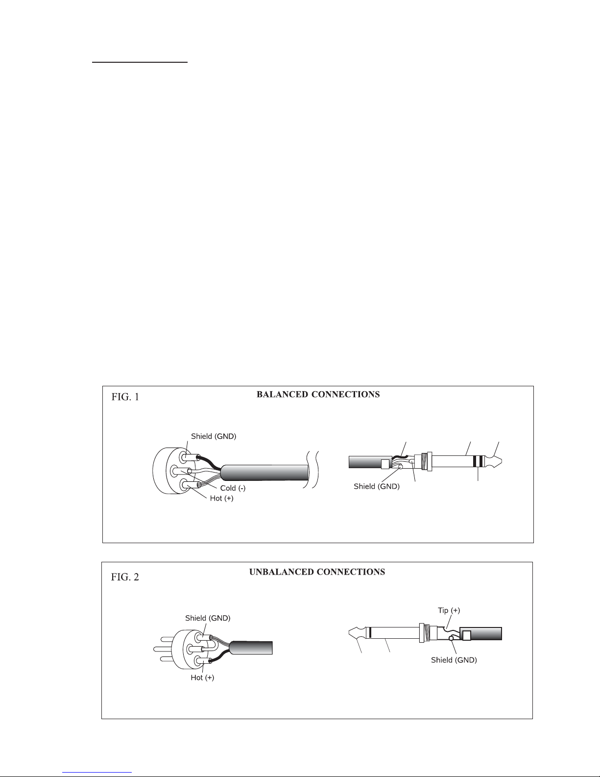
Each channel is provided with one XLR mic input and one ¼” TRS jack line input. Both mic and line
sockets should not be used simultaneously.
MIC 3 pin XLR input
For balanced, low impedance microphones, wire pin 1 to screen/ground/earth, pin 2 to
positive/hot/+ve phase, and pin 3 to negative/cold/-ve phase.
For unbalanced microphones, wire pin 1 to ground, pin 2 to signal, and pin 3 to pin 1.
48V phantom power may be applied to the microphone by selecting the appropriate switch on the rear
panel.
Do not connect 48V phantom power to unbalanced microphones.
LINE ¼” TRS Jack for use with balanced, line level input signals
Wire Tip to positive/hot/+ve phase, Ring to negative/cold/-ve phase and Sleeve to ground.
For unbalanced microphones, use a TS jack and wire Tip to signal and Sleeve to ground
The line input is electronically balanced but may also be used with unbalanced signals simply by
plugging in an unbalanced TS jack.
Mono Jack
6.3 1/4’’mm
XLR CONNECTOR
3
Tip
(+)
Sleeve
(GND)
1
2
Stereo Jack
6.3 mm 1/4’’
1
3
2
XLR CONNECTOR
Sleeve
(GND)
RING (-)TIP (+)
RING (-)
TIP (+)
2
Page 5
POWER
ON
O
I
LEVEL
OUTPUT
LEVEL
+6
+3
0
-3
-6
-10
-20
SIGNAL
CLIP
SIGNAL
CLIP
SIGNAL
CLIP
SIGNAL
CLIP
LEVEL LEVEL LEVEL LEVEL
ACTIVE ACTIVE ACTIVE ACTIVE LOCKOUT
FIXED
PRIORITY
MASTER
ON
OFF
LOUD LOUD LOUD LOUD
NORM. NORM. NORM. NORM.
SOFT SOFT SOFT SOFT
VOX
BYPASS
VOX
BYPASS
VOX
BYPASS
VOX
BYPASS
12
3
4
THRESHOLD
SELECTED CHANNEL
14 2 5
3 9
6 7 8
10 11
Auto 4
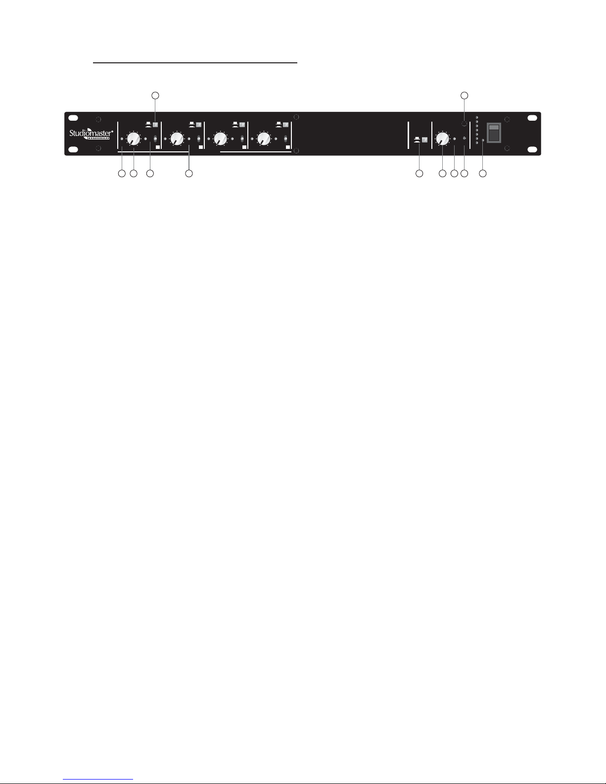
FRONT PANEL CONTROLS AND INDICATORS
1) LEVEL
2) LOUD/NORMAL/SOFT Channel threshold selection
3) VOX/BYPASS Threshold bypass for background music, VOX for voice operation
4) SIGNAL/CLIP Bicolor LED lights green at -20dBu, and red for clip at 0dBu
5) ACTIVE Green LED indicates that the channel is active
6) FIXED PRIORITY When selected, channel priority is in the following fixed order:
Channel 1 has priority over channels 2, 3 and 4
Channel 2 has priority over channels 3 and 4
Channel 3 has priority over channel 4
7) MASTER THRESHOLD
Threshold control is the level which activates the channel. If the channel signal exceeds the
threshold, the channel is activated depending on the priority settings.
8) LOCKOUT
9) MASTER LEVEL
10) OUTPUT LEVEL
11) POWER Power on/off switch with LED indication
Channel level control
Common threshold control for all four channels
LED indicated that a high priority channel is active
Recessed control to adjust output level
LED bar graph indicates output level
3
Page 6

LINK OUT
INSERT
LINK IN
OUTPUT
MIC
MIC
MIC
MIC
PHANTOM
PHANTOM
PHANTOM
PHANTOM
PRIORITY
PRIORITY
PRIORITY
PRIORITY
ATTEN.
ATTEN.
ATTEN.
20dB
20dB
20dB
20dB
INPUT 4 INPUT 3 INPUT 2 INPUT 1
4
3
2
1
G
CONTROLVOLTAGE OUT
EXT. DC
24V
USE ONLY
RECOMMENDED PSU
12 13
14
1517 16
1819
21
20
22
OFF
ON
OFF
ON
LIMITER
LAST MIC
ATTEN.
12dB
LINE
12dB
LINE
12dB
LINE
12dB
LINE
REAR PANEL CHANNEL CONTROLS
A 4-position DIP switch is provided on the rear panel for each input channel. These switches are:
12) PRIORITY Set high priority (up) or low priority (down)
13) MIC/LINE Set Mic input (up) or Line input (down)
14) PHANTOM Set Phantom supply (48V) for Mic input (up). It is internally disabled for Line
15) ATTEN. 12dB/20dB Set attenuation of inactive channel : 20dB (up) or 12dB (down)
REAR PANEL COMMON CONTROLS
A 2-position DIP switch controls the output. These switches are:
16) LIMITER Set Limiter On (up) or Off (down).
17) LAST MIC Set Last Mic On (up) or Off (down)
The internal limiter restricts the output if it exceeds a threshold which is set to about 0dBu. This is
designed to minimize signal clipping if the output signal is too large.
Normally, when a microphone is inactive, it is mu
ted. During a live discussion, every inactive microphone
is followed by another microphone which is active. At the end of the discussion, when all microphones
are inactive, there is no output from the Auto 4 mixer, as if the entire system has “gone dead”.
To prevent this, the Last Mic option can be enabled. In that case, the last microphone is not muted,
giving the effect that the microphone is not being used but “not gone dead”. Output from the amplifier
would then be the ambient background sound.
18) CONTROL VOLTAGE OUT CMOS compatible logic signals, active high (5V)
Whenever any microphone is active, a corresponding control output is available on the rear panel.
This can be used for a variety of applications such as activating a camera, disabling overhead speaker,
etc.
19) EXT. DC 24V The Auto 4 Mixer can be operated on external 24V dc supply.
Please note that the negative terminal of this 24V supply should not be connected to signal ground.
20) INSERT ¼” TRS insert jack for connection to external signal processing units.
Wire Tip to Send, Ring to Return and Sleeve to Ground.
4
Page 7

21) LINK IN & LINK OUT RJ45 connectors for linking several Auto 4 mixers.
Use a CAT 5 cable to connect Link Out of one Auto 4 mixer to Link In of the next mixer. When several
Auto 4 mixers are linked in this way, output of the last mixer should be connected to the amplifier.
22) DC Input Connector
Connector to power supply unit. Use the power supply which has been supplied with the mixer.
5
Page 8

SET UP PROCEDURE
= Connect Microphone to input 1 XLR
= Select rear panel switches to set Low Priority, Mic mode, Phantom off, Attenuation 20dB
= Set VOX/ Bypass switch to Bypass
= Connect output XLR to input of amplifier
= the power to the Auto 4Switch on
= Switch on the amplifier
= Speak normally into the microphone
= Set Channel Level until the Signal/Clip Led lights occasionally
= Set Master level (screw-driver adjustment) as required
= Set VOX/Bypass switch to VOX
=
Set channel threshold to normal
= If required, set to Loud or Soft, depending on the speaker
= Set Master Threshold to minimum
= Increase Master Threshold so that background sound does not turn on the channel
= Speak normally into the microphone
= If required decrease Master Threshold so that sound does not break at the beginning of a word
= Repeat above procedure for all other channels
6
Page 9
APPLICATION NOTE
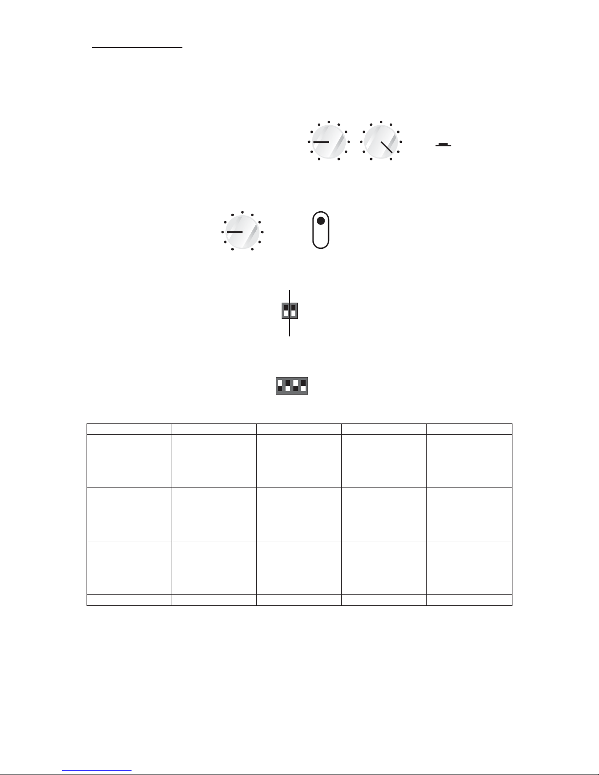
OPERATION OF SINGLE AUTO 4 MIXER
Fixed Priority Mode
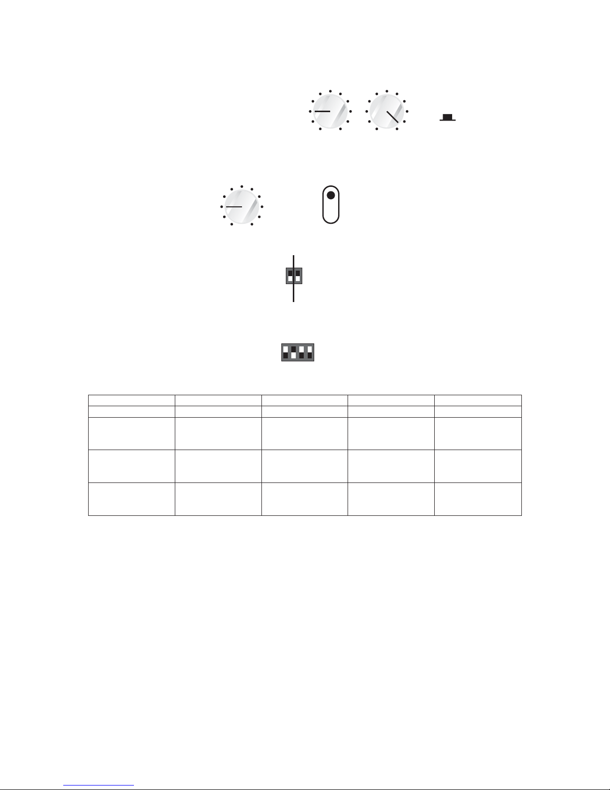
Front Panel Settings
Common Settings:
Master Threshold: 9 o’clock position
Fixed Priority: on (pressed)
Master Level: Maximum
Settings for each channel:
Level: (or, according to microphone requirement)9 o’clock position
Threshold: Normal
Rear Panel Settings
Common Settings:
Last Mic: Off
Limiter: Off
Settings for each channel:
Priority Switch: Low
Mic/Line Switch: Mic
Phantom Switch: Low
Atten. Switch: 20dB
Channel 1 Channel 2 Channel 3 Channel 4 Output
On On or Off On or Off On or Off Output from Ch. 1
– other channels
attenuated by
20dB and mixed
with Ch.1
Off On On or Off On or Off
– other channels
attenuated by
20dB and mixed
with Ch.2
Off Off On On or Off
– channel 4
attenuated by
20dB and mixed
with Ch.3
In this mode:
Channel 1 has priority over channels 2, 3, and 4
Channel 2 has priority over channels 3 and 4
Channel 3 has priority over channel 4
All non-priority channels are attenuated and mixed with the priority channel.
Off Off Off On Output from Ch. 4
ON
FIXED PRIORITYMASTER
THRESHOLD
OFF
ON
OFF
ON
LIMITER
LAST MIC
7
MASTER
LEVEL
MIC
PHANTOM
PRIORITY
ATTEN.
20dB
12dB
LINE
LEVEL
THRESHOLD
LOUD
NORM.
SOFT
Output from Ch. 2
Output from Ch. 3
Page 10

THRESHOLD
LOUD
NORM.
SOFT
Auto Mode - All Low-Priority Channels
Front Panel Settings
Common Settings:
Master Threshold: 9 o’clock position
Master Level: Maximum
Fixed Priority: Off (released)
Settings for each channel:
Level: (or, according to microphone requirement)9 o’clock position
Threshold: Normal
Rear Panel Settings
Common Settings:
Last Mic: Off
Limiter: Off
Settings for each channel:
Priority Switch: Low
Mic/Line Switch: Mic
Phantom Switch: Low
Atten. Switch: 20dB
On Off Off Off
On Becomes On but
inactive while
Channel 1 is
active
Off Off Channel 1 added
with 20dB
attenuated
Channel 2
while Channel 1 is
active
Off On
inactive while
Channel 2 is
active
with 20dB
attenuated
Channel 3
In this mode:
Only one channel is active at any time.
All other channels are inactive.
Inactive channels are attenuated by 20dB and mixed with the active channel.
Channel 1 Channel 2 Channel 3 Channel 4 Output
Off Becomes On Off Off Channel 2
Becomes On but Off Channel 2 added
Channel 1
8
MASTER
THRESHOLD
MASTER
LEVEL
OFF
FIXED PRIORITY
LEVEL
OFF
ON
OFF
ON
LIMITER
LAST MIC
MIC
PHANTOM
PRIORITY
ATTEN.
20dB
12dB
LINE
Page 11
MIC
PHANTOM
PRIORITY
ATTEN.
20dB
12dB
LINE
MIC
PHANTOM
PRIORITY
ATTEN.
20dB
12dB
LINE
MIC
PHANTOM
PRIORITY
ATTEN.
20dB
12dB
LINE
MIC
PHANTOM
PRIORITY
ATTEN.
20dB
12dB
LINE
THRESHOLD
LOUD
NORM.
SOFT
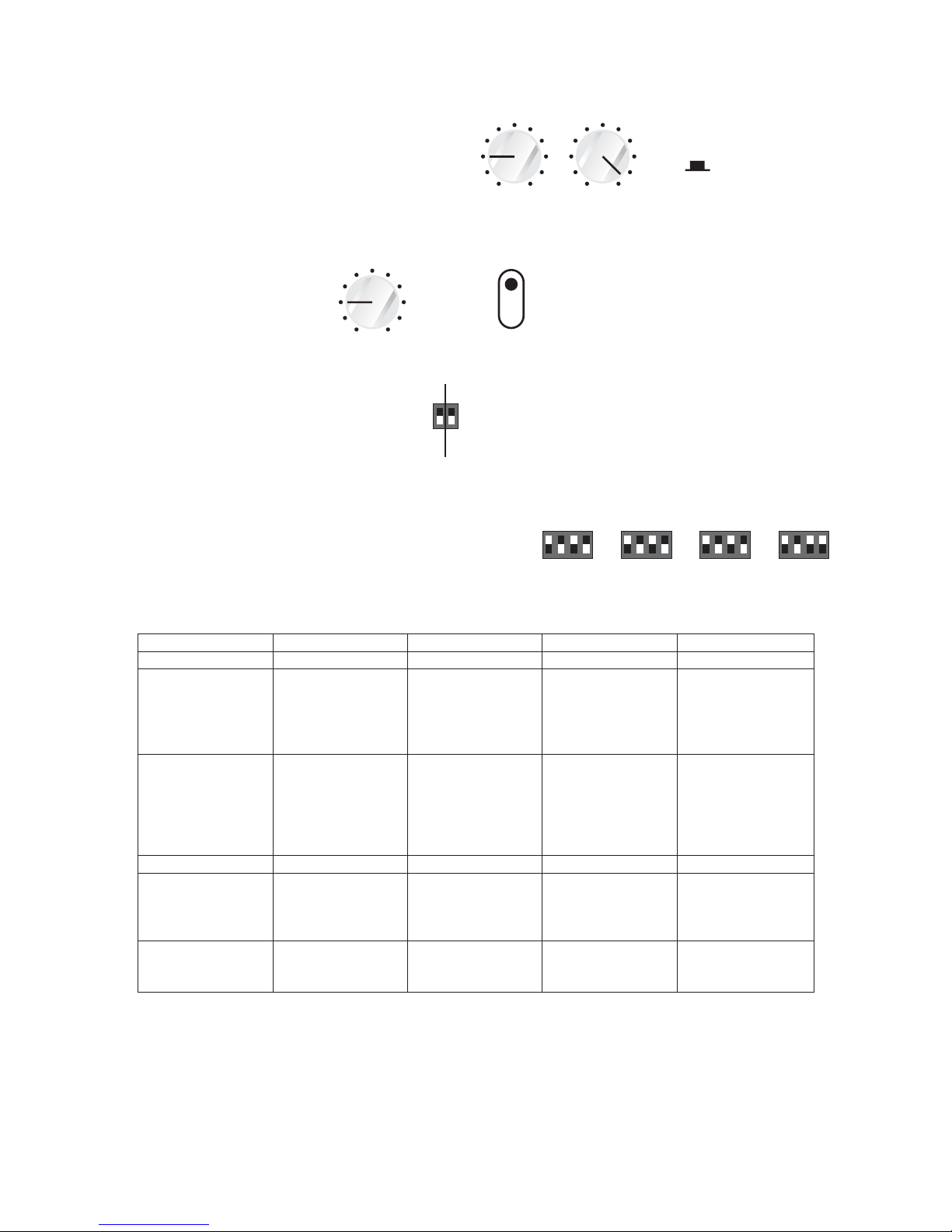
Auto Mode - Only one High-Priority Channel
Front Panel Settings
Common Settings:
Master Threshold: 9 o’clock position
Master Level: Maximum
Fixed Priority: Off (released)
Settings for each channel:
Level: (or, according to microphone requirement)9 o’clock position
Threshold: Normal
Rear Panel Settings
Common Settings:
Last Mic: Off
Limiter: Off
Settings for each channel:
Priority Switch: Low (Channels 2, 3 and 4)
Priority Switch: High (Channel 1)
Mic/Line Switch: Mic
Phantom Switch: Low
Atten. Switch: 20dB
Off On Off Off
Becomes On
while Channel 2 is
active
On Off Off
becomes active
immediately and
mutes channel 2
(20dB attenuation)
On
while Channel 1 is
active
active and
remains active –
channel 2 is
attenuated by
20dB
Off Off On Off
Off Off On Becomes on but
inactive while
Channel 3 is
active
Channel 3 added
with 20dB
attenuated
Channel 4
Off Off Off
while Channel 3 is
active
Channel 4
In this mode:
High-priority channel can interrupt any low-priority channel.
A low-priority channel can become active only when the high-priority channel becomes inactive.
Inactive channels are attenuated by 20dB and mixed with the active channel.
Channel 1 Channel 2 Channel 3 Channel 4 Output
Channel 2
Channel 1
Channel 3
Becomes On Off Off Channel 1 is
Becomes On
9
MASTER
THRESHOLD
MASTER
LEVEL
OFF
FIXED PRIORITY
LEVEL
OFF
ON
OFF
ON
LIMITER
LAST MIC
Channel 4
Channel 3
Channel 2 Channel 1
Page 12
MIC
PHANTOM
PRIORITY
ATTEN.
20dB
12dB
LINE
THRESHOLD
LOUD
NORM.
SOFT
Auto Mode - All High-Priority Channels
Front Panel Settings
Threshold: Normal
Rear Panel Settings
Common Settings:
Last Mic: Off
Limiter: Off
Settings for each channel:
Priority Switch: High
Mic/Line Switch: Mic
Phantom Switch: Low
Atten. Switch: 20dB
On Off Off Off
On On Off Off
mixed, gain
reduced by 3dB
On On On Off 2
3 mixed, gain
reduced by 3dB
On On On On
mixed, gain
reduced by 6dB
In this mode:
All high-priority channels can be active at the same time.
If two or three channels are active, the output is reduced by 3dB.
If all four channels are active, the output is reduced by 6dB.
Fixed Priority: Off (released)
Common Settings:
Master Threshold: 9 o’clock position
Master Level: Maximum
Settings for each channel:
Level: (or, according to microphone requirement)9 o’clock position
Channel 1 Channel 2 Channel 3 Channel 4 Output
Channel 1
Channel 1 and 2
Channel 1, 2 and
All Channels
10
MASTER
THRESHOLD
MASTER
LEVEL
OFF
FIXED PRIORITY
LEVEL
OFF
ON
OFF
ON
LIMITER
LAST MIC
Page 13

CASCADED OPERATION OF MULTIPLE AUTO 4 MIXERS
Auto 4 Mixer 1 Auto 4 Mixer 2 Auto 4 Mixer 3 System operates as Active channels
Auto mode
Low priority on
all channels
Auto mode
Low priority on
all channels
Auto mode
Low priority on
all channels
12-channel Auto 4
Mixer
Only one channel at any time
Auto mode
Low priority on
all channels
Auto mode
High priority
channels 5 & 8
Low priority
channels 6 & 7
Auto mode
Low priority on
all channels
12-channel Auto 4
Mixer
Channels 5 & 8 can interrupt
any other channels.
If channels 5 & 8 are active
at the same time, output is
attenuated by 3dB
Auto mode
Low priority on
all channels
Auto mode
High priority
channel 5
Low priority
channels 6, 7 &
8
Auto mode
High priority
channel 10
Low priority
channels 9, 11
&12
12-channel Auto 4
Mixer
Channels 5 & 10 can
interrupt any other channels.
If channels 5 & 10 are active
at the same time, both are
available at output without
attenuation
Auto mode
Low priority on
all channels
Manual mode
Priority
sequence:
Channel 5 has
priority over 6, 7
and 8;
Channel 6 has
priority over 7 &
8;
Channel 7 has
priority over 8
Auto mode
High priority
channel 10
Low priority
channels 9, 11
&12
8-channel Auto 4
Mixer with channels 1
to4and9to12.
Channel 10 can interrupt any
of the channels (1 to 4, 9, 11,
or 12).
Output of Auto 4 Mixer 2 is
mixed with the final output
Auto 4 Mixer 1
Channels 1 to 4
Auto 4 Mixer 2
Channels 5 to 8
Auto 4 Mixer 3
Channels 9 to 12
Link In Link InLink OutLink Out
To Amplifier
11
Page 14
12
Control of External Lamps or Cameras
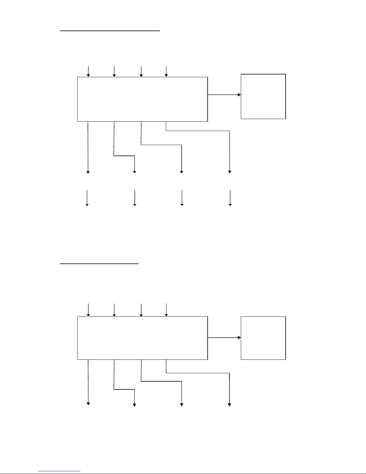
Whenever a mic is active, a corresponding control voltage is available from the rear panel. This can be
used to switch on overhead lamp or camera as shown below:
During a discussion, there could be frequent changes between different microphones. But, frequent
changes of lamp / camera may not be desirable. The delay circuits should ignore short interruptions by
any speaker and enable the lamp / camera of the main microphone.
Ch. 1 Ch. 2 Ch. 3
Ch. 4
Inputs from microphones
1234
Control Outputs
Delay
circuit
Delay
circuit
Delay
circuit
Delay
circuit
Switch lamp
/ camera 1
Switch lamp
/ camera 2
Switch lamp
/ camera 3
Switch lamp
/ camera 4
Auto 4 Mixer
Amplifier
Control of Overhead Speakers
Whenever a microphone is active, a corresponding control voltage can be used to switch off overhead
speaker. This prevents feedback from the microphone into its own speaker. This application is shown
below:
During a discussion, there could be frequent changes between different microphones. In order to avoid
feedback, the overhead speaker should be switched off as soon as any microphone becomes active.
Auto 4 Mixer
Ch. 1 Ch. 2 Ch. 3
Ch. 4
Inputs from microphones
1 2 3 4
Control Outputs
Switch off
Speaker 1
Switch off
Speaker 2
Switch off
Speaker 3
Switch off
Speaker 4
Auto 4 Mixer Amplifier
Page 15

Output Impedance 200 ohms≤
TECHNICAL SPECIFICATIONS
Input Impedance
Maximum Input Level
Maximum Output Level*
Mic 4,000 ohms
≥
Line 30,000 ohms≥
Mic - 30 dBu
Line + 20 dBu
Line +14 dBu
Maximum Gain ≥ 70 dB
Inactive Channel Attenuation 12dB or 20dB switch-selectable
Frequency Response 60 Hz to 30 kHz at - 3dB points
Dynamic Range** 75 dB ± 10 dB, dependent upon gain control settings
Equivalent Input Noise –120 dBu (150 ohms) at maximum gain
Switch-selectable Options Limiter (above 0dBu), Last Mic On
Microphone Phantom +48V DC
Control Voltage Out +5V DC
Power Requirement 230V AC, 100 mA, max. for external SMPS
Operating Temperature 0° to 40° C
* Master Level control set at maximum (fully clockwise).
** Input terminated with 150 ohms, A-weighted using Audio Precision System.
+24V DC, 250mA max. for external DC supply
Dimensions 482.6 mm W x 135 mm x 44 mm H
Weight 2.2 Kg
Included Accessories SMPS with connectors, Link Cable
13
Page 16

LITMA5M8 REV.0
PRODUCT OF AUDIOPLUS
A1/A2, Giriraj Industrial Estate,
Mahakali Caves Road, Andheri (East),
Mumbai-400 093. India
Tel.: +91-22-66916232 / 33, 30880743,
30880776, 26870268 Fax: 26871453
Email: [email protected]
Studiomaster professional reserves the right to make modifications to its
products without notice
 Loading...