

Page 1
USER
GUIDE
+5
-5
-10
-20
-30 -30
8
0
+5
-5
-10
-20
8
0
0
-5
-20
-30
+5
0
-5
-20
-30
+5
0
-5
-20
-30
+5
0
-5
-20
-30
+5
0
-5
-20
-30
+5
0
-5
-20
-30
+5
+10
-10
8
+10
-10
8
+10
-10
8
+10
-10
8
+10
-10
8
+10
-10
8
0 10
0 10
0 10
PHONES
PLAYBACK
LEVEL
RECORD
LEVEL
+48V
POWER
POWER
0 10
DSP
0 10
MON
DSP TO
LEVEL
ON
0 10 0 10
AUX
INPUT
AUX/DSP
SEND
MON
SEND
0 10
LR
+15
12
9
6
3
0dB
3
6
9
12
15
-20
MAIN MIX / PFL
16 CHANNEL
28 INPUT
CUSTOM DSP
MIC
PFL PFL PFL PFL
PEAK PEAK PEAK PEAK
40
20
12 50dB
40
20
12 50dB
0 10
0 10
LR
BAL
0 10
0 10
LR
-
+
LO
45Hz
-
+
LO
45Hz
-
+
HI
12K
-
+
HI
12K
BAL
0 10
0 10
LR
BAL
0 10
0 10
LR
BAL
GAIN
MIC
GAIN
LINE LEVEL
+4
-10
LINE LEVEL
+4
-10
REV
30 30
MON MON
AUX/
DSP
MON
AUX/
DSP
MON
40
20
12 50dB
40
20
12 50dB
-
+
LO
45Hz
-
+
LO
45Hz
-
+
HI
12K
-
+
HI
12K
MIC
GAIN
MIC
GAIN
LINE LEVEL
+4
-10
LINE LEVEL
+4
-10
30 30
AUX/
DSP
AUX/
DSP
1K
1K5600
3K350
1K
1K5600
3K350
PFL PFL
PEAK PEAK
0
40
20
GAIN
-
+
12 60dB
HI
12K
40
20
GAIN
-
+
12 60dB
HI
12K
-
+
0 10
0 10
LR
LO
60Hz
PAN
-
+
0 10
0 10
LR
LO
60Hz
PAN
-
+
MID
-
+
MID
250Hz 6KHz 250Hz 6KHz
30 30
AUX/
DSP
MON
AUX/
DSP
MON
BPX
162
16 L R
DSP
MAIN
MIX
TRIPLE
INPUT
15
TRIPLE
INPUT
14
TRIPLE
INPUT
13
TRIPLE
INPUT
1211
VOCAL1
VOCAL2
VOCAL3
ADT
REV1
REV2
DELAY
1
2
3
4
5
6
16 CHANNEL
28 INPUT
CUSTOM DSP
162
BPX
Page 2

6
2
1 Introduction
1 Read the User Guide
1 Unpacking
1 Safety Instructions
2 Controls & Features - Mono channels 1-12
3 Controls & Features - Mono/Stereo channels 13-16
4 Controls & Features - Output / DSP Section
5 Controls & Features - Rear Panel Output Section
6 Controls & Features - Rear panel Input Section
7 Trouble Shooting
7 Internal Options
8 Wiring Connections
9 Technical Specification
10 Warranty
11 Service Information
INDEX
INDEX
www.studiomaster.com
www.studiomaster.com
162
BPX
Page 3

1
INTRODUCTION
Thank you for buying this Studiomaster product.
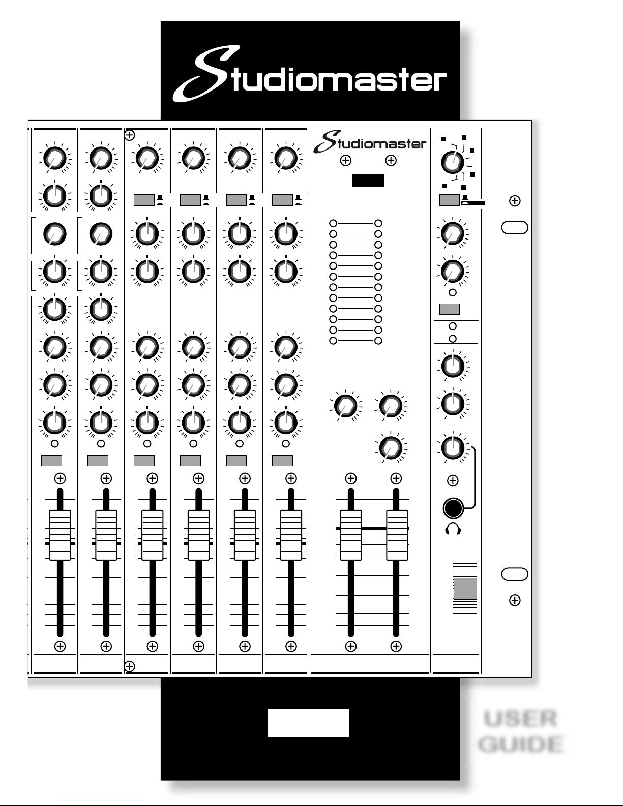
The 162BPX is a 16 channel, 28 input compact audio
mixer designed specifically for the requirements of the
working sound engineer.
The 162BPX features ultra quiet mic preamps, renowned
Studiomaster EQ and ease of use, all housed in a stylish
6U rack mountable package.
The 162BPX also features Studiomaster's custom
designed DSP providing ultra clean reverbs and delay
effects to enhance the vocal performance.
READ THE USER GUIDE
Despite the sophisticated design the 162BPX is very easy
to use although to get the best from your new purchase,
we recommend you read this User Guide before getting
down to any serious work.
It also contains important safety information as well as
practical hints.
UNPACKING
Remove your Studiomaster product from its packing and
ensure that along with this User Guide you have an A.C.
power cord / mains lead and a warranty card.
Retain the packing carton in the eventuality that the unit
needs to be returned for service or repair, and please
complete and return your warranty card. Returning the
completed warranty card does not diminish your statuary
rights in any way.
SAFETY INSTRUCTIONS
1. Before connecting the A.C. power cord make
sure the Voltage selector (located on the rear
panel) is set to your local supply voltage.
See Voltage selector on Page 6.
2. Only use the A.C. power cord / mains lead
supplied with the product. Replace if it becomes
damaged in any way.
3. Never operate without, or remove the safety
ground (earth) from the A.C. power cord / mains
lead.
4. Do not attempt to remove screws or panels on
your 162BPX audio mixer. There are no user
serviceable parts inside.
5. Do not operate the unit next to heat sources such
as radiators.
6. The unit should not be operated or stored near
rain or moisture.
7. This equipment must not be exposed to dripping
or splashing and no objects filled with liquids
should be placed on top of it.
8. Write the serial number in the box provided in the
Warranty section for future reference.
9. If the unit gets damaged, has been dropped or
appears to have developed a fault refer to the
Service Information section for details.
WARNING
THIS APPARATUS MUST BE EARTHED (GROUNDED)
EXPECT THE BEST
EXPECT THE BEST
6
2
162
BPX
Page 4
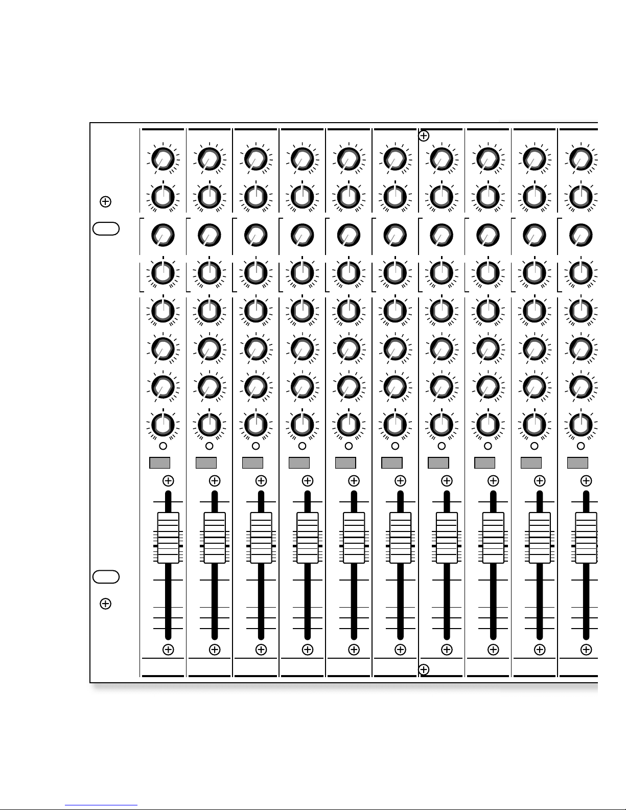
Controls & Features - Mono Channels 1-12
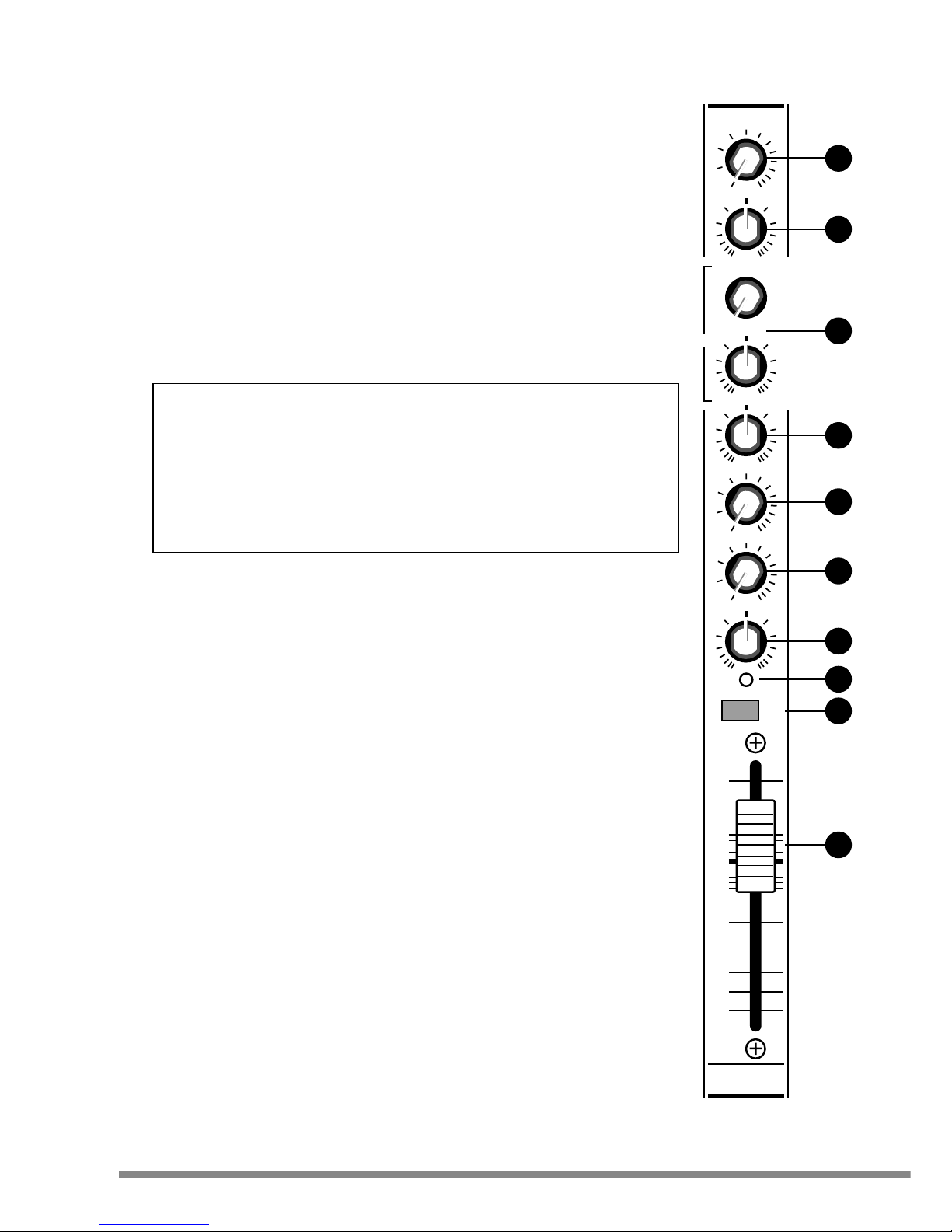
1 GAIN : The Gain control is used to match the incoming signal level to the internal operating
level of the 162BPX. This ensures the best performance, reduces noise and avoids
distortion. The Mic Gain range is 12 to 60dB
2 HI : The HI control cuts or boosts the high frequency (or treble) element of the sound. In the
centre (12 o'clock) position, the sound is unaffected. The HI control works at 12kHz.
3 MID : The MID consists of two controls. The lower control operates in the same way as the
HI & LO. The upper control (the 'sweep') adjusts the frequency at which it operates. The
MID frequency sweep control adjusts between 250Hz and 6kHz.
4 LO : The LO control operates in the same way as the HI control except that it affects the
low frequency (bass) part of the sound. The LO control operates at 60Hz.
Tone controls : HI, MID & LO
The controls marked HI, MID and LO are very useful for changing the characteristics or tone of the sound. For simplicity or
for new users set these controls to the centre position, which effectively turns off or bypasses the tone control section and
you will not need to worry about these controls until you feel more confident.
However to get the best out of your audio system or if you just want to experiment read on....
Adding a little HI on CDs can add brightness to the sound. For microphones increasing the MID ranges tends to 'lift' the
vocal adding clarity to the voice.
For CDs, adding LO makes the bass section of music more prominent. For microphones doing the opposite and removing a
little bass helps stop the 'popping' or 'boomy' sound often apparent when a microphone is used too close to the mouth.
For best results with microphones or CDs, don't be over enthusiastic with the tone controls as this can make the sound unnatural. With guitars or other instruments more extreme tone setting can be used to create more of a sound effect.
5 AUX/DSP : The AUX/DSP control is assigned post - fader and used to send the sound in
the channel to the internal DSP (digital signal processor). The sound is also sent to the
AUX SEND output for use with external effects processors.
6 MON : The MON control can be used when an additional or different mix of sound is
required (such as using stage monitor speakers or multiple headphones for the musicians).
As the MON control is turned clockwise more of the sound in the channel is routed, via the
MON SEND control (24), to the MON SEND output on the rear panel. This would then be
connected to an amplifier to power the stage monitor speakers or headphone system.
Mon and AUX controls are very similar except that adjusting the channel fader does not
affect the sound at the MON SEND. Musicians listening to the sound from the MON SEND
do not want it changing when a channel fader is adjusted. The opposite is required when
an effects loop is used, the effect needs to change with the position of the channel fader.
This keeps the blend of original and treated signal constant.
7 PAN : Adjusts the position of the channel signal between left or right output channel.
8 PEAK : The Peak LED indicates that the channel signal is approaching its maximum level.
If the Peak LED remains lit, reduce the channel GAIN (1) control setting until the LED
flashes only on signal peaks.
9 PFL : Depressing the PFL (pre fade listen) button allows the selected channel (or
channels) to be monitored via the headphone output. When the PFL button is activated the
Peak LED stays fully illuminated and the level is also shown on the Main Mix bargraph
meters.
10 FADER : The fader adjusts the level from the channel to the main output. The fader acts as
a volume control for each channel. they join all the various sounds together creating a
blend or 'mix' of sounds. The long, smooth faders make small adjustments easy as well as
giving a visual representation of sound levels. In use, aim to set the fader at the 0dB
position. It can then be raised or lowered to adjust the sound (mix).
WHAT HAPPENS IF I PRESS THIS?
CONTROLS & FEATURES
2
www.studiomaster.com
www.studiomaster.com
+10
0
-5
-10
-20
-30
8
+5
40
30
20
-
+
-
+
1K
1K5600
3K350
-
+
0 10
0 10
LR
LO
60Hz
AUX/
DSP
MON
PAN
12 60dB
MID
PFL
PEAK
HI
12K
GAIN
250Hz 6KHz
1
1
2
3
4
5
6
7
8
9
10
Page 5
WHAT HAPPENS IF I PRESS THIS?
CONTROLS & FEATURES
3
EXPECT THE BEST
EXPECT THE BEST
Controls & Features - Mono/Stereo Channels 13-16
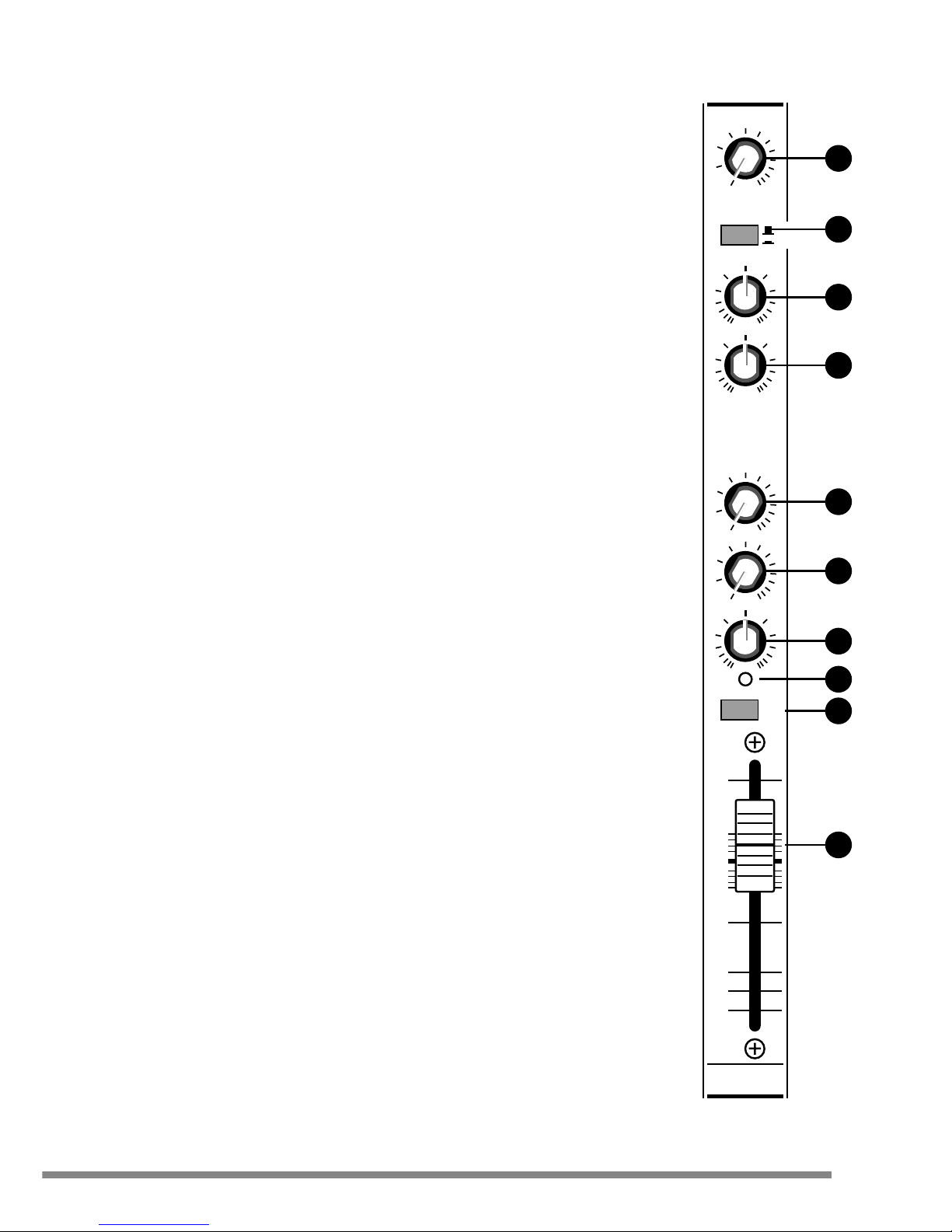
11 MIC GAIN : Sets the level of the incoming mic signal. The mic gain range is 12 to 50dB.
12 LINE LEVEL : This sets the level of the incoming stereo line signal. In the out (or up)
position the gain structure is optimised for +4dB operation. The in (or down) position
matches the input channel to signal levels of -10dBV.
The Gain control ( or LEVEL switch) allows the signal coming into the 162BPX to be
matched (as close as possible) to the internal operating level helping to preserve the 'signal
to noise ratio' throughout the 162BPX. The line level switch will also increase the gain of
the mic signal. This can be useful if the mic gain at maximum is not enough in certain
situations.
13 HI : The HI control cuts or boosts the high frequency (or treble) element of the sound. In the
centre (12 o'clock) position, the sound is unaffected. The HI control works at 12kHz.
14 LO : The LO control operates in the same way as the HI control except that it affects the
low frequency (bass) part of the sound. The LO control operates at 45Hz.
15 AUX/DSP : The AUX/DSP control is assigned post - fader and used to send the sound in
the channel to the internal DSP (digital signal processor). The sound is also sent to the
AUX SEND output for use with external effects processors.
16 MON : The MON control can be used when an additional or different mix of sound is
required (such as using stage monitor speakers or multiple headphones for the musicians).
As the MON control is turned clockwise more of the sound in the channel is routed, via the
MON SEND control (24), to the MON SEND output on the rear panel. This would then be
connected to an amplifier to power the stage monitor speakers or headphone system.
Mon and AUX controls are very similar except that adjusting the channel fader does not
affect the sound at the MON SEND. Musicians listening to the sound from the MON SEND
do not want it changing when a channel fader is adjusted. The opposite is required when
an effects loop is used, the effect needs to change with the position of the channel fader.
This keeps the blend of original and treated signal constant.
17 BAL : BALANCE - Sets the Left / Right balance of the stereo line signals or pans the mic
signal.
18 PEAK : The Peak LED indicates that the channel signal is approaching its maximum level.
If the Peak LED remains lit, reduce the channel GAIN control setting until the LED
flashes only on signal peaks.
Note : On stereo line channels the input level is adjusted using the level switch. If the peak
LED remains lit, it may be necessary to reduce the output volume of the equipment
connected to the channel.
19 PFL : Depressing the PFL (pre fade listen) button allows the selected channel (or
channels) to be monitored via the headphone output. When the PFL button is activated the
Peak LED stays fully illuminated and the level is also shown on the Main Mix bargraph
meters.
20 FADER : The fader adjusts the level from the channel to the main output. The fader acts as
a volume control for each channel. they join all the various sounds together creating a
blend or 'mix' of sounds. The long, smooth faders make small adjustments easy as well as
giving a visual representation of sound levels. In use, aim to set the fader at the 0dB
position. It can then be raised or lowered to adjust the sound (mix).
11
12
13
14
15
16
17
18
19
20
0
-5
-20
-30
+5
+10
-10
8
PFL
PEAK
0 10
0 10
L
R
BAL
MON
40
20
12 50dB
-
+
LO
45Hz
-
+
HI
12K
MIC
GAIN
LINE LEVEL
+4
-10
30
AUX/
DSP
13
TRIPLE
INPUT
Page 6
DSP PROGRAMS
Reverb effects Delay programs
VOCAL1 Delay + medium 3sec reverb 1 120mS
VOCAL2 Delay + short 2sec reverb 2 240mS
VOCAL3 Delay + long 4sec reverb 3 360mS
ADT Short delay + ambient reverb 4 480mS
REV1 Warm reverb 5 600mS
REV2 Plate reverb 6 720mS
Controls & Features - Output / DSP Section
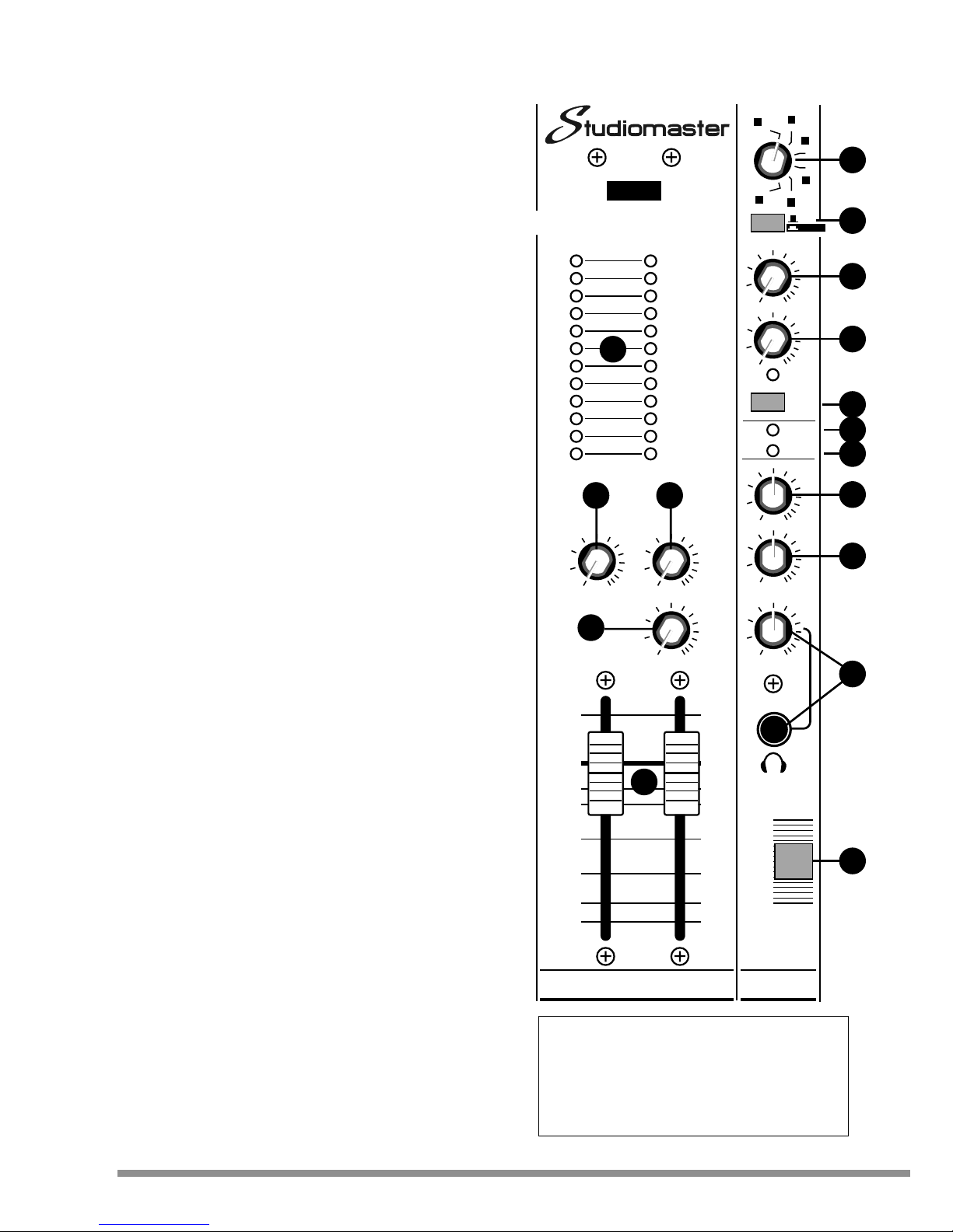
21 METERS : The meters have a PPM characteristic and normally
monitor the Left and Right stereo mix.
When one or more PFL buttons are depressed, the meters
automatically switch to monitoring the PFL buss.
22 AUX INPUT : Controls the level of signals sent to the MAIN MIX
output from stereo aux input connectors (44).
23 AUX/DSP SEND : Controls the overall signal level sent from
each channel to the internal DSP and AUX SEND OUTPUT.
24 MON SEND : Controls the overall signal level sent from each
channel to the MON SEND OUTPUT.
25 LEFT & RIGHT FADERS : These faders control the level of the
main mix to the left and right outputs (40).
26 DSP PROGRAM : The rotary program switch selects any of 6
Reverb effects or 6 delay programs.
27 DSP BANK SWITCH : This switch selects either reverb or delay
effects when choosing your effect from the rotary program switch.
28 DSP TO MON : Routes the sound from the DSP to the MON
SEND control / output.
29 DSP LEVEL : Controls the amount of sound from the DSP sent
to the main mix. The sound then mixes with the original
untreated sound giving the required effect.
30 DSP ON/OFF : Turns on and off the selected DSP program.
31 POWER LED : The Power LED indicates the 162BPX is
switched on.
32 +48V LED : Indicates that +48V phantom power is available to
microphone channels (see rear panel switch 39).
33 RECORD LEVEL : Controls the level to the RECORD Left/Right
RCA phono sockets on the rear panel (37).
34 PLAYBACK LEVEL : Controls the level from the PLAYBACK
Left/Right RCA phono sockets on the rear panel (38).
35 PHONES : Controls the headphone output level. The
headphones monitor the MAIN MIX or PFL signal (if more than
one PFL buttons are depressed).
The Phones jack will accept stereo headphones with a 1/4" stereo
TRS jack. Wired Tip=Left, Ring=Right, Sleeve=Ground.
The best headphones to use with the 162BPX are studio grade
150-400ohm types, although most types can be used but may
not sound as loud.
WARNING : Care should be taken when using headphones as
prolonged excessive volume can damage hearing.
36 POWER : Turns the 162BPX On or OFF.
WHAT HAPPENS IF I PRESS THIS?
CONTROLS & FEATURES
4
www.studiomaster.com
26
27
28
29
30
31
32
33
34
35
36
+5
-5
-10
-20
-30 -30
8
0
+5
-5
-10
-20
8
0
0 10
0 10
0 10
PHONES
PLAYBACK
LEVEL
RECORD
LEVEL
+48V
POWER
POWER
0 10
DSP
0 10
MON
DSP TO
LEVEL
ON
0 10 0 10
AUX
INPUT
AUX/DSP
SEND
MON
SEND
0 10
LR
+15
12
9
6
3
0dB
3
6
9
12
15
-20
MAIN MIX / PFL
16 CHANNEL
28 INPUT
CUSTOM DSP
REV
BPX
162
LR
DSP
MAIN
MIX
VOCAL1
VOCAL2
VOCAL3
ADT
REV1
REV2
DELAY
1
2
3
4
5
6
21
25
22 23
24
Page 7
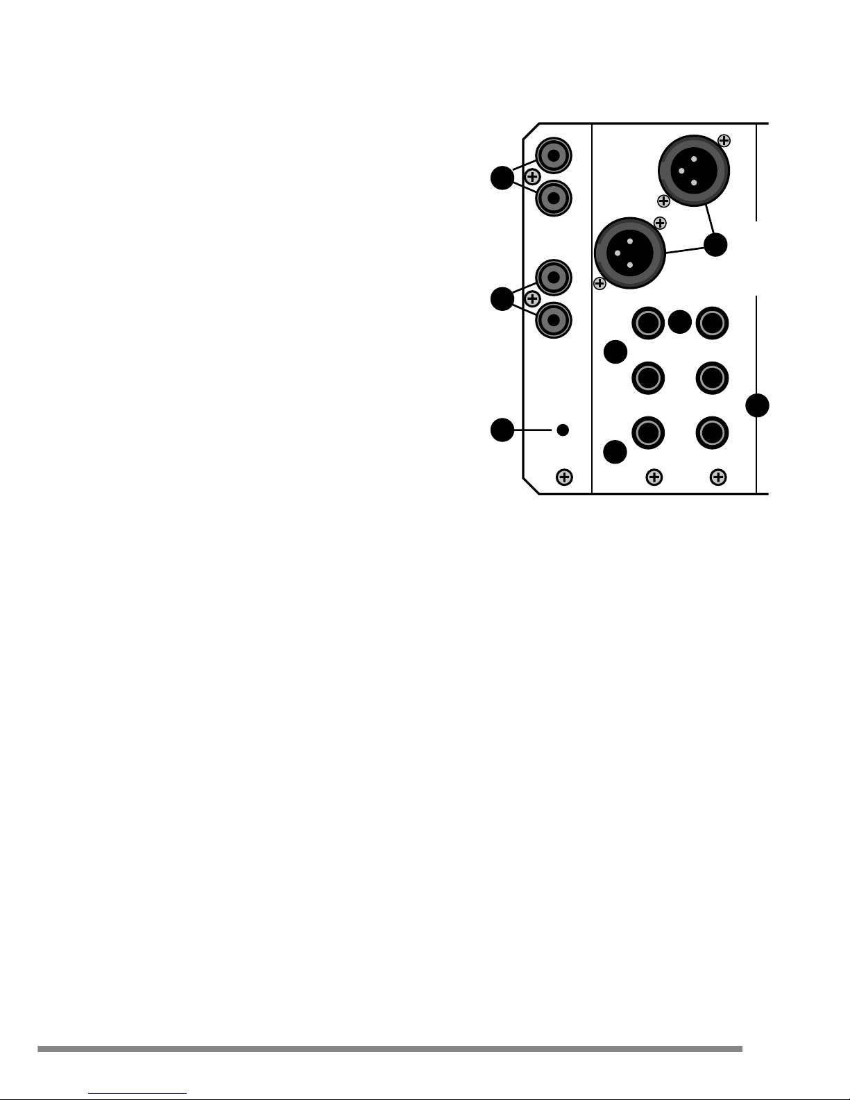
Controls & Features - Rear Panel Output Section
37 RECORD (L&R) : Unbalanced Phono (RCA) line level outputs
that can be connected to an external unit such as minidisc or
other recording equipment.
38 PLAYBACK (L&R) : Unbalanced Phono (RCA) line level
Left/Right inputs that route the output of a minidisc or CD player
back into the 162BPX main mix. Nominal input level -10dBV.
Note : Some recorders (minidisc / CD-R) internally route the input
signal back to the playback connectors to allow monitoring while
recording. If the machine you intend to use operates in this way,
disconnect the playback connectors from the 162BPX or a
feedback loop will occur.
39 +48V PHANTOM POWER : This recessed switch connects
standard 48V phantom power to mic inputs 1 to 12 for use with
capacitor/condenser mics or active DI boxes that require phantom
power.
Unbalanced mics must not be used when the phantom power is
switched on as damage may occur. The switch is recessed to
prevent accidental operation and should be operated using a
plastic ball-point pen or similar instrument. A warning LED (32) on
the front panel indicates that the Phantom Power is turned on.
If any channels require the 48V to be disconnected from channels
1 to 12 or added to channels 13 to 16 see options section.
40 OUTPUT (L&R) : Balanced XLR connectors to feed main PA
amplifier / multitrack recorder etc.
41 INSERT : A send/return for the main output on a single 1/4" TRS
(tip, ring, sleeve) jack. Use a 'Y' - cable to connect the tip to the
input and the ring to the output of a serial effects device
(compressor, equaliser, etc).
42 AUX SEND : Balanced compatible output on 1/4" TRS jack.
43 MON SEND : Balanced compatible output on 1/4" TRS jack.
44 AUX INPUT : Balanced stereo input on 1/4" TRS jacks for
minidisc/CD players, effect returns, drum machines etc.
For mono operation use LEFT/MONO connector only.
WHAT HAPPENS IF I PRESS THIS?
CONTROLS & FEATURES
5
EXPECT THE BEST
EXPECT THE BEST
37
38
39
40
41
INSERT
AUX INPUT
AUX
RECORD
PLAYBACK
+48V
SEND
SEND
MON
LEFT/
MONO
RIGHT
L
R
R
L
R
L
PHANTOM
POWER
BALANCED
+4dBu
OUTPUT
42
43
44
Page 8
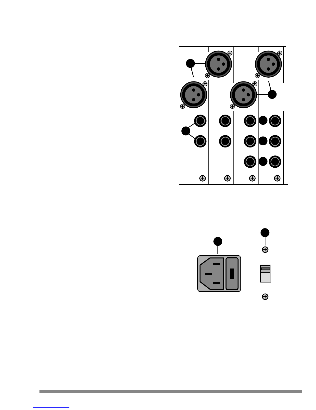
MIC
LINE
INSERT
DIRECT
OUT
11
MIC
LINE
INSERT
DIRECT
OUT
12
MIC
LEFT/ MONO
LINE
RIGHT
13
MIC
LEFT/ MONO
LINE
RIGHT
14
WHAT HAPPENS IF I PRESS THIS?
CONTROLS & FEATURES
6
www.studiomaster.com
www.studiomaster.com
Controls & Features - Rear Panel Input Section
45 MIC : MIC 3 pin XLR input - For balanced, low impedance
microphones.
48V phantom power may be applied globally to all Mic inputs by
depressing the recessed 48V switch on the rear panel using a
plastic ball-point pen or similar object. A status LED on the front
panel confirms that the phantom power is operational.
Do not use +48V phantom power with unbalanced mics
connected to the console.
If any channels require the +48V to be disconnected see
options section.
46 LINE Channels 1 - 12 : LINE 1/4" TRS jack input for use with
balanced, line level signals.
The line input is electronically balanced but may also be used
with unbalanced sources by simply plugging in an unbalanced
jack (TS) lead.
High impedance sources such as electric guitars should be fed
in via a DI box or suitable preamplifier for best results.
47 LINE (LEFT/MONO & RIGHT) Channels 13 - 16 : Line 1/4"
TRS jack for the connection of stereo line-level devices (drum
machines, keyboards, effect processors, etc). For mono
operation plug into the LEFT/MONO jack only.
The line input is electronically balanced by may also be used
with unbalanced sources by simply plugging in an unbalanced
jack (TS) lead.
48 INSERT : In effect a send/return for the channel on a single
1/4" TRS (tip, ring, sleeve) jack.
Use a 'Y' - cable to connect the tip to the input and the ring to
the output of an inline device (compressor, equaliser, etc).
49 DIRECT OUT : An output taken from the channel to be routed
elsewhere - multitrack recorder, monitor mixer, etc. The signal
is post - EQ and post - fader, so signal from the direct out is
exactly the same as that sent to the main outputs. (To change
the signal source see Options Section)
50 VOLTAGE SELECTOR : Do not adjust this switch when the
A.C. power cord / mains lead is connected. For supplies
between 220 and 240V use the 230V position. For supplies
between 110 and 120V use the 115V position.
51 POWER CONNECTOR : The A.C. power connector also
contains the internal A.C. power fuse.
45
47
46
48
49
45
230
51
50
Page 9

7
EXPECT THE BEST
EXPECT THE BEST
No power on LED.....
Check A.C. Power cord/mains lead is connected to wall supply and switched on.
UK Only - Check fuse in mains plug.
Check A.C. Power cord/mains lead is fully pushed into the rear panel socket (51).
Check it is switched on.
Check correct voltage is selected (50).
No Sound.....
Check for a signal on the meters.
Check the amplifier and speaker system is connected and switched on. Use headphones to check the
output of the 162BPX.
Check that the fader of the channel being used and the Main Mix faders are raised to 'normal' positions
(0dB).
Check the sound source - is it on?
Headphones distorting.....
Is the phones level set too high?
Are headphones being used with too low an impedance? 150-400 ohm types will give best performance,
32-50 ohm types can be used but may give lower maximum sound level.
WHY IS IT NOT WORKING!
TROUBLE SHOOTING
The following options are accessed by removing the front panel. ONLY qualified service personnel should
undertake this work.
Mono Mic channels (1 - 12)
Internally selectable AUX SEND Factory set : Post fader
Option : Pre fader (move JP1, marked on PCB)
MON SEND Factory set : Post EQ / Pre fader
Option : Pre EQ / Post fader (move JP2, marked on PCB)
DIRECT OUT Factory set : Post fader
Option : Pre EQ (move JP3, marked on PCB)
PHANTOM POWER Can be removed from individual channels (CONN3)
Mono / Stereo channels (13 - 16)
Internally selectable AUX SEND Factory set : Post fader
Option : Pre fader (move JP1, marked on PCB)
MON SEND Factory set : Post EQ / Pre fader
Option : Pre EQ / Post fader (move JP2, marked on PCB)
PHANTOM POWER Can be added to individual channels (CONN4)
SERVICE CENTRES ONLY
INTERNAL OPTIONS
Page 10
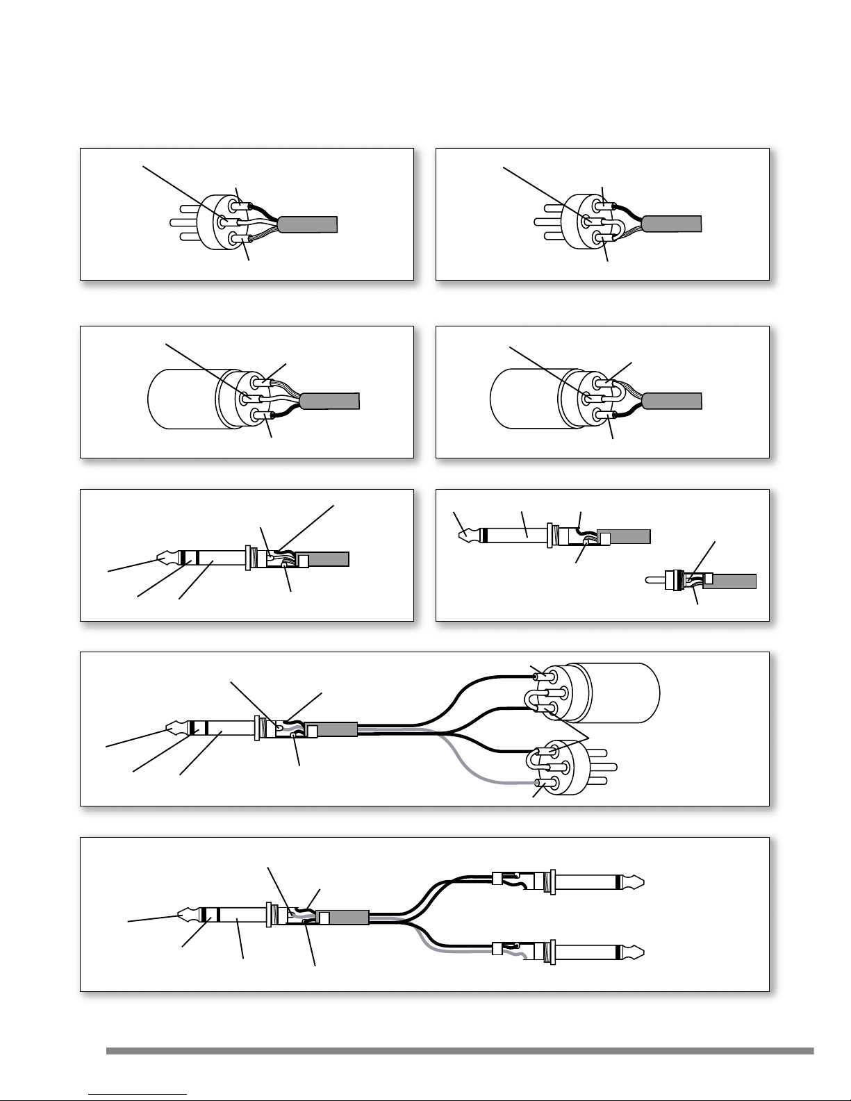
HOW DO I KNOW I HAVE THE RIGHT LEADS
WIRING CONNECTIONS
8
www.studiomaster.com
www.studiomaster.com
Pin 3 - Negative / Cold / -Ve phase
Ring - Negative / Cold / -Ve phase
Pin 2 - Positive / Hot / +Ve phase
Pin 1 - Screen / Ground / Earth
Pin 3 - Link to Pin 1
Pin 2 - Positive / Hot / +Ve phase
Pin 1 - Screen / Ground / Earth
Pin 3 - Negative / Cold / -Ve phase
Pin 1 - Screen / Ground / Earth
Pin 2 - Positive / Hot / +Ve phase
Pin 3 - Link to Pin 1
Pin 1 - Screen / Ground / Earth
Pin 2 - Positive / Hot / +Ve phase
Tip - Positive / Hot / +Ve phase
Sleeve - Screen / Ground / Earth
Tip
Ring
Sleeve
Tip - Signal
Tip
Tip - SignalSleeve
Sleeve - Screen / Ground / Earth
Sleeve - Screen / Ground / Earth
Female XLR from
processor output
Male XLR to
processor input
JACK from
processor output
JACK to
processor input
Ring - Output from mixer
Tip - Amplifier Input
Pin 3 - Signal
Pin 1 - Screen / Ground / Earth
Link to Pin 2
Pin 3 - Signal
Sleeve - Screen / Ground / Earth
Tip - Amplifier Input
Sleeve - Screen / Ground / Earth
Tip
Ring
Sleeve
Sleeve
Ring - Output from mixer
Ring
Tip
To connect a Balanced Microphone
to a mic input 3 pin XLR - male
To connect an Unbalanced Microphone
to a mic input 3 pin XLR - male
To connect a Balanced Microphone
to a mic input 3 pin XLR - female
To connect an Unbalanced Microphone
to a mic input 3 pin XLR - female
To connect Balanced equipment to an input or output
To connect an external Processor with XLR input / output to an INSERT (SEND/RETURN) socket
To connect an external Processor with JACK input / output to an INSERT (SEND/RETURN) socket
To connect Unbalanced equipment to an input or output
Page 11

9
EXPECT THE BEST
EXPECT THE BEST
FACTS & FIGURES
TECHNICAL SPECIFICATION
Input Gain Min Max Range
Mic (to L/R) 2dB 60dB 48dB
Line (to L/R) -8dB 40dB 48dB
Stereo Line (to L/R) 0dB 12dB 12dB
Equalisation (all +/-15dB) Lo Mid Hi
Mic Channels 60Hz 250Hz-6kHz 12kHz
Stereo Input 45Hz - 12kHz
Frequency Response (any Input) 10Hz - 45kHz +/-0.5dB
Distortion (any Input) 0.03%
Noise
Mic EIN -128dBu
Signal to noise ratio >85dB (unweighted) with typical control settings
Dynamic range >108dB
DSP
Reverb mode 3 Vocal, 1 ADT, 2 Reverb
Delay mode 6 settings between 100ms and 720ms
Metering Peak reading 12 segment 3 colour LED bargraphs
Maximum Input Level At Max gain At Min gain
Mic -38dBu +10dBu
Line -21dBu +28dBu
Stereo Line +10dBu +22dBu
Aux Input +16dBu +22dBu
Output Levels Nominal Maximum Impedance
Mono Insert +4dBu +22dBu <22 ohms
Aux Sends 1/2 - +22dBu 100 ohms
L/R Outputs +4dBu +28dBu 75 ohms
L/R Insert -2dBu +22dBu <22 ohms
Phones - +22dBu 33 ohms
Power Supply
230V range +/-10%, ~50/60Hz, 150mA Max
115V range +/-10%, ~50/60Hz, 300mA Max
Dimensions
Width 482mm (19")
Height 266mm (10.5") when racked, the unit occupies 6 rack spaces (6U)
Depth 120mm (4.8")
Weight
Net 7kg (15.4lbs)
Shipping 8.2kg (18.1lbs)
Page 12

The Manufacturer warrants all Studiomaster products to be free from defects in materials and workmanship for a
period of one year from date of purchase. The Manufacturer reserves the right to the final decision on all
warranty claims.
Exclusions to Warranty Cover
Damage caused by accident, misuse, improper installation or neglect.
Damage caused by repair, modification or service by persons not authorised by Studiomaster.
Products on which the serial number has been defaced, altered or removed.
Who is Protected
This warranty is enforceable by the original purchaser and any subsequent owner(s) during the warranty period,
providing a copy of the original sales receipt is submitted whenever a warranty service is required.
It is recommended that you complete and mail the Warranty Registration Card supplied with your product.
For your reference in the event of a warranty or service repair, please complete the following information and
attach a copy or your original sales receipt.
Model :
Serial Number :
Purchase Date :
Purchased From :
Note : THIS WARRANTY DOES NOT AFFECT YOUR STATUTORY RIGHTS
ARE YOU COVERED?
WARRANTY
10
www.studiomaster.com
www.studiomaster.com
Page 13

If you have a problem with your Studiomaster product or think it has developed a fault you should first carefully
check the Trouble Shooting section in this guide. If this does not solve the problem or if the product is physically
damaged, contact your local dealer or distributor for service details.
Should it be recommended you return the product to your nearest Studiomaster Service Centre you must first
contact them.
You will be asked for the product type and serial number. You will then be given a Returns Authorisation (RA)
number.
Pack the unit in its original carton to protect it from shipping damage.
You must have the Returns Authorisation number clearly marked on the outside of the carton or we may refuse the
delivery. Studiomaster cannot be held responsible for damage resulting from the equipment being packed
incorrectly.
Label the equipment clearly with your name and address and include a clear description of the fault. The more
information you supply helps the service engineer, minimising repair cost when out of warranty.
Important : No liability will be accepted by Studiomaster for any transit damage to units not returned in their original
packing, for warranty repairs or otherwise.
HOW TO GET MY PRODUCT REPAIRED
SERVICE INFORMATION
11
EXPECT THE BEST
EXPECT THE BEST
Page 14

NOTES
NOTES
12
www.studiomaster.com
www.studiomaster.com
Page 15

In Accordance with our progressive product development, Studiomaster / Studioking Limited
reserve the right to change features and specifications without prior notice.
EXPECT THE BEST
EXPECT THE BEST
Page 16
www.studiomaster.com
Studioking Limited
7 Eden Way, Pages Industrial Park, Leighton Buzzard, Bedfordshire LU7 4TZ UK
Tel : 44 (0)1525 217111 Fax : 44 (0)1525 378466 Email : [email protected]
EXPECT THE BEST
EXPECT THE BEST
162BPXM ENG V1
+10
0
-5
-10
-20
-30
8
+5
0
-5
-20
-30
+5
0
-5
-20
-30
+5
0
-5
-20
-30
+5
0
-5
-20
-30
+5
0
-5
-20
-30
+5
0
-5
-20
-30
+5
0
-5
-20
-30
+5
0
-5
-20
-30
+5
0
-5
-20
-30
+5
+10
-10
8
+10
-10
8
+10
-10
8
+10
-10
8
+10
-10
8
+10
-10
8
+10
-10
8
+10
-10
8
+10
-10
8
1K
1K5600
3K350
1K
1K
5
600
3
K
350
PFL P
F
PEAK PEAK
40
20
GAIN
-
+
12 60dB
HI
12K
4
20
GAIN
-
+
12 60
d
HI
12K
-
+
0 10
0 10
LR
LO
60Hz
PAN
-
+
0 10
0 10
LR
LO
60Hz
PAN
-
+
MID
-
+
MID
250Hz 6KHz 250Hz 6KH
z
30 30
AUX/
DSP
MON
AUX/
DSP
MON
40
30 30
20
-
+
-
+
-
+
1K
1K5600
3K350
1K
1K5600
3K350
1K
1K5600
3K350
1K
1K5600
3K350
1K
1K5600
3K350
1K
1K5600
3K350
1K
1K5600
3K350
1K
1K5600
3K350
-
+
0 10
0 10
LR
LO
60Hz
AUX/
DSP
MON
PAN
12 60dB
MID
PFLPFL PFL PFL PFL PFL PFL PFL
PEAK PEAK PEAK PEAK PEAK PEAK PEAK PEAK
HI
12K
40
20
GAINGAIN
-
+
12 60dB
HI
12K
40
20
GAIN
-
+
12 60dB
HI
12K
40
20
GAIN
-
+
12 60dB
HI
12K
40
20
GAIN
-
+
12 60dB
HI
12K
40
20
GAIN
-
+
12 60dB
HI
12K
40
20
-
+
12 60dB
HI
12K
40
20
GAIN
-
+
12 60dB
HI
12K
-
+
0 10
0 10
LR
LO
60Hz
PAN
-
+
0 10
0 10
LR
LO
60Hz
PAN
-
+
0 10
0 10
LR
LO
60Hz
PAN
-
+
0 10
0 10
LR
LO
60Hz
PAN
-
+
0 10
0 10
LR
LO
60Hz
PAN
-
+
0 10
0 10
LR
LO
60Hz
PAN
-
+
0 10
0 10
LR
LO
60Hz
PAN
MID
-
+
MID
-
+
MID
-
+
MID
-
+
MID
-
+
MID
-
+
MID
250Hz 6KHz 250Hz 6KHz 250Hz 6KHz 250Hz 6KHz 250Hz 6KHz 250Hz 6KHz 250Hz 6KHz 250Hz 6KHz
30 30 30 30 3030
AUX/
DSP
MON
AUX/
DSP
MON
AUX/
DSP
MON
AUX/
DSP
MON
AUX/
DSP
MON
AUX/
DSP
MON
AUX/
DSP
MON
10987654321
 Loading...