

Page 1

Small Products Technical Manual
for Powered and Passive Panels
Page 2

Page 3

Table of Contents
Part # Page
StudioHub+ Standard Pinout
& Power Consumptions Illustration 3
How to Power StudioHub+ - via PS-Cube 4
How to Power StudioHub+ - via a Hub or Wall-Wart 5
Active (Powered) MatchJacks
MatchJack Preamp, Input MJ-IN 6
MatchJack Preamp, Output MJ-OUT 7
AES/EBU to S/PDIF Converter MJ-SPDIFIN 8
S/PDIF to AES/EBU Converter MJ-SPDIFOUT 9
Analog to Digital Converter MJ-AD 10
Digital to Analog Converter MJ-DA 11
Digital Distribution Amplifier MJ-DDA 12
Passive Panels
Dual XLR Female Adapter Mono/Stereo SH-2XLRF 13
Dual XLR Male Adapter Mono/Stereo SH-2XLRM 14
Dual XLR Male-Female Panel SH-2XLRMF 15
Single XLR Female Panel SH-1XLRF 16
Single XLR Male Panel SH-1XLRM 17
Single XLR 5-Pin Female Panel SH-1XLRF5PIN 18
Dual XLR Female Panel (Stereo Only)* 19
Dual XLR Male Panel (Stereo Only)* 20
1/4” & Mini TRS Panel
1/4” & Mini TRS Panel
4 Source Switcher Panel SH-4SW* 23
Breakout Adapter ADAPT-BO 24
Breakout Adapter ADAPT-GPI 25
PS-CUBE “DC-Link” Power Inserter PS-CUBE 26
(Unbalanced)
(Balanced)
SH-1/4BAL 22
SH-1/4UNBAL 21
* Obsolete Part
Active (Powered) Panels Part # Page
4 Source Switcher Panel SH-4SHSS 27
Mic Preamp Panel SH-MIC 28
Mic Preamp w/PTT Panel SH-MICPTT 29
Headphone Amplifier Panel SH-HPB 30
Dual Headphone Amp. Panel SH-HPDUAL 31
Monitor Level Control Panel SH-LEVEL 32
Monitor Amp Panel SH-AMP w/o Speaker 33
SH-AMPSPKR w/Speaker 33
Dual VU Meter Panel SH-VUV(Vertical) 34
SH-VUH (Horizontal) 34
3 Mixer Panel (Input) SH-MIXER 35
3 Mixer Panel (Output) SH-MIXER 36
LCD Display Panel SH-LCDV(Vertical) 37
S
In/Out Balanced MatchJack SH-DUALMATCH 38
In/Out Balanced MatchJack SH-MATCHPANEL 39
Warranty/Repair Policy/Returns
H-LCDH(Horizontal) 37
2
Page 4
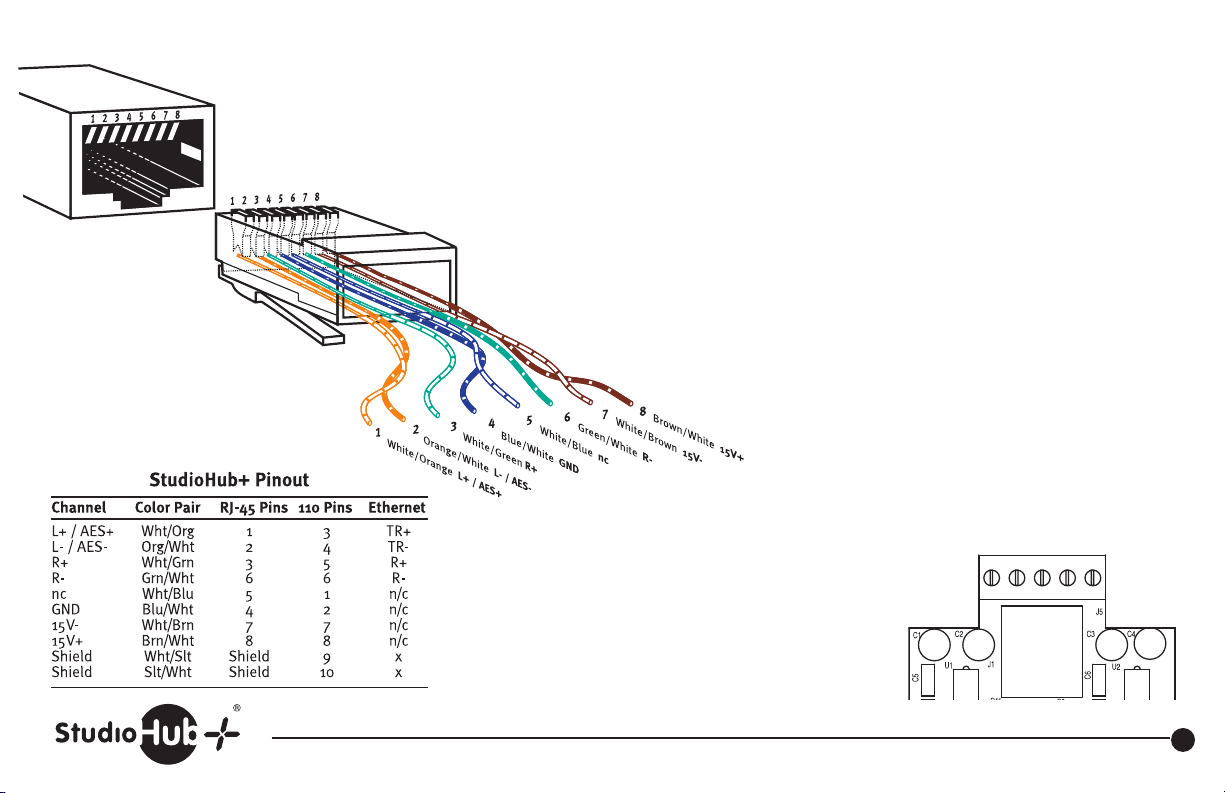
StudioHub+
Standard Pinout
(T568B Standard)
Current consumption for each StudioHub+ active device. Refer to this list
when calculating the total number of devices that can be run together
on any individual power supply.
Part # Description Current
MJ-OUT Analog MatchJack Out (IHF to Pro) 75ma
MJ-IN Analog MatchJack In (Pro to IHF) 35ma
MJ-SPDIFOUT SPDIF OUT (S/PDIF and Optical to AES) 100ma
MJ-SPDIFIN SPDIF IN (AES to S/PDIF) 0 (passive)
MJ-AD Digital MatchJack A to D 150ma
MJ-DA Digital MatchJack D to A 150ma
MJ-DDA Digital MatchJack Distribution Amplifier 165ma*
SH-DUALMATCH Dual Match Panel 100ma
SH-HP Headphone Panel 100ma
SH-MIC Mic Pre-Amp Panel 55ma
SH-MIXER 3 Input Stereo Mixer with mix-minus 125ma
SH-AMPSPKR Monitor Amp Panel (w/ Speaker) 1400ma
SH-LEVEL Monitor Panel 145ma
SH-VUV Dual VU Meter Panel 150ma
SH-LCDV LCD Display Panel 75ma
DA6-DC DA Hub (Single) 575ma
SUM4-DC Combiner Hub (Single) 175ma
* Powered via 9v DC (single ended) wall wart
or +/-15vDC StudioHub+ power supply
LEFT RIGHT
+ - G - +
Stand-Alone Versions
Some active StudioHub+ products were
previously available in “Stand-Alone”
versions with barrier strip connectivity for
audio I/O. The following illustrates the
pinout for this barrier strip.
(856) 467-8000 • Fax (856) 467-3044 • www.studiohub.com
3
Page 5
Revised 4-21-10
s
Powering StudioHub+ Active Devices
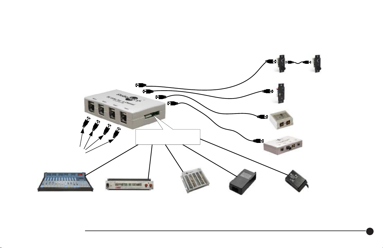
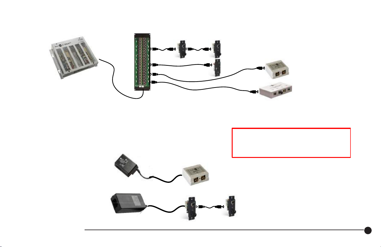
Many StudioHub+ devices are active and are powered by +/- 15vDC. Power can be supplied via the StudioHub+ “DC-Link”
system that uses CAT-5 pair #4 (White/Brown) for power, or power can be supplied via a separate power supply.
See the current consumption chart to determine how many devices can be powered with different systems.
I - Po wering v ia PS-Cube (for up to 4 devices)
PS-Cube
5-pin MTA & 3-pin MTE
power connectors (in parallel)
From 4 separate
udio sends or feed
1 Amp
Power a PS-CUBE from a
Radio Systems Console
se cable # 16998(6') / 15884(1')
(3-pin MTA to 3-pin MTE)
Power a PS-CUBE from a
RS Console Power Supply
(16-pin MR-16 to 5-pin MTA)
1 Amp
Use cable # 16600
3 Amps
Power a PS-CUBE from a
PS-EXTU Power Supply
(the cable is included)
(4-pin MR-4 to 5-pin MTA)
Headphone amps link
together for audio & DC
SH-MIC
MatchJack
D to A
Converter
400 ma
Power a PS-CUBE from a
PS-WWUCUBE Power Supply
(the captive cable is included)
(captive to 3-pin MTE)
200 ma
Power a PS-CUBE from a
PS-WWCUBE Power Supply
(the captive cable is included)
(captive to 3-pin MTE)
How to Power StudioHub+ - via PS-Cube
4
Page 6
s
s
Power a PS-CUBE from a
Radio Systems Console
se cable # 16998(6') / 15884(1')
(3-pin MTA to 3-pin MTE)
Power a PS-CUBE from a
RS Console Power Supply
Use cable # 16600
(16-pin MR-16 to 5-pin MTA)
Power a PS-CUBE from a
PS-EXTU Power Supply
(the cable is included)
(4-pin MR-4 to 5-pin MTA)
Power a PS-CUBE from a
PS-WWCUBE Power Supply
(the captive cable is included)
(captive to 3-pin MTE)
Power a PS-CUBE from a
PS-WWUCUBE Power Supply
(the captive cable is included)
(captive to 3-pin MTE)
II - Powering Via a Hub (for up to 16 devices)
SH-HP
SH-HP
Headphone amps link
together for audio & DC
Revised 4-21-10
PS-EXTU
3 amp bi-polar
15vDC power supply
Use any Hub in which the model number ends in “DC”
(HUB18-DC or HUB36-DC or HUB8-DC or HUB16-DC
III - Powering via a “Wall Wart” o r Desk-Top Power Supply
ower an individual MatchJack or Panel
from a PSWW-SH Power Supply
(the captive 3-pin to MTA cable
from a PSWWU-SH Power Supply
(the captive 3-pin to MTA cable
is included)
Power multiple Panels
is included)
SH-HP
SH-MIC
NOTE – All power supplies shown are Universal Voltage
switching supplies and accept from 100 to 240VAC input
power EXCEPT the “non Universal Wall-Wart”
PS-WWCUBE and PS-WWSH supplies
which are 110VAC input power only.
SH-HP
MatchJack
D to A
Converter
SH-HP
MatchJack
SH-HP
Headphone amps link together for audio & DC.
Power up to 4 headphone amps from one PS-WWU
and up to 2 headphone amps from 1 PSWW
How to Power StudioHub+ - via a Hub or Wall-Wart
5
Page 7
Revised 4-21-10
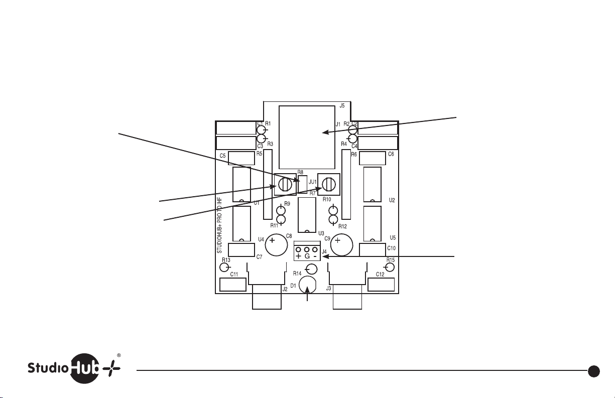
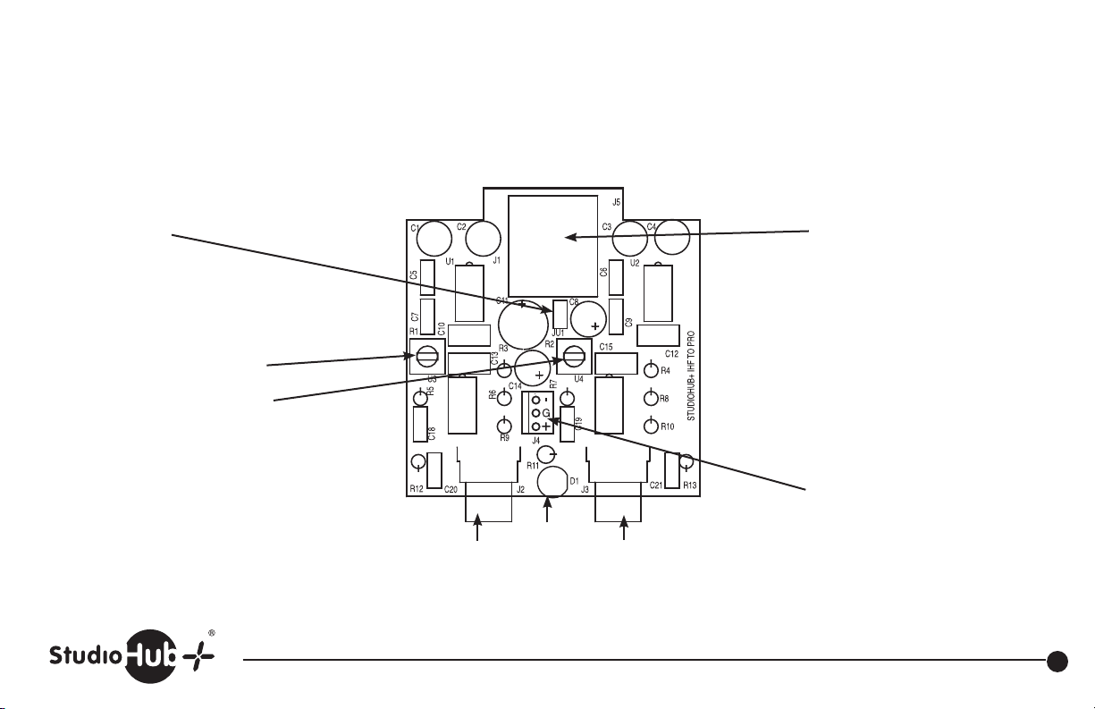
JU1
Install to connect shield ground
to power ground
Left level adjust
Right level adjust
Left output RCA
Power
LED
Audio and power input
provided on RJ-45
Direct power input
+/- 15 volts DC
Right output RCA
Part # MJ-IN StudioHub+ MatchJack Preamp, Input
(856) 467-8000 • Fax (856) 467-3044 • www.studiohub.com
6
Page 8
Revised 4-21-10
JU1
Install to connect
shield ground to
power ground
Left level adjust
Right level adjust
Audio and power input
provided on RJ-45
Direct power input
+/- 15 volts DC
Power
Right input RCALeft input RCA
LED
Part # MJ-OUT StudioHub+ MatchJack Preamp, Output
(856) 467-8000 • Fax (856) 467-3044 • www.studiohub.com
7
Page 9
Revised 4-21-10
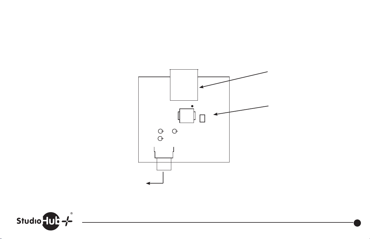
* RCA S/PDIF output
ASM
J1
J2
T1
JU1
StudioHub+ AES/EBU RJ-45 input
JU1
Install to connect
shield ground to
power ground
R1 R1
R2
J3
Part # MJ-SPDIFIN StudioHub+ S/PDIF to AES/EBU Converter
(856) 467-8000 • Fax (856) 467-3044 • www.studiohub.com
8
Page 10
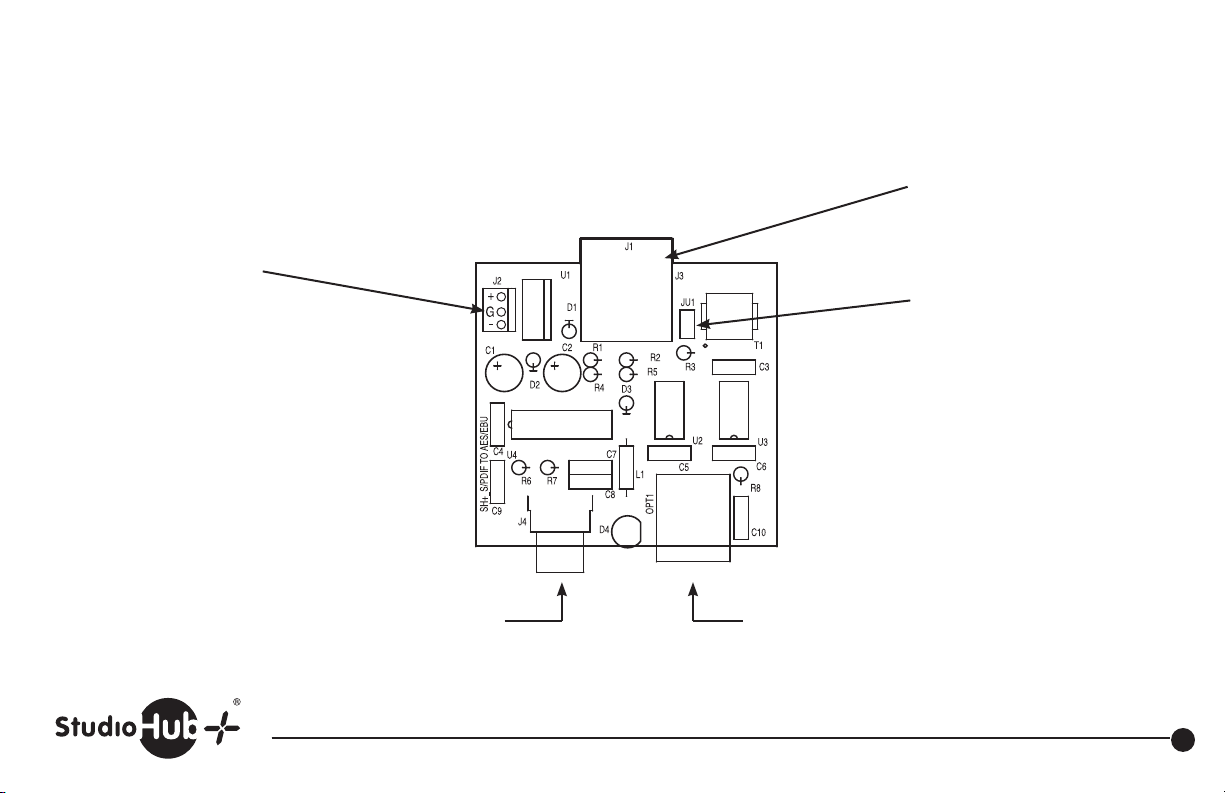
Direct power in
+/- 15 volts DC
Revised 4-21-10
StudioHub+ AES/EBU
output and power in
JU1
Install to connect
shield ground to
power ground
* RCA S/PDIF input *Optical Input
Part # MJ-SPDIFOUT StudioHub+ S/PDIF to AES/EBU Converter
(856) 467-8000 • Fax (856) 467-3044 • www.studiohub.com
* Use only one
9
Page 11
Pro Level Input
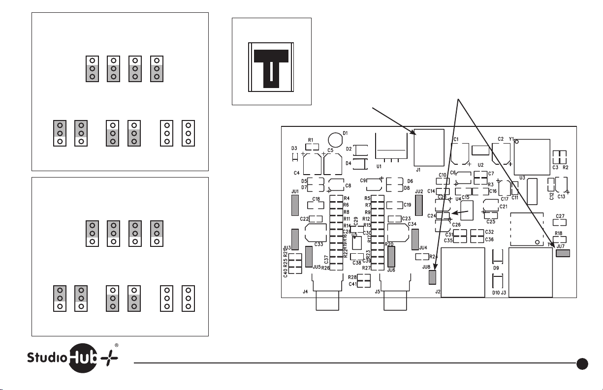
Set Input Level
JU3 JU4 JU5 JU6
IHF
PRO
Short all lower pins
Set Nominal Input Sensitivity*
JU1 JU2 JU1 JU2 JU1 JU2
Power Supply Connector
REDBLUWHT
+15vG-15v
DC power in +/- 15 volts DC included
(Radio Systems Part # PS-UCUBE)
Unit can also be powered by
StudioHub+ “DC-Link” via RJ-45’s.
Revised 10-30-15
JU7, JU8
Install to connect RJ-45 shield
to ground to power ground
C
D
0dBu
Short Upper Pins Short Lower Pins Short No Pins
C
D
C
D
+4dBu +8dBu
Consumer Level Input
Set Input Level
JU3 JU4 JU5 JU6
IHF
PRO
Short all upper pins
Set Nominal Input Sensitivity*
JU1 JU2 JU1 JU2 JU1 JU2
C
D
-15dBv
Short Upper Pins Short Lower Pins
C
D
C
D
-10dBv -6dBv
Short No Pins
* Set for station standard
reference level to provide unit
output headroom of 20dB.
Unbalanced Inputs
Balanced
Input
AES/EBU
Output
Left Right
Part # MJ-AD StudioHub+ Analog to Digital Converter
(856) 467-8000 • Fax (856) 467-3044 • www.studiohub.com
10
Page 12
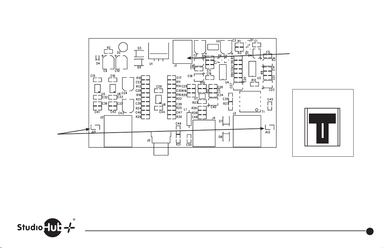
JU1 and Ju2
Install to connect
RJ-45 shield
to ground
Analog Output
Revised 10-30-15
DC power in +/- 15 volts DC
included
(Radio Systems Part # PS-UCUBE)
Unit can also be powered by
StudioHub+ “DC-Link” via RJ-45’s.
Power Supply Connector
REDBLUWHT
+15vG-15v
AES/EBU InputTOSlink InputCoaxial Input
Part # MJ-DA StudioHub+ Digital to Analog Converter
(856) 467-8000 • Fax (856) 467-3044 • www.studiohub.com
11
Page 13
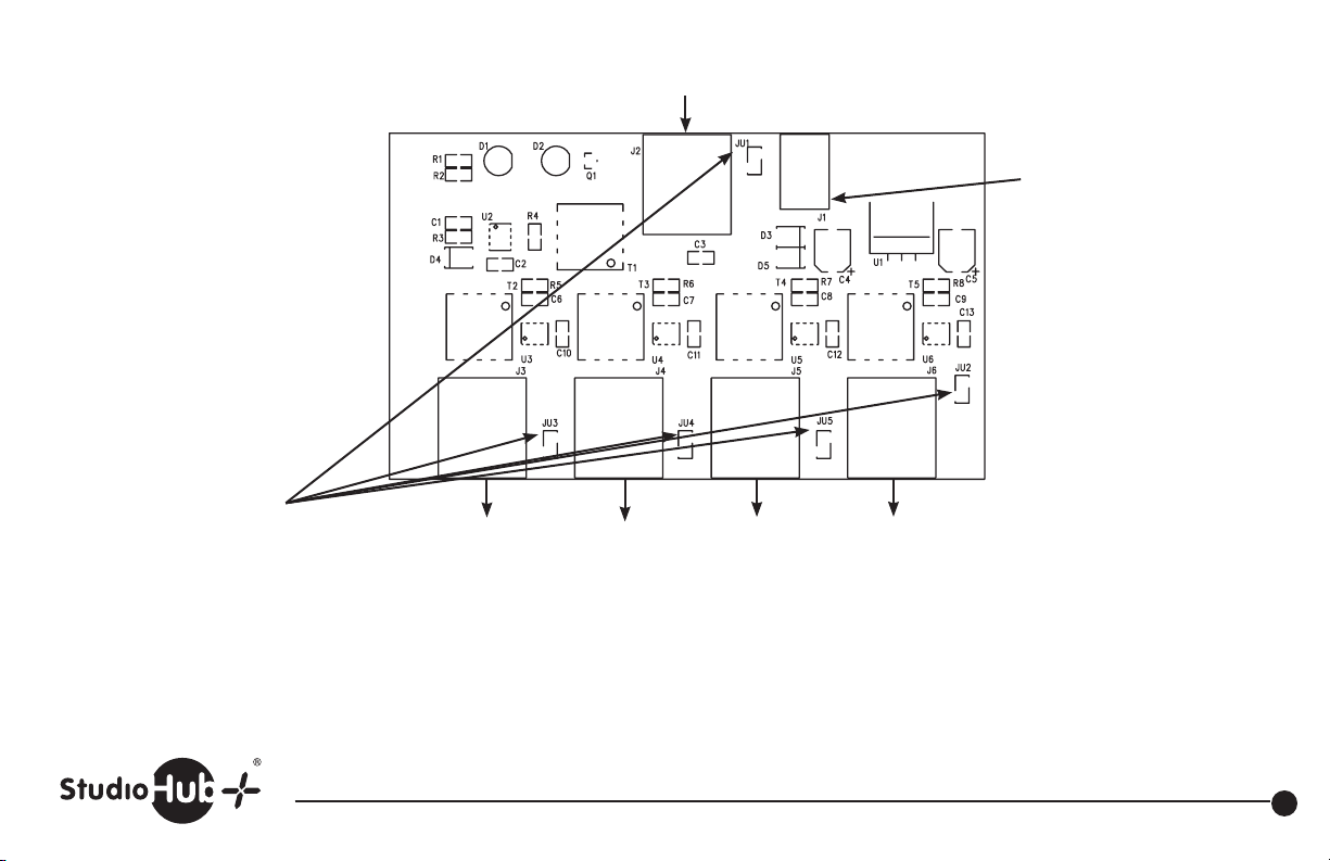
JU1 - Ju5
Install to connect
RJ-45 shield
to ground
AES Input
AES Output #1 AES Output #2 AES Output #3
Revised 10-30-15
DC power in +9 volts DC included.
(Radio Systems Part # 16213).
Unit can also be powered by
StudioHub+ “DC-Link” via RJ-45’s
AES Output #4
Part #
MJ-DDA StudioHub+ Digital Distribution Amplifier
(856) 467-8000 • Fax (856) 467-3044 • www.studiohub.com
12
Page 14

When programmed for stereo operation:
8
7
6
5
4
3
2
1
2
1
3
2
1
3
8
7
6
5
4
3
2
1
Left
XLR
Right
XLR
CHASSIS
GROUND
RJ-45 #2
JU3
JU1
RJ-45 #1
JU2
JU4
CHASSIS
GROUND
CHASSIS
GROUND
L & R XLR feed both RJ45’s in stereo.
1
2
Right
XLR
CHASSIS
GROUND
Left
XLR
3
1
2
3
CHASSIS
GROUND
JU1
JU3
8
7
6
5
4
3
2
1
RJ-45 #1
CHASSIS
GROUND
JU4
JU2
8
7
6
5
4
3
2
1
RJ-45 #2
When programmed for Mono Operation:
Left XLR feeds RJ45-1, pins 1 & 2 only.
Right XLR feeds RJ45-2, pins 1 & 2 only.
8
7
6
JU1
JU3
5
4
3
2
1
RJ-45 #1
Right
XLR
CHASSIS
GROUND
Left
XLR
2
CHASSIS
GROUND
1
3
CHASSIS
GROUND
Revised 4-21-10
8
7
6
JU2
JU4
5
4
3
2
1
RJ-45 #2
1
2
3
CHASSIS
GROUND
To configure for stereo operation
JU5
JU6
JU7, JU8, JU9, JU10
XLR PIN1 select jumper
Install JU3 to connect
Left XLR pin 1 to chassis ground
Install JU4 to connect
Right XLR pin 1 to chassis ground
StudioHub+ RJ45 “A” for mono only
or stereo operation
Part # SH-2XLRF StudioHub+ Dual XLR Female Adapter Mono/Stereo
StudioHub+ RJ45 “B”
for stereo operation
(856) 467-8000 • Fax (856) 467-3044 • www.studiohub.com
To configure for mono operation
JU5
JU6
JU7, JU8, JU9, JU10
RJ45 shield and ground select jumpers
Left Right
JU1 JU2
Install to connect
XLR Pin 1 to RJ-45 shield
JU1 JU2
Install to connect
XLR Pin 1 to RJ-45
power ground (RJ-45 pin 4)
13
Page 15
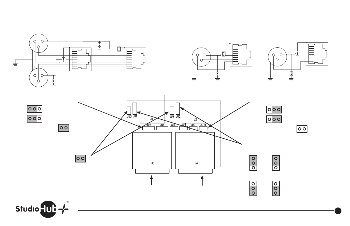
When programmed for stereo operation:
8
7
6
5
4
3
2
1
2
1
3
2
1
3
8
7
6
5
4
3
2
1
Left
XLR
Right
XLR
CHASSIS
GROUND
RJ-45 #2
JU3
JU1
RJ-45 #1
JU2
JU4
CHASSIS
GROUND
CHASSIS
GROUND
L & R XLR feed both RJ45’s in stereo.
1
2
Right
XLR
CHASSIS
GROUND
Left
XLR
3
1
2
3
CHASSIS
GROUND
JU1
JU3
8
7
6
5
4
3
2
1
RJ-45 #1
To configure for stereo operation
JU5
JU6
JU7, JU8, JU9, JU10
XLR PIN1 select jumper
Install JU3 to connect
Left XLR pin 1 to chassis ground
Install JU4 to connect
Right XLR pin 1 to chassis ground
JU4
JU2
CHASSIS
GROUND
8
7
6
5
4
3
2
1
RJ-45 #2
StudioHub+ RJ45 “A” for mono only
or stereo operation
Part # SH-2XLRM StudioHub+ Dual XLR Male Adapter Mono/Stereo
When programmed for mono operation:
Left XLR feeds RJ45-1, pins 1 & 2 only.
Right XLR feeds RJ45-2, pins 1 & 2 only.
8
7
6
JU1
JU3
5
4
3
2
1
RJ-45 #1
Right
XLR
Left
XLR
2
CHASSIS
GROUND
1
3
CHASSIS
GROUND
To configure for mono operation
JU5
JU6
JU7, JU8, JU9, JU10
RJ45 shield and ground select jumpers
Left Right
JU1 JU2
JU1 JU2
JU1 JU2
StudioHub+ RJ45 “B”
for stereo operation
(856) 467-8000 • Fax (856) 467-3044 • www.studiohub.com
2
CHASSIS
GROUND
Revised 4-21-10
8
7
6
JU2
JU4
5
4
3
2
1
RJ-45 #2
1
3
CHASSIS
GROUND
Install to connect
XLR Pin 1 to RJ-45 shield
Install to connect XLR Pin 1
to RJ-45 power ground
(RJ-45 pin 4)
14
Page 16
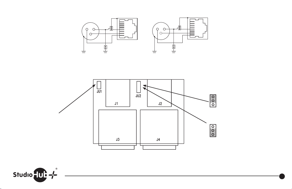
Revised 4-21-10
Install JU1 to connect XLR(s)
pin 1 to chassis ground
Female
XLR
2
CHASSIS
GROUND
JU1
8
7
6
5
4
3
2
1
RJ-45 #2
8
7
6
JU2
1
3
5
4
3
2
1
Male
XLR
2
3
JU2
1
RJ-45 #1
JU1
CHASSIS
GROUND
CHASSIS
GROUND
CHASSIS
GROUND
RJ45-1 RJ45-2
JU2
Install to connect XLR(s) pin 1
to StudioHub+ RJ45 shield
JU2
Install to connect XLR(s) pin 1
to StudioHub+ RJ45
power ground (RJ-45 pin 4)
Female XLR Male XLR
Part# SH-2XLRMF StudioHub+ Dual XLR Male/Female Panel
(856) 467-8000 • Fax (856) 467-3044 • www.studiohub.com
15
Page 17
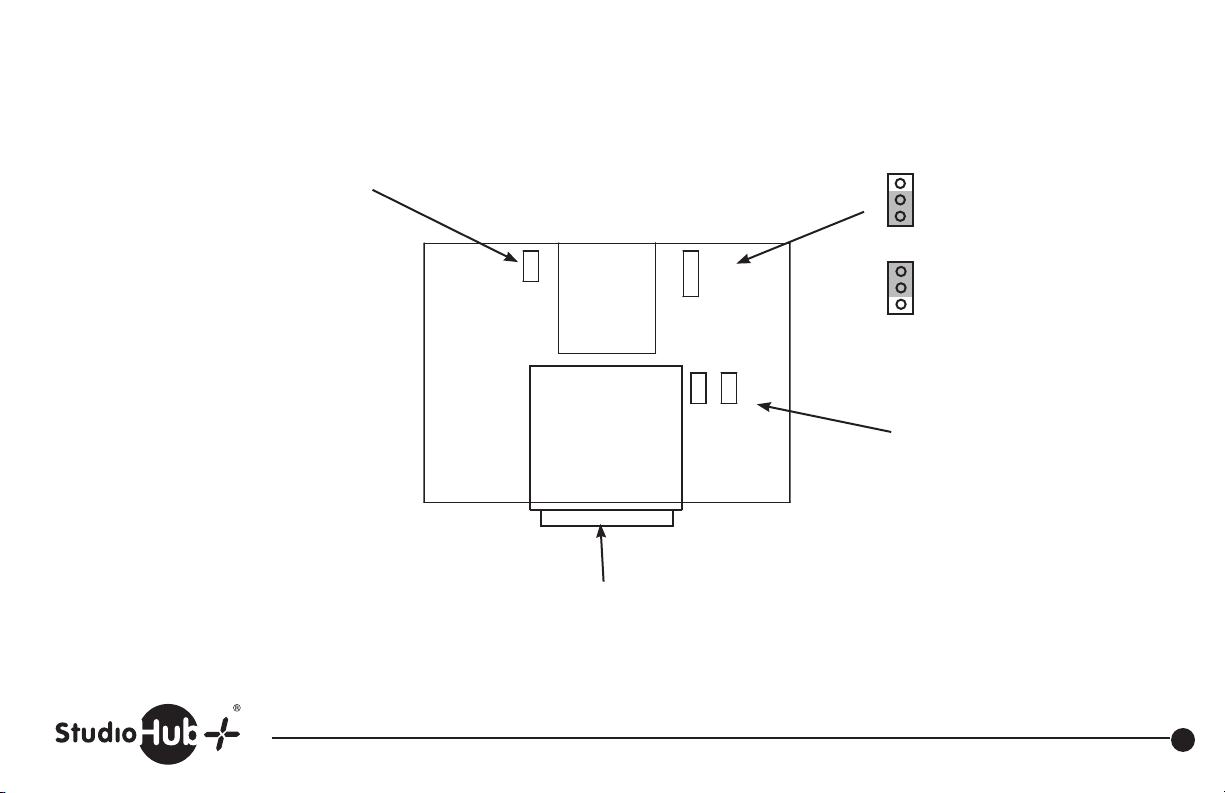
Revised 4-21-10
JU1
Install to connect XLR pins to chassis ground
STUDIOHUB+
F XLR TO RJ45
JU2
Install to connect XLR pins to
power ground
JU2
JU1
J1
JU4JU3
Install to connect XLR pin 1 to
shield ground
JU3, JU4
J2
Install for left and right in parallel
Remove for left only
XLR
Part # SH-1XLRF StudioHub+ Single XLR Female Panel
(856) 467-8000 • Fax (856) 467-3044 • www.studiohub.com
16
Page 18
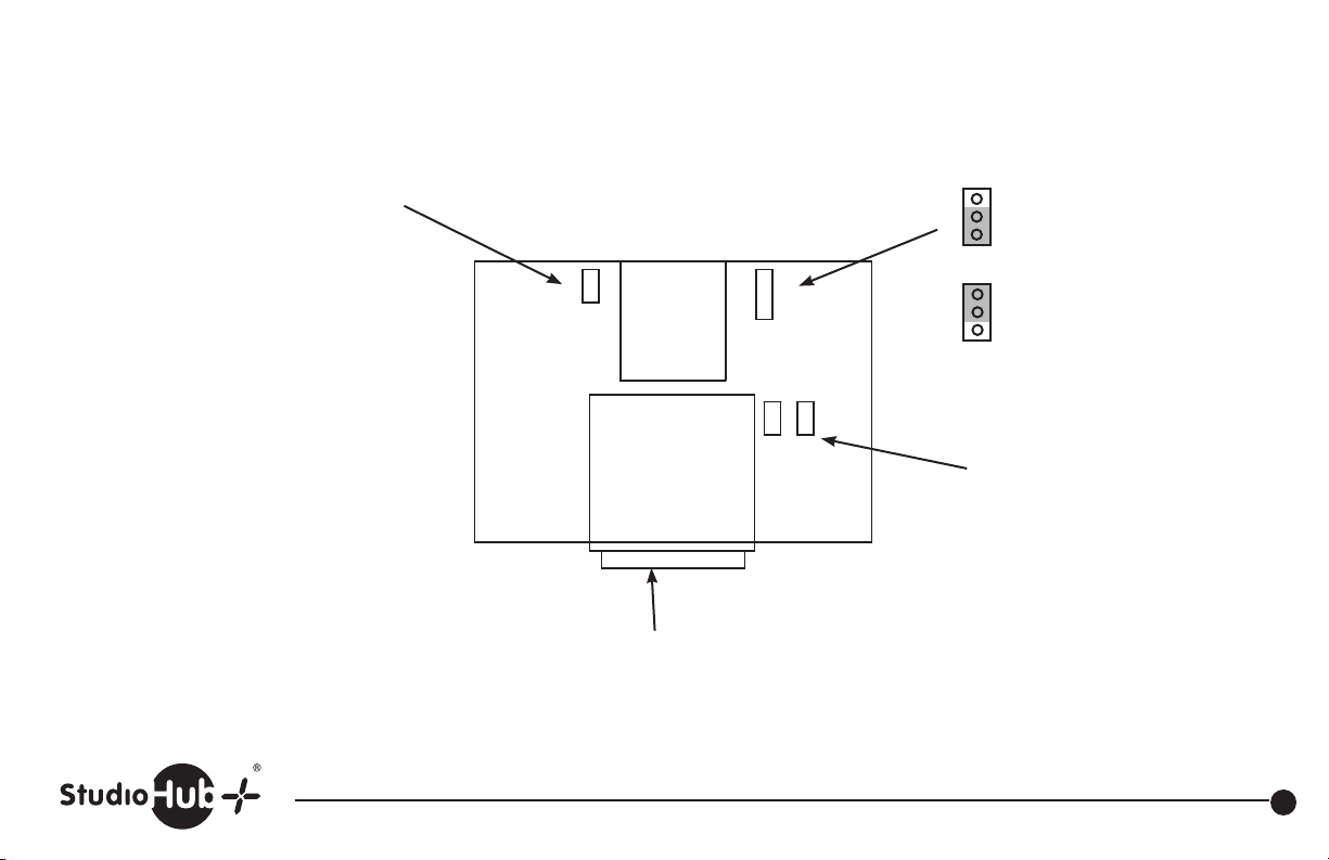
Revised 4-21-10
JU1
Install to connect XLR pins to chassis ground
STUDIOHUB+
M XLR TO RJ45
JU2
Install to connect XLR pins to
power ground
JU2
JU1
J1
JU4JU3
Install to connect XLR pin 1 to
shield ground
JU3, JU4
J2
Install for left and right in parallel
Remove for left only
XLR
Part # SH-1XLRM StudioHub+ Single XLR Male Panel
(856) 467-8000 • Fax (856) 467-3044 • www.studiohub.com
17
Page 19
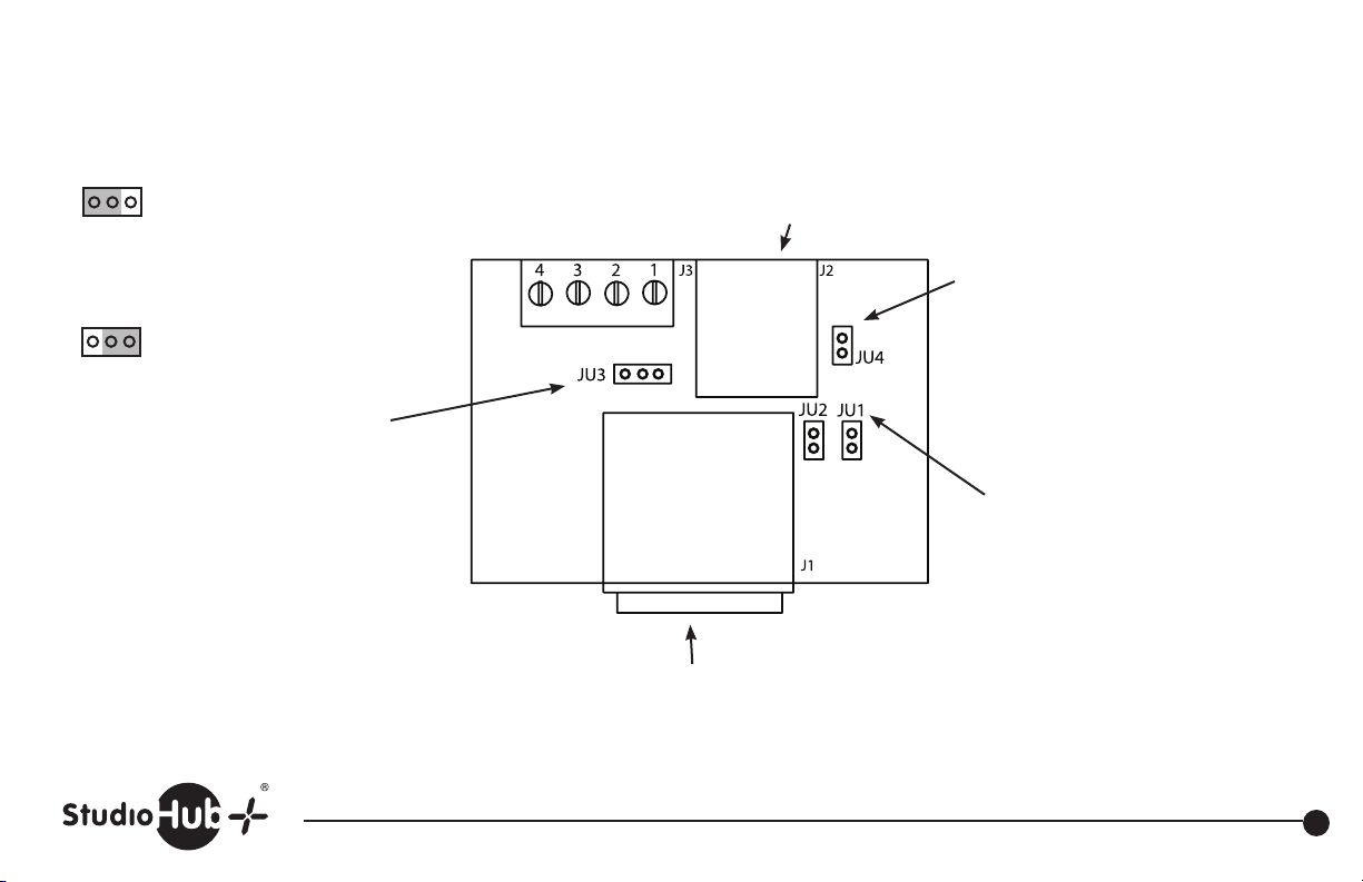
Install to connect external power
to light mic boom LED (5-15VDC)
via pins 3 & 4 on barrier
strip connector
JU3
Install to connect external power
to light mic boom LED (15VDC)
via pin 8 of RJ-45 when connected
to a standard StudioHub+ powered
Cube or Hub.
NOTE: Unused StudioHub+ RJ-45 pin 5 (CAT-5 wht/blu wire) is
connected to light mic boom LED when connected to ground
(DC voltage must be provided either via barrier strip pin 4 or
StudioHub+ pin 8. Program JU3 accordingly).
Gnd
+5-15VDC
(Mating 5-pin male in-line male
Gnd
Pull-to-Gnd to
light LED
5-Pin XLR
XLR connector included)
Created 2-05-14
JU4
Install to connect XLR pins to
XLR chassis ground
JU1, JU2
Install both jumpers to apply left
and right mic audio in parallel on
RJ-45 connector (StudioHub+
standard pins 1 & 2 for left, and
pins 3 & 6 for right). Remove both
jumpers to apply mic audio to left
channel only.
Part # SH-1XLRF
Made for Yellowtec Mic Arms
5
Pin StudioHub+ Single XLR 5Pin Female Panel
(856) 467-8000 • Fax (856) 467-3044 • www.studiohub.com
18
Page 20
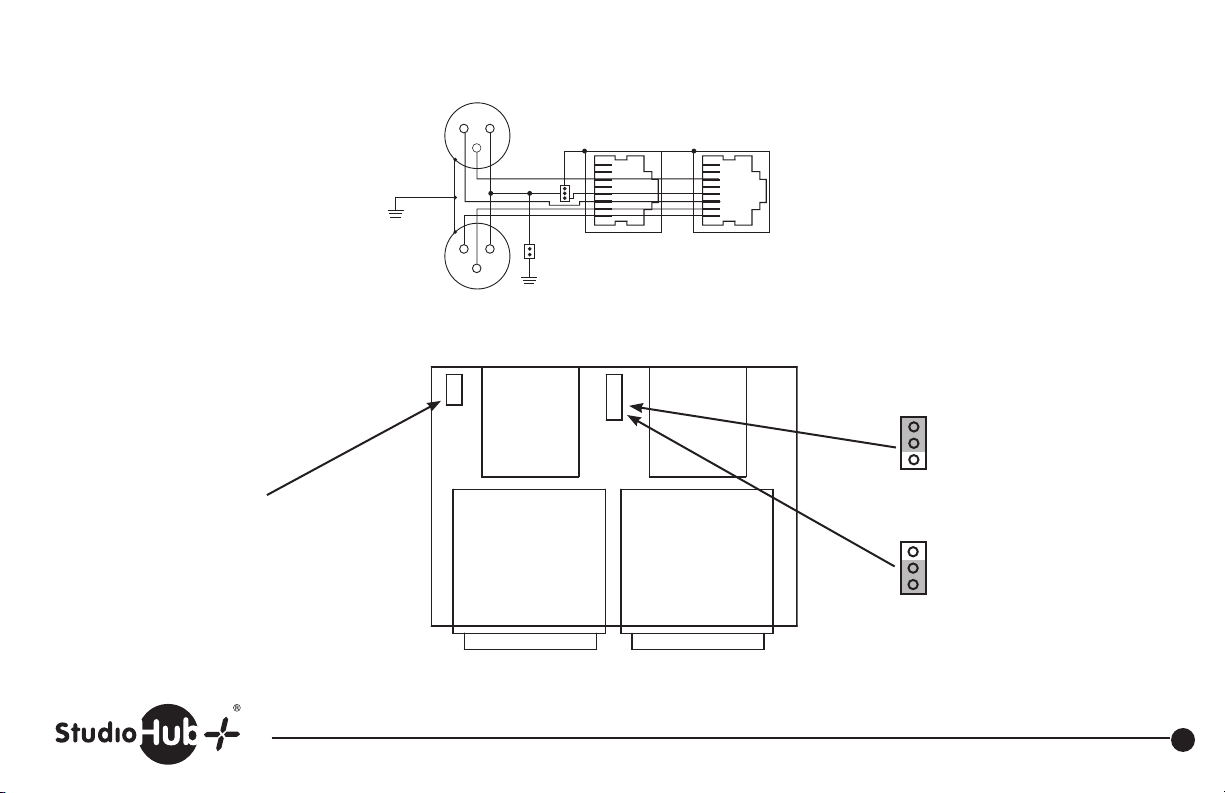
2
1
3
8
7
6
5
4
3
2
1
RJ-45 #1
8
7
6
5
4
3
2
1
2
1
3
Right
XLR
RJ-45 #2
8
7
6
5
4
3
2
1
2
1
3
2
1
3
8
7
6
5
4
3
2
1
Left
XLR
Right
XLR
CHASSIS
GROUND
RJ-45 #2
JU3
JU1
RJ-45 #1
JU2
JU4
CHASSIS
GROUND
CHASSIS
GROUND
JU3
JU1
JU4
JU2
CHASSIS
GROUND
CHASSIS
GROUND
CHASSIS
GROUND
Install JU1 to connect XLR(s)
pin 1 to chassis ground
Revised 4-21-10
For Stereo Operation: L & R XLR feed both RJ45’s in stereo.
2
1
3
2
1
3
CHASSIS
GROUND
JU2
JU1
8
7
6
5
4
3
2
1
RJ-45 #1
8
7
6
5
4
3
2
1
RJ-45 #2
CHASSIS
GROUND
Right
XLR
Left
XLR
RJ45-1 RJ45-2
JU2
JU1
STUDIOHUB+
J3
J1
J2
2F XLR TO RJ45
J4
JU2
Install to connect XLR(s) pin 1
to StudioHub+ RJ45 shield
JU2
Install to connect XLR(s) pin 1
to StudioHub+ RJ45
power ground (RJ-45 pin 4)
Left XLR Right XLR
(Obsolete Part) StudioHub+ Dual XLR Female Panel
(856) 467-8000 • Fax (856) 467-3044 • www.studiohub.com
19
Page 21
2
1
3
8
7
6
5
4
3
2
1
RJ-45 #1
8
7
6
5
4
3
2
1
2
1
3
Right
XLR
RJ-45 #2
8
7
6
5
4
3
2
1
2
1
3
2
1
3
8
7
6
5
4
3
2
1
Left
XLR
Right
XLR
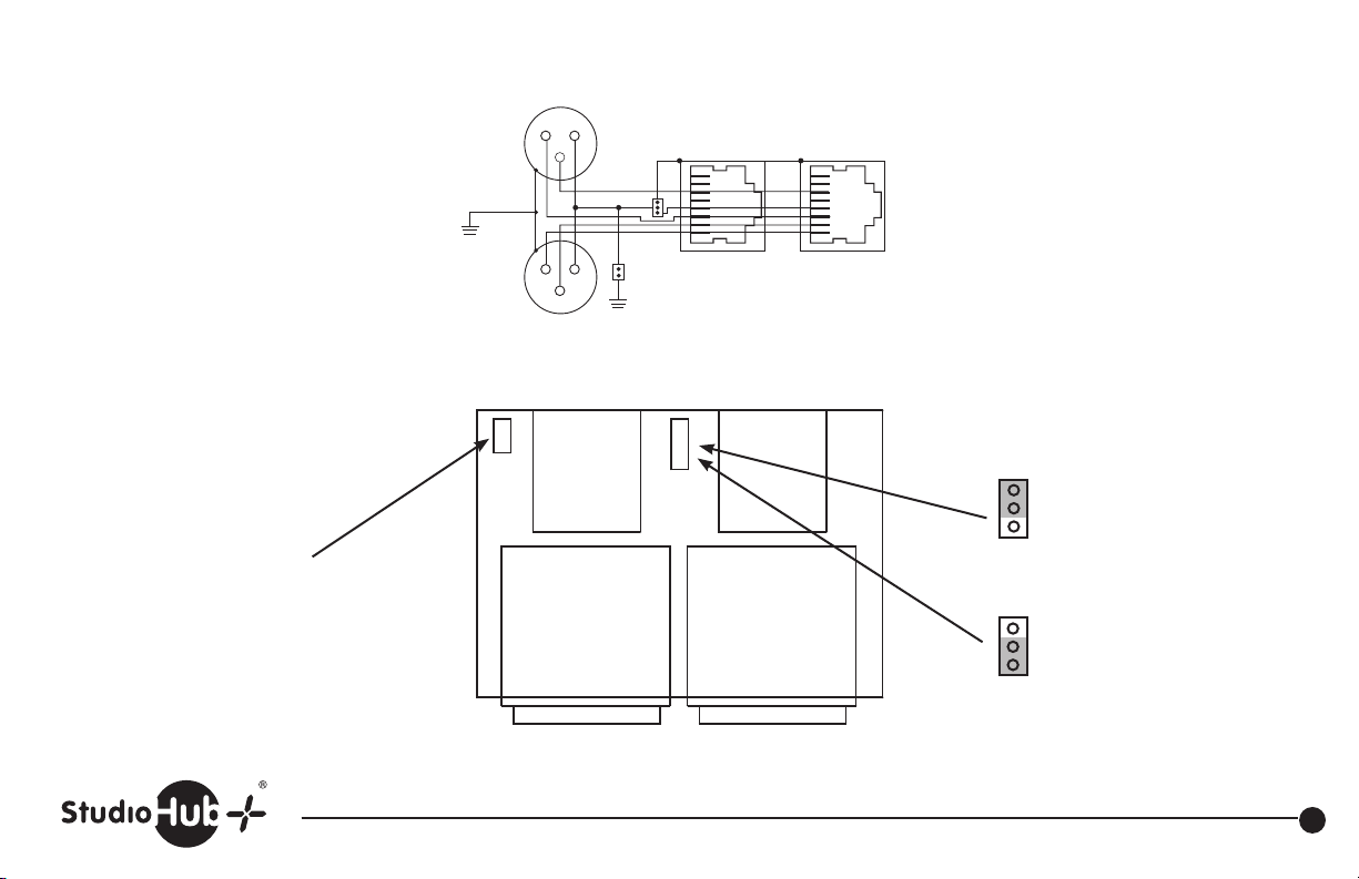
CHASSIS
GROUND
RJ-45 #2
JU3
JU1
RJ-45 #1
JU2
JU4
CHASSIS
GROUND
CHASSIS
GROUND
JU3
JU1
JU4
JU2
CHASSIS
GROUND
CHASSIS
GROUND
CHASSIS
GROUND
Install JU1 to connect XLR(s)
pin 1 to chassis ground
Revised 4-21-10
For Stereo Operation: L & R XLR feed both RJ45’s in stereo.
2
1
3
2
1
3
CHASSIS
GROUND
JU2
JU1
8
7
6
5
4
3
2
1
RJ-45 #1
8
7
6
5
4
3
2
1
RJ-45 #2
CHASSIS
GROUND
Right
XLR
Left
XLR
RJ45-1 RJ45-2
JU2
JU1
J1
J2
STUDIOHUB+
2M XLR TO RJ45
J3
J4
JU2
Install to connect XLR(s) pin 1
to StudioHub+ RJ45 shield
JU2
Install to connect XLR(s) pin 1
to StudioHub+ RJ45
power ground (RJ-45 pin 4)
Left XLR Right XLR
(Obsolete Part) StudioHub+ Dual XLR Male Panel
(856) 467-8000 • Fax (856) 467-3044 • www.studiohub.com
20
Page 22
Revised 4-21-10
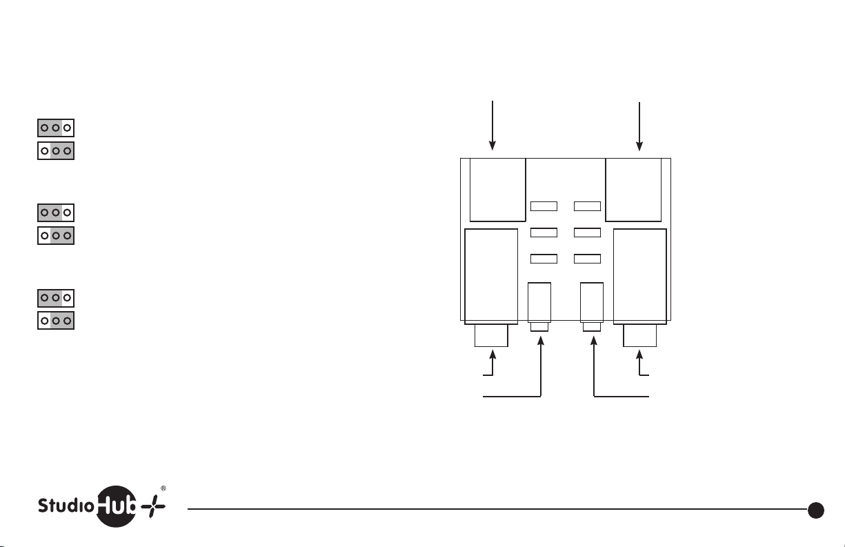
JU1 and JU2*
Install to tie StudioHub+ RJ45 right - connection to StudioHub+ shield.
Install to tie StudioHub+ RJ45 right - connection to StudioHub+ power ground.
JU3 and JU4*
Install to tie StudioHub+ RJ45 left - connection to StudioHub+ shield.
Install to tie StudioHub+ RJ45 left - connection to StudioHub+ power ground.
JU5 and JU6*
Install to tie 1/4” and mini TRS sleeve to StudioHub+ RJ45 shield.
Install to tie 1/4” and mini TRS sleeve to StudioHub+ RJ45 power ground.
*Improper use of JU1, JU2, JU3, JU4 may result in no output, excessive noise,
crosstalk, oscillation, or circuit failure.
Stereo unbalanced 1/4”
1/4” and mini TRS wiring
Tip = Left + StudioHub+ RJ45 connection
Ring = Right StudioHub+ RJ45 connection
Stereo unbalanced mini TRS
1/4” and mini TRS J3 and J5 are in
parallel. Use only one at a time.
Sleeve = See JU5 and JU6
Stereo unbalanced StudioHub+
RJ45. Signal to/from J3 and J5
STUDIOHUB+
UNBAL WORLD
GND
SHLD
J1
JU3
J5
SHLD
R-
JU1 JU2
L-
JU4
SLV
JU5
JU6
J4J3
GND
J6
1/4” and mini TRS J4 and J6 are in
parallel. Use only one at a time.
Stereo unbalanced StudioHub+
RJ45. Signal to/from J4 and J6
J2
Stereo unbalanced 1/4”
Stereo unbalanced mini TRS
Part # SH-1/4UNBAL StudioHub+ 1/4” & Mini TRS Panel (Unbalanced)
(856) 467-8000 • Fax (856) 467-3044 • www.studiohub.com
21
Page 23
2 Stereo StudioHub+ RJ45(s) in parallel
Revised 4-21-10
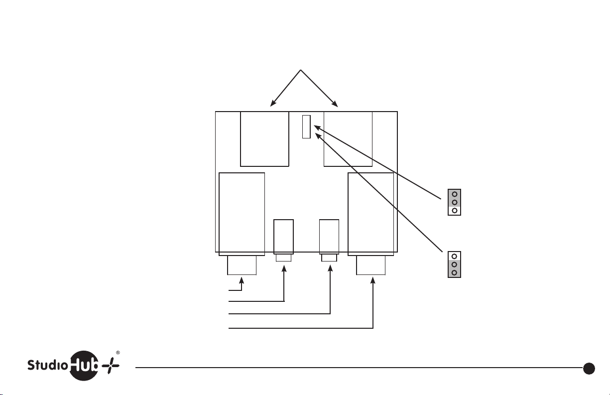
1/4” TRS & mini TRS, (J3/J4 and
J5/J6) are in parallel. Use only one
at a time.
Left balanced 1/4”TRS
Left balanced mini TRS
Right balanced mini TRS
Right balanced 1/4” TRS
1/4” mini TRS
(J3, J4, J5, J6) wiring
JU1
Tip = +
Ring = —
Sleeve = See JU1 pinouts below
J1
J5
1/4" AND MINI TRS
STUDIOHUB+
J6
J2
JU1 (upper pins)
Install to connect sleeve of
all 1/4” and mini jacks to
J4J3
StudioHub+ RJ45 shield
JU1 (lower pins)
Install to connect sleeve of
all 1/4” and mini jacks to
StudioHub+ RJ45
power ground
Part # SH-1/4BAL StudioHub+ 1/4” & Mini TRS Panel (Balanced)
(856) 467-8000 • Fax (856) 467-3044 • www.studiohub.com
22
Page 24
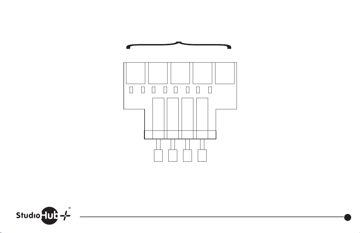
Jumpers JU1-JU8 tie +15volt and –15volt
from input RJ45(s) to the output RJ45 J5
Stereo StudioHub+ RJ45
input 1 input 2 input 3 input 4 output
Revised 01-02-13
Note:
This part obsolete as of
September 2012.
Replaced by active model
SH-4SWA
JU1 –15volts input 1
JU2 +15volts input 1
JU3 –15volts input 2
JU4 +15volts input 2
JU5 –15volts input 3
JU6 +15volts input 3
JU7 –15volts input 4
JU8 +15volts input 4
STUDIOHUB+
FOUR SELECT BOARD
J2J1
SW1
1 2 3 4
Input selects
J3
J4
J5
JU8JU7JU6JU5JU4JU3JU2JU1
(Obsolete Part) SH-4SW StudioHub+ 4 Source Switcher Panel
(856) 467-8000 • Fax (856) 467-3044 • www.studiohub.com
23
Page 25
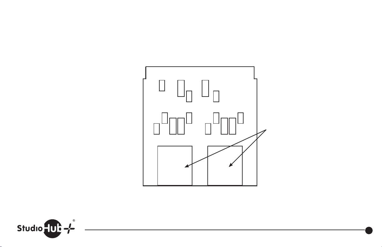
These internal buses and jumpers allow
+15volts, –15volts and shield to be connected
from the two studioHub+ RJ45(s) and the terminal block.
A circuit path requires at least two jumpers.
JU1 install to tie terminal block shield
to internal shield bus.
JU2 install to tie terminal block –15volts
to internal –15volt bus.
JU3 install to tie terminal block +15volts
to internal +15volt bus.
JU4 install to tie StudioHub+ RJ45 J2
+15volts to internal +15volt bus.
JU5 install to tie StudioHub+ RJ45 J2
–15volts to internal –15volt bus.
JU6 install to tie StudioHub+ RJ45 J3
+15volts to internal +15volt bus.
JU7 install to tie StudioHub+ RJ45 J3
–15volts to internal –15volt bus.
JU8 install to tie StudioHub+ RJ45 J2
shield to internal shield bus.
JU9 install to tie StudioHub+ RJ45 J3
shield to internal shield bus.
SHIELD
JU8
J2
JU1
+15V
Revised 4-21-10
J1
-15V
JU7
2 StudioHub+ RJ45 with
R6
pins below in parallel
1. Left + or AES/EBU+
-15V
-15V
JU5
R4
R2
JU3JU2
+15V
JU6JU4
+15V
SHIELDSHIELD
JU9
R5
R1
R3
2. Left – or AES/EBU–
3. Right +
6. Right –
4. Power Ground
STUDIOHUB+ BREAKOUT
J3
5. Future
Part # ADAPT-BO StudioHub+ Breakout Adapter
(856) 467-8000 • Fax (856) 467-3044 • www.studiohub.com
24
Page 26
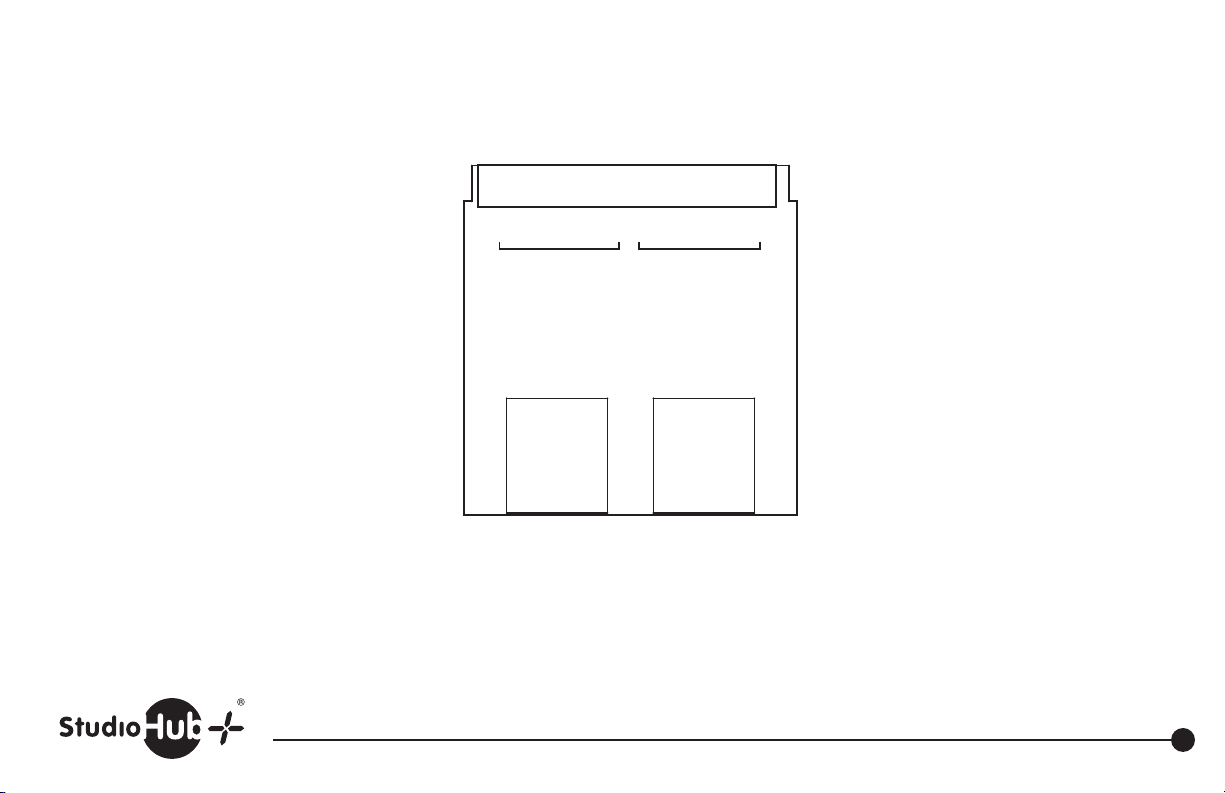
• • • • • • • • • • • • • • • •
Revised 3-30-11
RJ-45 ADAPT-GPI Pin Out for
Wheatstone BLade GPIO
RJ-45 Pin1- Audio Ground
RJ-45 Pin2- Logic 7 In/Out
RJ-45 Pin3- Logic 8 In/Out
RJ-45 Pin4- Logic 9 In/Out
RJ-45 Pin5- Logic 10 In/Out
RJ-45 Pin6- Logic 11 In/Out
RJ-45 Pin7- Logic 12 In/Out
RJ-45 Pin8- +5V Digital
J2
RJ-45 #2 (J2)
Pins 1-8
8 7 6 5 4 3 2 1 8 7 6 5 4 3 2 1
J1
J3
RJ-45 #1 (J1)
Pins 1-8
STUDIOHUB+ ADAPT-GPI
Part # ADAPT-GPI StudioHub+ Breakout Adapter
(856) 467-8000 • Fax (856) 467-3044 • www.studiohub.com
25
Page 27
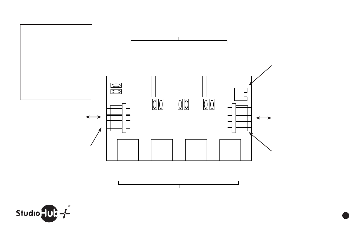
Revised 01-02-13
Ch. 1
Ch. 2
Ch. 3
Ch. 4
Notes:
Power is added to audio
connections and available
on the 4 output RJ-45’s (J1-J4).
The four stereo audio feeds
are kept seperated and
isolated.
Channels are independent,
isolated and independently
fused with self resetting
thermal fuses.
Power Supply
+/-15v In (or) Out
Max power provided 3 amps.
PS-EXTU Power Connector.
Allows P/N PS-EXTU wall-top
power supply to provide power.
Max power provided 3 amps.
J5
Powered-Side Feed to Devices
Aud Out
Pwr Out
R1
J1 J2 J3 J4
R2
+15V
-15V
G
n/c
Aud Out
Pwr Out
R3 R4 R5 R6 R7 R8
Aud Out
Pwr Out
Aud Out
Pwr Out
n/c
-15V
+15V
J7 J8 J9 J10
Ch. 1
Aud In
Ch. 2
Aud In
Ch. 3
Aud In
Non-Powered Input Side
G
Ch. 4
Aud In
PS-WW Cube Power Connector.
Allows P/N PS-WWCube or
PS-WWUCube desktop power
supply to provide power.
Max power provided 400 ma.
Power Supply
+/-15v In (or) Out.
Max power provided 3 amps.
J6
Loop-Thru Power Connector.
Power supply cable P/N 11516
(1 ft.) required. Contact the
factory to acquire at no charge
if needed.
Part # PS-CUBE StudioHub+ “DC-Link” Power Inserter
(856) 467-8000 • Fax (856) 467-3044 • www.studiohub.com
26
Page 28
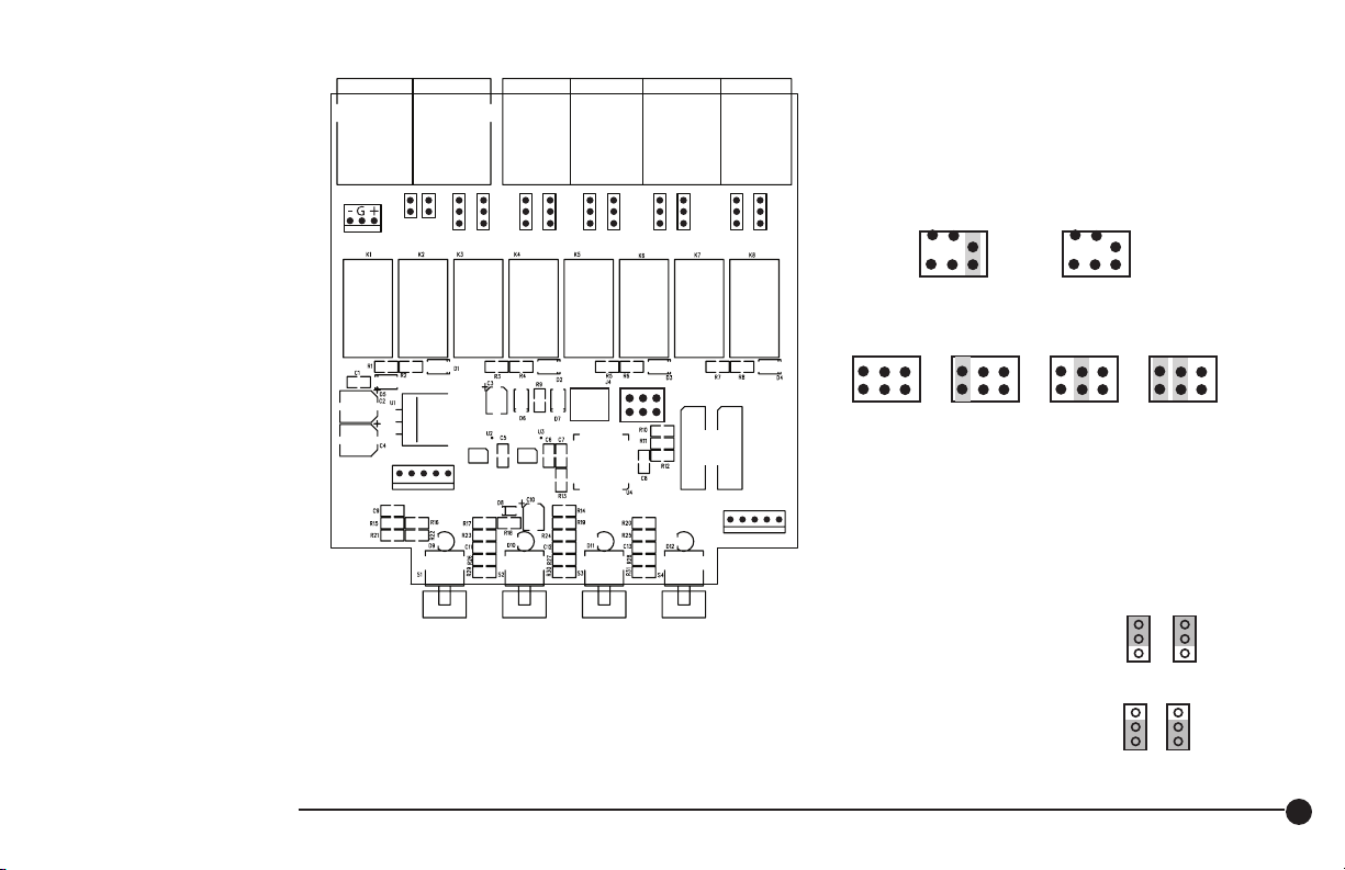
StudioHub+ 4 Source Switcher
The SH-4SHSS is an active
device and must be
powered via +/- 15VDC.
Power flows via StudioHub+
“DC-Link” if connected to any
Cat-5 cable with +/- 15VDC
active on Pins 7&8. Or, utilize
optional power supply is
part # PS-WWUSH.
Input selects will be
maintained in the event
of a power failure.
Input select switches may
be remote controlled via pins
on connector J4.
The unit is fully bidirectional
and may switch
4 inputs to 1 output or
1 input to 4 outputs
This circuit board is packaged
alone for single 1x4 use, or up to
4 maybe interconnected for up
to a 1x16 switching application.
I/O B I/O A I/O 4
(I/O A & I/O B are in parallel)
J3
JU2
PWR
J8
JU1
1234G
LOGIC OUTPUT
JU6JU5JU4JU5
1 2 3 4
Special Purpose Logic Output J8
(Special PROM required)
1 +5VDC
2 NC
4 Pull to Ground #2
5 GND
3 Pull to Ground #1
I/O 3 I/O 2 I/O 1
JU7
PGM
ONLY
J5
J6
Daisy
Chain
Part #
Revised 07-22-15
(Note - There are older versions of this product.
See www.studiohub.com/legacyproducts)
J5 – Programing
(Note- power must be cycled for mode change)
JU12JU11 JU10JU9JU8
J7
1234G
Install C for
momentary
operation
(default)
a b c
Supports
1 SH-4SHSS
board
a b c
4 switches
total
Supports
2 SH-4SHSS
a b c a b c a b c
8 switches
Shielding Jumpers:
boards
total
Remove C for
holding
operation
a b c
Supports
3 SH-4SHSS
boards
12 switches
total
Supports
4 SH-4SHSS
boards
16 switches
total
JU1 – insert to connect power ground to chassis ground
JU2 – insert to connect power ground to shield
Mono/Stereo Jumpers JU5-JU12:
Stereo
To make inputs stereo set
both jumpers to upper position
To make inputs mono set
Mono
both jumpers to lower position
SH-4SWSS StudioHub+ 4 Source Switcher Panel
(856) 467-8000 • Fax (856) 467-3044 • www.studiohub.com
27
Page 29
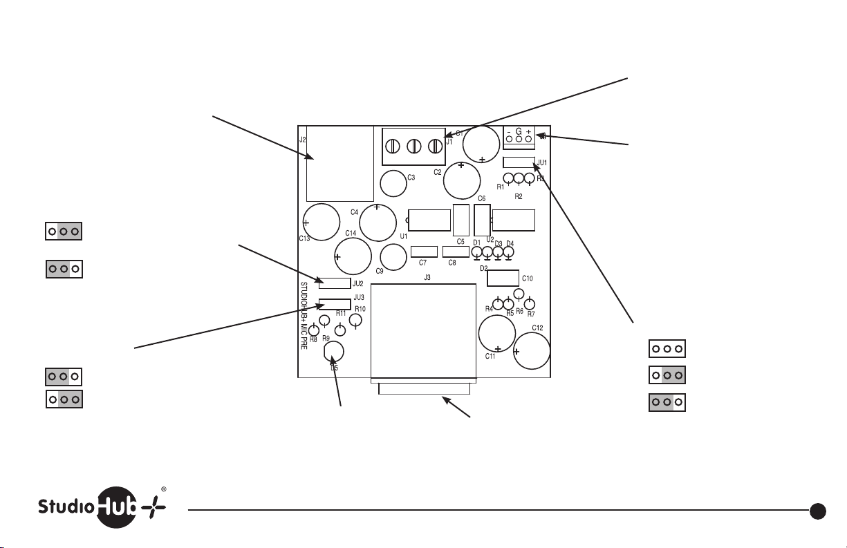
3 2 1
StudioHub+ RJ45 Output and power in.
Output appears on both left (1 & 2) and
right (3 &6) connector pins
JU2
XLR pin 1 select
Install to connect XLR pin 1
to RJ-45 shield.
Install to connect XLR pin 1
to power ground & J1 pin 3
Revised 05-06-09
Power Ground
Output +
Output –
Output Audio
Direct power input
+/- 15 volts DC
JU3
Phantom Power
Off
On (+15 Volts)
Power LED
XLR Microphone input
Part # SH-MIC StudioHub+ Mic Preamp Panel
(856) 467-8000 • Fax (856) 467-3044 • www.studiohub.com
JU1 Gain
26dB
46dB
66dB
28
Page 30
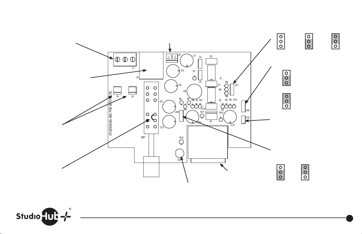
Revised 11-06-13
Output audio provided on
barrier strip
StudioHub+ RJ45 Output and power in.
Output appears on both left (1 & 2)
and right (3 &6) connector pins
JU1 & JU2
Isolated dry N. O.
switch contacts
Install jumper to
defeat push to talk
(on/off switching of mic output)
Shield Ground
Output +
Output –
Push to talk
Note: Specify on order
Push On/Push Off or
momentary operation
Direct power input
+/- 15 volts DC
JU1 Gain
26dB 46dB 66dB
JU2 XLR pin 1 select
Install to connect
XLR pin 1 to
shield ground
Install to connect
XLR pin 1 to
power ground
JU4
Install to connect XLR pin 1
to chassis ground
JU3
Phantom Power
Off On (+15 volts)
XLR Microphone input
Switch “pushed” LED
Part # SH-MICPTT StudioHub+ Mic Preamp w/PTT Panel
(856) 467-8000 • Fax (856) 467-3044 • www.studiohub.com
29
Page 31
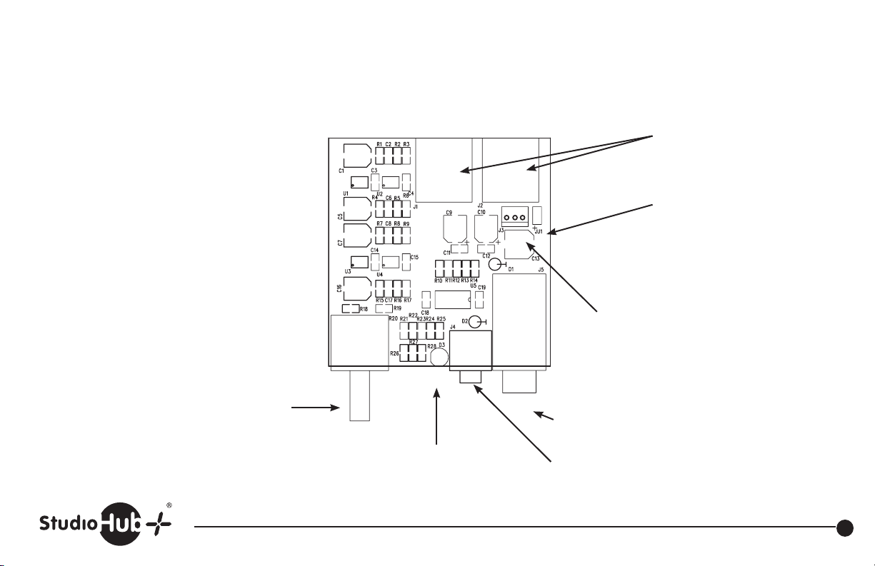
Revised 11-28-12
2 StudioHub+ RJ45
input and power on
connectors in parallel
Headphone level
Blue Power LED
G
+
-
JU1
Install to connect shield
ground to power ground
Direct power input
+/- 15 volts DC
1/4” headphone jack
1/8” (mini) headphone jack
Part # SH-HPB StudioHub+ Headphone Amplifier Panel
(856) 467-8000 • Fax (856) 467-3044 • www.studiohub.com
30
Page 32
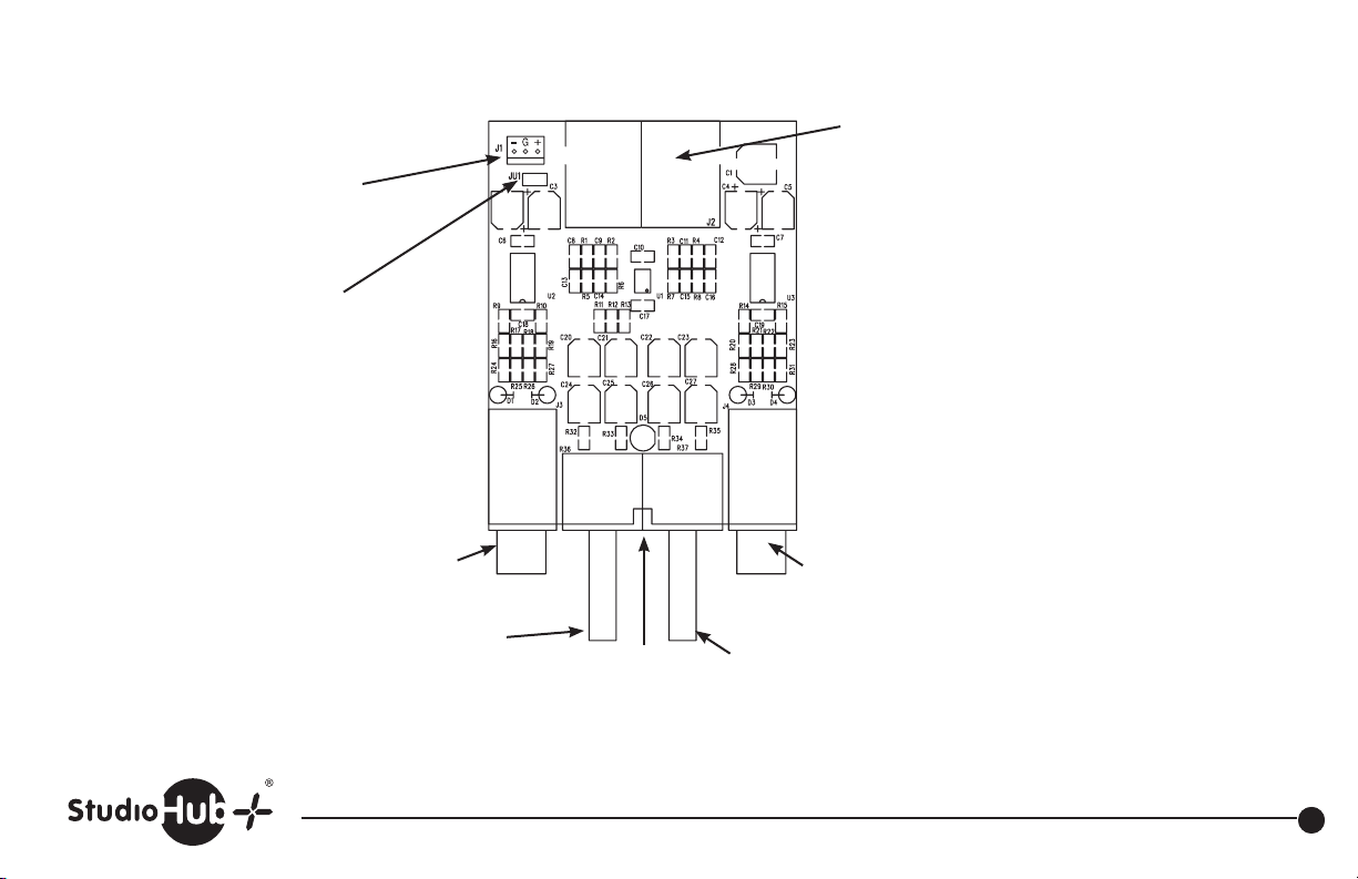
J1
Direct power input
+/- 15 volts DC
JU1
Install to connect shield
ground to power ground
1/4” headphone jack
HP AMP #1
Revised 5-08-13
J2 Two StudioHub+ RJ45
input and power on
connectors in parallel
StudioHub+ Heaphone Amplifier
Dual Output Version
RJ-45 input jacks remain in
parallel (there is only 1 input.)
Each output is isolated and
at full power (with separate
output amplifier chips.)
Current consumption is 100ma.
All other specifications are
identical to single (SH-HP) model.
1/4” headphone jack
HP AMP #2
Headphone level
HP AMP #1
Power
LED
Headphone level
HP AMP #2
Part # SH-HPDUAL StudioHub+ Headphone Amplifier Dual Plate
(856) 467-8000 • Fax (856) 467-3044 • www.studiohub.com
31
Page 33
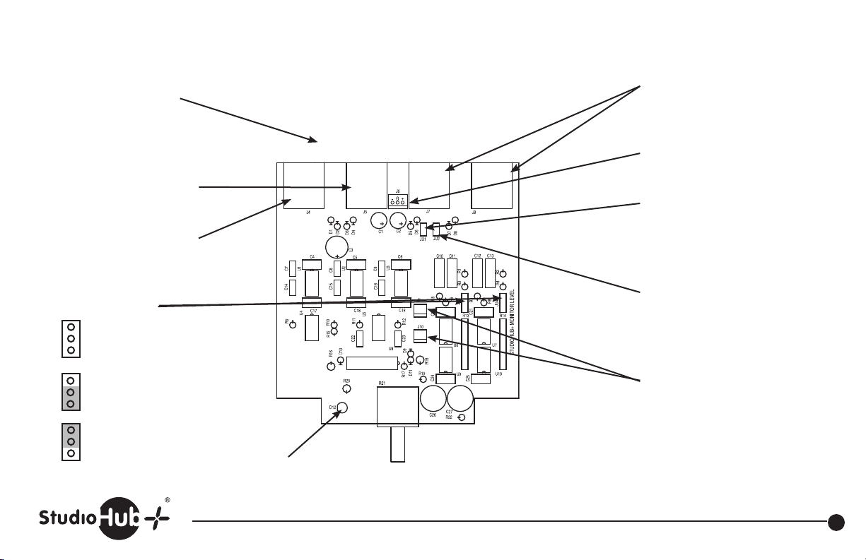
Revised 4-21-10
Audio and power input
provided on barrier strip
Stereo StudioHub+ RJ45(s)
stereo output and power in
Stereo StudioHub+ RJ45(s)
mono output and power in
JU3, JU4 gain select
Unity -
no jumper
+10dB
+20dB
2 StudioHub+ RJ45
input and power in
connectors in parallel
Direct power input
+/- 15 volts DC
JU1
Install to connect shield ground
and power ground
JU2
Install to connect shield ground
and chassis ground
JU9, JU10
2 mute control connectors in
parallel. Short the pins on either
connector together for mute
Power LED
Level
Part # SH-LEVEL StudioHub+ Monitor Level Control Panel
(856) 467-8000 • Fax (856) 467-3044 • www.studiohub.com
32
Page 34
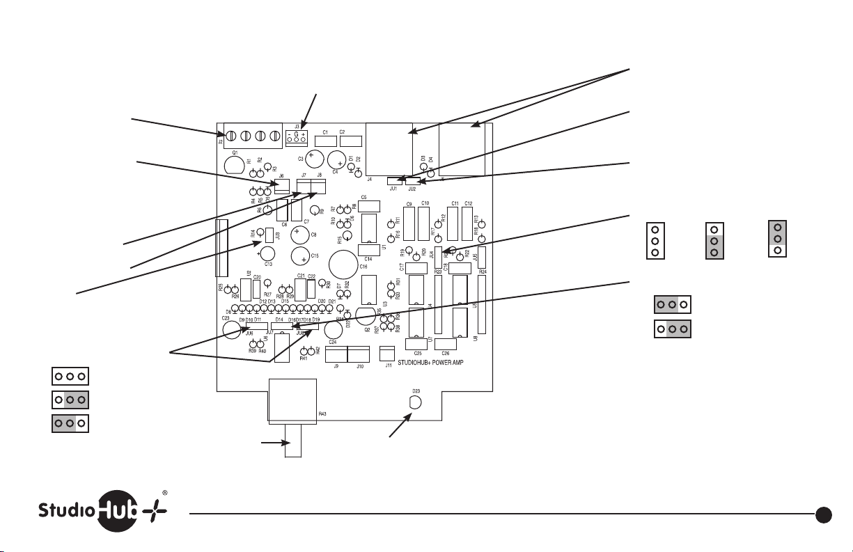
Revised 4-21-10
Speaker Outputs
JU6 Mute
Short these pins
together to mute
J7 Left speaker
J8 Right speaker
JU3
Install for stereo operation
JU6 and JU8 Power limit
Full power
Medium power
Low power
L
e
f
t
Level control
R
G
G
i
r
r
g
o
o
h
u
u
t
n
n
d
d
Direct power in
+/- 15 volts DC
2 StudioHub+ RJ45 Input and
power in connectors in parallel
JU1
Install to connect shield
ground to power ground
JU2
Install to connect shield
ground to chassis ground
JU4, JU5 Gain Straps
Unity +10dB +20dB
Gain
JU7 Mono - Stereo jumper
Stereo operation
Mono operation
Left output is a mix of left and
right inputs. Right output is muted
Signal
Present
LED
StudioHub+ Monitor Amp Panel
Part # SH-AMP w/o Speaker
Part # SH-AMPSPKR w/Speaker
(856) 467-8000 • Fax (856) 467-3044 • www.studiohub.com
33
Page 35
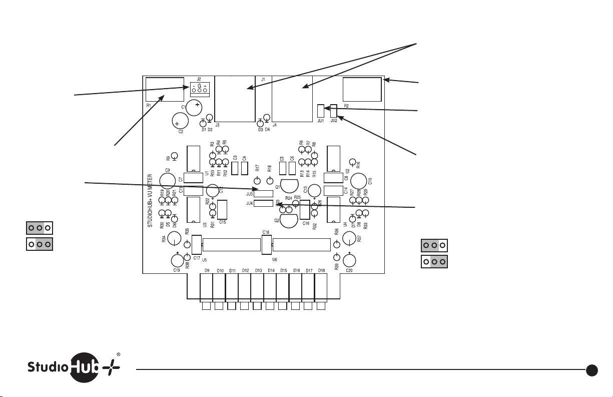
Direct power input
+/- 15 volts DC
Top row/right row LED
level control
JU3
Top row/left row
LED input select.
Left input
Right input
Revised 4-21-10
2 StudioHub+ RJ45
Input and power in connectors
in parallel
Bottom row/right row LED
level control
JU1
Install to connect shield
ground to power ground
JU2
Install to connect shield
ground to chassis ground
JU4
Bottom row/right row LED
input select
Right input
Left input
Part # SH-VUV Dual VU Meter Panel (Vertical)
Part # SH-VUH Dual VU Meter Panel (Horizontal)
•
(856) 467-8000
Fax (856) 467-3044 • www.studiohub.com
34
Page 36
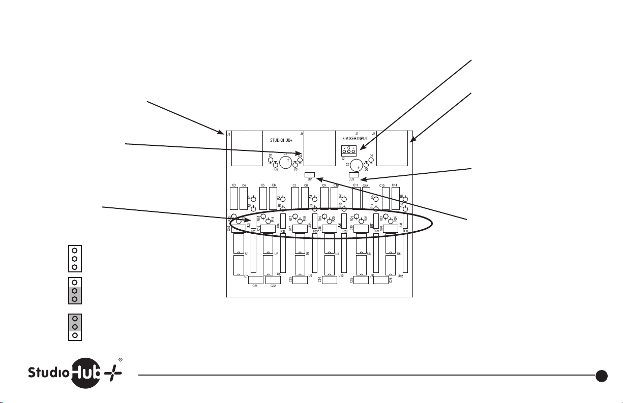
Direct power input
+/- 15 volts DC
Revised 4-21-10
StudioHub+ RJ45
input 1 and power in
Stereo StudioHub+ RJ45
input 2 and power in
Gain Straps (pre-fader)
JU3, JU4 Input 1
JU5, JU6 Input 2
JU7, JU8 Input 3
No jumper for unity gain
normal for +4dBu applications
+10dB gain
+20dB gain
StudioHub+ RJ45
Input 3 and power in
JU2
Install to connect shield
ground to chassis ground
JU1
Install to connect shield
ground to power ground
Part # SH-MIXER StudioHub+ 3 Mixer Panel (Input Board)
(856) 467-8000 • Fax (856) 467-3044 • www.studiohub.com
35
Page 37
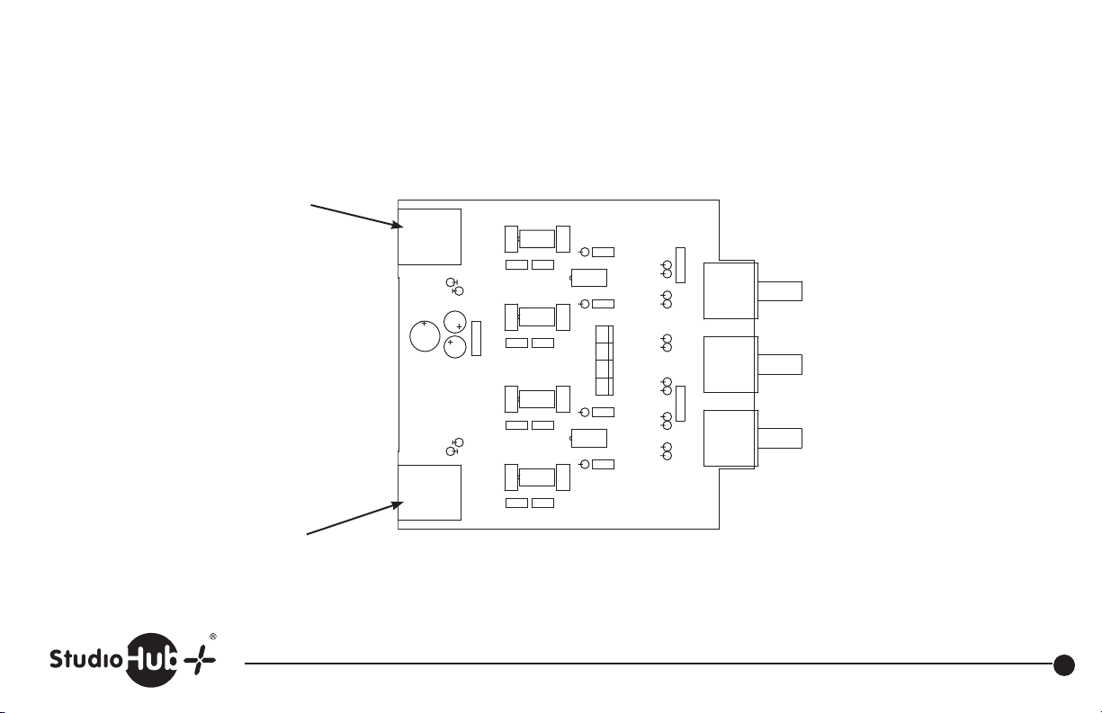
ASSEMBLY STAND ALONE 12103A
ASSEMBLY STUDIOHUB+ 12102A
StudioHub+ RJ45 main output.
Mix of inputs 1, 2 and 3.
Also power in
Revised 4-21-10
StudioHub+ RJ45mix minus output.
Mix of inputs 1 and 2 only.
Also power in
C7C6
U4
J3
D4
J1
C3
C1
C2
D1
J2
C11
D3
J4
U3
C10
C5C4
U2
C9
D2
U1
C8
R4
C23
C15
U6
C22
R3
C18 C19
C17
R2
U5
R1
C16
J7
J5 J6 J8
C21
C20
C14
C13
C12
J10
R16
R15
R14
R13
R19
R12
R11
R10
R9
R18
R8
R7
J9
R6
R5
R17
STUDIOHUB+ 3 MIXER OUTPUT
Input 3
mix level
Input 2
mix level
Input 1
mix level
Part # SH-MIXER StudioHub+ 3 Mixer Panel (Output Board)
(856) 467-8000 • Fax (856) 467-3044 • www.studiohub.com
36
Page 38
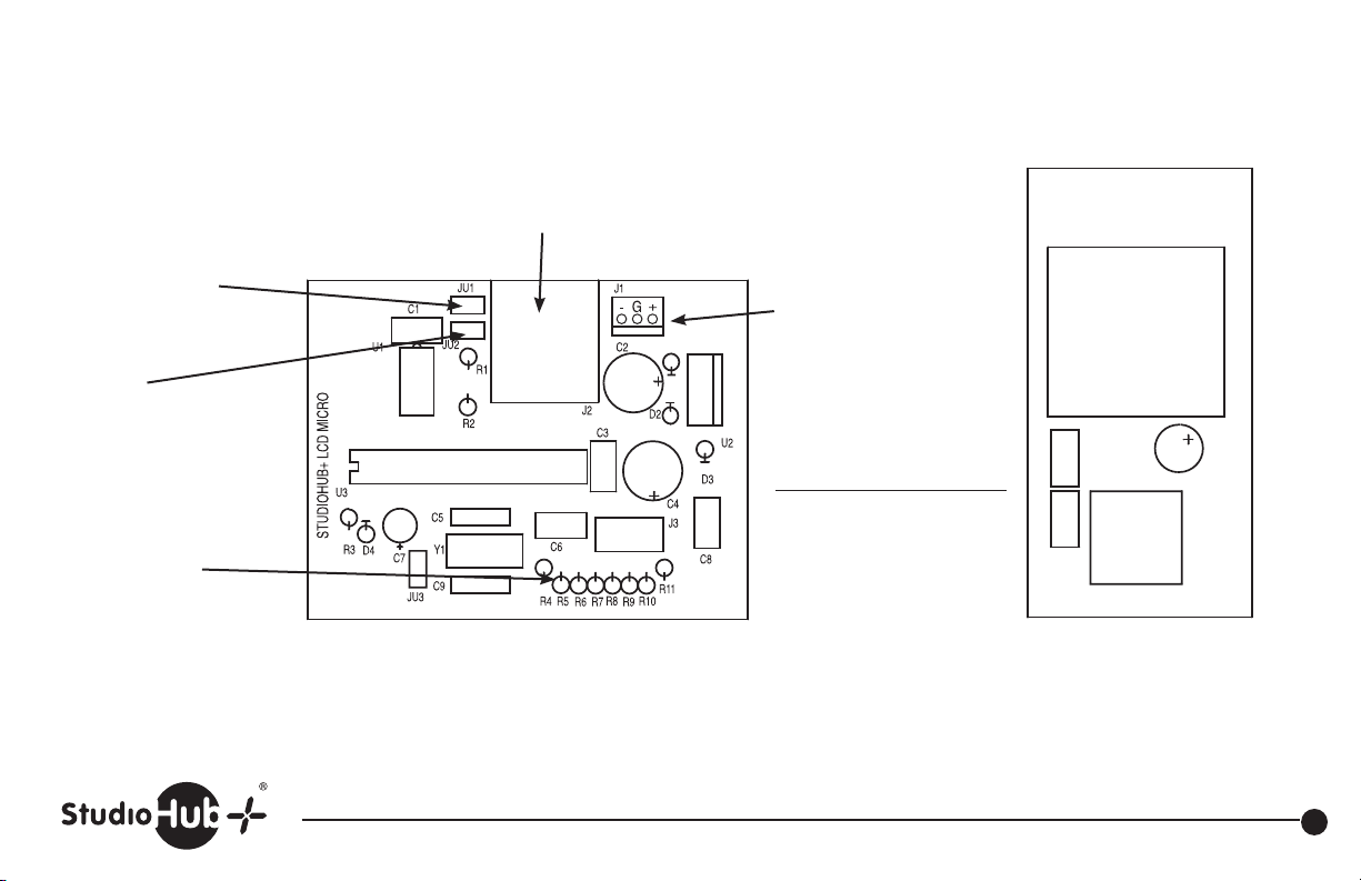
Revised 4-21-10
JU1
Install to connect
shield ground to
chassis ground
JU2
Install to connect
shield ground to
power ground
JU3
Install/remove to
reverse direction of
rotary encoder
StudioHub+ RJ45 data input,
data output and power in.
Direct power input
+/- 15 volts DC
RJ-45 Pin-Outs Function
1 TxD+
2 TxD3 RxD+
6 RxD8 +15 volt
4 ground
This board must be used in conjunction
with the LCD display board.
Part # SH-LCDV StudioHub+ Vertical LCD Controller Panel
Part # SH-LCDH StudioHub+ Horizintal LCD Controller Panel
STUDIOHUB+
LCD DISPLAY BOARD
Interface Pin-Outs
S1
C2
C3
C1
S2
This board to be used in conjunction
with the LCD micro board
(856) 467-8000 • Fax (856) 467-3044 • www.studiohub.com
37
Page 39
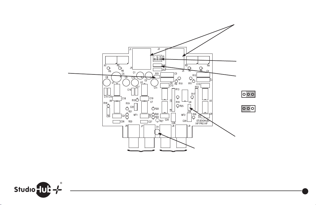
Revised 4-21-10
Audio in/out and power input
provided on RJ-45’s
Right Level
Let Level
Right Level
Let Level
JU3
Install to connect shield
ground to chassis ground
Balanced
Output
and
Power In
Balanced
Input
and
Power In
Power LED
Left Right
Left Right
IHF Unbalanced Input IHF Unbalanced Output
Part # SH-DUALMATCH StudioHub+ In/Out Balanced Panel
(856) 467-8000 • Fax (856) 467-3044 • www.studiohub.com
J3
Direct power input
+/- 15 volts DC
JU1 and JU2
(install both the same)
Board power
from J5
Board power
from J4
JU4
Install to connect shield
ground to power ground
38
Page 40
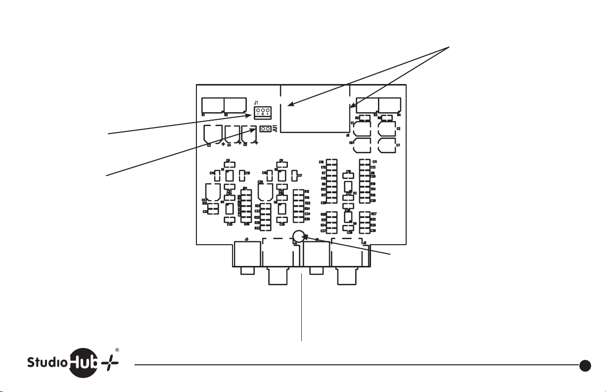
Created 9-28-11
J1
Direct power input
+/- 15 volts DC
JU1
Install to connect shield
ground to chassis ground
Right Level
Let Level
1/8”
(mini) TRS
Phone IHF
Unbalanced
Input
Balanced
Input
and
Power
Left & Right
RCA
IHF
Unbalanced
Input
Balanced
Output
and
Power
1/8”
(mini) TRS
Phone IHF
Unbalanced
Output
Let Level
Left & Right
RCA
IHF
Unbalanced
Output
Right Level
Power LED
Audio in and out and StudioHub+
“DC-Link” +/- 15VDC power
provided on RJ-45’s
Part # SH-MATCHPANEL StudioHub+ In/Out Balanced Panel
(856) 467-8000 • Fax (856) 467-3044 • www.studiohub.com
39
Page 41

Warranty
Radio Systems, Inc., warrants this equipment to be free from defects in materials and workmanship for a period of one (1) year.
This warranty extends to first users of the product and future owners who purchase the product within the warranty period.
The terms of this warranty are null and void if this product is stored or operated in an environment not conducive to electronic equipment, or shows
signs of misuse or modifications which affect the proper functioning of the product. This warranty does not apply to damage caused by fire, smoke,
flood, lightning, or acts of nature and physical abuse.
Radio Systems, Inc., and its associated companies, authorized distributors, and personnel are not liable for loss of revenues or other damages, or
effects to the broadcast signal quality or coverage which may result from the from the improper functioning of this product.
Repair Policy
Technical assistance is available at any time, at no charge, by phone or correspondence.
During the warranty period, there will be no charge for parts or service made to units which show no sign of misuse by customer or lightning caused
damage. The customer is responsible for the cost of shipping their unit back to Radio Systems for repair.
During the warranty period, shipment of small parts and assemblies may also be made at a charge to the user. Emergency shipments of replacement
parts and circuits will be made at the user’s request for an extra shipping and service charge. Chargeable services will be made COD or on Net-30 day
terms to users with established accounts.
During the warranty period, full credit or return of COD charges (less any service and expedited shipping charges) will be made to users who return the
defective parts or circuits within 30 days, if the damage is covered under the terms of the warranty.
Return Instructions
Contact Radio Systems for a return authorization number.
Pack all items carefully and ship prepaid, via UPS insured, to: Radio Systems, Inc.
Attn: R.A. # __________
601 Heron Drive
Logan Township, New Jersey 08085-1741
Enclose a note which includes your name, company, phone number, the serial number, return address (no box numbers),
and a complete description of the problem.
(856) 467-8000 • Fax (856) 467-3044 • www.studiohub.com
Page 42

Revised 10-30-2015
601 Heron Drive • Logan Township, New Jersey 08085 • (856) 467-8000 • Fax (856) 467-3044
www.studiohub.com • www.radiosystems.com
 Loading...