

Page 1

© All rights reserved.
This manual may not be copied in any media or form without the written consent of the manufacturer.
Page 2

Page 3

Preface
i
Table of Contents
Chapter 1
Introduction
Package Contents . . . . . . . . . . . . . . . . . . . . . . . . . . . . . . . . . . . . . . . . . . . . . . .2
Features . . . . . . . . . . . . . . . . . . . . . . . . . . . . . . . . . . . . . . . . . . . . . . . . . . . . . . .2
Components . . . . . . . . . . . . . . . . . . . . . . . . . . . . . . . . . . . . . . . . . . . . . . . . . . . .3
Front View. . . . . . . . . . . . . . . . . . . . . . . . . . . . . . . . . . . . . . . . . . . . . . . . . . . .3
Top View . . . . . . . . . . . . . . . . . . . . . . . . . . . . . . . . . . . . . . . . . . . . . . . . . . . . .4
Rear View . . . . . . . . . . . . . . . . . . . . . . . . . . . . . . . . . . . . . . . . . . . . . . . . . . . .5
Remote Control . . . . . . . . . . . . . . . . . . . . . . . . . . . . . . . . . . . . . . . . . . . . . . . .6
Chapter 2
Connections
Before Setting Up . . . . . . . . . . . . . . . . . . . . . . . . . . . . . . . . . . . . . . . . . . . . . . .7
Connections . . . . . . . . . . . . . . . . . . . . . . . . . . . . . . . . . . . . . . . . . . . . . . . . . . . .7
Power . . . . . . . . . . . . . . . . . . . . . . . . . . . . . . . . . . . . . . . . . . . . . . . . . . . . . . . .7
Device Connections. . . . . . . . . . . . . . . . . . . . . . . . . . . . . . . . . . . . . . . . . . . . .8
Wired Remote Control. . . . . . . . . . . . . . . . . . . . . . . . . . . . . . . . . . . . . . . . . .11
+12VDC Outlet . . . . . . . . . . . . . . . . . . . . . . . . . . . . . . . . . . . . . . . . . . . . . . .11
Turning On/Off . . . . . . . . . . . . . . . . . . . . . . . . . . . . . . . . . . . . . . . . . . . . . . .12
Turning Off . . . . . . . . . . . . . . . . . . . . . . . . . . . . . . . . . . . . . . . . . . . . . . . . . .13
Chapter 3
Operation
Operating the Control Panel and Remote Control . . . . . . . . . . . . . . . . . . .14
Zoom and Focus . . . . . . . . . . . . . . . . . . . . . . . . . . . . . . . . . . . . . . . . . . . . . .14
Power . . . . . . . . . . . . . . . . . . . . . . . . . . . . . . . . . . . . . . . . . . . . . . . . . . . . . . .14
Input. . . . . . . . . . . . . . . . . . . . . . . . . . . . . . . . . . . . . . . . . . . . . . . . . . . . . . . .15
Menu . . . . . . . . . . . . . . . . . . . . . . . . . . . . . . . . . . . . . . . . . . . . . . . . . . . . . . .15
Color Temperature. . . . . . . . . . . . . . . . . . . . . . . . . . . . . . . . . . . . . . . . . . . . .15
Navigation Buttons . . . . . . . . . . . . . . . . . . . . . . . . . . . . . . . . . . . . . . . . . . . .16
The Remote Control . . . . . . . . . . . . . . . . . . . . . . . . . . . . . . . . . . . . . . . . . . .16
Setting Up the Projector . . . . . . . . . . . . . . . . . . . . . . . . . . . . . . . . . . . . . . . .17
Page 4

Preface
ii
Chapter 4
OSD Menus
About the OSD Menus . . . . . . . . . . . . . . . . . . . . . . . . . . . . . . . . . . . . . . . . . 18
Main Menu . . . . . . . . . . . . . . . . . . . . . . . . . . . . . . . . . . . . . . . . . . . . . . . . . . 18
Input Signals . . . . . . . . . . . . . . . . . . . . . . . . . . . . . . . . . . . . . . . . . . . . . . . . 19
Picture (Video Only) . . . . . . . . . . . . . . . . . . . . . . . . . . . . . . . . . . . . . . . . . . 19
Advanced . . . . . . . . . . . . . . . . . . . . . . . . . . . . . . . . . . . . . . . . . . . . . . . . . . . 22
Video System . . . . . . . . . . . . . . . . . . . . . . . . . . . . . . . . . . . . . . . . . . . . . . . . 23
FLI De-interlacing . . . . . . . . . . . . . . . . . . . . . . . . . . . . . . . . . . . . . . . . . . . . 23
RS232 Baud Rate . . . . . . . . . . . . . . . . . . . . . . . . . . . . . . . . . . . . . . . . . . . . . 23
Geometry . . . . . . . . . . . . . . . . . . . . . . . . . . . . . . . . . . . . . . . . . . . . . . . . . . . 26
Aspect Ratio. . . . . . . . . . . . . . . . . . . . . . . . . . . . . . . . . . . . . . . . . . . . . . . . . 27
Language . . . . . . . . . . . . . . . . . . . . . . . . . . . . . . . . . . . . . . . . . . . . . . . . . . . 28
Factory Default . . . . . . . . . . . . . . . . . . . . . . . . . . . . . . . . . . . . . . . . . . . . . . 28
Appendix A
Specifications
Product Specifications . . . . . . . . . . . . . . . . . . . . . . . . . . . . . . . . . . . . . . . . . 29
Appendix B
Maintenance
Maintenance . . . . . . . . . . . . . . . . . . . . . . . . . . . . . . . . . . . . . . . . . . . . . . . . . 30
Lamp Maintenance. . . . . . . . . . . . . . . . . . . . . . . . . . . . . . . . . . . . . . . . . . . . 30
Cleaning the Air Filters . . . . . . . . . . . . . . . . . . . . . . . . . . . . . . . . . . . . . . . . 33
Troubleshooting . . . . . . . . . . . . . . . . . . . . . . . . . . . . . . . . . . . . . . . . . . . . . . 34
Appendix C
The Gamma Manager Utility
About the Gamma Manager Utility . . . . . . . . . . . . . . . . . . . . . . . . . . . . . . 35
Required Hardware and Software . . . . . . . . . . . . . . . . . . . . . . . . . . . . . . . . 35
Connecting the Projector to the PC . . . . . . . . . . . . . . . . . . . . . . . . . . . . . . 36
Connecting the Projector to a PC. . . . . . . . . . . . . . . . . . . . . . . . . . . . . . . . . 36
Installing the Software . . . . . . . . . . . . . . . . . . . . . . . . . . . . . . . . . . . . . . . . . 37
Uninstalling the Software. . . . . . . . . . . . . . . . . . . . . . . . . . . . . . . . . . . . . . . 39
Using the Gamma Manager Utility . . . . . . . . . . . . . . . . . . . . . . . . . . . . . . . 40
Appendix D
Throw Ratio
About the Throw Ratio . . . . . . . . . . . . . . . . . . . . . . . . . . . . . . . . . . . . . . . . . 47
Page 5

Preface
iii
Desktop Installation. . . . . . . . . . . . . . . . . . . . . . . . . . . . . . . . . . . . . . . . . . . .47
Ceiling Mount Installation. . . . . . . . . . . . . . . . . . . . . . . . . . . . . . . . . . . . . . .50
Appendix E
RS-232 communication
RS-232C communication. . . . . . . . . . . . . . . . . . . . . . . . . . . . . . . . . . . . . . . .53
Communications setting . . . . . . . . . . . . . . . . . . . . . . . . . . . . . . . . . . . . . . . .53
Computer (Windows) - HyPer Terminal . . . . . . . . . . . . . . . . . . . . . . . . . . . .53
Command Or Read command . . . . . . . . . . . . . . . . . . . . . . . . . . . . . . . . . . . .53
Computer (Windows) - RS232ControlAP.exe . . . . . . . . . . . . . . . . . . . . . . .54
Command data chart . . . . . . . . . . . . . . . . . . . . . . . . . . . . . . . . . . . . . . . . . . .55
Page 6

Preface
About this manual
This manual is designed for use with the PREMIERE 50HD DLP Projector. Information in this document has been carefully checked for accuracy; however, no guarantee is given to the correctness of the contents. The information in this document is
subject to change without notice.
Copyright
© Copyright 2003
This document contains proprietary information protected by copyright. All rights are
reserved. No part of this manual may be reproduced by any mechanical, electronic
or other means, in any form, without prior written permission of the manufacturer.
Trademarks
All trademarks and registered trademarks are the property of their respective owners.
FCC COMPLIANCE
This device complies with Part 15 of the FCC Rules. Operation is subject to the following two conditions:
(1) This device may not cause harmful interference.
(2) This device must accept any interference received, including interference that
may cause undesired operation.
Federal Communications Commission (FCC) Statement
This equipment has been tested and found to comply with the limits for a Class B
digital device, pursuant to part 15 of the FCC Rules. These limits are designed to
provide reasonable protection against harmful interference in a residential installation. This equipment generates, uses and can radiate radio frequency energy and, if
not installed and used in accordance with the instructions, may cause harmful interference to radio communications. However, there is no guarantee that interference
will not occur in a particular installation. If this equipment does cause harmful interference to radio or television reception, which can be determined by turning the
equipment off and on, the user is encouraged to try to correct the interference by one
or more of the following measures:
• Reorient or relocate the receiving antenna.
• Increase the separation between the equipment and the receiver.
• Connect the equipment to an outlet on a circuit different from that to which the
receiver is connected.
• Consult the dealer or an experienced radio/TV technician for help.
Page 7

Preface
NOTICES
Warning! To meet FCC requirements, a shielded power cord is
required in order to prevent interference. It is essential that only the
supplied power cord be used. Use only shielded cables to connect
I/O devices to this equipment. You are cautioned that changes or
modifications not approved by the party responsible for compliance
could void your authority to operate the equipment.
Warning! The projector cooling fan continues to run for approximately two minutes after the projector is turned off using the Power
button on the control panel or remote control. Never turn off the
projector using the power switch on the projector while the lamp is
lit. This can damage the lamp or power supply.
Warning! High brightness light source. Do not stare into the beam
of light, or view directly. Do not allow children to stare directly into
the beam of light.
Warning! To reduce the risk of fire or electric shock, do not expose
this product to rain or moisture.
Caution!
For minimal servicing and to maintain high image quality, we recommend that you use the projector in an environment that is smoke
and dust free. When used in areas where there is a lot of smoke or
dust, the filter and lens should be cleaned often to lengthen the service life of the projector.
Warning! The ventilation slots, lamp, and objects next to them may
get extremely hot during operation. Do not touch these areas until
they have sufficiently cooled down.
Warning! When replacing the lamp, turn off the power switch and
disconnect the input power. Allow the lamp to cool at least 15 minutes prior to opening the lamp door.
Page 8

Preface
Warning! Be careful when removing the lamp. In the event of a lamp
rupture there may be small fragments of glass in the lamp housing
and the projector. Clean out the fragments as much as possible taking care not to touch the fragments. Alternately, you can contact
Technical Support to have the projector serviced.
Page 9

Precautions
When using the projector, refer to the following instructions :
• Read and follow all instructions and warnings provided.
• Save these instructions for future use.
• When servicing or replacement parts are required, ensure work is done by a
qualified technician.
• Do not use this unit near water or in a rainy/moist environment, or near heat
sources such as radiators, stoves, or space heaters.
• Use supplied cables only.
• Never insert any objects through ventilation holes.
• The projector power cable is equipped with a three-prong plug for grounding.
Do not alter the plug and defeat this safety feature. If your outlet does not
accommodate a three-prong grounding type plug, contact an electrician to
replace it.
• Only mount the projector on a tabletop or ceiling as recommended by the
manufacturer.
• Do not place the projector on an unstable cart or stand.
• Allow at least 0.3 foot (10 cm) space between the ventilation slots and the
nearest object or wall.
• When the ventilation slots are obstructed, the projector lamp automatically
turns off as a safety precaution. When this happens, the over temperature
alarm LED will light. Remove the obstruction and push the power button again
to return the projector to normal operating condition.
Any electrical equipment is hazardous if handled improperly. Ensure that you follow
the preceding safety instructions to avoid harm to yourself and damage to the unit.
Note: The projector has an over temperature warning LED on the control
panel. If the projector overheats because of a dirty filter or other problem,
the LED will flash, and the projector lamp will turn off, after which a 2minute cooling off period occurs. If, after correcting the over temperature
condition and restarting the projector, the projector still doesn't function
properly, contact technical support to arrange for service.
Page 10
INTRODUCTION
Chapter 1
Introduction
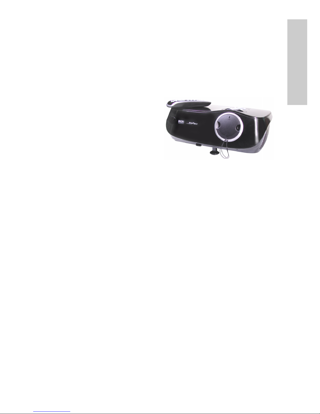
Congratulations on selecting the Premiere 50HD DLP Projector.
The Premiere 50HD DLP is the first
mainstream projector to offer Silicon
Optix AnyPlace™ technology, which
provides flexibility in projector placement while displaying a high-definition
image.
The projector is equipped with a full
set of I/O connectors, enabling you to
attach a wide variety of input devices
including Composite Video, S-Video,
Digital Video Interface (DVI), Computer VGA, and Component Video.
The control panel and remote control enable you to easily set up functions such as
input source, aspect, gamma correction, and color temperature. The keystone feature provides maximum flexibility in projector placement while still providing a flat
image.
The menu driven OSD (On-Screen Display) provides a suite of functions that enable
you to set such items such as the source input device, gamma, brightness, contrast,
clock, and phase. The RS-232 port enables easy upgrades to ensure that the projector firmware is always up-to-date.
The Silicon Optix image processor is incorporated in the design with its unique AnyPlace™ technology, which adjusts for the vertical and horizontal projection angles to
the screen, allowing users to place the projector anywhere in the room and still display a perfect image. This eliminates the need for room remodelling, and enables the
projector to naturally blend into a room. In addition to AnyPlace placement flexibility,
the Premiere 50HD DLP projector delivers superior keystone and scaling image
quality.
The Premiere 50HD DLP Projector is supported by a standard two-year limited warranty.
Page 11

Chapter 1 – Introduction
2
INTRODUCTION
Package Contents
Open the package and ensure that you have the following items:
•Power Cord
• Remote control and two AAA alkaline batteries
• Warranty Card
•Cables
– Remote wired cable
– RCA cable for composite video
– VGA cable
• User's manual
• Quick Guide
• CD installation kit
If anything is missing or appears damaged, contact your dealer immediately. Do not
discard the packing materials in the event you need to ship the unit for service.
Features
The Premiere 50HD DLP Projector comes with the following advanced features:
• 1280 x 720 native resolution
• Super high contrast ratio (1700 & above), providing enhanced image depth
• Brightness control allows for excellent film viewing in different ambient lighting
conditions
• TI DLP™ Technology Premiere 50HD DMD providing superior image quality
• 5X speed color wheel with 6 color segments provides outstanding color reproduction
• Native 16:9 aspect ratio
• Faroudja video de-interlacing chip incorporates enhanced 3:2 pull down and
DCDi, providing you with crystal clear, high-resolution picture performance
• Anyplace™ scaling technology provides the ability to perform simultaneous
horizontal and vertical keystone (Diagonal-keystone-correction™). This technology enables the projector to be positioned almost anywhere in a room
• Wide-angle optical system design and Anyplace™ technology perform all
scaling functions, real-time geometry processing, and distortion correction
• Professional quality video conversion eliminates the image distortion that
occurs when standard television content (4:3 aspect ratio) is displayed on a
16:9 HDTV front projection display system
• User friendly backlit remote control and control panel
Page 12
Chapter 1 – Introduction
3
INTRODUCTION
Components
Front View
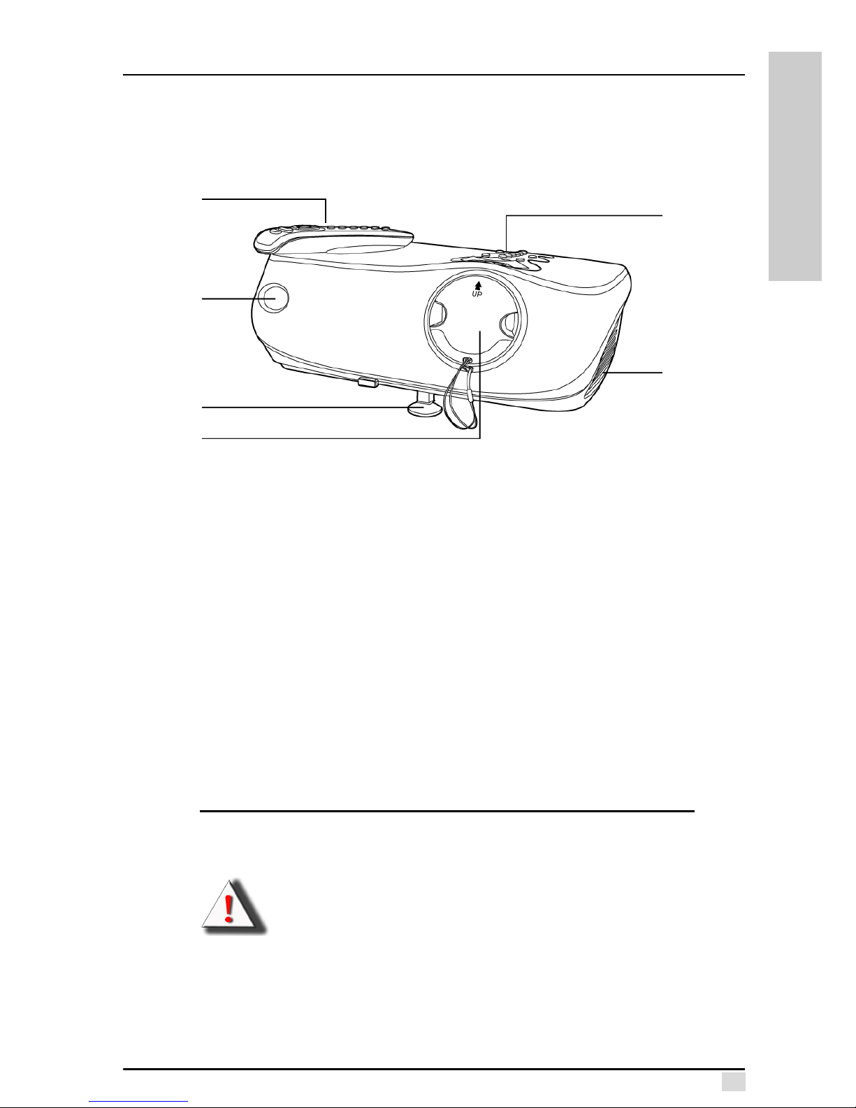
Remote Control: Enables you to control the projector. There are infrared sensors on
the front and rear of the projector allowing you to control the color temperature, input
device, gamma correction, OSD menu items, and turn the projector on and off. You
can also connect the remote control to the Wire Remote Control jack on the back
panel. See "Wired Remote Control" on page 11.
Control Panel: The control panel enables you to adjust the focus and zoom of the
projector lens, set the input device, gamma, and color temperature, access the OSD
menus, and turn the projector on and off.
Remote Control Sensor: Point the remote control at this sensor to operate the projector with the remote control. There is another sensor at the rear of the projector.
Lens Cap: The lens cap protects the projector lens when the projector is not in use.
Ventilation: The projector has a strong fan to keep the lamp from becoming too hot.
Adjustment Peg: The adjusment peg enables you to adjust the image height.
Note: Ensure that the ventilation slots have enough space around them
for proper air flow.
Warning!
Because the projector lamp becomes extremely hot, air coming
from the ventilation slots can be uncomfortably hot.
Remote
Control
Ventilation
Lens Cap
Remote
Control
Sensor
Control
Panel
Adjustment
Peg
Page 13

Chapter 1 – Introduction
4
INTRODUCTION
Top View
Focus: Turn this dial to focus the projected image on the screen.
Zoom: Turn this dial to adjust the size of the projected image on the screen.
Over Temperature Alarm LED: This LED flashes when the projector lamp becomes
too hot.
Warning! When this LED flashes, the lamp will shut off and the cooling fans will continue to run for approximately two minutes. Check
the air intakes and filter to make sure they are not clogged or
blocked. Refer to "Cleaning The Air Filters" on page 34 for further
information about cleaning the Air Filters. Refer to "Turning Off" on
page 13 for proper power down procedures.
Power on/ Standby: Press this button to put the projector into or bring it out of
standby mode.
Note: The Power button does not turn all power off. The power switch at
the rear of the projector turns it off. See "Turning Off" on page 13 for
proper power down procedures.
Input: Press this button to select the input source (for example S-Video or DVI).
Color Temperature: Enables you to set the image color temperature. You can set it
to Native, 5500, 6500, or 9300 K, or User Mode for fine adjustment.
Menu: Press this button to enter the OSD menus.
Menu Controls: These buttons enable you to navigate the menus. The up and down
arrows scroll up and down through the menus, while the left and right arrows scroll
left and right. Press the Enter button to enter a value, setting, or to go into a sub-
menu. Press the left button to exit the OSD menus or submenus.
Gamma: Enables you to set the gamma correction. Default setting is gamma 2.2.
Gamma curves for all input sources can be set using the gamma user mode. Users
can use the Gamma Manager utility to adjust or create gamma curves as desired.
The Gamma Manager can be found on the bundled CD installation kit or downloaded
from our Web site. Refer to appendix C for more information about this utility.
Focus
Zoom
Input
Menu
OSD Menu Controls
Power on/ Standby
Gamma Correction
Over Temperature Alarm LED
Color Temperature
Page 14
Chapter 1 – Introduction
5
INTRODUCTION
Rear View
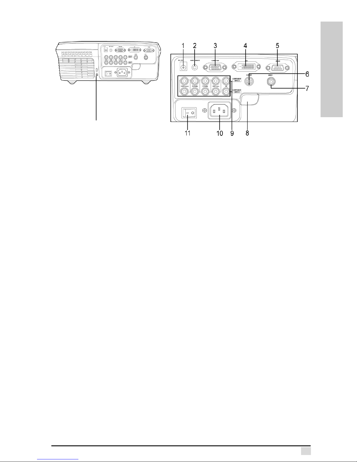
Ventilation: This fan provides ventilation to the lamp. Ensure that you do not
obstruct this opening.
Kensington Lock: Connect a Kensington MicroSaver Security System to this aperture. Refer to the information that came with the system for instructions on how to
use it to secure the projector from theft.
Back Panel I/O: The back panel I/O provides input and control connections. The following describes each control or I/O port.
1. +12VDC Outlet: Power outlet for an external device such as an automatic
screen. This output is energized when the projector is turned on. Before using
this feature, ensure that the polarity of the external device matches the projector and the current rating is less than 200 mA to avoid damage to the projector.
2. Wired Remote: Connecting the remote control directly to the projector allows
the remote control to work over greater distances and without interference
from external sources such as fluorescent lighting.
3. Computer/Input 1: Connect a computer’s VGA output to this RGB 15-pin Dsub port to project the computer display.
4. DVI-D/Input 1: Connect a Digital Video Interface device to this port.
5. RS-232: Connect a serial cable to this 9-pin D-sub port and your computer to
perform firmware upgrades or to control the projector using RS232 commands
(See Appendix E).
6. S-Video/Input 4: Connect an S-Video source to this 4-pin mini-DIN port.
7. Composite Video/Input 4: Connect a standard RCA video cable to this port.
8. Rear Remote Infrared Sensor: Point the remote control at this sensor to control the projector.
9. Component / Input - 2&3: Attach component device cables to these RCA
ports. Component Video will provide the best image quality.
10.AC Power Socket: Connect the power cable to this socket.
11. Power Switch: Turns the power to the projector on and off. Note that you
must press the Power button on the top control panel to put the projector in
operating mode. Do not set this switch to off if the projector lamp is on. Always
place the projector into standby mode prior to setting this switch to off.
Ventilation Back panel I/O and
controls
Kensington
lock aperture
Back panel I/O and controls
Page 15

Chapter 1 – Introduction
6
INTRODUCTION
Remote Control
Power: Press this button to put the projector into or bring it out of standby mode.
Note: The Power button does not turn all power off. The power switch at
the rear of the projector turns it off. See "Turning Off" on page 13 for
more information.
Menu: Press this button to enter the OSD menus.
Menu Controls: These buttons enable you to navigate the menus. The up and down
arrows scroll up and down through menus, while the left and right arrows scroll left
and right. Press the Enter button to enter a value or setting.
Color Temperature: Enables you to set the image color temperature. You can set it
to Native, 5500, 6500, 9300 K or User Mode.
Input: Press this button to select the type of input signal connected to the projector
– Input 1 – computer or DVI
– Input 2&3 – component 1&2
– Input 4 – S-Video/composite Video
Gamma: Enables you to set the gamma correction. Default setting is gamma 2.2.
There is gamma user mode for users to define their own gamma curve for all input
sources. Users can use the Gamma Manager utility to adjust or create gamma
curves as desired. The Gamma Manager can be found on the bundled CD installation kit or downloaded from our Web site. Refer to appendix C for more information
about this utility.
This concludes this chapter. The next chapter explains how to connect the projector
to power and different types of input devices.
Menu
Menu
Controls
Input 1 (Computer/DVI)
Input 2 (Component 1)
Input 3 (Component 2)
Color Temperature
Input 4 (S/
OSD
Exit
Power on/ Standby
Composite -Video)
Gamma Correction
Page 16
CONNECTIONS
Chapter 2
Connections
Before Setting Up
The Premiere 50HD DLP Projector is extremely flexible when considering installation
locations. The keystone feature enables you to place the projector at an angle to the
screen and digitally corrects the distortion of the skewed image. You can configure
the image for rear, mirror, or ceiling mounted projection.
When positioning the projector, follow these tips and precautions:
• Place the projector on a stable surface. When mounting the projector on the
ceiling, ensure that it is securely fastened to the ceiling mount.
• Ensure that the projector has enough space around it to provide proper ventilation.
• Place the projector so that the power cable and device cables are out of the
way of foot traffic.
• Ensure that the infrared ports are unobstructed to ensure that you have maximum range with the remote control.
Connections
This section covers connecting devices to the I/O sockets and ports on the rear
panel. See “Rear View” on page 5 for the location of the ports.
Power
The projector’s power supply is a universal input (100-240VAC)
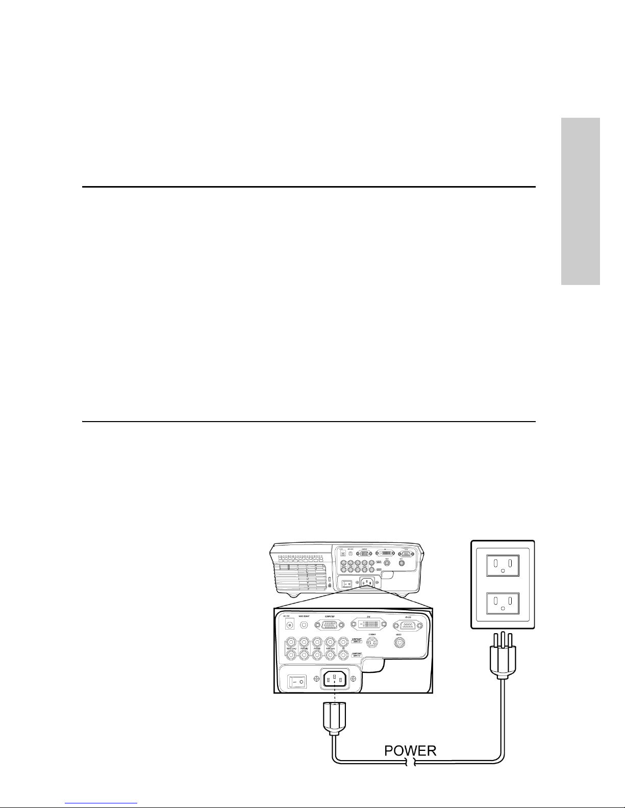
Connecting Power
Connect the power cable to
the AC socket on the rear
panel.
AC socket
Page 17
Chapter 2 – Connections
8
CONNECTIONS
Device Connections
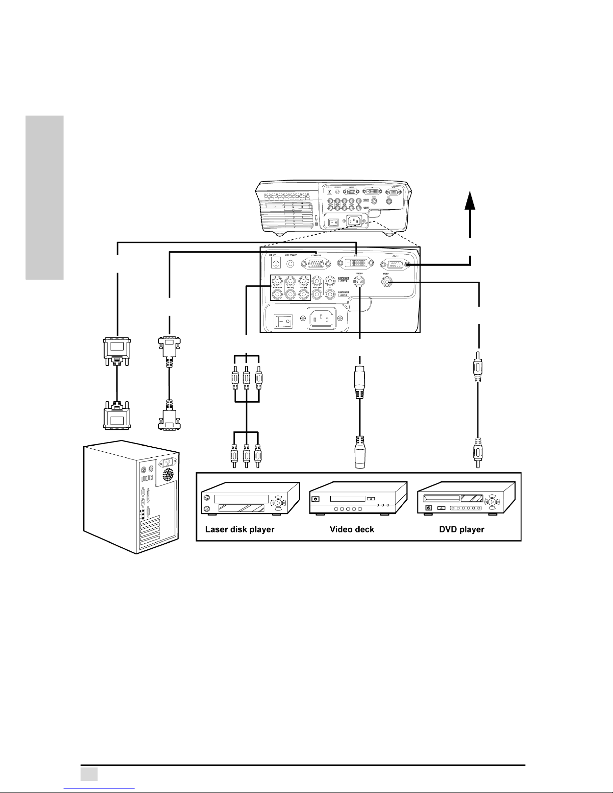
The following section describes device connections. The projector supports connections to a wide variety of multimedia output devices. Refer to the illustration on the
next page for device connection locations.
Computer Graphics Compatibility
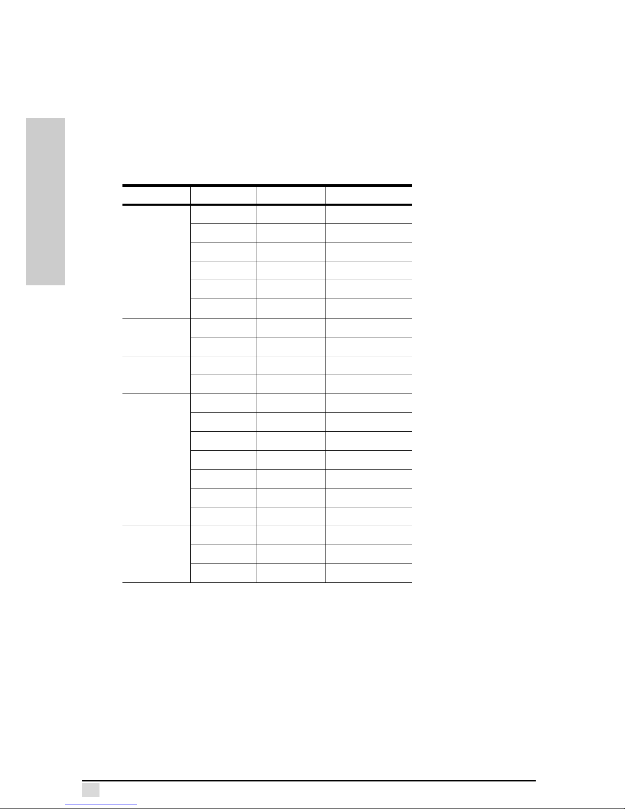
The following table lists the supported input signals and corresponding resolutions.
Keystone Input Resolution V. FREQ (Hz)
Standard
NTSC 720 x 480 —
PAL 720 x 580 —
VGA 640 x 480 60/72/75/85
SVGA 800 x 600 56/60/72/75/85
XGA 1024 x 768 60/70/75/85
SXGA 1280 x 1024 60
Letterbox
NTSC 720 x 480 —
PAL 720 x 580 —
Virtual Wide
NTSC 720 x 480 —
PAL 720 x 580 —
Anamorphic
NTSC 720 x 480 —
PAL 720 x 580 —
VGA 640 x 480 60/72/75/85
SVGA 800 x 600 56/60/72/75/85
XGA 1024 x 768 60/70/75/85
720P 1280 x 720 —
1080i 1920 x 1080 —
Pixel to Pixel
VGA 640 x 480 60/72/75/85
SVGA 800 x 600 56/60/72/75/85
XGA 1024 x 768 60/70/75/85
Page 18

Chapter 2 – Connections
9
CONNECTIONS
Computer/Input 1
The computer port enables you to connect your computer to the projector using a
standard 15-pin D-sub VGA cable.
DVI input/Input 1
The projector supports connection to a DVI (Digital Visual Interface), which enables
you to connect any device with DVI-D (Digital Only) output.
RS-232
The standard RS-232 port enables you to connect the projector to a PC and upgrade
the projector firmware through a PC or control the projector using RS232 commands. See Appendix E for more information about RS232 controls.
Note: The firmware upgrade is located on the CD that came bundled with
the projector. Contact your dealer for information on future upgrades.
Component/ Input 2 & 3
The projector supports two component video devices (Input 2&3). Component video
is typically transmitted in either YPbPr/YCbCr or RGB (Red/Green/Blue) formats.
Component video connections provide the best picture quality and are preferable to
S-Video and Composite Video connections.
Note: The PbPc/YCbCr color model is used for encoding video. Pb/Cb is
the luminosity of the black and white signal. Pb/Cb and Pr/Cr are color
difference signals. Pb/Cb is blue minus Y (B-Y), and Pr/Cr is red minus Y
(R-Y). The Premiere 50HD DLP Projector provides three standard RCA
phono plugs (x 2) to support YPbPc/YCbCr component video output.
S-Video/Input 4
Connect a DVD, VCR, or DTV decoder source device with the S-Video cable to this
socket. S-video separates pictures into chrominance and luminance signals providing a high quality image that is preferable to a composite video connection.
Composite Video/Input 4
Connect a DVD, VCR, or DTV decoder source device to this socket.
Page 19
Chapter 2 – Connections
10
CONNECTIONS
DVI
Computer
Component
S-Video
To computer
serial port.
RS-232
Composite
Video
Page 20
Chapter 2 – Connections
11
CONNECTIONS
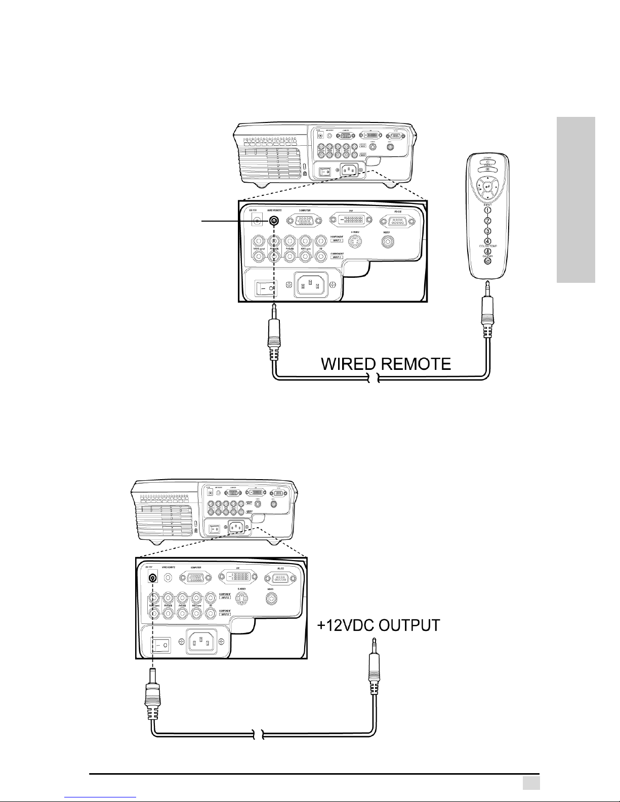
Wired Remote Control
The wired remote control jack enables you to connect the remote control to the projector using the included cable. When using the wire remote control feature, you do
not have to be in the line of sight of the IR sensors to operate the projector. Also, the
remote control is powered by the projector which saves battery power.
+12VDC Outlet
The +12VDC Outlet jack enables you to trigger an external device when the projector power is turned on. The maximum output current is 200mA. Please use an adaptor plug with "+" polarity 2.5 mm inside diameter and "-" polarity 5.5 mm outside
diameter and cable length as needed.
Connect the
remote control
to this jack using
the included
remote control
cable.
Page 21
Chapter 2 – Connections
12
CONNECTIONS
Turning On/Off
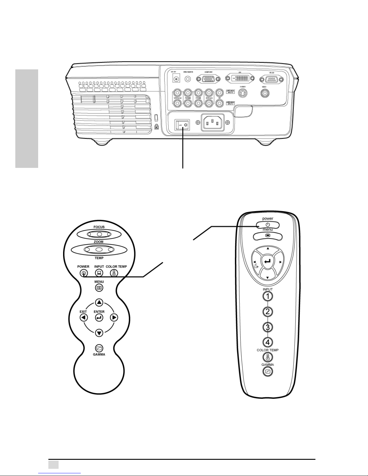
Follow these instructions to turn on projector.
1. Press the power switch on the rear panel to supply power to the projector.
2. Press the Power button on the control panel or remote control.
The fan starts running and the projector warms up. After the projector warms
up, (approximately 30 sec.) the image appears on the screen.
Press this switch to supply power to the projector.
Press the
power button.
Page 22

Chapter 2 – Connections
13
CONNECTIONS
Turning Off
Warning!
Follow these procedures exactly as written to avoid damage to the
lamp and projector.
1. Press the power button on the control panel or remote to open the
Power Down Menu. Select Yes and and press Enter. Alternately, you
can press the power button three times.
2. The lamp shuts off and the cooling fans continue to run for approximately two minutes to cool-down the lamp. During this cool-down
period, the control panel LEDs flash.
3. After the fans shut off and the control panel LEDs stop flashing, the
projector is in standby mode. The projector can be left in this state or
you can set the rear panel power switch to "o" to remove all power
from the projector.
This concludes this chapter. The next chapter describes operation of the projector.
Page 23
OPERATION
Chapter 3
Operation
The projector can be operated using the top control panel or the remote control. This
chapter describes using the control panel and the remote control.
Operating the Control Panel and Remote Control
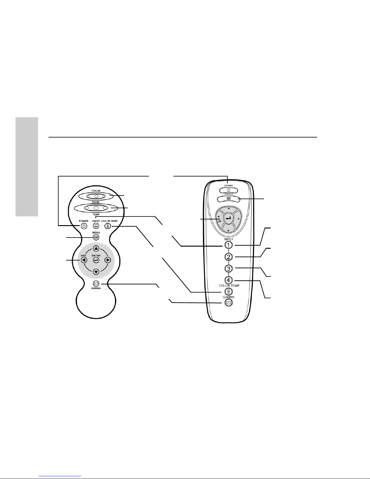
This section describes the functions available on the top control panel and the
remote control.
Zoom and Focus
The control panel has two dials to adjust the Zoom and Focus.
Zoom
Rotate the zoom dial to change the size of the image.
Focus
Rotate the focus dial to focus the image.
Power
Press the Power button to turn on the projector or to put the projector into standby
mode.
Zoom
Focus
Menu
Menu
Input 1
Input 2
Input 3
Input 4
OSD
Exit
Power
Color Temperature
OSD
Exit
(Computer/DVI)
(Component 1)
(Component 2)
Input
(S/Composite-Video)
Gamma correction
Page 24
Chapter 3 – Operation
15
OPERATION
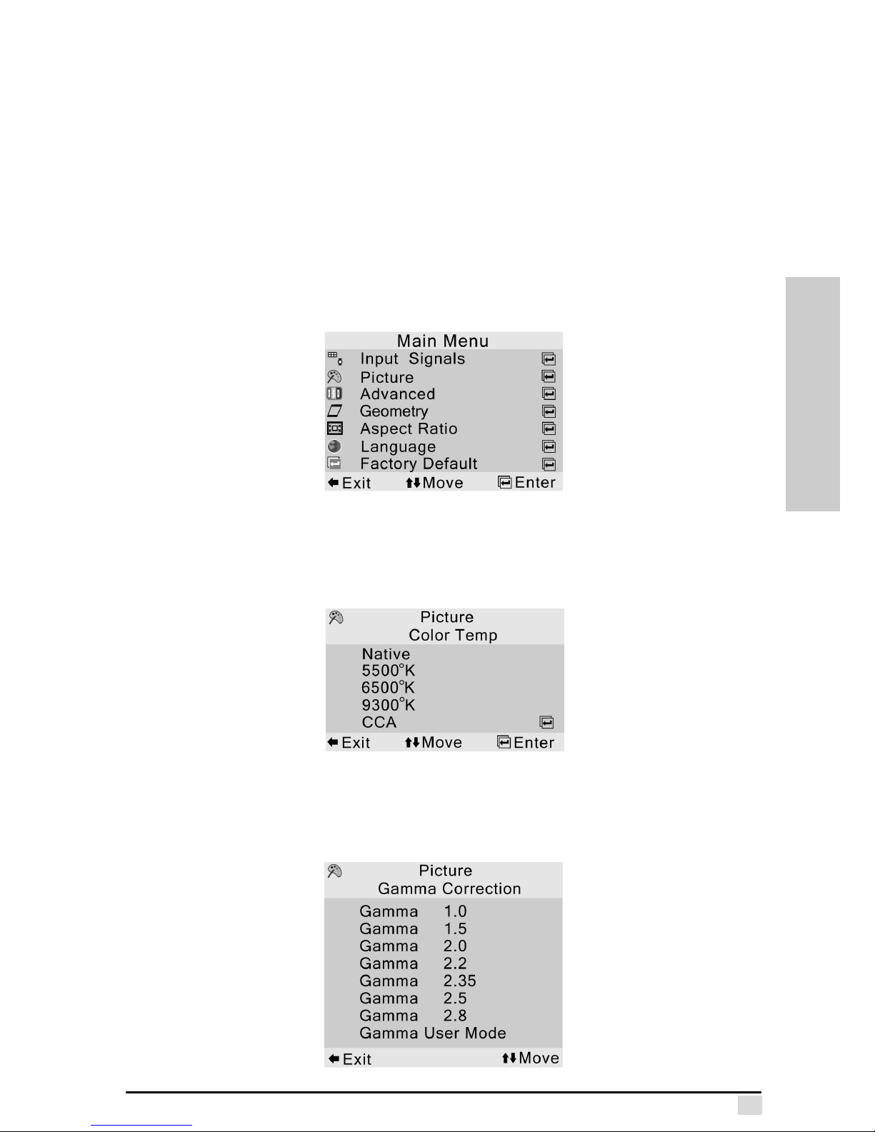
Input
Press the input button on the control panel to switch between the inputs. On the
remote control, press the number corresponding to the source mode you want:
– Input 1 – computer or DVI Mode
– Input 2 & 3 – component video 1&2
– Input 4 – S-Video/Composite Video
A screen at the bottom of the image shows which mode is currently selected. See
“Input Signals” on page 19 for more information.
Menu
Press this button to open the OSD menus. Refer to Chapter 4 for a full description of
the OSD menu functions.
Color Temperature
Press this button to set the color temperature of the image. See “Color Temp” on
page 20 for more information.
Gamma
Press the Gamma button on the remote control to adjust the gamma correction. See
“Gamma Correction” on page 21 for more information.
Page 25
Chapter 3 – Operation
16
OPERATION
Navigation Buttons
Press the up and down arrow buttons to scroll vertically through the menus. Press
the Enter button to open submenus and enter. Use the Exit button to go to the pre-
vious menu.
The Remote Control
The remote control provides a convenient way to control the projector.
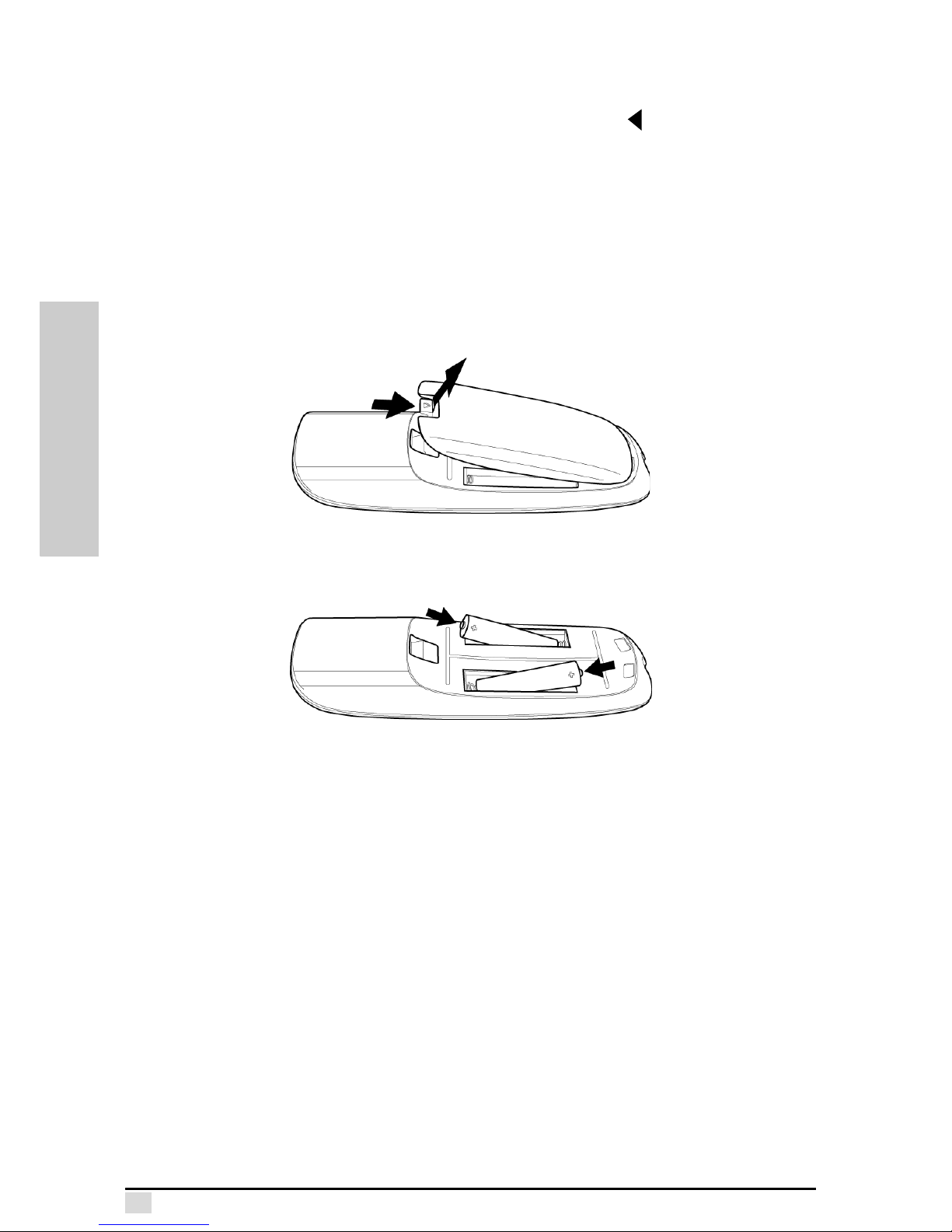
Installing Remote Control Batteries
Refer to the following illustrations and instructions on installing the remote control
batteries.
1. Press the battery cover latch and pull the battery cover open.
2. Insert two AAA batteries into the battery compartment, observing the polarity
marks in the battery compartment casing.
Using as a Wired Remote Control
To save battery power and use the remote control when line-of-sight access to the
remote control sensors is inconvenient, connect the included remote control cable
between the remote control and the projector using the Wire Remote jack on the rear
panel. Refer to “Wired Remote Control” on page 11.
Page 26
Chapter 3 – Operation
17
OPERATION
Setting Up the Projector
Follow these tips when setting up the projector.
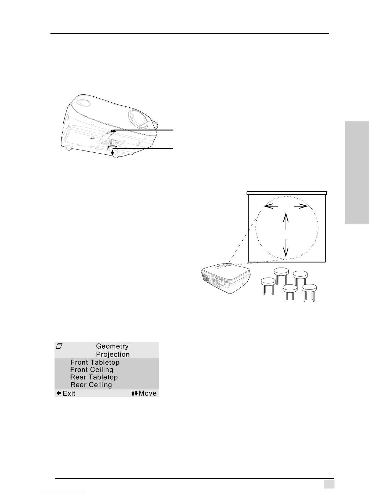
Adjustment Peg
Use the adjustment peg on the base of the projector to adjust the height of the projected image.
Keystone Correction
Choose the keystone function in the
Geometry submenu to adjust the image
shape when the projector is at an angle
to the screen.
Adjusting the Projection Distance
Position the projector perpendicular to
the screen with all feet flat to achieve
optimal image quality.
Move the projector forward if the edges
of the image are distorted. Ensure that
the distance from the projector to the
screen is between 0.9 to 10.6 meters.
Geometry Projection
Ensure that you have selected the best
mode for your environment.
This concludes this chapter. The next chapter covers the On-Screen Display (OSD)
menus.
Adjustment
peg
Adjustment peg
release
1. Push and hold the adjustment
peg release.
2. Raise the front of the projector.
3. Let go of the peg release to
secure the adjustment peg.
4. Turn the adjustment peg foot
pad to fine tune the height.
• Slide Shot (Left and Right)
• Provides ±40° horizontal and
±14° vertical keystone correction.
±14°
±40°
• Front Desktop: projecting forward from a
desktop or table.
• Front Ceiling: projecting forward from a
ceiling mount. Inverts the image vertically.
• Rear Tabletop: projecting from a table
onto a rear projection screen. Inverts the
image Horizontally.
• Rear Ceiling: projecting from a ceiling
mount onto a rear projection screen.
Inverts the image horizontally and vertically.
Page 27
OSD MENUS
Chapter 4
OSD Menus
About the OSD Menus
You can configure the Premiere 50HD DLP Projector by using the On Screen Display (OSD) Menus. The OSD menus enable you to set advanced features of the projector, including setting the input signal type, brightness, contrast, sharpness, color
tint, and display language, among other things.
To access the OSD Menus, press the OSD Menu button on your remote control unit
or the control panel. You can navigate through the OSD Menus by using the Up,
Down, Right and Left buttons. Currently selected items are highlighted in yellow.
There is an OSD Background menu that enables you to change the OSD Menu color
scheme.
Configuration settings are saved automatically when selected on the screen.
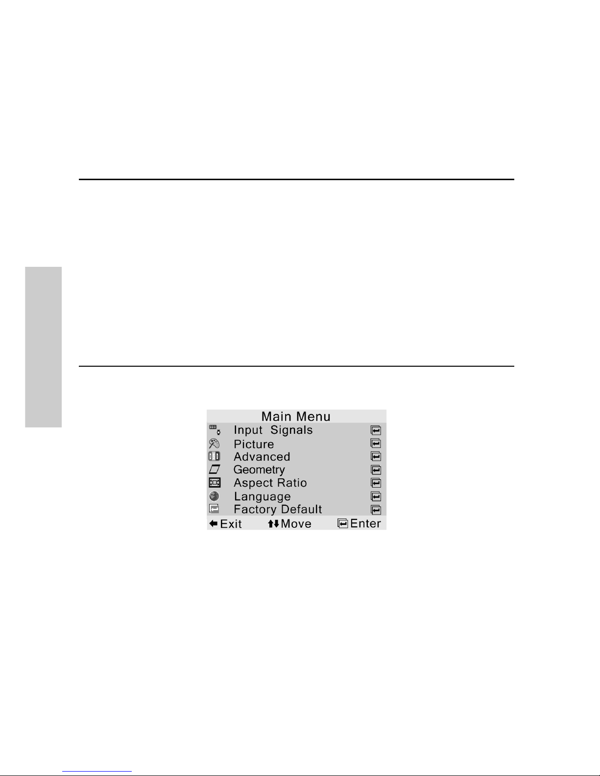
Main Menu
The Main Menu allows you to access the various submenus as shown below.
The following sections cover each submenu in the Main Menu:
Input Signals
‡ page 19
Picture
‡ page 19
Advanced
‡ page 22
Geometry
‡ page 26
Aspect Ratio
‡ page 27
Language
‡ page 28
Factory Default
‡ page 28
Page 28
Chapter 4 – OSD Menus
19
OSD MENUS
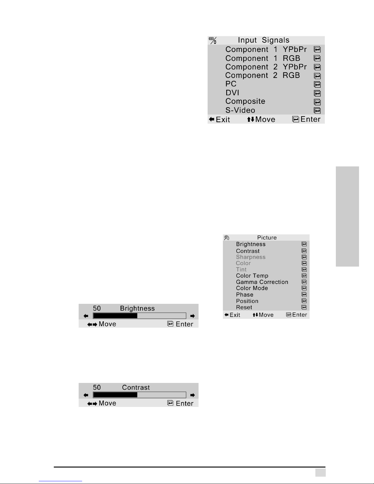
Input Signals
The Input Signals menu lets you specify
the signal type for the input into your projector. The following input signal types are
available.
Component 1&2 YPbPr
Select a YPbPr, SDTV, or HDTV component input source.
Component 1&2 RGB
Select an RGB, RGBH+V, or RGBHV
input source.
PC
Use this option to select the computer input.
DVI
Use this option to select the DVI input.
Composite
Use this option to select the Composite Video input source.
S-Video
Use this option to select the S-Video input.
Picture (Video Only)
The Picture menu lets you adjust the following
options for your image.
Brightness
Use this option to adjust the overall brightness
of your image. Use this control in conjunction
with contrast to fine-tune the display. The scale
is from 0 to 100. The default setting is 50.
Contrast
Use this option to adjust the contrast of your image. Use this control in conjunction
with brightness to fine-tune the display. The scale is from 0 to 100. The default setting is 50.
Sharpness
Use this option to adjust the clarity and focus of the image. This item is available for
both video and graphic sources. The scale is from 0 to 11. The default setting is 9.
Page 29
Chapter 4 – OSD Menus
20
OSD MENUS
Color
Use this option to adjust the color saturation of the image. This item is only available
for video sources. The scale is from 0 to 100. The default setting is 50.
Tint
Use this option to adjust the tint of your image. Press to make the image more
green. Press to make the image more purple. This item is only available for video
sources. The scale is from 0 to 100. The default setting is 50.
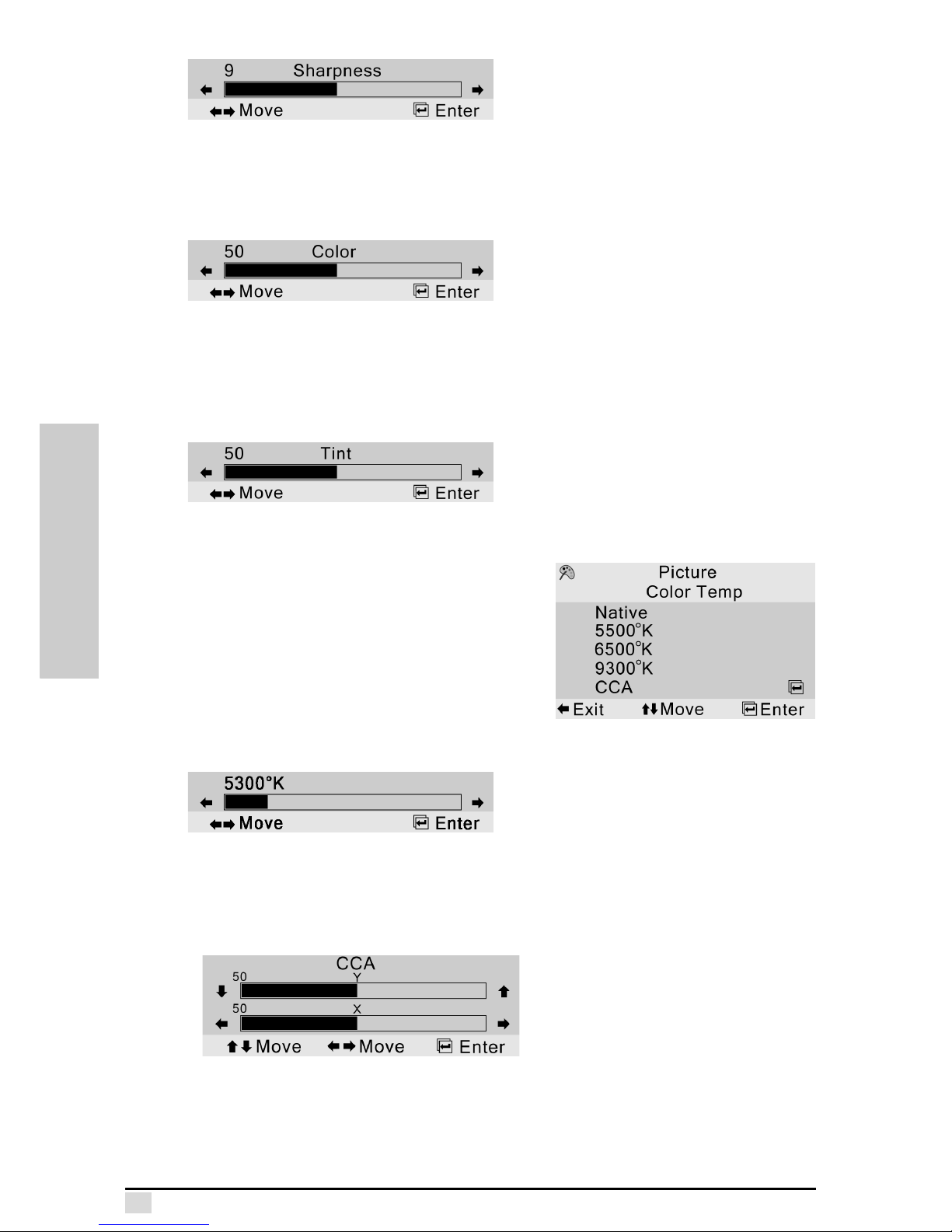
Color Temp
Use this option to adjust the Color Temperature
of your image.
Higher color temperatures make the image look
cool with a bluish hue. Lower color temperatures make the image look warmer with a reddish hue. The native color temperature usually
falls between 7200-8800
o
K.
Select User Mode and press Enter to adjust the
color temperature manually. The default setting is Native.
Press and to raise and lower the color temperature in steps of 100 degrees.
The minimum value is 4000 degrees; the maximum value is 14000 degrees.
Select CCA and press Enter to adjust the X,Y Color temperature.
Page 30
Chapter 4 – OSD Menus
21
OSD MENUS
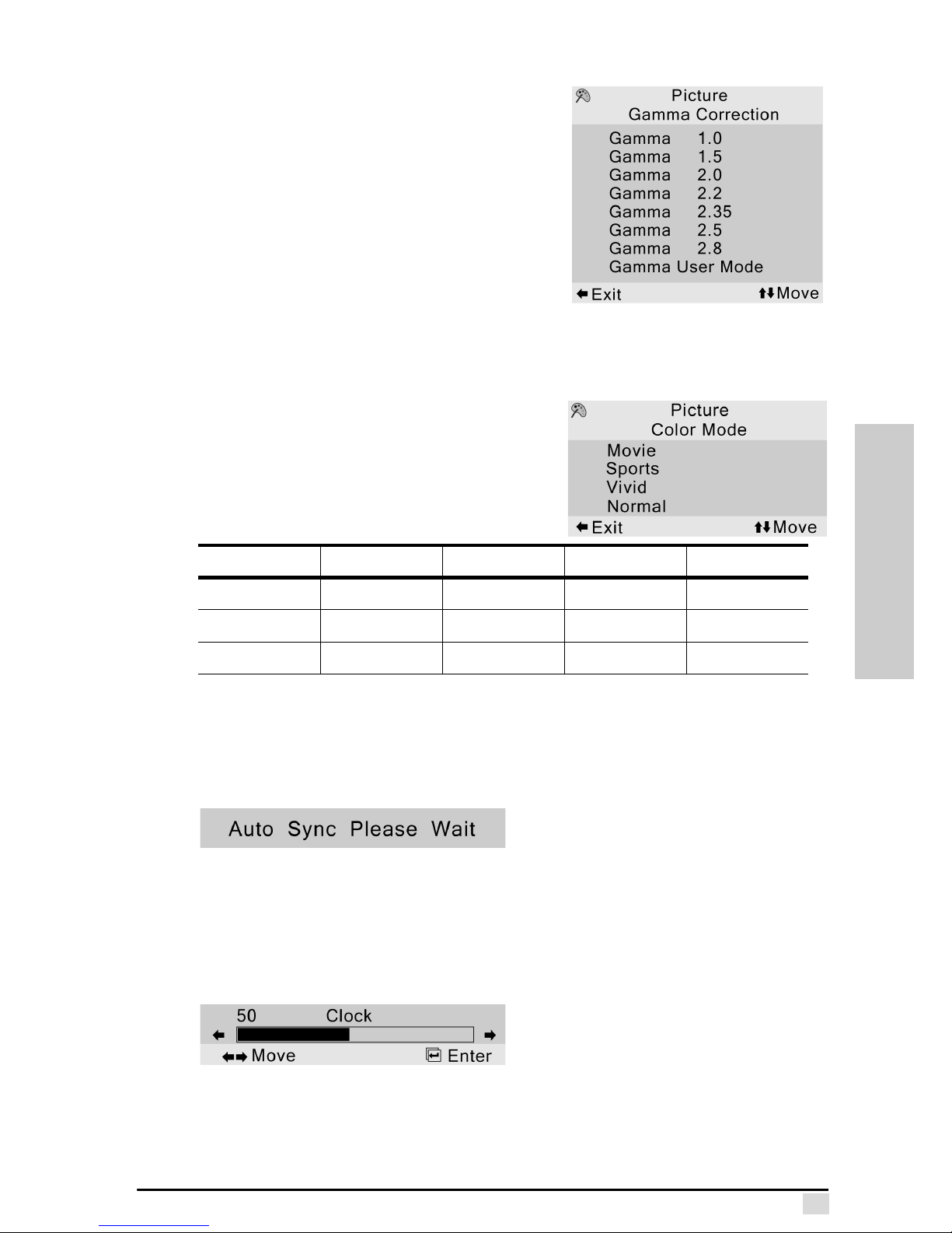
Gamma Correction
Use this option to adjust the Gamma Correction
of your image. Default setting is gamma 2.2.
Gamma curves for all input sources can be set
using gamma user mode. Users can use the
Gamma Manager utility to adjust or create
gamma curves as desired. The Gamma Manager can be found on the bundled CD installation kit or downloaded from our Web site. Refer
to Appendix C for more information on installing
and using the utility.
Gamma correction provides one linear gamma
and six non-linear gamma corrections — 1.0, 1.5, 2.0, 2.2, 2.35, 2.5, 2.8 — default
setting is Gamma 2.2.
Color Mode
Use this option to adjust the Color Mode of your
image. Four different modes are available with
preset values for brightness, contrast, sharpness, color, and tint for video input signals.
The table below shows the presets for the different settings.
Auto Tune (Computer Source Signal only)
Auto tune automatically adjusts the clock, phase, and position settings to match the
PC input. Select Auto Tune and press Enter. The following message is displayed on
the screen while the projector adjusts the settings:
Wait for the message to disappear before continuing.
Clock (Computer Source Signal only)
Clock enables you to adjust the display pixel number to help stabilize the display.
Use this function in conjunction with phase to adjust the display quality. Scale is from
0 to 100. The default setting is 50.
MOVIE SPORTS VIVID NORMAL
Brightness 42 55 35 50
Contrast 58 60 65 50
Sharpness 8 9 11 7
Page 31
Chapter 4 – OSD Menus
22
OSD MENUS
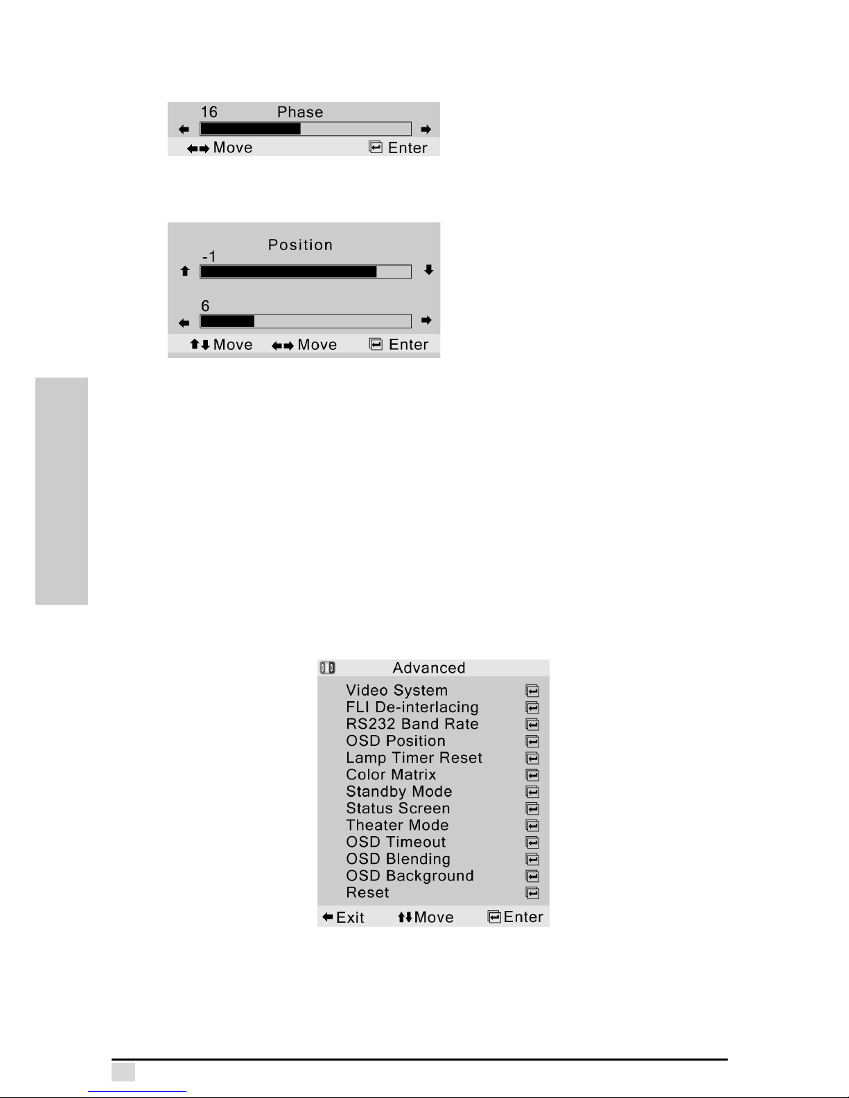
Phase
Phase lets you adjust the focus and clarity of the display. Scale is from 0 to 31.
Position
Position enables you to center the display vertically and horizontally.
Press to move the display upward. Press to move the display downward. Press
to move the display to the left. Press to move the display to the right.
Reset
Select Reset and press Enter to reset the picture settings to the factory defaults.
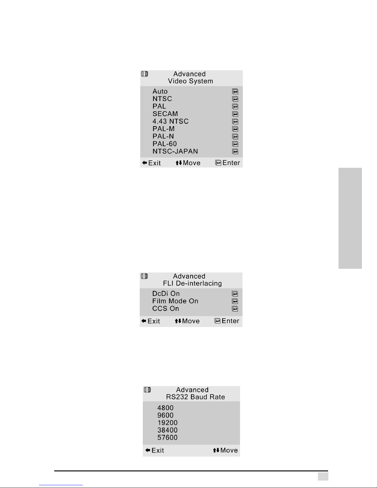
Advanced
The Advanced menu lets you configure the OSD position, reset the lamp timer, set
the standby mode, view a status screen, and set other options.
Page 32
Chapter 4 – OSD Menus
23
OSD MENUS
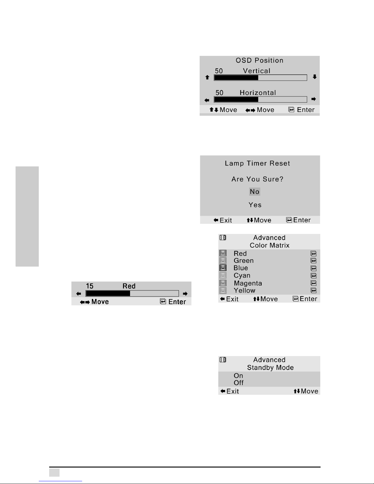
Video System
This option allows you to manually select the video standard for the composite and
S-Video inputs.
FLI De-interlacing
This option allows you to control how the projector processes video signals.
Setting DcDi to on helps to smooth the edges of objects in progressive scan and
interlaced images.
Setting Film Mode to on optimizes how 3:2 and 2:2 pull down conversions are performed.
Setting CCS to on helps prevent the cross color contamination that can be found in
some composite and S-Video inputs. By default, all of these settings are on.
RS232 Baud Rate
This option allows you to change the RS232 Baud Rate for serial communciations.
Refer to Appendix E for more information.
Page 33
Chapter 4 – OSD Menus
24
OSD MENUS
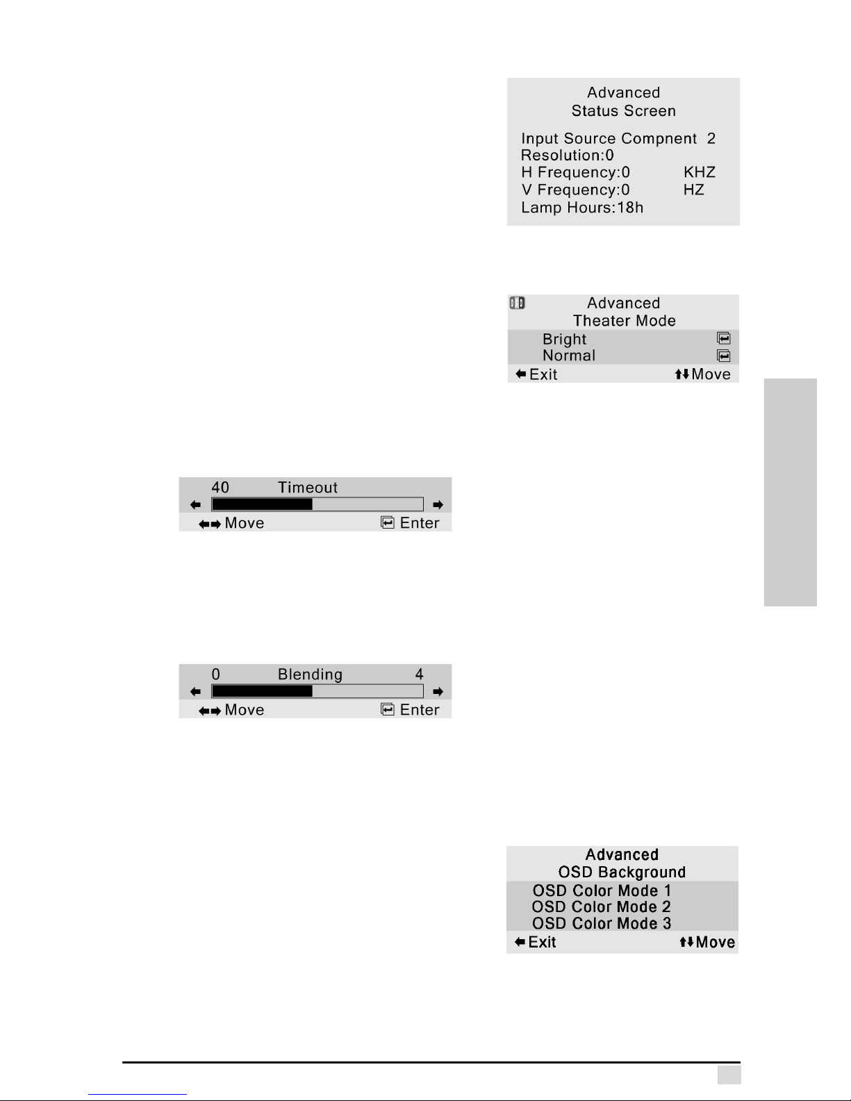
OSD Position
Enables you to set the position of the
OSD menu.
Press to move the OSD display
upward. Press to move the display
downward. Press to move the display
to the left. Press to move the display to
the right. The OSD vertical and horizontal
position can be set from 1 to 100 in 5
increment steps.
Lamp Timer Reset
Lamp Timer Reset is used to reset the
lamp counter.
You should reset the counter after you
install a new lamp. The cumulative lamp
usage time is shown in the Status Screen.
Color Matrix
Color Matrix is used to adjust the primary (Red,
Green, and Blue) and secondary (Cyan,
Magenta, and Yellow) color saturation. The
default setting is 30. Select a color and press
Enter to view the settings bar:
Press to decrease the color saturation. Press to increase the saturation.
Standby Mode
Standby Mode enables you to set the system to
power off automatically if no input is detected.
The following options are available:
• On: the system goes into standby mode
if it does not detect any input signal for 10
minutes, after which a countdown begins. After five minutes the system shuts
down.
• Off: standby mode function is disabled.
Page 34
Chapter 4 – OSD Menus
25
OSD MENUS
Status Screen
The status screen displays current system configuration parameters.
Theater Mode
Theater Mode is used to change the brightness
of light in white portions of the image.
When Bright mode is selected, the white light is
increased 20% more than in normal mode. PC
signal and DVI signal = Bright Mode. Video signal = Normal Mode
OSD Timeout
Timeout is used to set how long the OSD will stay open if no buttons are pressed.
Range is from 5 to 100 seconds. The default value is 40 seconds.
OSD Blending
Blending is used to set the transparency of the OSD menu, enabling you to see the
image behind the menu (from 0 to 40 in steps of one). The default setting is 0.
OSD Background
This item enables you to select the OSD color scheme.
OSD Color Mode 1 Background is Green
OSD Color Mode 2 Background is Magenta
OSD Color Mode 3 Background is Black
Reset
Select this option to set all items in the Advanced submenu to their factory default
values.
Page 35
Chapter 4 – OSD Menus
26
OSD MENUS
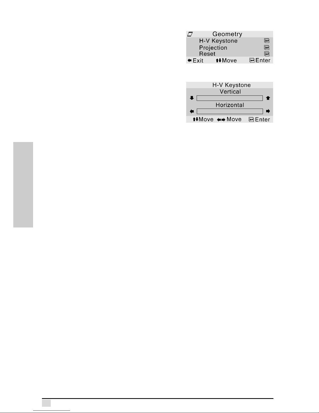
Geometry
The Geometry menu lets you configure the horizontal and vertical keystone and projection
placement settings.
H-V Keystone
This option enables you to set the horizontal
and vertical keystone values.
The vertical and horizontal options are as follows:
• Vertical: -7 ~ 7 (±14°)
• Horizontal: -20 ~ 20 (±40°)
Page 36
Chapter 4 – OSD Menus
27
OSD MENUS
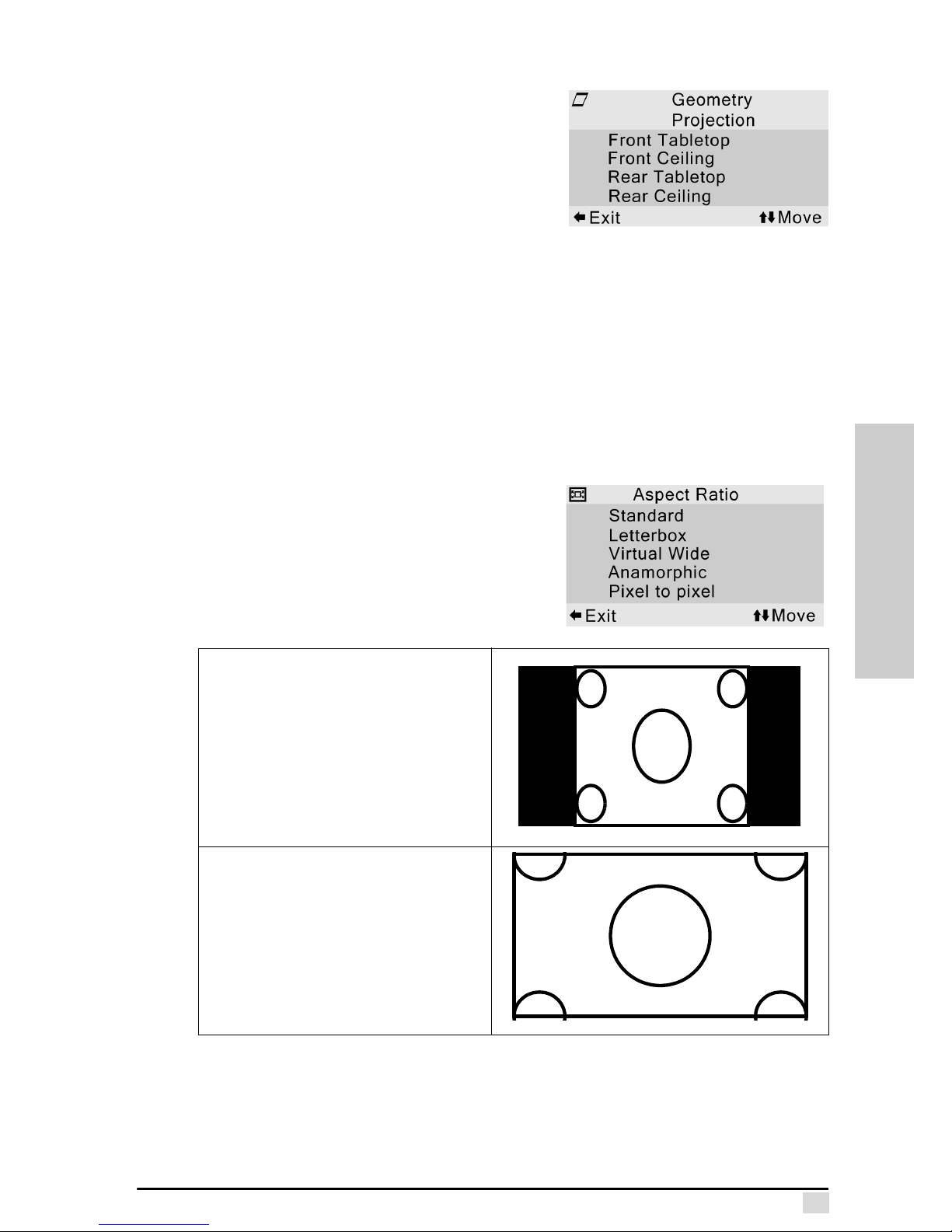
Projection
Enables you to configure the projector for
reversed image setup and ceiling mounting.
The following options are available:
• Front Tabletop: normal image, used for
forward facing projection.
• Front Ceiling: Image inverted vertically.
Used for forward-facing, ceiling-mounted
projection.
• Rear Tabletop: Image reversed horizontally. This is used for rear projection.
• Rear Ceiling: Image inverted vertically and reversed horizontally. This is used
for rear ceiling-mount projection or rear-projection using a mirror.
The default setting is Front Tabletop
Reset
Select this option to set all items in the Geometry submenu to their factory default
values.
Aspect Ratio
The Aspect menu enables you control how the
projector resizes the input image.
The following options are available:
Standard
• Resolution 960 x 720
• 4:3 input scaled to fit display
height
• Width scaled to maintain 4:3
aspect ratio
• Black bars on left and right (taking
up 25% of the whole display)
Letterbox
• Resolution 1280 x 720
• 4:3 input scaled to fit display width
• Height scaled to maintain 4:3
aspect ratio: 1280 x 960
• 25% of the entire image on the top
and bottom is cropped
Page 37
Chapter 4 – OSD Menus
28
OSD MENUS
Language
This menu sets the OSD display language.
The following languages are available:
• English
•Spanish
•German
•French
• Italian
Factory Default
This item sets all menu and submenu items to their factory defaults.
This concludes this chapter.
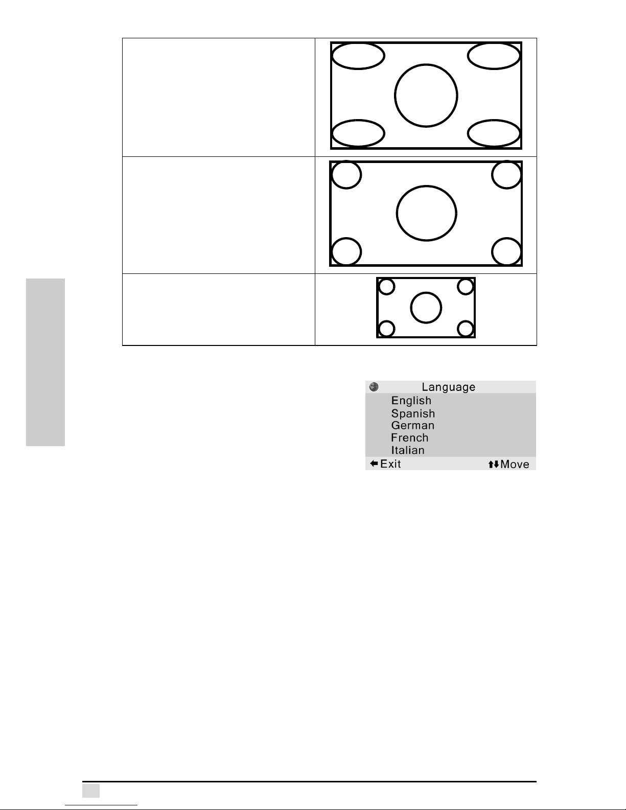
Virtual Wide
• Resolution 1280 x 720
• Correct geometry in middle
(stretches edges of image)
Anamorphic
• Resolution 1280 x720
• 4:3 input is stretched to fit 16:9
display
• Stretches entire image.
Pixel to Pixel
Maintains input signal resolution. May
have black borders around image.
Page 38
SPECIFICATIONS
Appendix A
Specifications
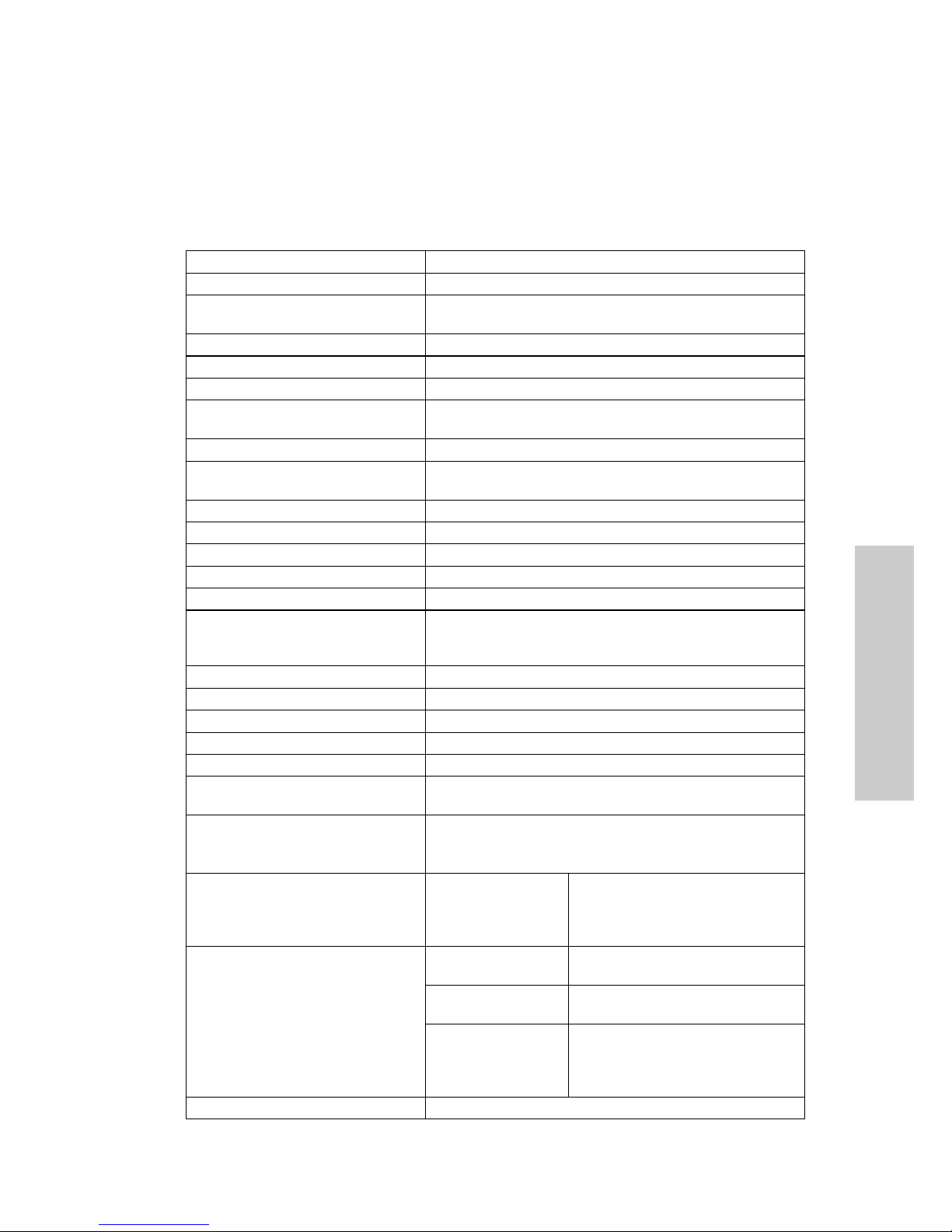
Product Specifications
Item Description
Model No. Premiere 50HD DLP Projector
Display Single DMD Panel with five-speed six-segment color
wheel
Panel Size 0.8-inch
Display Type Single Panel HD2 DMD Chip by Texas Instruments
Resolution 1280 x 720 dots
Lens Manual Zoom & Focus,
Zoom ratio: 1:1.2, F/2.4. f=24-28.8 mm
Lamp 200 W VIP, life = 2,000 hours
Brightness 1000 ANSI Lumen – Bright Mode
800 ANSI Lumen – Normal Mode
Contrast Ratio 1700:1 or Above
Uniformity 90%
Horizontal Scan Line 720 lines for DTV & 480 lines for NTSC
Screen Size 30 ~ 300 inches
Throw Ratio (16:9) 1.34:1 ~ 1.608:1
Aspect Ratio 16:9 Native, and 4:3
Supports Letterbox, Standard, Virtual Wide,
Anamorphic, Pixel to Pixel
Power Requirement AC 100V ~ AC 240V, 50/60Hz
Power Consumption 300W max., 6.0W standby
Operation Temperature 5°C ~ 35°C
Storage Temperature -20°C ~ 60°C
Acoustic Whisper quiet ≤ 31 dBA
Video System Digital TV(480p/576p/720p/1080i),
NTSC-M,N,60,4.43,Japan/PAL-M,N,60/SECAM
Computer Format
SXGA/XGA/SVGA/VGA/MAC640*480@67
MAC832*624@75/MAC1024*768@75
High Clarity image compression
I/O Connectors Component Video
(5RCA*2)
•Y,Pb,Pr
•Y,Cb,Cr
• R, G, B, H, V
• R, G, B(Sync on Green)
Graphic • DVI-D
• PC (VGA 15 pin D-Sub)
Standard Video • S-Video
• Composite Video
Others • RS-232 9 pin D-Sub
• Mini Jack for Wire Control
• DC12V Output for Motorized
Screen Control
IR Receiver Front & Rear
Page 39
MAINTENANCE
Appendix B
Maintenance
Maintenance
The Premiere 50HD DLP Projector has been constructed to provide years of operation. Refer to the following sections to maintain and troubleshoot your projector.
Lamp Maintenance
The projector lamp has an average life of 2,000 hours. Maintain proper ventilation
and keep the air filter clean to keep the lamp operating throughout its lifetime. Do not
subject the projector to unnecessary vibration to excessive vibration or shock may
rupture the lamp.
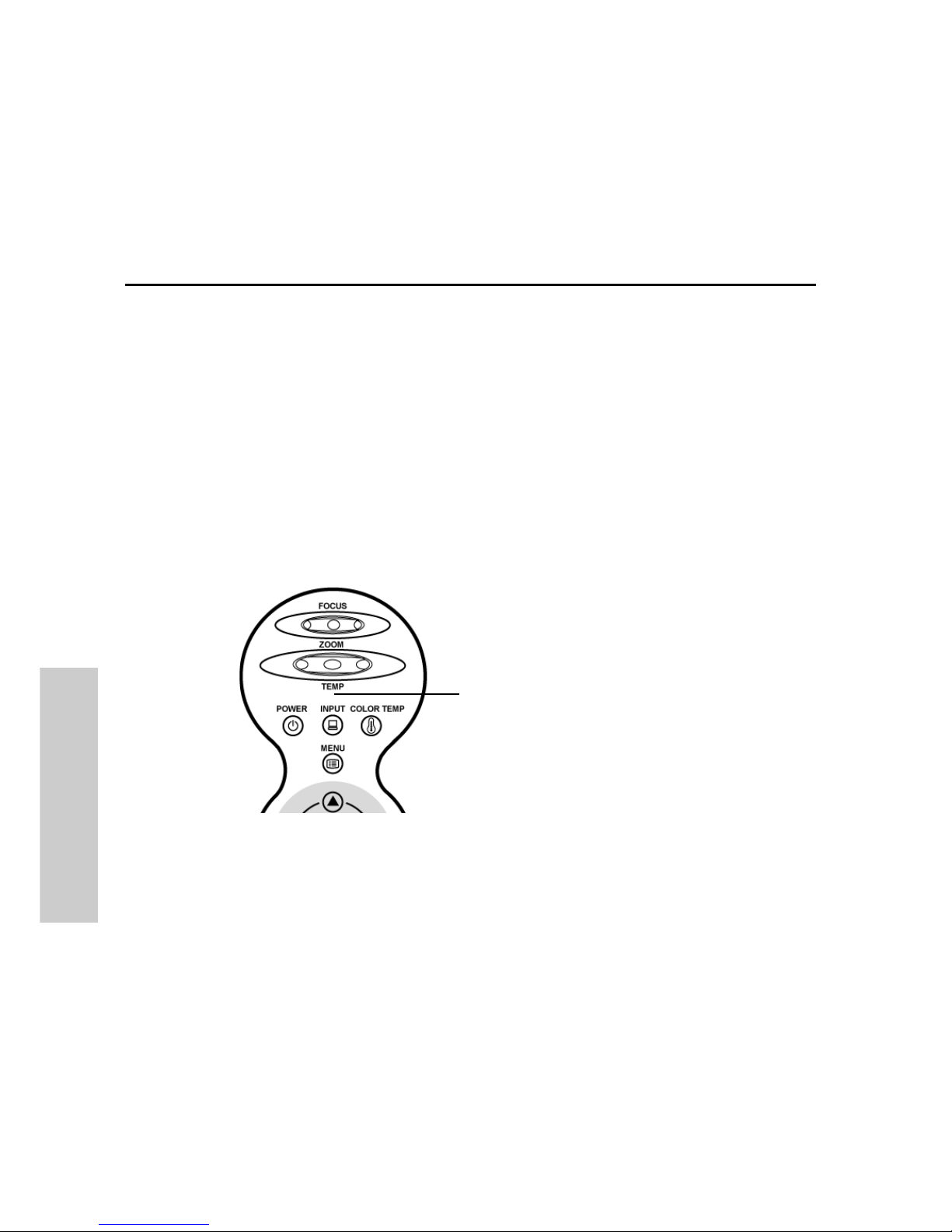
Temperature LED
The over temperature alarm LED on the control panel alerts you when the projector
lamp becomes too hot.
If the LED illuminates during operation, the lamp will shut off and the cooling fans will
continue to run for approximatedly two minutes. You should ensure that the airflow
around the projector is sufficient, and that the air filters are not clogged to ensure that
the projector has proper ventilation.
Over temperature alarm LED
Page 40
Appendix B – Maintenance
31
MAINTENANCE
Checking the Lamp Usage Time
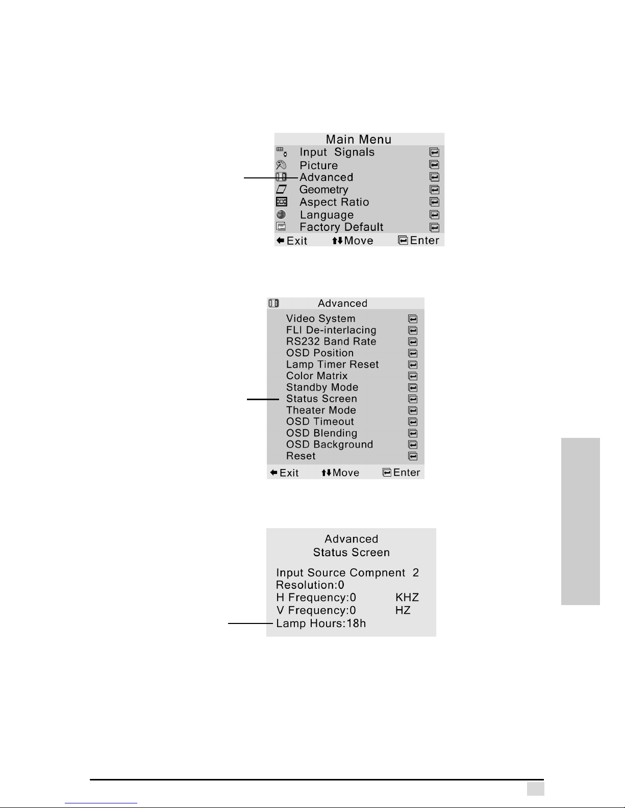
The projector lamp has the average life of 2,000 hours. The OSD menus provide you
with a utility to monitor the lamp usage time.
1. Press Menu on the control panel or remote control.
2. Select Advanced.
3. In the Advanced submenu, select Status Screen.
4. The Status Screen displays the number of hours the lamp has been lit.
When the lamp usage time reaches 2,000 hours, it is time to replace the lamp.
Select
Advanced
Select
Status
Screen
Lamp
Usage
Time
Page 41
Appendix B – Maintenance
32
MAINTENANCE
Replacing the Lamp
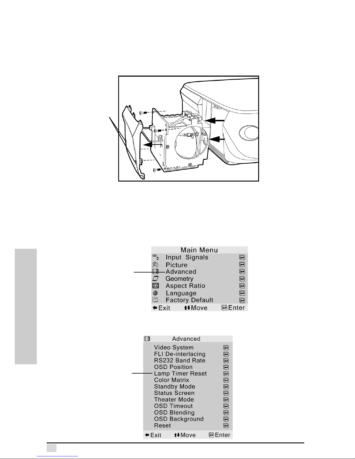
Turn off the projector and remove the power cord prior to replacing the lamp. Allow
the lamp to cool for at least 15 minutes prior to opening the lamp door. (Please see
"Turn Off" on page 13)
Follow these instructions to replace the lamp.
1. Loosen the two screws on the lamp door (A).
2. Remove the three screws securing the lamp to the chassis (B).
3. Pull the lamp handle (C) to remove the lamp module (D).
4. Reverse the steps above to install the new lamp module.
After you have installed the lamp, reset the lamp usage time in the OSD menus.
1. Press Menu on the control panel or remote control.
2. Select Advanced.
3. In the Advanced submenu, select Lamp Timer Reset.
B
D
B
B
A
C
Select
Advanced
Select
Lamp
Timer
Reset
Page 42
Appendix B – Maintenance
33
MAINTENANCE
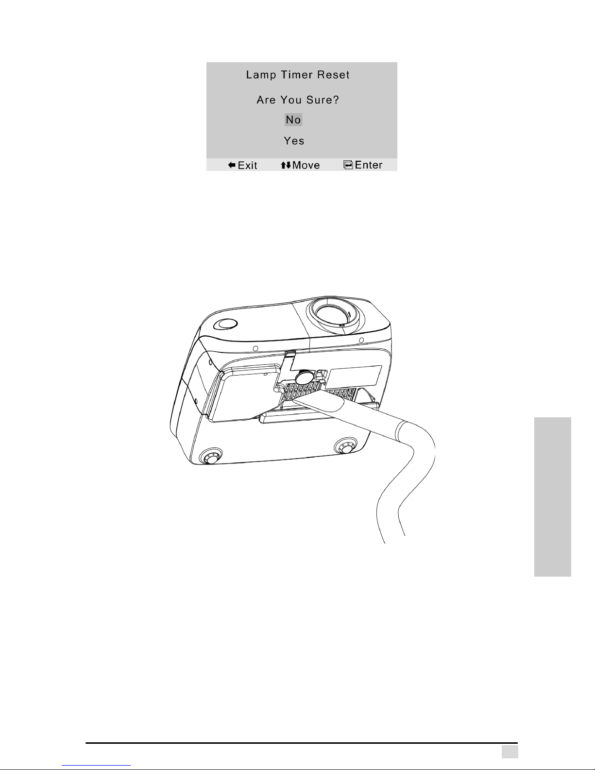
4. In the Lamp Timer Reset submenu, select Yes to reset the timer.
Cleaning the Air Filters
This projector is equipped with air filters to ensure the optimal operating condition of
the projector. Periodically clean the air filters by vacuuming them off with a vacuum
cleaner. The air filter should be cleaned every 100 hours of use. Clean the filters
more often when the projector is used in a dirty or smoky location.
Page 43
Appendix B – Maintenance
34
MAINTENANCE
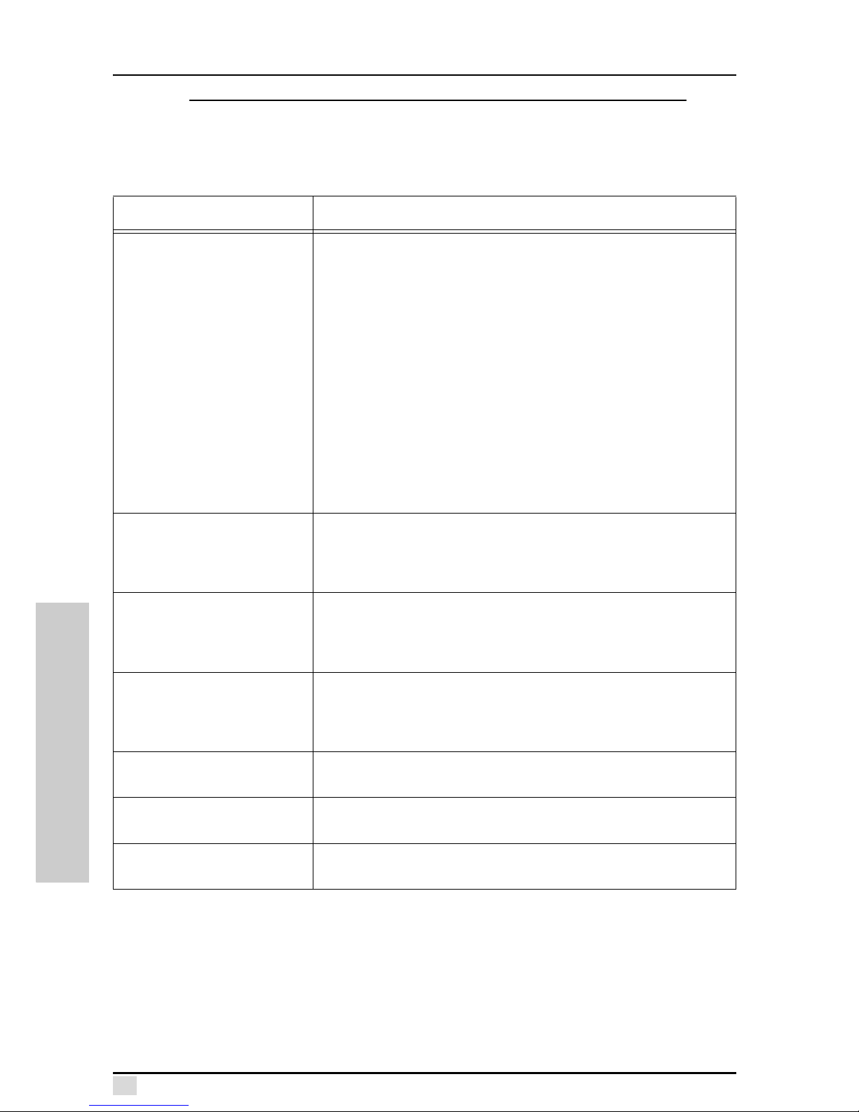
Troub le sh oo ti ng
Note: If you are having trouble with the display, use the auto sync feature
first PC input only (page 21), and reset to the default factory settings
(page 28). If the problem persists, adjust the OSD menu for better image
quality (Chapter 4).
Problem Check
No picture appears. • Ensure that the projector is plugged into the wall outlet. Check to
see if the wall outlet is connected to a wall switch and that the
wall switch is on.
• Ensure the power switch is turned on.
(See “Turning On/Off” on page 12)
• Ensure that the source setting is correct.
(See “Input Signals” on page 19)
• Ensure that the source device cables are correctly connected.
(See “Connections” on page 7)
• If you are using the remote control, ensure that the batteries are
good. If necessary, replace the batteries.
(See “Installing Remote Control Batteries” on page 16)
• Ensure that the contrast and brightness settings are not set to
the minimum position.
(See “Brightness” and “Contrast” on page 19)
• Ensure the lamp is installed.
Color is faded or poor • Ensure that the color and tint settings are correct.
(See “Color” and “Tint” on page 20)
• Ensure that the video system settings are correct.
(See “Video System” on page 23)
Picture is blurred • Adjust the zoom and focus. (See “Zoom and Focus” on page 14)
• Ensure that the projection distance is not too long or too short to
allow for proper focus. (See “Adjusting the Projection Distance ”
on page 17)
No OSD appears • Ensure that the projector is plugged in.
• If you are using the remote control, ensure that the batteries are
good. If necessary, replace the batteries.
(See “Installing Remote Control Batteries” on page 16)
Over temperature alarm LED
lights up
The projector is overheating. See “Temperature LED” on page 30.
Picture noise appears • Adjust the phase. (See “Phase” on page 22)
• Check the input cables.
Image is green on
INPUT 2&3 COMPONENT
Change the component input signal type. (See “Input Signals” on
page 19) Ensure the component cables are connected correctly.
Page 44

GAMMA MANAGER
Appendix C
The Gamma Manager Utility
About the Gamma Manager Utility
Gamma Manager may be an optional item for your projector, please check with your
sales agent.
The Gamma Manager Utility enables you to send user-defined gamma correction
values to the projector from your PC. Gamma correction provides more precise control over the brightness, contrast, and color.
This software operates under the Microsoft Windows XP/Me/2000/98SE/98/NT operating systems. This manual references only these Microsoft Windows Operating
Systems. Refer to the Microsoft Windows operation manual for details.
Required Hardware and Software
Gamma Manager requires the following hardware and software for operation.
• PC running under Microsoft Windows XP/Me/2000/98SE/98/NT
• 233 MHz Pentium CPU or higher is recommended
• 800 x 600 display capable of displaying 65,536 colors or more
• At least 32 MB of memory
• At least 10 MB hard disk free space
• RS-232C serial port
• CD-ROM drive to install the software
Note: This software may not operate normally if the computer configuration and serial port settings are not set correctly or other serial devices
are connected to the computer.
Page 45
Appendix C – The Gamma Manager Utility
36
GAMMA MANAGER
Connecting the Projector to the PC
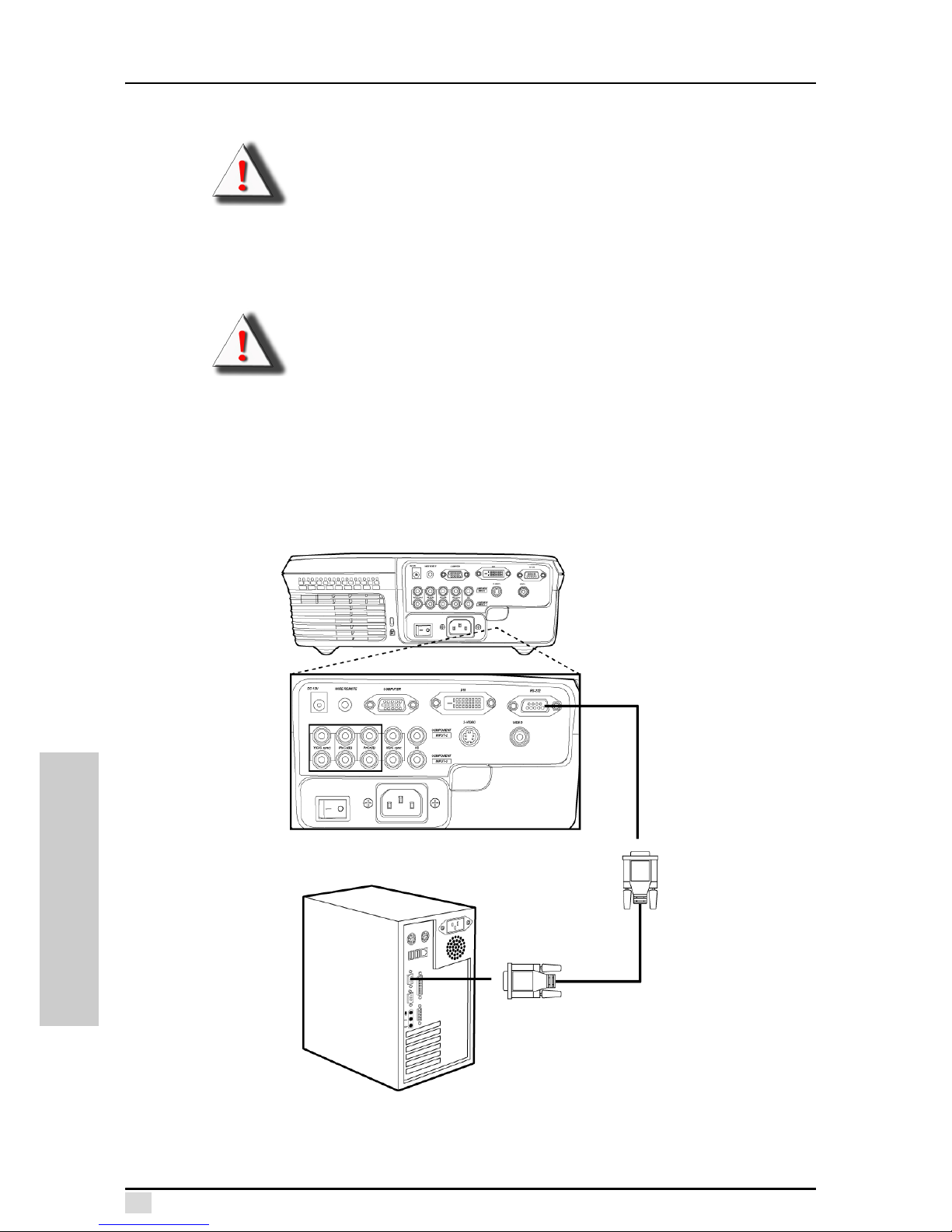
This software requires the use of an RS-232C serial cable.
CAUTION
Before connecting, be sure to turn both the projector and the computer off. After
making the connection, turn the projector on first. The computer should always be
turned on last.
CAUTION
The VGA cable pin NO.11 should be Digital Ground or NO Pin.(D-Sub 15 pin cable)
If there is any type of signal on pin 11, the user gamma and other fuctions will not
work properly.
Connecting the Projector to a PC
Refer to following illustration to connect the projector to a PC.
Connect the male end
of the RS-232 cable to
the female RS-232
port on the projector.
Connect the female end
of the RS-232 cable to an
RS-232 port on the PC.
Page 46
Appendix C – The Gamma Manager Utility
37
GAMMA MANAGER
Installing the Software
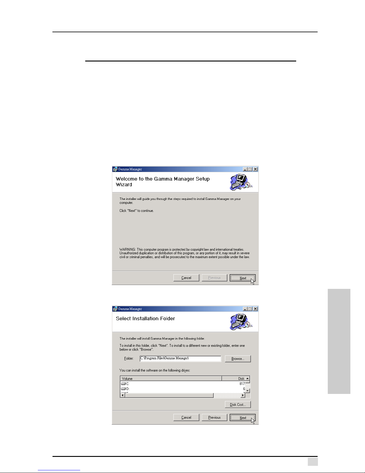
This software can be installed using the installation program on the CD installation kit
that came with the projector.
Notes:
• Ensure that your computer meets the required specifications (see “Required
Hardware and Software” on page 35).
• Quit all running applications before installing this software.
Follow these instructions:
1. Insert the installation kit CD in the CD-ROM drive.
2. Double-click the My Computer icon.
3. Double-click the CD-ROM drive icon.
4. Browse to the Gamma Manager folder.
5. Double-click Gamma Manager.msi. The Gamma Manager Setup Wizard
opens.
6. Click Next. You are prompted to select an installation folder.
7. Select the default location or browse to an alternate location.
8. Click Next. You are prompted to confirm the installation.
Page 47
Appendix C – The Gamma Manager Utility
38
GAMMA MANAGER
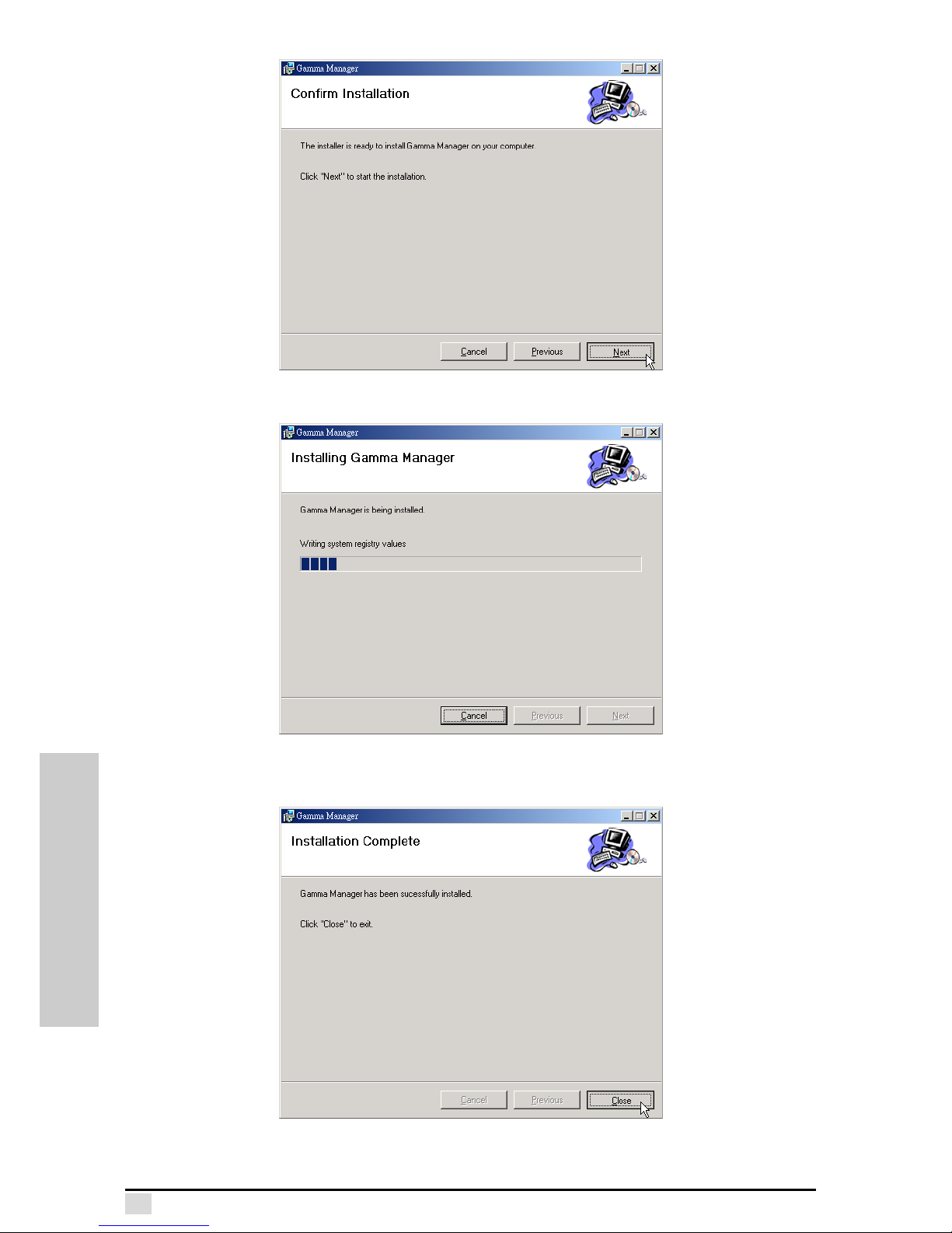
9. Click Next. The wizard installs the program.
After the Wizard installs the Gamma Manager, the following screen is displayed.
10.Click Close to finish the installation.
Page 48
Appendix C – The Gamma Manager Utility
39
GAMMA MANAGER
Uninstalling the Software
Always uninstall the software before installing an updated version. Ensure that the
software is closed before proceeding.
Follow these instructions to uninstall the software.
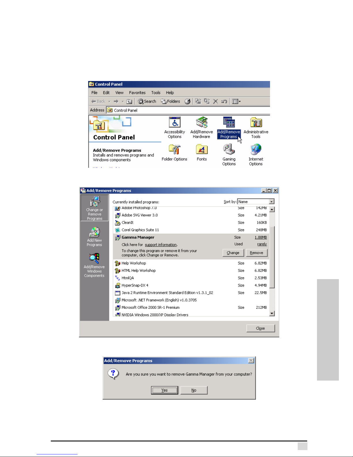
1. Click Start, Settings, then select Control Panel.
2. Double-click the Add/Remove Programs icon.
3. Select the NEXGEN Gamma Manager entry.
4. Click Remove. You are prompted to confirm uninstall.
5. Click Yes. The program is uninstalled.
Page 49
Appendix C – The Gamma Manager Utility
40
GAMMA MANAGER
Using the Gamma Manager Utility
This section covers basic Gamma Manager Utility operation. The Gamma Manager
enables you to adjust the light intensity of screen images by adjusting the display
screen brightness display. Gamma correction is also used to make the projector display match more closely the image from another monitor or other output device such
as a printer.
Note: Before starting the software, make sure that the projector and the
PC are correctly set up, and ensure that the PC and projector are connected. Refer to “Connecting the Projector to a PC” on page 36.
Starting the Gamma Manager Utility
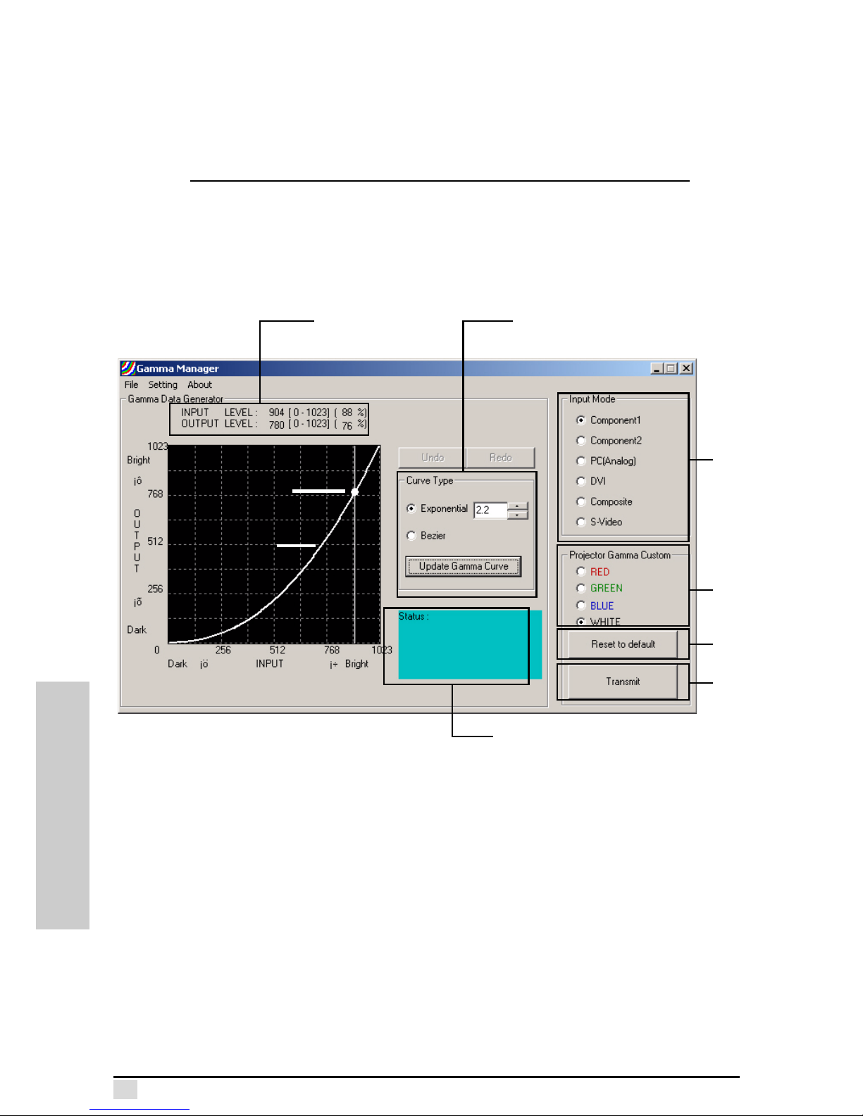
Click Start, Shortcut to Gamma.exe to open the Gamma Manager Utility.
1. Displays the gamma input/output levels.
2. Enables you to set the gamma curve type:
Exponential: sets the gamma curve based on the function OUTPUT=INPUT
n
where n is the number selected from the spin box. Use the up and down
arrows to increase or decrease n.
Bézier: sets the gamma curve based on a mathematical formula that assures
continuity with other Bézier curves.
3. Enables you to set the program input signal to that of the projector.
4. Enables you to adjust the red, green, and blue curves or white curves. When
white is selected, red, green, and blue are offset.
5. Press this button to reset all values to the factory default setting.
6. Press this button to transmit the adjusted gamma curve to the projector.
7. Displays program status.
1
2
3
4
5
6
7
Gamma Curve
control point
Gamma Curve
Page 50
Appendix C – The Gamma Manager Utility
41
GAMMA MANAGER
Using the Gamma Manager
Follow these instructions to get started using the Gamma Manager.
1. Connect the projector and PC using the RS-232 cable. See “Connecting the
Projector to a PC” on page 36.
2. Turn on the the projector.
3. Turn on the PC.
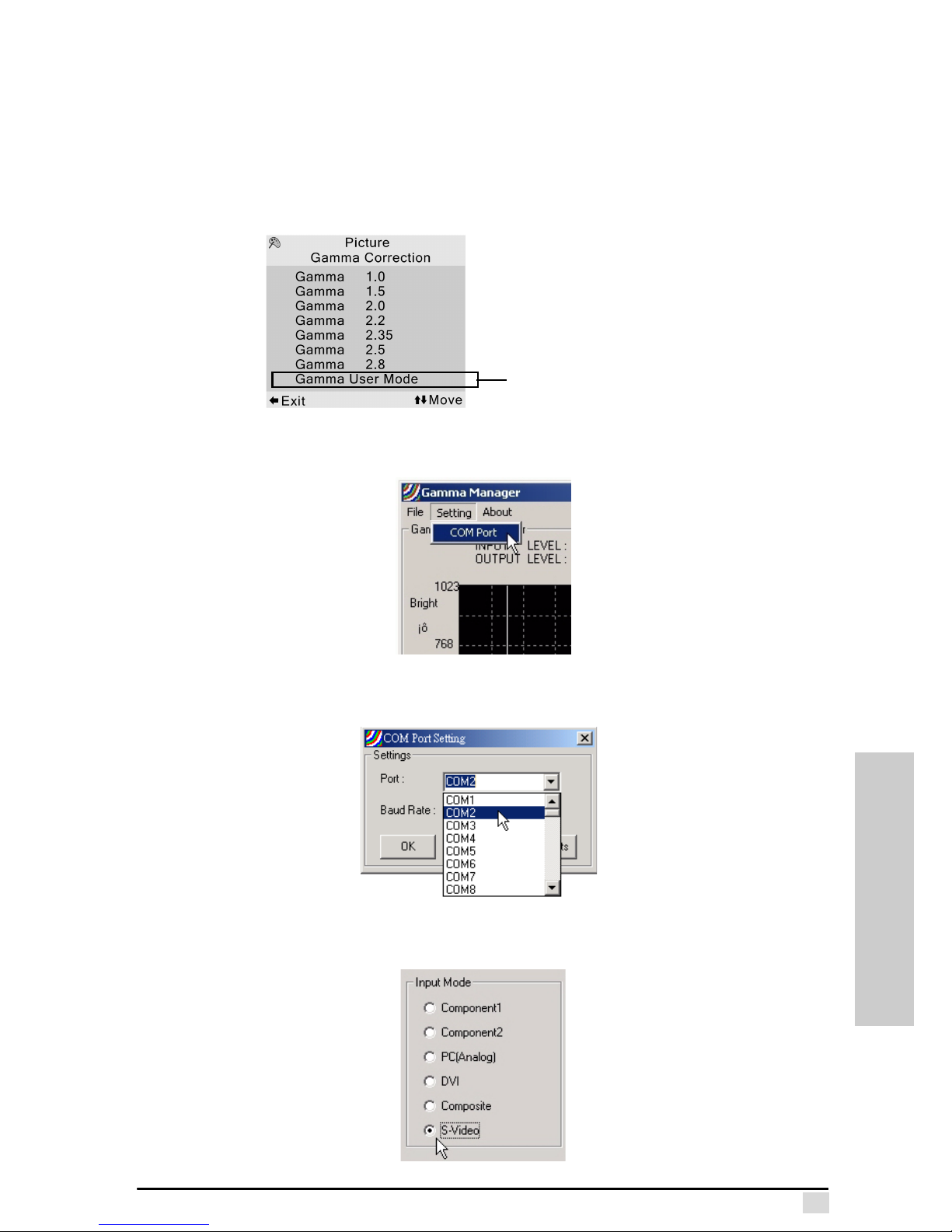
4. Set the projector Gamma Correction OSD menu to "Gamma User Mode".
5. Open the Gamma Manager.
6. Click Setting, COM Port.
7. In the COM Port Setting dialog, select the COM port from the drop-down list
that your projector is connected to.
8. Select the input mode
Gamma User Mode
Page 51
Appendix C – The Gamma Manager Utility
42
GAMMA MANAGER
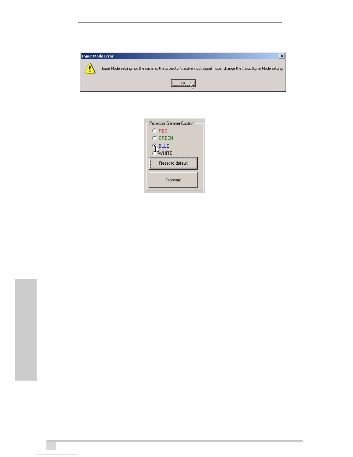
Note: You must select the same input mode that the projector is set at. If
you select a different input mode, you will receive the following warning
message.
9. Select Projector Gamma Custom to customize the gamma curve for a single
color.
10.Adjust the curve. You can adjust the curve in the Curve Type section, or you
can directly adjust it by using the mouse to drag the adjustment point.
Page 52
Appendix C – The Gamma Manager Utility
43
GAMMA MANAGER
Adjusting the Gamma Curve
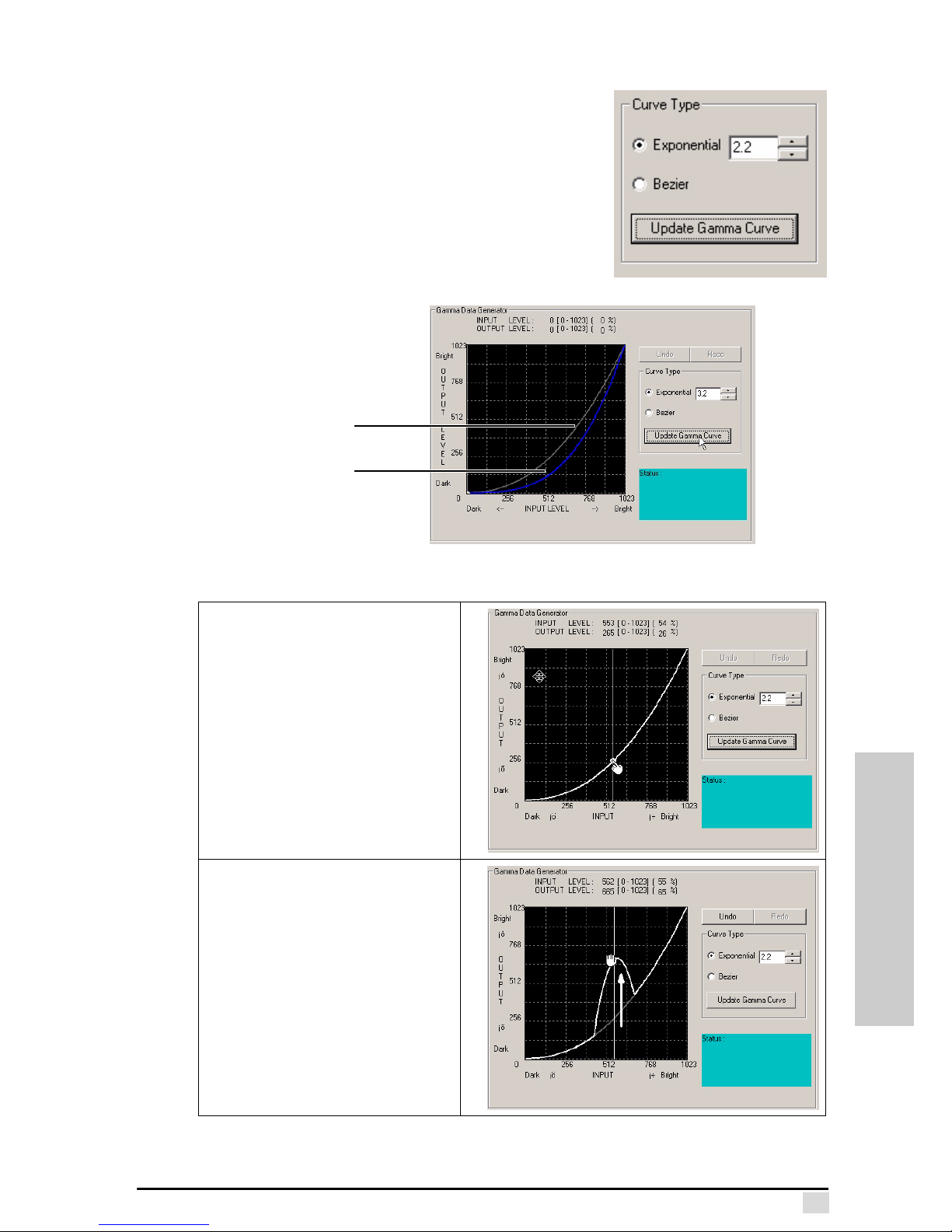
You can adjust the gamma curve using an exponential
or Bézier function.
Exponential
Exponential sets the gamma curve based on the func-
tion OUTPUT=INPUT
n
where n is the number
selected from the spin box. Use the up and down
arrows to increase or decrease n. The following illustration shows what happens when the exponential is
set at 3.2 and the color is blue
Click Update Gamma Curve to display the new curve. The previous curve is displayed in gray.
To directly adjust the curve, place
the cursor over the curve where
you want to adjust the gamma
value. The cursor turns into a
hand:
Click the line. The cursor
becomes a clenched hand. Drag
the line up or down to adjust the
curve and release.
Previous value
(grey)
New value
(blue)
Page 53
Appendix C – The Gamma Manager Utility
44
GAMMA MANAGER
Bézier
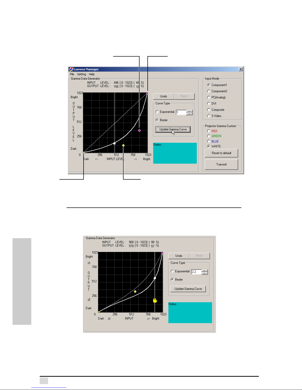
Bézier sets the gamma curve based on a mathematical formula that assures continuity with other Bézier curves. Click Bézier and then click Update Gamma Curve to
view the Bézier adjust screen.
Click and drag the control points to change the curve’s starting and ending points.
Note: When clicking the Bézier curve control points and end points, the
hand icon turns yellow.
Click the adjustment points and drag them to adjust the shape of the Bézier curve.
Yellow control point
Pink end pointPink control point
Yellow
end point
Page 54
Appendix C – The Gamma Manager Utility
45
GAMMA MANAGER
Setting a Gamma Curve Range
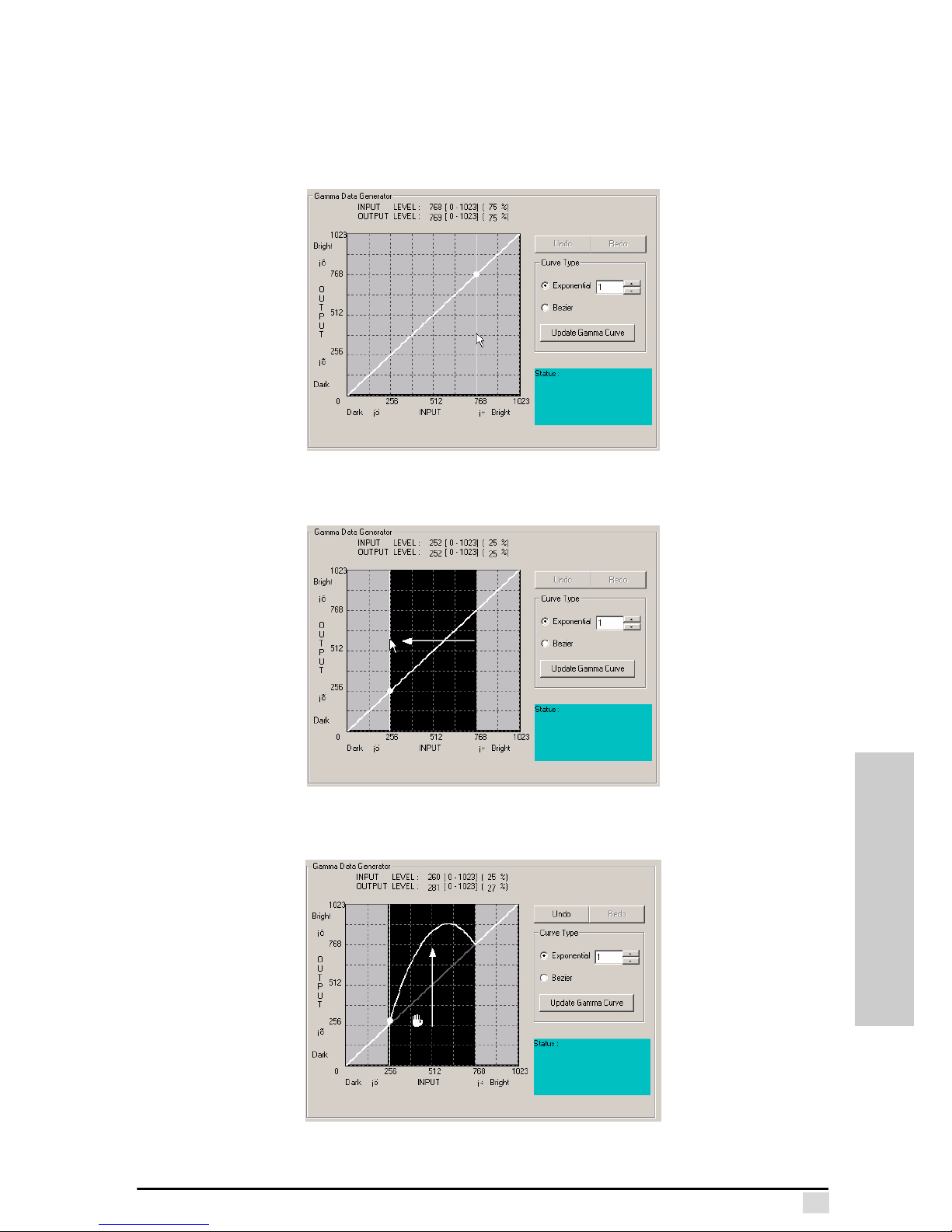
You can set a curve range for adjusting the gamma. When adjusting the gamma,
only the defined curve segment is changed.
1. Click the screen where you want to define a region boundary. Do NOT click on
the curve.
The output screen turns gray.
2. Drag the cursor to define the other boundary.
3. Adjust the curve by dragging the adjustment. The adjustment only affects the
line segment defined by the boundary.
Page 55
Appendix C – The Gamma Manager Utility
46
GAMMA MANAGER
Undoing a Setting
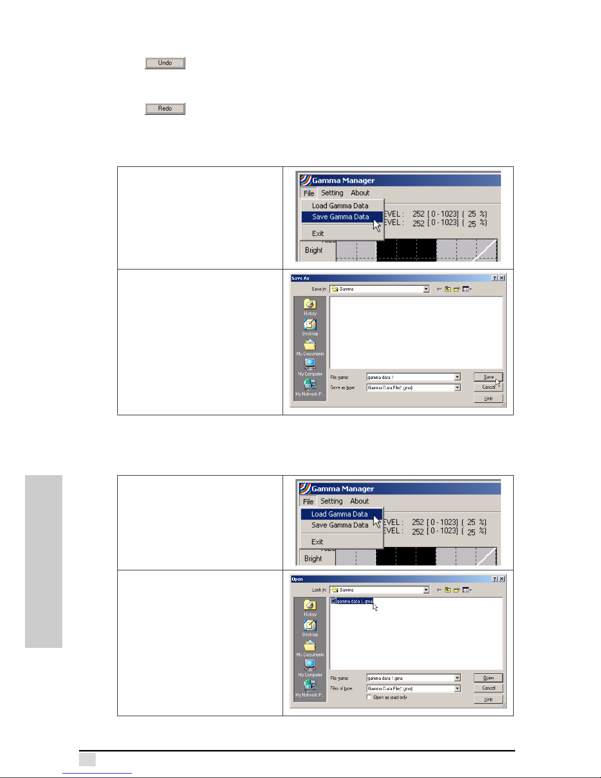
Click to revert the curve to its previous position.
Redoing a Setting
Click to revert the curve to its previous position.
Saving a Gamma Curve Configuration
After adjusting the curve to your satisfaction, you can save the configuration.
Loading a Gamma Curve Configuration
You can load saved gamma curve configurations for editing or sending to the projecor. Click File, Load Gamma Data:
Click File, Save Gamma Data.
Type a name for the gamma data
file. Files are stored in the
Gamma Manager subdirectory
with a GMA extension.
Click File, Load Gamma Data.
Click a configuration file and click
Open to load the configuration.
Page 56
THROW RATIO
Appendix D
Throw Ratio
About the Throw Ratio
Throw ratio refers to the ratio between the projector’s distance from the screen (or
throw distance) and the diagonal of the image projected on the screen. The following
pages provide throw ratio tables and graphics.
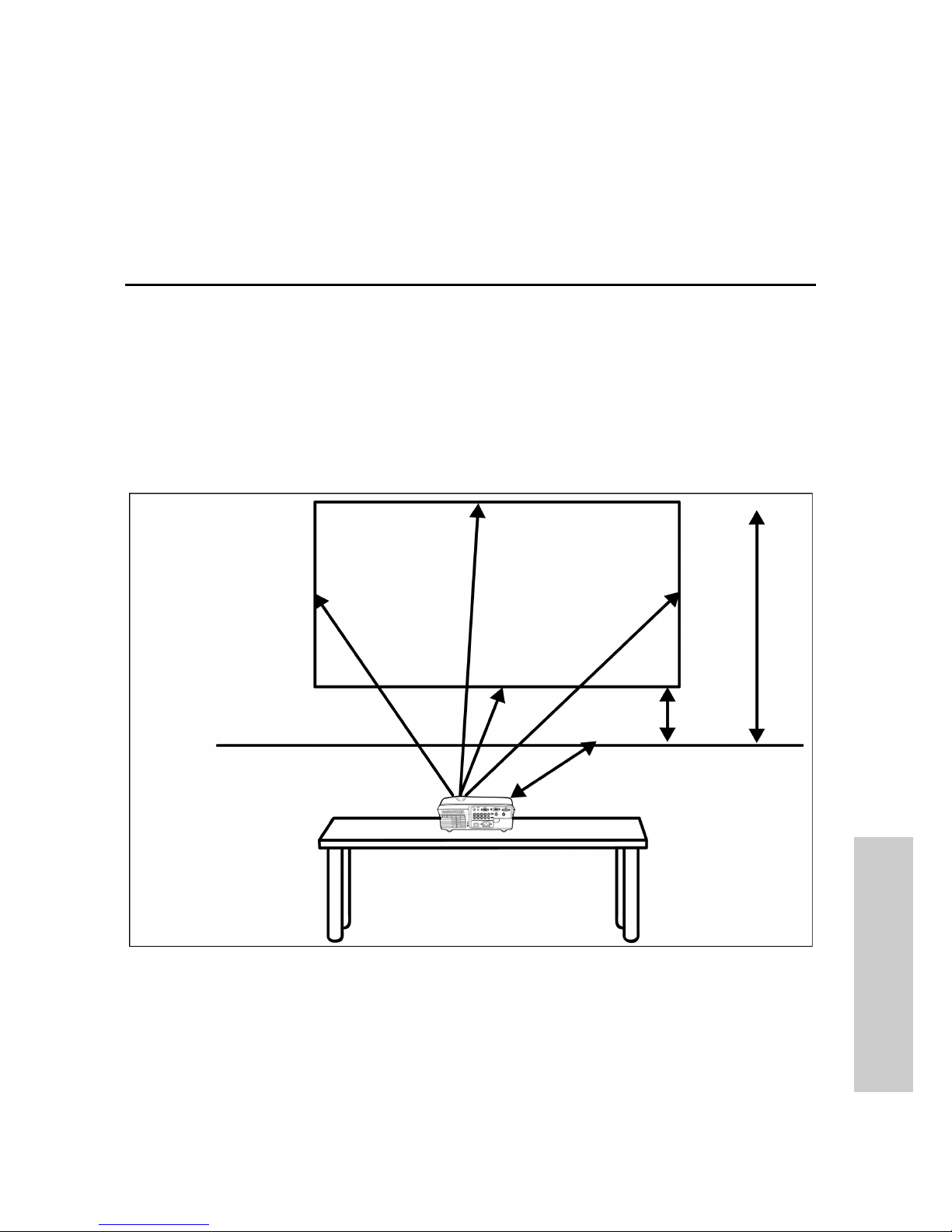
Desktop Installation
The following illustration and tables explain how to calculate the throw ratio for a
desktop configuration. The tables provide values for screen ratios of 16:9 and 4:3.
Desktop Installation
SCREEN
z1
z2
(Ground level)
y1, y2
Page 57
Appendix D – Throw Ratio
48
THROW RATIO
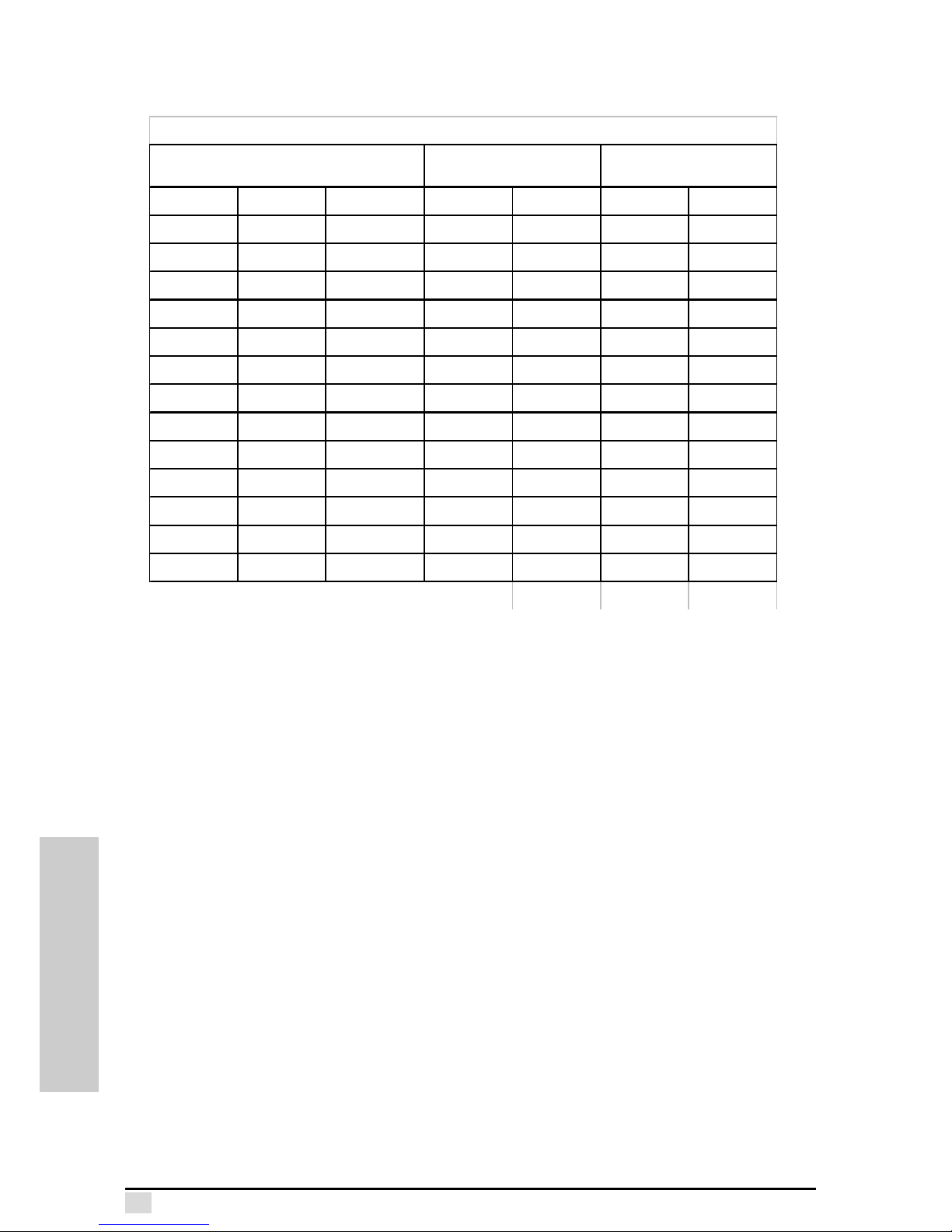
Desktop Installation — 16:9 Screen Size
Diag. Width Height Max Min Upper Lower
300” 261” 147” 10.68m 8.9m 4.59m 0.854m
250” 218” 123” 8.9m 7.416m 3.842m 0.729m
200” 174” 98” 7.12m 5.933m 3.095m 0.604m
150” 131” 74” 5.34m 4.45m 2.347m 0.48m
133” 116” 65” 4.735m 3.946m 2.093m 0.437m
106” 92” 52” 3.773m 3.145m 1.69m 0.37m
100” 87” 49” 3.56m 2.967m 1.6m 0.355m
92” 80” 45” 3.275m 2.729m 1.48m 0.335m
84” 73” 41” 2.99m 2.492m 1.361m 0.315m
72” 63” 35” 2.563m 2.136m 1.181m 0.285m
60” 52” 29” 2.136m 1.78m 1. 002m 0. 255m
40” 35” 20” 1.424m 1.187m 0.703m 0.205m
30” 26” 15” 1.068m 0.89m 0. 553m 0.18m
x Screen size
y1 Max projection Distance z1 Upper height from Desk
y2 Min projection Distance z2 Lower height from Desk
y1=x*0. 035599019 z1=x*0.014949939+0.105
z2=x*0.002496924+0.105y2=x*0. 029665849
Desk top installation
Scre en size (16:9)
Projection Distance
(m)
Height Above Desk
Page 58
Appendix D – Throw Ratio
49
THROW RATIO
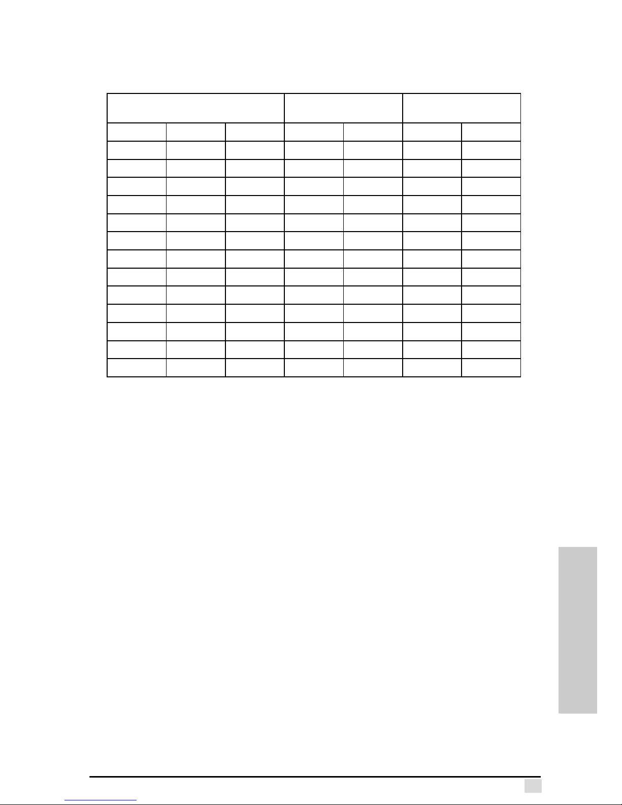
Desktop Installation — 4:3
Diag. Width Height Max Min Upper Lower
300” 240” 180” 13.07m 10.892m 5.594m 1.022m
250” 200” 150” 10.892m 9.076m 4.679m 0.869m
200” 160” 120” 8.713m 7.261m 3.764m 0.716m
150” 120” 90” 6.535m 5.446m 2.849m 0.563m
133” 106” 80” 5.794m 4.829m 2.538m 0.511m
106” 85” 64” 4.618m 3.848m 2.044m 0.429m
100” 80” 60” 4.357m 3.631m 1.935m 0.411m
92” 74” 55” 4.008m 3.34m 1.788m 0.386m
84” 67” 50” 3.66m 3.05m 1.642m 0.362m
72” 58” 43” 3.137m 2.614m 1.422m 0.325m
60” 48” 36” 2.614m 2.178m 1.203m 0.288m
40” 32” 24” 1.743m 1.452m 0.837m 0.227m
30” 24” 18” 1.307m 1.089m 0.654m 0.197m
x
Screen size
y1 z1
y2 z2
z1=x *0.030700699+0.105y1=x *0.04356608
y2=x *0.036305066 z2=x *0.003055736+0.105
Max projection Distance
Min projection Distance
Upper height from Desk
Lower height from Desk
Desk top installation
Scre e n size (4:3)
Projection Distance
(m)
Height Above Desk
Page 59
Appendix D – Throw Ratio
50
THROW RATIO
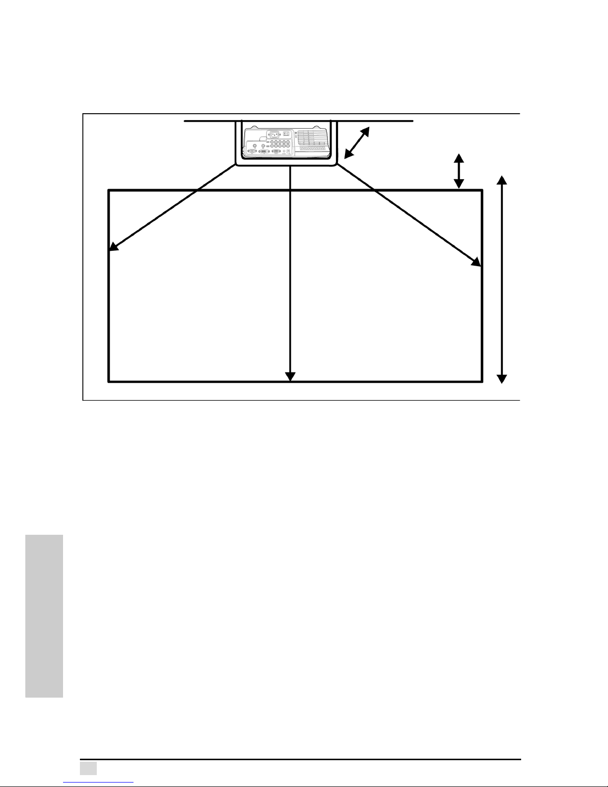
Ceiling Mount Installation
The following illustration and tables explain how to calculate the throw ratio for a ceiling mount configuration. The tables provide values for screen ratios of 16:9 and 4:3.
SCREEN
z1
z2
(Ceiling level)
y1, y2
Page 60
Appendix D – Throw Ratio
51
THROW RATIO
Ceiling Mount Installation — 16:9 Screen Size
Diag. Wi dth Height Max Min Uppe r Low e r
300” 261” 147” 10.68m 8.9m 0.854m 4.59m
250” 218” 123” 8.9m 7.416m 0.729m 3.842m
200” 174” 98” 7.12m 5. 933m 0.604m 3.095m
150” 131” 74” 5.34m 4.45m 0.48m 2.347m
133” 116” 65” 4.735m 3.946m 0.437m 2.093m
106” 92” 52” 3.773m 3.145m 0.37m 1.69m
100” 87” 49” 3.56m 2.967m 0.355m 1.6m
92” 80” 45” 3.275m 2.729m 0.335m 1.48m
84” 73” 41” 2.99m 2.492m 0.315m 1.361m
72” 63” 35” 2.563m 2.136m 0.285m 1.181m
60” 52” 29” 2.136m 1.78m 0.255m 1.002m
40” 35” 20” 1.424m 1.187m 0.205m 0.703m
30” 26” 15” 1.068m 0.89m 0.18m 0.553m
x Screen size z1 Long distance from ceiling mount
y1
y2 z2
z1=x*0.014949939+0.105y1=x*0.035599019
y2=x*0.029665849 z2=x *0.002496924+0.105
Max projection Distance
Min projection Distance
(bottom of the projector)
Shorter distance from ceiling mount
Ceiling mount installation
Scre en size (16:9) Proje ction Distance Distance from ceiling
Page 61
Appendix D – Throw Ratio
52
THROW RATIO
Ceiling Mount Installation — 4:3 Screen Size
Diag. Width Height Max Min Upper Lower
300” 240” 180” 13.07m 10.892m 1.022m 5.594m
250” 200” 150” 10.892m 9.076m 0.869m 4.679m
200” 160” 120” 8.713m 7.261m 0.716m 3.764m
150” 120” 90” 6.535m 5.446m 0.563m 2.849m
133” 106” 80” 5.794m 4.829m 0.511m 2.538m
106” 85” 64” 4. 618m 3.848m 0.429m 2.044m
100” 80” 60” 4. 357m 3.631m 0.411m 1.935m
92” 74” 55” 4. 008m 3.34m 0.386m 1.788m
84” 67” 50” 3.66m 3.05m 0.362m 1.642m
72” 58” 43” 3. 137m 2.614m 0.325m 1.422m
60” 48” 36” 2. 614m 2.178m 0.288m 1.203m
40” 32” 24” 1. 743m 1.452m 0.227m 0.837m
30” 24” 18” 1. 307m 1.089m 0.197m 0.654m
x
creen size z1
y1
y2 z2
z1=x*0.030700699+0.105
Long distance from ceiling mount
Shorter distance from ceiling mount
(bottom of the projector)
y1=x *0.04356608
y2=x *0.036305066 z2=x*0.003055736+0.105
Max projection Distance
Min projection Distance
Ceiling mount installation
Screen size (4:3) Projection Distance Distance from ceiling
Page 62
RS-232 COMMUNICATION
Appendix E
RS-232 communication
RS-232C communication
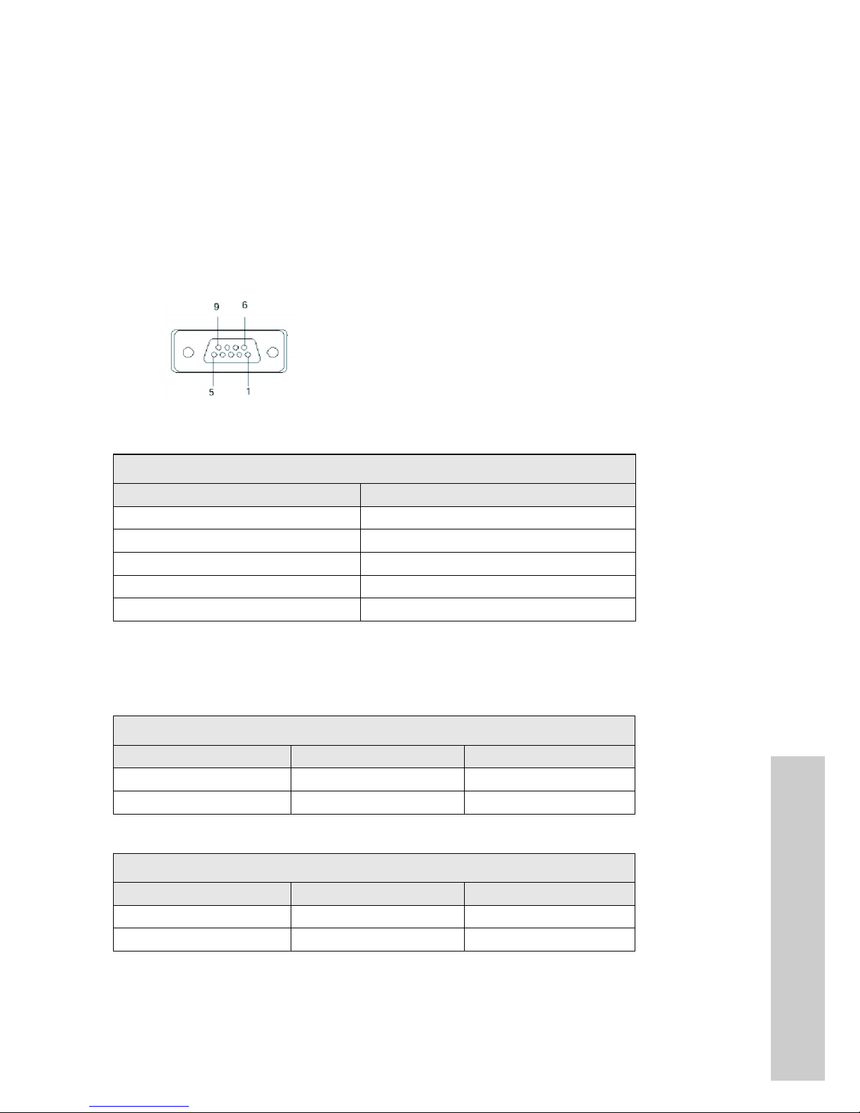
Connect the computer and projector while both are off and make sure the projector is
turned on first. The connector scheme (from left to right) is:
• top (pin 9,8,7,6): not used, not used, not used, not used
• bottom (pins 5,4,3,2,1) : ground, not used, receive data, send data, not used.
RS-232C jack D-sub 9-pin
Communications setting
1.Command data
Command data (3) + Setting value (2).
2.Requesting projector status (Read command)
3.Changing the projector settings (Write command)
Computer (Windows) - HyPer Terminal
Command Or Read command
In Hyper Terminal, Press Enter Key
(Ex.BRI 20 Sets the brightness to 20)
RS-232 Port Settings
Setting Value
bits per second 57600
Data bits 8
Parity None
Stop bits 1
Flow control None
RS-232 Port Settings
Function Command Response
Brightness (BRI ??) (0-99)
Contrast (CON ??) (0-99)
Write Command Examples
Function Command Response
Brightness (BRI 10) Brightness Write OK
Contrast (CON 10) Contrast Write OK
Page 63
Appendix E – RS-232 communication
54
RS-232 COMMUNICATION
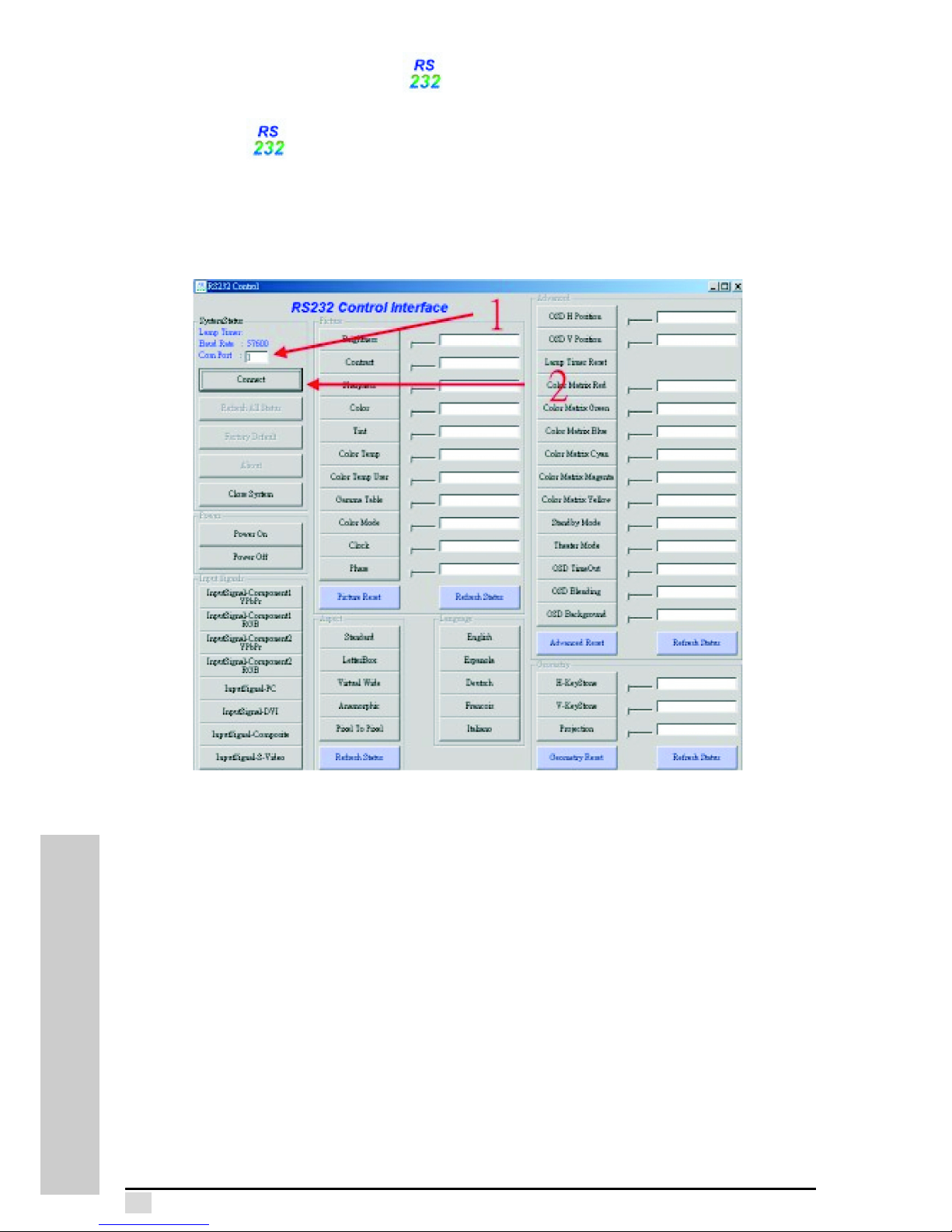
Computer (Windows) - RS232ControlAP.exe
Setup RS232ControlAP
1.Setting Com Port
2.Connect System
Page 64
Appendix E – RS-232 communication
55
RS-232 COMMU-
RS-232 COMMUNICATION
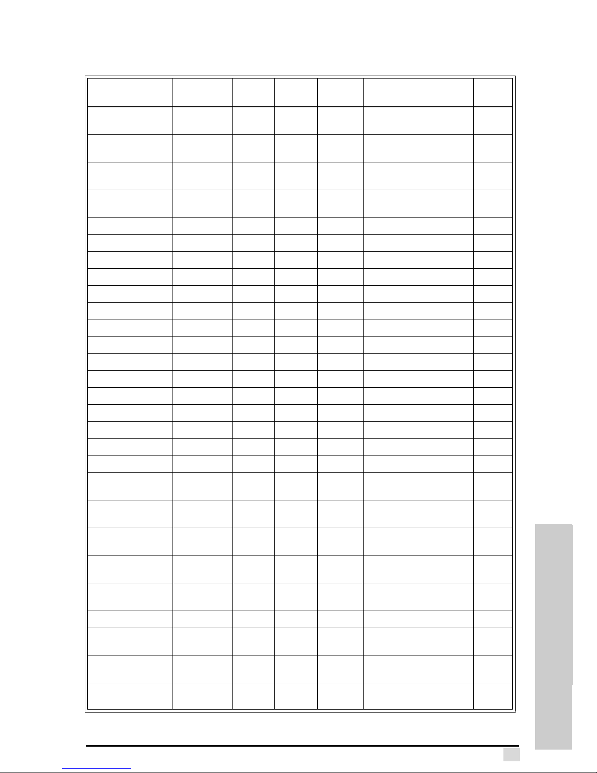
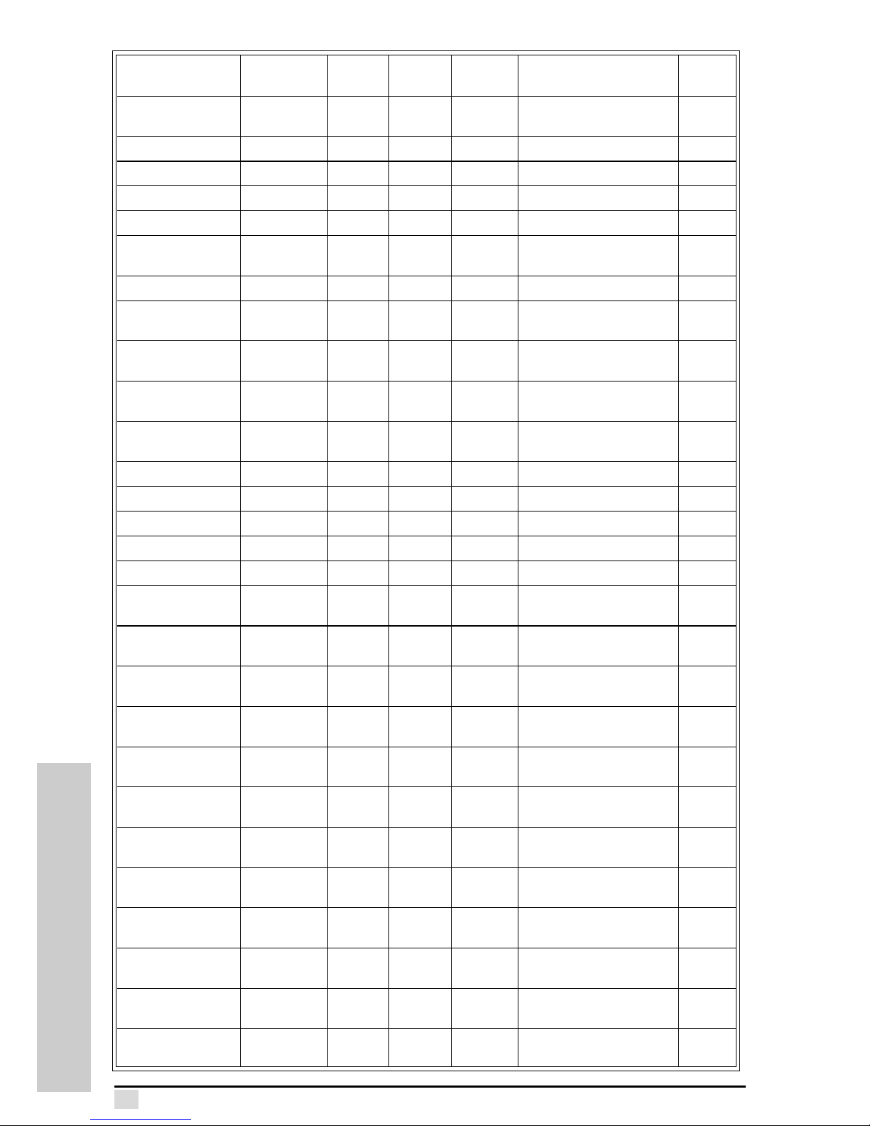
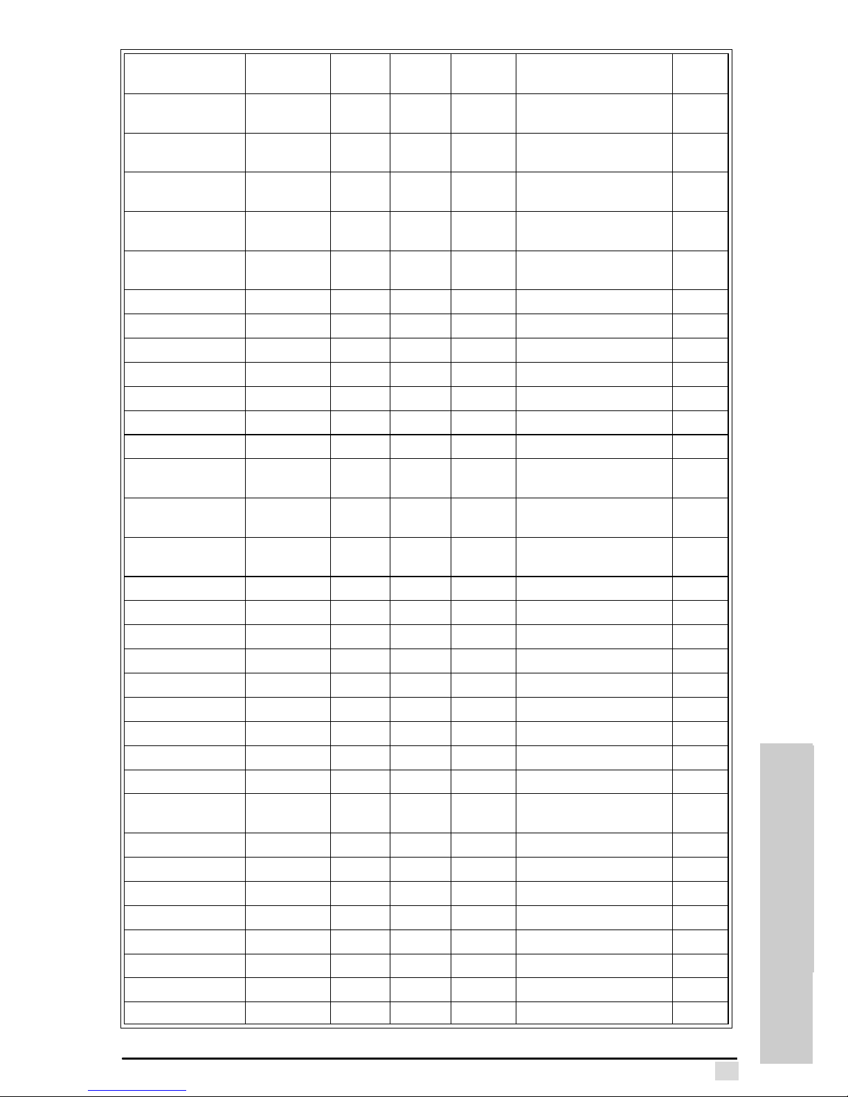
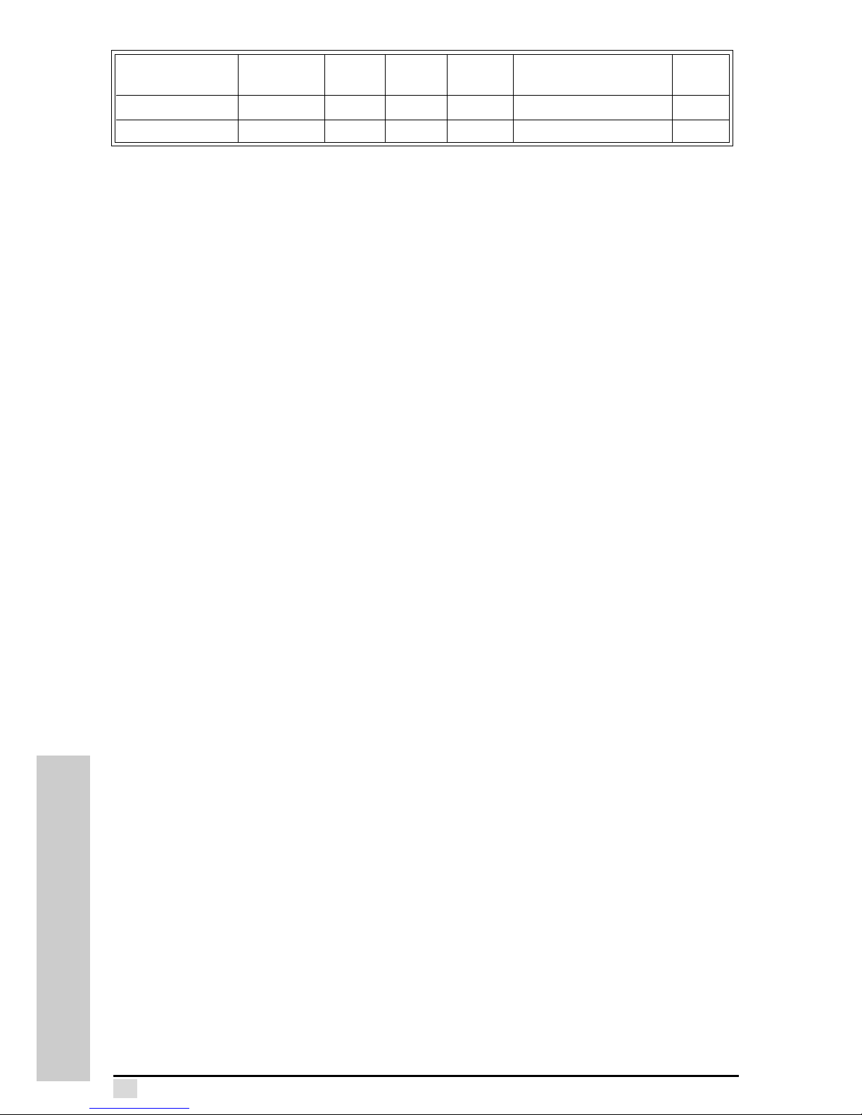
Command data chart
RS232 Control
Function
Command
Title
Min
Val ue
Max
Val ue
Default
Val ue
Example
Notes
Input signals-Write SIG 0 7 Component 1 YPbPr ==
SIG00
Component 1 RGB ==
SIG01
Component 2 YPbPr ==
SIG02
Component 1 RGB ==
SIG03
PC == SIG04
DVI == SIG 05
Composite == SIG06
S-Video == SIG07
Input Signals-Read SIG SIG??
Brightness-Write BRI 0 99 50 Brightness 50 == BRI50
Brightness-Read BRI BRI??
Contrast-Write CON 0 99 50 Contrast 50 == CON50
Contrast-Read CON CON??
Sharpness-Write SHA 0 11 5 Sharpness 5 == SHA50
Sharpness-Read SHA SHA??
Color-Write COL 0 99 62 Color 62 == COL62
Color-Read COL COL??
Tint-Write TIN 0 99 62 Tint 62 == TIN62
Tint-Read TIN TIN??
Color Temp-Write CTE 0 4 0 Color Temp 7800K ==
CTE00
Color Temp 5500K ==
CTE01
Color Temp 6500K ==
CTE02
Color Temp 9300K ==
CTE03
Color Temp User Mode ==
CTE04
Color Temp-Read CTE CTE
Color Temp UserWrite
CTU 0 99 0 Color Temp User 4000K ==
CTU00
Color Temp User 4100K ==
CTU01
Color Temp User 13900K
== CTU99
Page 65
Appendix E – RS-232 communication
56
RS-232 COMMUNICATION
color Temp UserRead
CTU CTU??
Gamma-Write TGA 0 7 3 Gamma 1.0 == TGA00
Gamma 1.5 == TGA01
Gamma 2.2 == TGA02
Gamma 2.8 == TGA03
Gamma User Mode ==
TGA04
Gamma-Read TGA TGA??
Color Mode-Write CMO 0 3 3 Color Mode Movie ==
CM000
Color Mode Sports ==
CM001
Color Mode VIvid ==
CM002
Color Mode Normal ==
CM003
Color Mode-Read CMO CMO??
Clock-Write CLO 0 99 50 Clock 50 == CLO50 PC Only
Clock-Read CLO CLO?? PC Only
Phase-Write HAS 0 31 0 Phase 0 == HAS PC Only
Phase-Read HAS HAS?? PC Only
Menu Picture Reset
MPR
MPR Menu Picture Reset ==
MPR00
OSD H PositionWrite
OPH 100 0 OSD H Position 0 ==
OPH00
OSD H PositionRead
OPH OPH??
OSD V PositionWrite
OPV 0 100 0 OSD V Position 0 ==
OPV00
Lamp Timer Reset
LTR
LTR Lamp Timer Reset Yes ==
LTR 01
Color Matrix RedWrite
CMR 0 30 30 Color Matrix Red 30 ==
CMG30
Color Matrix RedRead
CMR CMR??
Color Matrix GreenWrite
CMG 0 30 30 Color Matrix Green 30 ==
CMG30
Color Matrix GreenRead
CMG CMG??
Color Matrix BlueRead
CMB 0 30 30 Color Matrix Blue 30
==CMB30
Color Matrix BlueRead
CMB CMB??
Color Matrix CyanRead
CMC 0 30 30 Color Matrix Cyan 30
==CMC30
RS232 Control
Function
Command
Title
Min
Val ue
Max
Val ue
Default
Val ue
Example
Notes
Page 66
Appendix E – RS-232 communication
57
RS-232 COMMU-
RS-232 COMMUNICATION
Color Matrix CyanRead
CMC CMC??
Color Matrix
Magenta-Read
CMM 0 30 30 Color Matrix Magenta 30
==CMM30
Color Matrix
Magenta-Read
CMM CMM??
Color Matrix YellowRead
CMY 0 30 30 Color Matrix Yellow 30
==CMY30
Color Matrix YellowRead
CMY CMY??
Standby Mode-Write STM 0 1 1 Theater Bright == THM00
Theater Normal == THM01
Theater Mode-Read THM THM??
TimeOut-Write TIO 0 100 40 TimeOut40 == TIO40
TimeOut-Read TIO TIO??
Blending-Write BLE 0 4 0 Blending 0 == BLE00
Blending-Read BLE BLE??
OSD BackgroundWrite
OPA 0 2 0 OSD Background 0 ==
OPA00
OSD BackgroundRead
OPA OPA??
Menu Advanced
Reset
MAR enu Advanced Reset ==
MAR00
H-KeyStone-Write HKS 0 40 20 H-KeyStone 0 == HKS00
H-KeyStone-Read HKS HKS??
V-KeyStone-Write VKS 0 14 7 V-KeyStone 0 == VKS00
V-KeyStone-Read VKS VKS??
Projection-Write TAB 0 3 0 Front Tabletop == TAB00
Front Ceiling == TAB01
Rear Tabletop == TAB02
Rear Ceiling == TAB03
Projection-Read TAB TAB??
Menu Geometry
Reset
MGR Menu Geometry Reset ==
MGR00
Aspect Ratio-Write ASP 0 4 0 English == LAN00
Espanola == LAN01
Deutsch == LAN02
Francois == LAN03
Italiano == LAN04
Language-Read LAN LAN??
Factory Default DEF Factory Default == DEF00
Power On ONN Power On == ONN00
RS232 Control
Function
Command
Title
Min
Val ue
Max
Val ue
Default
Val ue
Example
Notes
Page 67
Appendix E – RS-232 communication
58
RS-232 COMMUNICATION
Power Off OFF Power Off == OFF00
Lamp Timer-Read LTM LTM??
RS232 Control
Function
Command
Title
Min
Val ue
Max
Val ue
Default
Val ue
Example
Notes
Page 68
 Loading...