

User’s and operator’s manual for art. 9801
Manuale d’uso e dell’operatore per art. 9801

Safety informations page 1
Precauzioni di sicurezza
Technical features page 4
Caratteristiche tecniche
Mains supply connection page 5
Collegamento fonte di alimentazione
Lamp installation, replacement and setting page 6
Inserimento, sostituzione e regolazione lampada
DMX signal connection page 9
Collegamento segnale DMX
Automatic functioning page 11
Funzionamento automatico
Appendix “A” (DMX values) page 14
Appendice “A” (valori DMX)
Appendix “B” (games list) page 13
Appendice “B” (lista giochi)
Components and parts page 16
Parti componenti
Technical drawings page 17
Disegni tecnici
Printed circuit and electric diagrams page 20
Circuiti stampati e schemi elettrici
Troubleshooting page 27
Risoluzione guasti
System board connection page 31
Connessioni scheda logica
INDEX • INDICE
ita
WARNING
!
INFORMAZIONI DI SICUREZZA
LEGGERE ATTENTAMENTE TUTTI GLI AVVERTIMENTI PRIMA DI COMPIERE QUALUNQUE OPERAZIONE SU QUESTO APPAREC-
CHIO. ISTRUZIONI PER PREVENIRE LESIONI O DANNI DOVUTI AL FUOCO, ALLE SCOSSE ELETTRICHE, AI RAGGI ULTRAVIOLET-
TI ED AI RISCHI MECCANICI.
1) Questo apparecchio è progettato per funzionare esclusivamente con lampade: MHD 1800W.
NON USARE ASSOLUTAMENTE ALTRI TIPI DI LAMPADA!
2) Mantenere la distanza minima di 0.5 metri da pareti ed altre superfici infiammabili.
3) Mantenere la distanza minima di 5.0 metri dagli oggetti illuminati.
4) Sostituire i fusibili solo con altri dello stesso tipo e valore.
5) Non installare il faro vicino fonti di calore. Non appoggiare il cavo di connessione sul faro quando questo è caldo.
•PROTEZIONE CONTRO SCOSSE ELETTRICHE
1) Questo apparecchio necessita di messa a terra.
2) Apparecchio di Classe I. Il conduttore di protezione deve far parte del cavo di alimentazione. Vedere pag. 5, fig. 1.
3) Per la connessione all’alimentazione principale procedere come in fig.1 a pagina 5. L’apparecchio deve essere protetto da un
interruttore differenziale In=16A Id= 0.03A (230VAC)
4) Disconnettere l’alimentazione prima di sostituire la lampada o aprire l’apparecchio. (personale di servizio).
•PROTEZIONE CONTRO RISCHI MECCANICI
1) Usare la catena di sicurezza supplementare quando installate il faro.
2) Rischio di esplosione con lampada calda. Non aprire l’apparecchio per 300 secondi dopo lo spegnimento.
3) La temperatura dell’apparecchio può raggiungere 100°C. Attendere circa 5 minuti prima di operare sul faro.
4) Sostituire la lampada se è danneggiata o deformata a causa del calore.
•PROTEZIONE CONTRO RISCHI DA RADIAZIONE UV
1) Non accendere l’apparecchio senza lo schermo protettivo o se le lenti o i filtri per l’ultravioletto sono danneggiate.
2) Gli schermi di protezione, le lenti, o i filtri ultravioletti, devono essere sostituiti se sono visibilmente danneggiati e se la loro
efficacia è stata ridotta, per esempio, da fessure o incisioni profonde.
3) Non guardare direttamente la lampada quando questa è accesa.
IMPORTANTE
!
SAFETY INFORMATION
READ ALL CAUTIONS AND WARNINGS PRIOR TO OPERATE THIS EQUIPMENT.
INSTRUCTION TO PREVENT INJURY OR DAMAGE DUE TO ELECTRIC SHOCK, FIRE, MECHANICAL HAZARDS AND UV
RADIATION HAZARDS.
• PROTECTION AGAINTS FIRE
1) This equipment is designed for use with the following lamps only: MHD 1800W.
DO NOT USE ANY OTHER TYPE LAMP!
2) Maintain minimum distance of 0.5 meter from walls or any other type flammable surfaces.
3) Maintain minimum distance to lighted objects of 5.0 meter.
4) Replace fuses only with the specified type and rating.
5) Do not install the spot close to heat sources. Do not lay the connection cable on the spot when it is warm.
• PROTECTION AGAINST ELECTRIC SHOCK
1) This equipment must be earthed.
2) Class I equipment. The power supply cord includes a protective earthing conductor as part of the cord. See page 5, pict.1a.
3) For connection to the supply mains proceed as pict.1 page 5. The equipment must be connected to branch circuit having a
circuit- breacker In=16A Id=0.03A (230VAC)
4) Disconnect power before lamp’s replacement or servicing (service personnel).
• PROTECTION AGAINST MECHANICAL HAZARDS
1) Use secondary safety chain when fixing this equipment.
2) Hot lamp explosion hazard. Do not open the equipment for 300 seconds after switching off.
3) Equipment surface may reach temperature up to 100°C. Allow about five minutes before handling.
4) Replace the lamp if it is damaged or thermally deformed.
• PROTECTION AGAINST UV RADIATION HAZARDS
1) Do not start on this equipment without lamp enclosure or if the protection screens, or ultraviolets screens are damaged.
2) The protection screens, the lenses, or the ultraviolet filters must be replaced if they are visibly damaged and their effectiveness
has been reduced, for example, by cracks or deep scratches.
3) Do not look directly at the lamp while lamp is on.
... 1 ...
eng

INTRODUZIONE
Il CITYCOLOR grazie ad un sistema ottico estremamente efficiente (brevetto internazionale n. WO99/40361), genera un potente
fascio di luce che può assumere innumerevoli tonalità di colore. Le prestazioni, in termini di luminosità e superficie illuminata,
raggiungono livelli inimmaginabili.
Il CITYCOLOR viene prodotto in due versioni:
• Art. 9801 CITYCOLOR per lampada a scarica MHD 1800W.
Il CITYCOLOR può lavorare in modo automatico o in modo sincrono, oppure può essere gestito da una unità di controllo esterna.
Il protocollo di ingresso è il DMX 512. Per il pilotaggio del CITYCOLOR raccomandiamo l’utilizzazione della nostra centralina DMX
Control Spot, della Control Show 512 oppure della Easy Control.
Per ottenere il meglio delle prestazioni ed un corretto funzionamento negli anni di questa unità, Vi consigliamo di leggere attentamente questo manuale prima di collegarla e metterla in uso. In questo modo acquisirete familiarità con i sui comandi e collegamenti
affinché possiate facilmente utilizzarla.
eng
ita
... 2 ...
INTRODUCTION
The CITYCOLOR projects, thanks to an extremely efficient optic system (international patent n. WO99/40361), a powerful light beam
which can create numberless color shades. Its performances, in terms of luminousity and lighted surfaces, can reach incredible
levels.
The CITYCOLOR comes in two versions:
• Art. 9801 CITYCOLOR for MHD 1800W discharge lamp.
The CITYCOLOR can work in automatic mode or in sincro mode, otherwise may be controlled by 8 bit DMX controllers
The input protocol is the DMX 512. To drive the CITYCOLOR we suggest to use either our controller DMX Control Spot, the
Control Show 512 or the Easy Control.
To make the most of its possibilites and for a correct functioning of this unit in the years to come, we suggest you to read carefully
this manual before connecting or putting the spot into use. By doing so you will gain experience with its commands and connections
and you will be easily able to use it.

... 3 ...
eng
ita
VOSTRA REFERENZA
Citate il numero del modello e di serie ogni volta che Vi rivolgete al vostro rivenditore per informazioni o assistenza.
CONFEZIONE BASE
La confezione base del proiettore CITYCOLOR contiene:
•Proiettore
•N. 2 riflettori piani “C”
•Manuale d’uso
•Garanzia Studio Due
•Connettore alimentazione
Disponibile su richiesta:
•Alette paraluce
•Lampada
Controllate che l’apparecchio non abbia subito alcun danno durante il trasporto.
Se avesse subito dei danni o se non dovesse funzionare, rivolgetevi al vostro rivenditore. Se l’apparecchio vi è
stato spedito, rivolgetevi immediatamente alla ditta di trasporto. Solo il destinatario (la persona o ditta
ricevente l’apparecchio) può reclamare per questo tipo di danni.
Check that the spot has not been damaged during transport. If it has been damaged or it does not work,
address the seller. Whether the spot has been shipped to you, please contact the shipping company.
Only the consignee (person or company) can claim for these damages.
WARNING
!
YOUR REFERENCE
Always remeber to give the serial number and to specify the model any time you address the seller for information or assistance.
BASIC KIT
The basic kit of the CITYCOLOR flood projector consists of:
•Projector
•N. 2 plane reflectors “C”
•User’s manual
•Studio Due warranty
•Input connector
Available on request:
•Barn doors
•Lamp
IMPORTANTE
!

... 4 ...
eng
ita
CARATTERISTICHE TECNICHE
•LAMPADA
A scarica MHD 1800W
Posizione di funzionamento: Orizzontale (±15°)
•COLORI
CYM cambiacolori a variazione continua (256 passi)
•DIMMER
0-100% a variazione continua (256 passi)
•POWER INPUT
Tensione nominale: 230Vac 50/60Hz
Su richiesta: 208Vac 60Hz; 200Vac 50Hz
Potenza nominale: 2000W
Corrente nominale: 10A (230Vac)
TECHNICAL FEATURES
•LAMP
Discharge MHD 1800W
Burning position: Horizontal (±15°)
•COLOURS
CYM color mixing continuously variable (256 steps)
•DIMMER
0-100% continuously variable (256 steps)
•POWER INPUT
Rated voltage: 230Vac 50/60Hz
On request: 208Vac 60Hz; 200Vac 50Hz
Rated power: 2000W
Rated current: 10A (230Vac)

... 5 ...
eng
ita
PRIMA DELL’USO
Leggere attentamente le istruzioni a pagina 1 prima di installare l’apparecchio. In particolare leggere quanto segue:
1) Disconnettere l’alimentazione prima di sostituire la lampada o effettuare la manutenzione (personale di servizio).
2) Non aprire il coperchio della lampada per 300 secondi dopo lo spegnimento.
3) Indossare guanti ed occhiali di protezione per sostituire la lampada o per lavorare all’interno del faro (personale di servizio).
Prima di connettere l’apparecchio: assicurarsi che la tensione e la frequenza di esercizio corrispondano ai valori indicati sull’etichetta.
• Il CITYCOLOR può essere fornito per una tensione di lavoro di 230VAC, 50 o 60 Hz
su richiesta: 208Vac, 60Hz; 200Vac, 50Hz
Per un’alimentazione di 100-120V è assolutamente necessario un auto trasformatore con le seguenti caratteristiche:
• Tensione d’uscita 230V
• Corrente d’uscita 10A
La connessione dell’unità alla rete è descritta in fig.1a. Per la connessione all’alimentazione principale procedere come in fig.1 a
pagina 5. L’apparecchio deve essere protetto da un interruttore differenziale In=16A • Id= 0.03A (230VAC)
a) Evitare di installare l’apparecchio in prossimità di fonti di calore. Distanziare gli apparecchi di almeno 1.5 metri. Non appoggiare
il cavo di collegamento sull’apparecchio caldo.
b) L’unità deve trovarsi in una posizione che ne permetta l’areazione. Evitare di ostruire le griglie di entrata e uscita dell’aria.
c) L’unità deve inoltre distare almeno 50 cm. da pareti o altre superfici infiammabili.
d) L’unità deve distare almeno 5 metri dagli oggetti illuminati.
Temperatura sulle superfici esterne dell’apparecchio:
• Dopo 5 minuti di funzionamento; Tc=75°C.
• Quando e’ stato raggiunto l’equilibrio termico; Tc=100°C.
IMPORTANTE
!
BEFORE USING
Read all cautions and warnings to page 1 prior to install this equipment. Particularly, read the follow:
1) Disconnect power before lamp’s replacement or servicing (service personnel)
2) Do not open the lamp cover for 300 seconds after switching off
3) Wear gloves and goggles to re-lamping or to work inside the unit (service personnel)
Before connecting the equipment to the power system: make sure that the mains voltage and frequency correspond to rated values.
• The CITYCOLOR can be equipped for a mains voltage 230VAC, 50 or 60Hz
on request: 208Vac, 60Hz; 200Vac, 50Hz
For a power supply of 100V-120V it is necessary to use one auto transformer with the following features:
• Output voltage 230V
• Output current 10A
The power supply cords construction is shown in pict.1a. For connection to the mains supply proceed as pict.1 page 5.
The equipment must be connected to branch circuit having a circuit-breacker In=16A • Id=0.03A (230VAC)
a) Do not install the spot close to the heat sources. Observe minimum distance between the spots of 1.5 meters. Do not lay the
connection cable on the spot when it is warm.
b) This unit must be positioned as to allow its ventilation. Be careful not to acclude the in-out ventilating grilles.
c) The unit must be positioned at least 50cm. from walls or other flammable surfaces.
d) Observe minimum distance to lighted objects of 5 meters.
External surface temperature:
• After 5 minutes work; Tc=75°C.
• Once the thermic balance has been obtained; Tc=100°C.
The equipment must be earthed.
IP 33 grade: the equipment must be installed on the horizontal plane.
WARNING
!
pict./fig.1a
IP 67
3 PIN CONNECTOR FOR POWER INPUT/
CONNETTORE 3 POLI PER L’INGRESSO
RETE ALIMENTAZIONE
pict./fig.1
L’apparecchio necessita di messa a terra.
IP 33: per garantire il grado di protezione indicato, l’apparecchio
deve essere installato sul piano orizzontale.
L = LIVE / FASE
N = NEUTRAL / NEUTRO
= EARTH / TERRA
... 6 ...
eng
ita
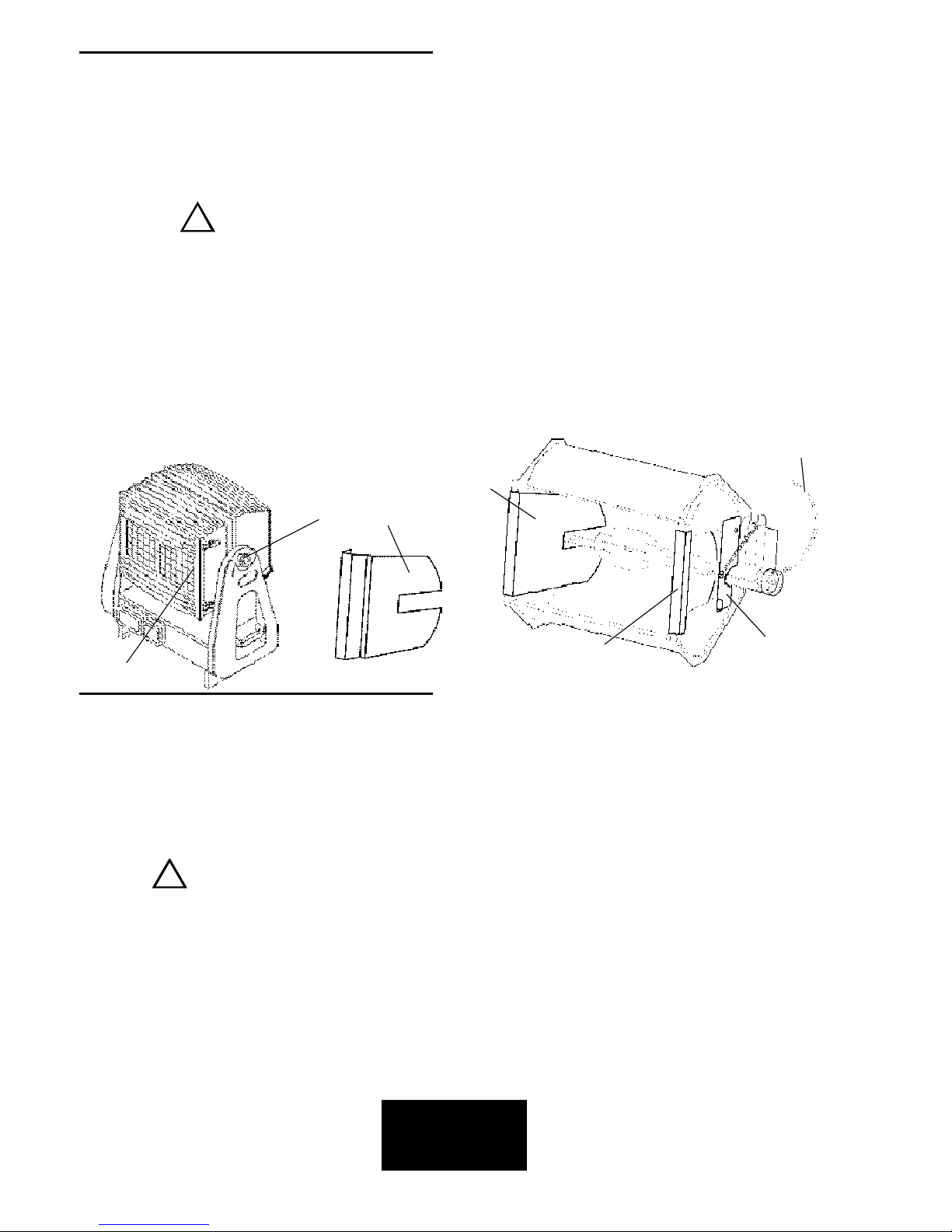
INSTALLAZIONE LAMPADA A SCARICA MHD 1800W
(vedere fig.2)
1) Disconnettere l’apparecchio prima di sostituire la lampada. Indossare guanti ed occhiali di protezione
2) Togliere completamente i pomelli laterali (A) sulla staffa che servono a bloccare la rotazione della testa
3) Aprire le due chiusure a scatto localizzate sul vano lampada dietro la staffa e togliere tutto il gruppo cambiacolori (G)
4) Togliere i due riflettori laterali (C1) o (C)
5) Sollevare i due portalampada superiori (D)
6) Collegare i fili (E) alle due estremità della lampada ed inserirla avendo cura di posizionare la protuberanza verso il riflettore
Non toccare il bulbo della lampada con le dita. Se questo avviene pulirlo con un panno asciutto ed alcool.
7) Abbassare i due portalampada superiori (D)
8) Rimettere i riflettori laterali. Per ottenere un’ottica più ampia utilizzare i riflettori sagomati C1. Per un’ottica più stretta i
riflettori piani C
9) Rimettere il gruppo cambiacolori (G) e fissare le quattro chiusure a scatto (B)
10)Inserire nuovamente i due pomelli laterali (A)
In caso di cambio lampada o manutenzione, non aprire mai l’apparecchio
se non sono trascorsi almeno 5 minuti dopo lo spegnimento.
Questa operazione deve essere effettuata con l’apparecchio scollegato
dalla rete di alimentazione
IMPORTANTE
!
4) Gli schermi di protezione, le lenti o i filtri per l’ultravioletto devono essere sostituiti se sono visibilmente danneggiati al punto che
la loro efficacia ne sia diminuita, per esempio da fessure o incisioni profonde.
5) La lampada deve essere sostituita se essa e’ stata danneggiata o deformata dal calore.
6) Pulire periodicamente le griglie di entrata e uscita dell’ aria.
7) Non maneggiare l’apparecchio prendendolo dalla testa, ma sempre dalle apposite maniglie.
4) The protection screens, the lenses, or the ultraviolet filters must be replaced if they are visibly damaged and their effectiveness
has been reduced, for example, by cracks or deep scratches.
5) The lamp must be replaced if it has been damaged or thermally deformed.
6) Clean regularly the in-out ventilating grilles.
7) Do not handle the spot by taking it by the head, but always by using the special handles.
INSTALLATION OF THE DISCHARGE LAMP MHD 1800W
(see pict.2)
1) Disconnect power before lamp’s replacement. Wear gloves and goggles.
2) Remove completely the lateral pommels (A) on the bracket which are used to stop the head rotation
3) Open the two spring-locks located on the lamp box behind the bracket and take off the whole changecolor unit (G)
4) Remove the two lateral reflectors (C1) or (C)
5) Lift up the two lampholder (D)
6) Connect the cables (E) to the two ends of the lamp, taking care that protuberance of the bulb is set towards the reflector
Do not touch the quarz bulb with fingers. If this happenes, clean the bulb before use with dry cloth and alcohol.
7) Put down the two upper lampholder (D)
8) Put in again the two lateral plane reflectors. To obtain a wider optic (beam) use the C1 shaped reflectors. For a narrow optic
(beam) use the C flat reflectors.
9) Put in again the changecolor unit (G) and fix the four spring-locks (B)
10)Connect again the two lateral pommels (A)
In case of replacement of the lamp or maintenance, do not open
the fixture unless 5 minutes have passed from the switching off.
This operation has to be done when the apparatus is disconnected from
the mains supply
WARNING
!
A
pict./fig.2
C1
C
D
E
C
G

eng
ita
PANNELLINO DI CONTROLLO
Sul pannellino di controllo del CITYCOLOR (fig.3) oltre il display che indica l’assegnazione dei canali, si trovano anche un LED ed i
microswitches per il controllo e pilotaggio del faro.
Diamo di seguito una breve spiegazione delle varie funzioni del pannellino di controllo:
LED
•Led “DMX-RX” ACCESO: Indica che il segnale d’ingresso DMX è presente
SPENTO: Indica che il segnale d’ingresso DMX è assente
PULSANTE RESET
Permette di effettuare il resettaggio locale di tutte le funzioni del faro
COMMUTATORI ROTATIVI
•H = Centinaia
•D = Decine (permette anche la scelta dei giochi; vedere pag. 11-12 e 13).
•U = Unità (permette anche la scelta dei giochi; vedere pag. 11-12 e 13).
CONTROL PANEL
On the control panel of the CITYCOLOR (pict.3), besides the display showing the DMX channel assignment, one can also find a led
and the microswitches which enable the control and driving of the spot.
Here below we shortly explain the different functions of the control panel:
LED
•Led “DMX-RX” ON: The DMX signal is present
OFF: There is no DMX signal
RESET KEY
It enables to execute the local reset of all functions of the spot
ROTATIVE SWITCHES
•H = Hundreds
•D = Tens (it also enables to choose the games; see page 11-12 and 13)
•U = Units (it also enables to choose the games; see page 11-12 and 13)
pict./fig.3
... 7 ...
H
D
U
... 8 ...
eng
ita
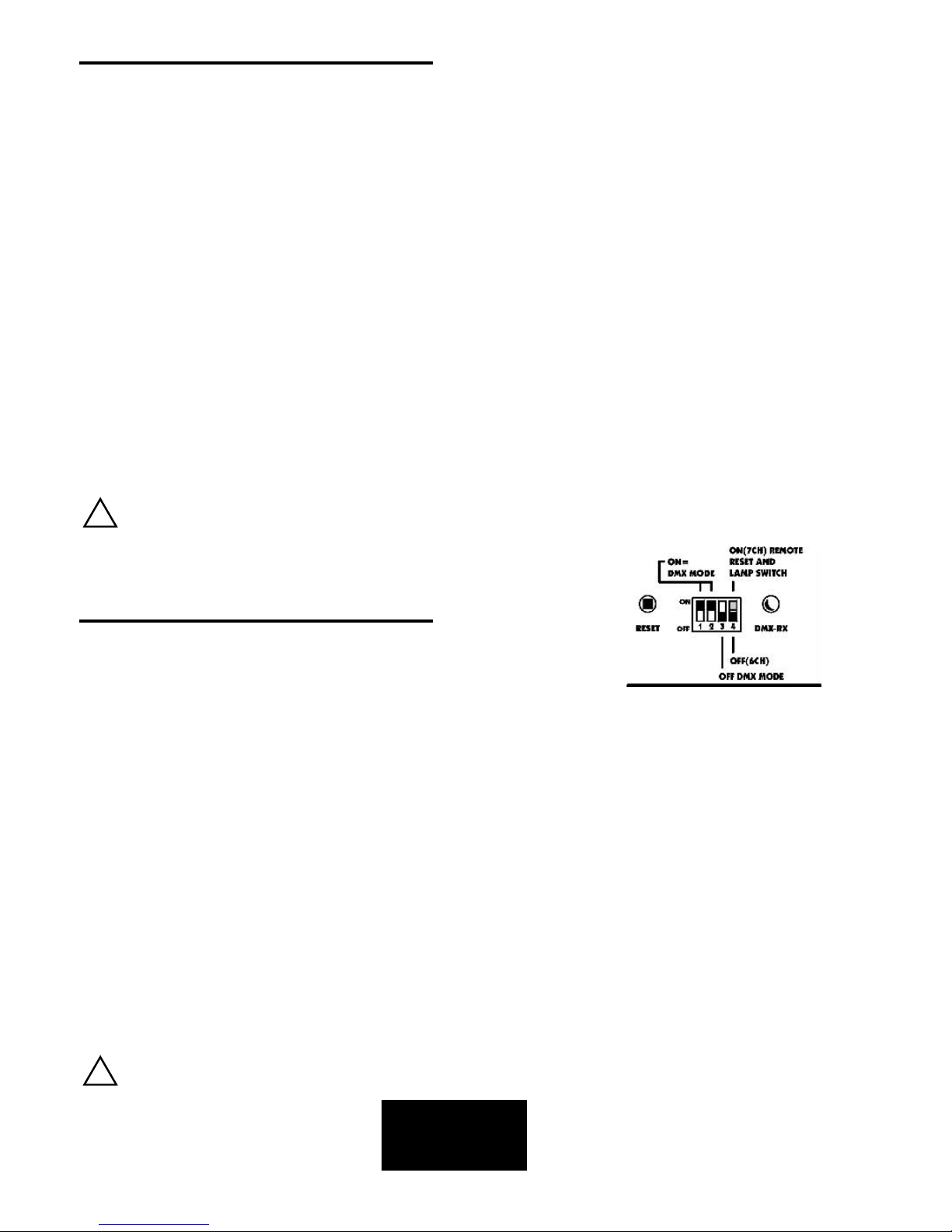
PILOTAGGIO DEL CITYCOLOR CON CENTRALINA DMX
• Settare i quattro dip switches come in fig.4:
Switch n.1=ON
Switch n.2=ON
Switch n.3=OFF
Switch n.4=ON (se si vuole attivare il canale 7 che permette il resettaggio dei motori e lo spegnimento della lampada dalla
centralina)
Switch n.4=OFF (se non si vuole attivare il canale 7)
• Selezionare il canale DMX desiderato agendo sui tre commutatori rotativi
• Effettuare il collegamento di segnale DMX tra centralina e faro
• Verificare che il led DMX-RX sia acceso (segnale DMX presente)
• Se non si ha segnale, effettuare un resettaggio manuale tramite il pulsante RESET localizzato sul faro
CANALI DMX
La lista completa dei valori DMX si trova nell’appendice “A”, pagina 14
Switch n.4=ON Switch n.4=OFF
CH 1= Speed CH 1= Speed
CH 2= Cyan CH 2= Cyan
CH 3= Yellow CH 3= Yellow
CH 4= Magenta CH 4= Magenta
CH 5= Dimmer CH 5= Dimmer
CH 6= Basic colors+rainbow CH 6= Basic colors+rainbow
CH 7= Reset/Lamp off
DRIVING THE CITYCOLOR WITH A DMX REMOTE CONTROLLER
• Set the four switches as in pict.4:
Switch n.1=ON
Switch n.2=ON
Switch n.3=OFF
Switch n.4=ON (if you want to activate channel 7 which enables the reset of the motors and the switching off of the lamp from
the controller)
Switch n.4=OFF (if you don’t want to activate channel 7)
• Select the requested DMX starting address by operating on the three rotative switches
• Connect the DMX signal between the fixture and the controller
• Check that the DMX-RX led is ON. (DMX signal present)
• If there is no signal, you must manually reset by operating on the RESET button located on the fixture
DMX CHANNELS
The complete list of the DMX values can be found in appendix “A”, page 14
Switch n.4=ON Switch n.4=OFF
CH 1= Speed CH 1= Speed
CH 2= Cyan CH 2= Cyan
CH 3= Yellow CH 3= Yellow
CH 4= Magenta CH 4= Magenta
CH 5= Dimmer CH 5= Dimmer
CH 6= Basic colors+rainbow CH 6= Basic colors+rainbow
CH 7= Reset/Lamp off
Per utilizzare il CYM, il canale n. 6, deve essere posto al valore DMX= 00
When using CYM color mixing, the basic colors channel # 6 must be set at: 00=DMX value
pict./fig.4
IMPORTANTE
!
WARNING
!

... 9 ...
eng
ita
CONNESSIONE SEGNALE (DMX 512)
La connessione del segnale DMX con il CITYCOLOR deve essere effettuata tramite i connettori ingresso segnale XLR 5 pin presenti
sul pannello laterale della base dell’apparecchio. (fig.5)
La nomenclatura dei pin dei connettori d’ingresso per la connessione con il segnale DMX è riportata nella tabella. (fig.5a)
Al fine di evitare problemi nella trasmissione del segnale è raccomandato l’utilizzo di un cavo adatto a trasmissioni dati ad alta
velocità.
In caso di linee con lunghezza totale oltre i 150-200 metri è consigliabile utilizzare un amplificatore di segnale. L’uso di un normale
cavo microfonico o audio è consigliabile soltanto per linee di lunghezza non superiore ai 100 metri.
CONNECTION THE DATA LINK (DMX 512)
The connection of the DMX signal to the CITYCOLOR must be made by using the signal input XLR 5 pin connectors which are
located on the control panel of the fixture. (pict.5)
The pin nomenclature of the connectors for the connection to the DMX signal is listed in the table. (pict.5a)
In order to avoid any problem in the signal transmission, it is warmly suggested to use a cable for high speed data transmission.
If the lines have a total length over 150-200 mts it is suggested to use a signal amplifier.
The usage of a normal microphonic or audio cable is suggested only for lines max 100 mts long.
pict./fig.5
pict./fig.5a
1
2
3
12
3

... 10 ...
eng
ita
TERMINALE LINEA DMX
L’incorretto o il mancato collegamento del terminale di linea è probabilmente la più comune causa del difettoso funzionamento
della linea DMX.
Il terminale di linea DMX consiste in una resistenza inserita tra i due pin “data” (pin 2 e 3) posta alla fine della linea.
La resistenza terminale dovrebbe avere idealmente lo stesso valore dell’impedenza del cavo di collegamento.
Suggeriamo di utilizzare un terminale con una resistenza da 100 ohm.
E’ raccomandato per tutti i sistemi DMX 512 inserire il teminale di linea nel connettore uscita DMX dell’ultimo
apparecchio collegato.
IMPORTANTE
DMX TERMINAL LINE
The wrong connection of the terminal line or its non-connection are probably the most frequent reasons for the defective functioning
of the DMX line. The terminator is a resistor fitted between the two “data” lines (pins 2 and 3 of an XLR 5 pin connector) at the end
of the cable furthest from the transmitter. The terminator resistor should have the same value as the impedance of the connection
cable.
We suggest to use a terminal with a 100 Ohm resistor.
It is recommanded that all DMX 512 systems have the termination resistor at the and of the line.
WARNING
DMX CONTROLLER OR LIGHT
CONSOLE
CENTRALINA O BANCO DMX
EXAMPLE 1/ESEMPIO 1
Connection controller-spot with 1 DMX 512 OUTPUT
Collegamento centralina-spot ad una sola LINEA DI USCITA DMX 512
TERMINATION RESISTOR
TERMINALE DI LINEA
LAST SPOT
ULTIMO SPOTSPOT
SPOT
SPOT
DMX CONTROLLER OR LIGHT
CONSOLE
CENTRALINA O BANCO DMX
TERMINATION RESISTOR
TERMINALE DI LINEA
LAST SPOT
ULTIMO SPOT
SPOT
EXAMPLE 2/ESEMPIO 2
Connection controller-spot to one DMX 512 OUTPUT over 150mts long
Collegamento centralina-spot ad una sola LINEA DI USCITA DMX 512 lunga oltre 150mt.
SIGNAL AMPLIFIER
AMPLIFICATORE
DI SEGNALE
LINE > 150mts (with microphonic or audio cable)
LINEA > 150mt (con cavo microfonico o audio)
!
!

eng
ita
FUZIONAMENTO AUTOMATICO DEL CITYCOLOR
1) Settare i quattro dip switches nel seguente modo:
MASTER (fig.6) SLAVE (fig.6a)
• Switch n.1=OFF ON
• Switch n.2=ON OFF
• Switch n.3=ON ON
• Switch n.4=OFF OFF
2) Agire sui tre commutatori rotativi (pag. 7) dell’apparecchio MASTER per impostare il gioco desiderato
(i giochi disponibili vanno da 1 a 15).
Il programma che cambia tutti i colori è il programma n.11
3) Premere il pulsante RESET
4) Attendere circa 30 secondi ed il faro comincerà ad eseguire la sequenza dei colori automatica
5) Nel caso si desideri sincronizzare più di un CITYCOLOR (vedi pag.13 MODO SINCRONO), predisporre il primo come MASTER
e gli altri SLAVE ed effettuare il collegamento con cavi usati per il DMX
AUTOMATIC FUNCTIONING OF THE CITYCOLOR
1) Set the four dip switches in this way:
MASTER (pict.6) SLAVE (pict.6a)
• Switch n.1=OFF ON
• Switch n.2=ON OFF
• Switch n.3=ON ON
• Switch n.4=OFF OFF
2) Operate on the rotative switches (page 7), on MASTER fixture, to set the requested games
(the available games go from 1 to 15).
Programme n.11 is the one which enables to change all the colors
3) Press the RESET button
4) Wait for about 30 seconds and the fixture will start to run the automatic color sequency
5) If you wish to synchronize more than one CITYCOLOR (see page 13 SYNCHRO MODE), set the first as MASTER and the
others as SLAVE and connect them by using standard DMX cables
... 11 ...
pict./fig.6 pict./fig.6a
MASTER SETTING SLAVE SETTING

... 12 ...
eng
ita
ESEMPIO DI PREDISPOSIZIONE IN MODO AUTOMATICO (1 APPARECCHIO)
• Il CITYCOLOR può lavorare in MODO AUTOMATICO:
1) Selezionare i dip switches come MASTER (fig.7)
2) Scegliere i giochi selezionando i numeri 1-15 (commutatori rotativi)
3) Premere il pulsante RESET
Una breve guida alla scelta dei giochi si trova all’appendice “B”, pagina 15
EXAMPLE OF AUTO MODE SETUP (1 FIXTURE)
• The CITYCOLOR can work in AUTO MODE:
1) Setting the dip switches as MASTER (pict.7)
2) Choose the games by setting the number 1-15 (rotative switches)
3) Press the RESET button
A short list of the games can be found in appendix “B”, page 15
pict./fig.7
ROTATIVE SWIT CHES/
COMMUTATORI RO TATIVI
AUTO MODE SELECTION
MASTER

I cavi sono gli stessi della connessione DMX
The cables are the same as DMX standard cable
IMPORTANTE
!
MASTER SETTING SLAVE SETTING
pict./fig.7a
MASTER SLAVE SLAVE SLAVE
SYNCHRO MODE CONNECTION
EXAMPLE OF SYNCHRO MODE SETUP (MORE THAN ONE FIXTURE)
• The CITYCOLOR can work in SYNCHRO MODE
1) Interconnect all the CITYCOLOR by using the standard DMX cables
2) Set the first CITYCOLOR as MASTER (transmitter) (pict.7a). Press the RESET button
3) It is possible to set up to 31 CITYCOLOR as SLAVE (receivers) (pict.7b). Press the RESET button
4) Choose the games by setting, on MASTER fixture, the number 1-15 (rotative switches)
A short list of the games can be found in appendix “B”, page 15
ESEMPIO DI PREDISPOSIZIONE IN MODO SINCRONO (PIU’ DI UN APPARECCHIO)
• I CITYCOLOR possono lavorare in MODO SINCRONO
1) Interconnettere tutti i CITYCOLOR con un cavo standard per collegamenti DMX
2) Settare il primo CITYCOLOR come MASTER (trasmettitore) (fig.7a). Premere il pulsante RESET
3) E’ possibile settare fino a 31 CITYCOLOR come SLAVE (ricevente) (fig.7b). Premere il pulsante RESET
4) Scegliere i giochi selezionando, sull’apprecchio MASTER, i numeri 1-15 (commutatori rotativi)
Una breve guida alla scelta dei giochi si trova all’appendice “B”, pagina 15
ita
eng
... 13 ...
WARNING
!
pict./fig.7b

... 14 ...
eng
ita
APPENDIX “A”
Here below you can find the complete list of DMX values (ref. page 8)
APPENDICE “A”
Diamo di seguito la lista completa dei valori DMX (rif. pag. 8)

... 15 ...
eng
ita
APPENDIX “B”
Here below you can find the complete list of the available games (ref. page 12 and 13)
APPENDICE “B”
Diamo di seguito la lista completa dei giochi disponibili (rif. pag. 12 e 13)

... 16 ...
SPARE PARTS, TECHNICAL DRAWINGS and SCHEMATIC DIAGRAMS

... 17 ...
•A / BASE•

... 18 ...
•B/HEAD 1•

... 19 ...
•B/HEAD 2•

... 20 ...
•TRAFOBCC (PC)•
•TRAFOBCC (DIAGRAM)•

... 21 ...
•CC251 (PC)•

... 22 ...
•CC251 (DIAGRAM)•

... 23 ...
•DMXCC (PC)•

... 24 ...
•DMXCC (DIAGRAM)•

... 25 ...
•ET1203CC (PC)•

... 26 ...
•ET1203CC (DIAGRAM)•

... 27 ...
eng
APPENDIX “C”
Table A1 • GENERAL TOUBLESHOOTING

... 28 ...
eng
APPENDIX “C”
Table A2 • DATA LINK TOUBLESHOOTING

... 29 ...
eng
APPENDIX “C”
GENERAL TOUBLESHOOTING

... 30 ...
eng
APPENDIX “C”
TRAFO BOARD and CC180 or CC250 (pict.2)

•POWER SUPPLY +26V Led
Lit up = Direct voltage, provided by TRAFO BOARD, is operating on the board.
Light out = Check connector, interconnecting cable and fuse on TRAFO BOARD.
•+5V Led
Lit up = Direct voltage provided by U2 (7805), is operating on the board.
Light out = Check U2 (7805) and R5 resistor. If the voltage regulator (7805) warm up and its output
voltage is 1÷2 V, that means there is a short circuit on PC BOARD and then replace ET1203.
•SIGNAL FROM DMX BOARD Led
Lit up = The serial signal is operating on the board.
Light out = Check the U1 (6N137) and interconnecting cable with DMX PC BOARD.
•STEPPER MOTOR channel not working: (exemple yellow)
1) Switch off the apparatus and disconnect the YELLOW and CYAN cables.
2) Connect YELLOW cable on CYAN OUTPUT.
3) Switch on the apparatus:
3a) If YELLOW motors work normally you must replace U9 (L6219).
3b) If the motors don’t work you can check the motors and the interconnecting circuit (cable and connectors).
Attn. to check cable and motors, you can measure the resistance as follow:
between PIN1 and PIN21 (on IC U9) R=18ohm; between PIN2 and PIN5 (on IC U9) R= 18ohm.
eng
APPENDIX “C”
Motors board (pict.3)
... 31...

Asia branch: STUDIO DUE (Far East) LTD
Unit D 29/F West Gate Tower 7
Wing Hong Street
Kln - Hong Kong
tel. +852/29542141
fax +852/23302515
The features on this brochure are not binding: they can be changed without notice.
Le caratteristiche riportate su questo catalogo non sono impegnative e possono
essere soggette a variazioni senza preavviso.
Head Office: STUDIO DUE Light Division s.r.l.
Str. Poggino, 100 - 01100 Viterbo (Italy)
tel. +39/0761/353902 • +39/0761/352520
fax +39/0761/352653
www.studiodue.com
Informations:
info@studiodue.com
Technical assistance:
service@studiodue.com
Rev • 2-07/00
 Loading...