

STUDIO DUE CityColor400 User Manual

Safety informations .......................................................................................................................... page 1
Technical features ............................................................................................................................. page 2
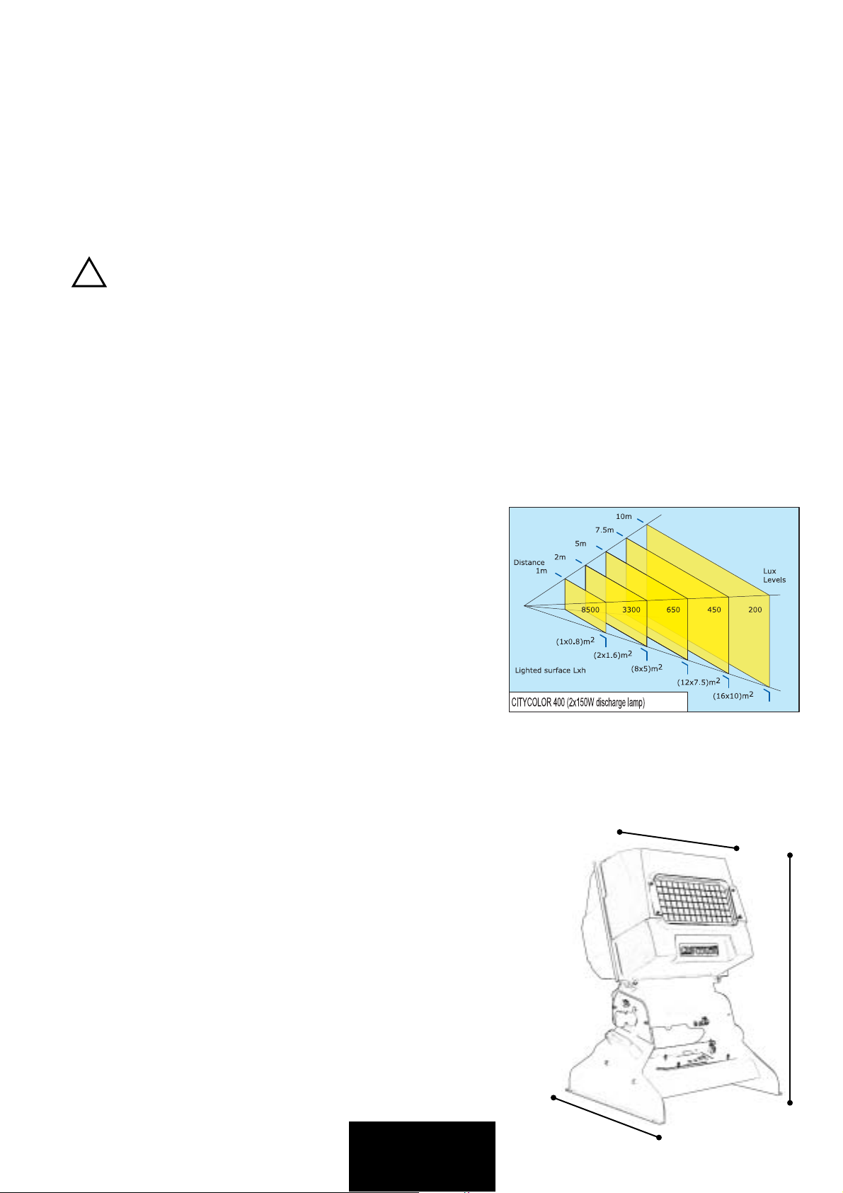
Photometric parameters .................................................................................................................. page 2
Before using ...................................................................................................................................... page 3
Main supply connection, DMX signal connection / fuses replacement ....................................... page 4
Lamp installation, replacement ....................................................................................................... page 5
Control panel and configuration .....................................................................................................page 6
Use of the CityColor 400 .................................................................................................................. page 6
DMX line and terminator .................................................................................................................. page 8
Automode functioning ..................................................................................................................... page 8
DMX channels assignment .............................................................................................................. page 9
Games table ...................................................................................................................................... page 10
Technical drawings, spare parts, electric diagrams ........................................................................page 11
ENGLISH INDEX
400

WARNING
!
SAFETY INFORMATION
READ ALL CAUTIONS AND WARNINGS PRIOR TO OPERATE THIS EQUIPMENT.
INSTRUCTION TO PREVENT INJURY OR DAMAGE DUE TO ELECTRIC SHOCK, FIRE, MECHANICAL HAZARDS AND
UV RADIATION HAZARDS.
• PROTECTION AGAINTS FIRE
1) This equipment is designed for use with the following lamp only: CDM-SA/T 150W/942 (PHILIPS)
DO NOT USE ANY OTHER TYPE LAMP!
2) Maintain minimum distance of 0.5 meter from walls or any other type flammable surfaces.
3) Maintain minimum distance to lighted objects of 5.0 meter.
4) Replace fuses only with the specified type and rating.
5) Do not install the spot close to heat sources. Do not lay the connection cable on the spot when it is warm.
• PROTECTION AGAINST ELECTRIC SHOCK
1) This equipment must be earthed.
2) Class I equipment. The power supply cord includes a protective earthing conductor as part of the cord.
3) For connection to the supply mains proceed as pict.2 page 4. The equipment must be connected to branch circuit having a
circuit- breacker In=16A Id=0.03A (230VAC)
4) Disconnect power before lamp’s replacement or servicing (service personnel).
• PROTECTION AGAINST MECHANICAL HAZARDS
1) Use secondary safety chain when fixing this equipment.
2) Hot lamp explosion hazard. Do not open the equipment for 300 seconds after switching off.
3) Equipment surface may reach temperature up to 100°C. Allow about five minutes before handling.
4) Replace the lamp if it is damaged or thermally deformed.
• PROTECTION AGAINST UV RADIATION HAZARDS
1) Do not start on this equipment without lamp enclosure or if the protection screens, or ultraviolets screens are damaged.
2) The protection screens, the lenses, or the ultraviolet filters must be replaced if they are visibly damaged and their effectiveness
has been reduced, for example, by cracks or deep scratches.
3) Do not look directly at the lamp while lamp is on.
INTRODUCTION
Thank you for choosing our CityColor400:
The fixture projects, thanks to an extremely efficient optic system (PATENT PENDING), a powerful light beam which can create numberless color shades. Its performances, in terms of luminousity and lighted surfaces, can reach incredible levels.
The CityColor400 comes in unique version:
• Art. 0302 CITYCOLOR400 for two CDM-T 150W discharge lamps
The fixture can work in automatic mode or in synchro mode, otherwise may be controlled by 8 bit DMX controllers
The input protocol is the DMX 512. To drive the fixture we suggest to use either our Control Show 512, Fancy or the Easy Control.
To make the most of its possibilites and for a correct functioning of this unit in the years to come, we suggest you to read carefully
this manual before connecting or putting the spot into use. By doing so you will gain experience with its commands and connections
and you will be easily able to use it.
... 1 ...
YOUR REFERENCE
Always remember to give the serial number and to specify the model any time you address the seller for information or assistance.
BASIC KIT
The basic kit of the CityColor400 flood projector consist of:
•Projector
•User’s manual
•Studio Due warranty
•Lamps (upon request)
WARNING
!
Check that the spot has not been damaged during transport. If it has been damaged or it does not work, address
the seller. Whether the spot has been shipped to you directly, please contact the shipping company.
Only the consignee (person or company) can claim for these damages.
TECHNICAL FEATURES (CITYCOLOR 400 discharge lamp • art. 0302)
• LAMP
2x MasterColour CDM-SA/T 150W/942 (PHILIPS)
Color temperature: 4.200 °K
Average lamp life: 6.000 hours
Luminous flux: 2 x 14.000 lm
Burning position: Universal
• OPTIC COLOUR SYSTEM
Full CYM color mixing,unlimited variety of colours and shades
High resolution stepper motors
• DIMMER
0-100% continuously variable (256 steps)
• BEAM ANGLE
Beam angle (50%):45 °
• IP RATE
IP 66
• CONTROL INPUT
Standard interface: RS-485;opto-couplet input
Protocol:USITT DMX 512
• AUTOMODE
Stand-alone control: auto mode function master/slave (synchro mode) with 27 programs
• POWER SUPPLY
Rated voltage: 200-208-230-240; 50Hz. On request: 60Hz
Rated power: 500Va
Rated current: 2,2A (230V)
• POWER FACTOR CORRECTOR
built-in cos Ø 0.9
510 mm
• FUSES
Lamp fuse: 5.0A/250V (delay time)
Electronic fuse: 2.0A/250V (delay time)
• DIMENSION (WxDxH)
mm 510x490x720
• WEIGHT
Kgs. 31,0
720 mm
490 mm
... 2 ...

BEFORE USING
CITYCOLOR400 art. 0302
230 V;2.24A; 50-60 Hz
AC
Ta 45°C
Tc
100°C
IP 66
LAMP CDM-T 150W G12
MAIN FUSE
ELEC. FUSE
The equipment must be earthed.
IP 66 rate: to ensure the declared IP rate choose the correct size of the cables
WARNING
!
(DMX cables: size form 3 to 6.5 mm - Main Power cables: size from 6 to 12 mm).
All the gaskets and the glass must be keeped in full working order.
If the fixture is not connected with DMX cables DON'T REMOVE the green protection.
Read all cautions and warnings to page 1 prior to install this equipment. Particularly, read the follow:
1) Disconnect power before lamp’s replacement or servicing (service personnel)
2) Do not open the lamp cover for 300 seconds after switching off
3) Wear gloves and goggles to re-lamping or to work inside the unit (service personnel)
4) The equipment must be connected to branch circuit having a circuit-breacker In=16A • Id=0.03A (230VAC)
5) Make sure that the main voltage and frequency correspond to rated values on the data label, pict.1.
If is necessary set-up the red connector to the right position, pict.1a/1b
Before any operation on the fixture
a) Do not install the spot close to the heat sources. Do not lay the connection cable on the spot when it is warm.
b) This unit must be positioned as to allow its ventilation.
c) The unit must be positioned at least 1 m from walls or other flammable surfaces and minimum 5 meters to lighted objects.
-External surface temperature Ta 45°C:
• After 5 minutes work; Tc=75°C.
• Once the thermic balance has been obtained; Tc=100°C.
d) Replace the lamp when is exhausted (6000 h) to avoid bad peformances of the fixture or that the optic system is damaged by
the lamp explosion. It must be replaced if it has been damaged or thermally deformed
e) The protection screens, the lenses, or the ultraviolet filters must be replaced if they are visibly damaged and their effectiveness
has been reduced, for example, by cracks or deep scratches.
f) In case of installation of the spot to a truss, check carefully that the fixture is fixed with a chain to both truss and unit.
g) Do not handle the spot by taking it by the head, but always by using the handles.
240V
230V
®
CITYCOLOR400 art. 0302
Disconnect the unit from power before replacing the lamp or servicing
LAMP CDM-T 150W G12
1m
pict.1
Do not open for 300 seconds after the switching off.
CAUTION:
Ta 45°C
Tc 100°C
Very hot lamp
INSIDE
T5A
IP 66
MAIN FUSE
• EXPLOSION HAZARD •
230 V ; 2.24A; 50-60 Hz
AC
T2A
ELEC. FUSE
SN
QC
230V
240V
pict.1a
pict.1b
... 3 ...
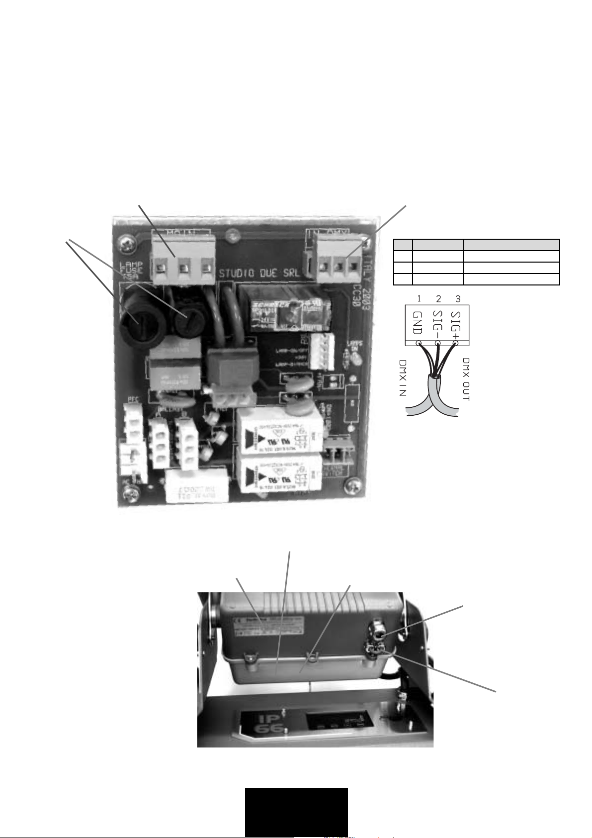
MAIN POWER AND DMX CONNECTION
1) Disconnect power before lamp’s replacement or servicing (service personnel)
1) Open the rear box cover.
• The fixture can be equipped for 200/208/230/240Vac, 50Hz main voltage (pict.1a/1b). On request 60Hz.
3) Insert the main power cable into the PG (pic.3), connect the cable to the main power connector (pic2) and tighten the PG.
3) If necessary (synchro-mode), insert the the DMX cables into the PG (pic.3), connect the cables to the DMX connector (pic2)
and tighten the PG.
4) Close the box cover with care, pict.3.
MAIN POWER CONNECTOR
N=NEUTRAL - GND=HEART -PH=LIVE
FUSES
DMX CONNECTOR
PIN WIRE SIGNAL
1 SHIELD GROUND/RETURN/OV
2 INNER CONDUCTOR DATA COMPLEMENT ( -, INVERTED)
3 INNER CONDUCTOR DATA COMPLEMENT ( -, NOT INVERTED)
pict.2
pict.3
DATA LABEL
BOX COVER
CONNECTION BOARD (pict.2)
... 4 ...
INSIDE THE BOX
MAIN POWER PG
CABLE SIZE Ø 6 - 12mm
DMX PG
CABLE SIZE Ø 3 - 6.5mm
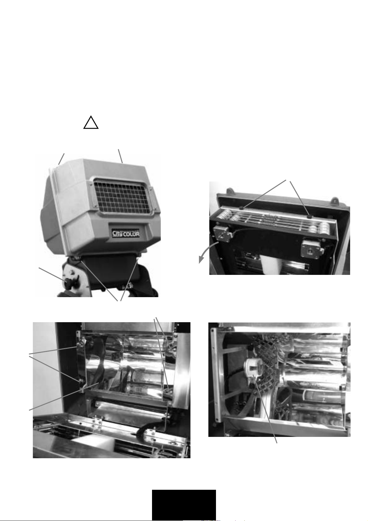
LAMP'S INSTALLATION OR REPLACEMENT
1) Disconnect power before lamp’s replacement. Wear gloves and goggles.
2) Tighten the two pommels (P) and lock the fixture's head as shown in pict.4
3) Unscrews the 4 screws (A) and remove the head cover, pict.4
4) Remove the nuts (S) to the dichroic group and open it with care, pict.5
5) Unscrews the screws (S1) and remove the two lateral reflectors (C1), pict.6
6) Insert the lamp into the lampholder (D) and repeat this procedure for the other lamp, pict.7
Do not touch the quarz bulb with fingers. If this happenes, clean the bulb before use with dry cloth and alcohol.
7) Replace the two lateral reflectors (C1) and fix it with screws (S1)
8) Close the dichroic group with the nuts (S)
9) Put in again the head cover and screw the 4 screws (A) tightly.
In case of replacement of the lamp or maintenance, do not open
WARNING
!
the fixture unless 5 minutes have passed from the switching off.
This operation has to be done when the apparatus is disconnected
from the mains supply
A
P
pict.4
A
S
pict.5
A
S1
S1
C1
pict.7
D
pict.6
... 5 ...
 Loading...