

Page 1
for Surround
Model 760-02 Central Controller and
Model 77 Control Console
User Guide
Issue 3, October 2016
This User Guide is applicable for systems consisting of:
Model 760-02: serial number M760-02-00151 and later with
software version 4.20 and higher and FPGA version 4.15 and higher;
Model 77: serial number M77-00151 and later with software version 4.20 and higher
© 2016 by Studio Technologies, Inc., all rights reserved
www.studio-tech.com
50246-1016, Issue 3
Page 2

This page intentionally left blank.
Page 3

for Surround
Table of Contents
Revision History ............................................................ 4
Introduction ................................................................... 5
Installation .................................................................... 8
Configuration ................................................................15
Operation ...................................................................... 36
Technical Notes ............................................................43
Specifications ...............................................................46
Appendix A—Connection Pin-Out Charts ....................48
Appendix B—Sync Input Sources ................................49
Appendix C—Downmix Formulas .................................50
Model 760-02/77 User Guide Issue 3, October 2016
Studio Technologies, Inc. Page 3
Page 4

for Surround
Revision History
Issue 3, October 2016:
• Revised text for error codes Err1, Err2, and Err3; added text for error code Err4.
Issue 2, April 2015:
• Revised specifications to reflect final audio performance measurements.
• Text clarifications.
Issue 1, January 2015:
• Initial release.
Issue 3, October 2016 Model 760-02/77 User Guide
Page 4 Studio Technologies, Inc.
Page 5

for Surround
Introduction
What This User Guide Covers
This User Guide is designed to assist you
when installing and using the Model 760-02
Central Controller and one or more associated Model 77 or Model 71 Control Consoles.
Overview
As creating and distributing multi-channel
surround (5.1) and stereo audio material has
become a day-to-day reality, the ability to
simply and effectively monitor these sources
is imperative for recording, post-production,
and broadcast facilities. And with audio-withpicture applications becoming so prevalent,
additional monitoring challenges have arisen.
Studio Technologies has addressed these
needs with the StudioComm for Surround
Model 760-02 Central Controller and the
Model 77 and Model 71 Control Consoles.
With digital audio inputs, analog monitor
outputs, support for multiple user control
surfaces, and an extensive set of operating resources it’s a simple task to integrate
a monitoring system into virtually any facility. The carefully selected group of features,
which includes surround and stereo inputs
and output, configurable input-signal time
delay, configurable downmix and mute/solo
functions, and bass management, along with
a multi-format sync input, make the system
powerful yet simple to operate. And by using
the best of contemporary technology, as well
as following rigorous design practices, the
system’s audio quality is excellent.
A StudioComm for Surround system starts
with the Model 77 Control Console. It’s the
system’s “command center” and is designed
to reside at a user’s location, allowing fingertip selection of all monitoring functions.
Numerous LED indicators provide complete
status information. A 4-digit numeric display indicates the monitor output level in
real time. A major strength of the Model 77
is its ability to configure, under software
control, many important operating parameters. Intended for secondary monitoring
locations, the Model 71 Control Console is
a compact user control surface. It provides
three of the most basic functions: a rotary
level control, dim on/off button, and reference level on/off button.
Most installations will use only one Model
77 Control Console. However, up to three
additional Model 77 or Model 71 Control
Consoles can also be connected. This
provides multiple users with full control
over a facility’s monitor system. And to
make installation simple, the Model 760-02
provides power for all connected Model 77
or Model 71 units.
The core of this StudioComm for Surround
system is the Model 760-02 Central Controller. The one-rack-space unit contains
circuitry that supports balanced digital
audio inputs, balanced analog monitor
outputs, digital processing of audio and
control signals, and interfacing for the user
control surface(s). The Model 760-02 provides two surround (5.1) and three stereo
digital audio inputs. These balanced digital
inputs are AES3-compliant; sources of this
type are ubiquitous in many post-production and audio facility environments. The
inputs allow a sample rate of up to 192
kHz and a bit depth of up to 24 to be directly supported. Circuitry associated with
one of the stereo inputs provides sample
rate conversion (SRC) capability, allowing
a wide range of digital audio sources to be
monitored. Up to 340 milliseconds of input
delay can be selected to compensate for
processing delays in an associated video
path. For flexibility, two delay values can be
Model 760-02/77 User Guide Issue 3, October 2016
Studio Technologies, Inc. Page 5
Page 6
for Surround
configured, allowing real-time selection as
desired. A number of different signals can
serve as the Model 760-02’s digital audio
timing reference. For synchronization with a
master timing reference a dedicated source
of word clock, DARS (AES11), bi-level
video, or tri-level video can be connected.
Alternately, the L/R connection of the actively selected surround or stereo input source
can serve as the timing reference.
A surround (5.1) and a stereo analog monitor output are provided. They are intended
for connection to monitor loudspeaker
systems. Electrically balanced, the monitor
output signals provide low-noise, low-distortion, and high-headroom performance.
A sophisticated bass management function
is integral to the Model 760-02’s design
and can be enabled if desired. Note however that the bass management function is
only supported at sample rates of 44.1, 48,
88.2, and 96 kHz. The overall goal of bass
management is very simple: ensure that
the entire audio bandwidth of all channels can be accurately monitored. Many
loudspeaker systems have inherent lowfrequency limitations, preventing a true
picture of the source material from being
presented. To overcome this, the lowfrequency energy from the five channels
associated with the surround inputs and
the two channels associated with the stereo inputs can be separated and routed to
the subwoofer (SUB) channel of the monitor output. Several of the bass management functions can be configured to match
the requirements of specific installations.
Great care was taken in designing the
system’s architecture, ensuring that the
character of the audio input signals is
preserved. All audio processing, including
bass management, is performed in 32-bit
logic using a high-speed field-programmable gate array (FPGA) integrated circuit.
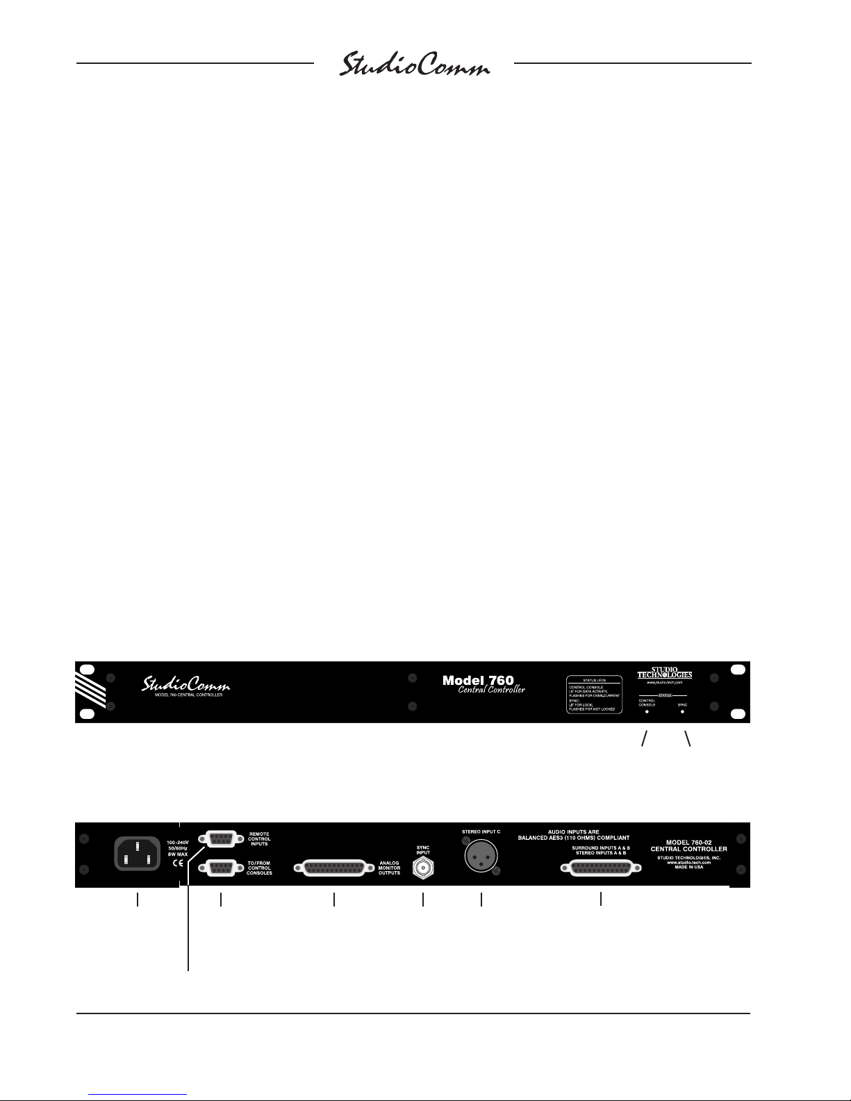
Figure 1. Model 760-02 Central Controller Front Panel
Control console
status LED
Figure 2. Model 760-02 Central Controller Back Panel
AC mains input
Remote control inputs
Issue 3, October 2016 Model 760-02/77 User Guide
Page 6 Studio Technologies, Inc.
To /from
Models 77 &
71 Control
Consoles
Analog
monitor outputs
Sync
input
Stereo
input C
Digital surround (5.1) inputs A & B
and digital stereo inputs A & B
Sync status
LED
Page 7
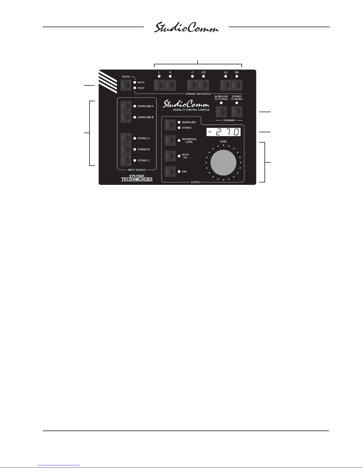
Mute/ solo
mode
for Surround
Channel mute/ solo
Downmix
Input source
select
Figure 3. Model 77 Control Console Front Panel
The Model 760-02 occupies one space (1U)
in a standard 19-inch rack. Digital audio
sources are interfaced with the Model 76002 using one 25-pin female D-subminiature
connector and one 3-pin female XLR connector. A BNC connector is used to interface with an external sync source. Analog
monitor output signal connections are made
using a 25-pin female D-subminiature connector. One 9-pin female D-subminiature
connector is used to connect the Model
760-02 with a maximum of four Model 77 or
Model 71 Control Consoles. A second 9-pin
“D-sub” connector is used to interface with
remote control signals. AC mains power
is connected directly to the Model 760-02,
with an acceptable range of 100 to 240 V,
50/60 Hz.
Additional Details
The Model 77 provides five buttons and associated LEDs for selection of the surround
and stereo input sources to be monitored.
While in most cases only one input source
will be monitored at a time, stereo input C
Monitor output
level display
Surround monitor output
• Surround/ stereo
erence level
• Ref
• Mute all
• Dim
• Rotary level control
can be selected for simultaneous monitoring with one of the two surround or other
two stereo inputs. This allows the two selected inputs to be combined (“summed”).
It’s interesting to note that while each of
the two surround inputs has an LFE channel associated with it, the “.1” channel of
the surround monitor output is designated
as SUB (subwoofer), rather than LFE. This
terminology was carefully selected to highlight the fact that this output channel may
include more than just LFE content. The
bass management function, if enabled,
will redirect low-frequency energy from the
main input channels, combining it with the
LFE content before routing the sum to the
subwoofer output.
The level of the surround and stereo monitor output channels can be controlled by
way of a large, easy-to-use rotary control.
The control, actually a digital encoder,
allows level selection in precise 0.5-dB
steps. The auto mute all function causes
the monitor outputs to automatically mute
whenever the output level control reaches
Model 760-02/77 User Guide Issue 3, October 2016
Studio Technologies, Inc. Page 7
Page 8

for Surround
maximum attenuation. Using the reference
level function, the monitor output levels
can be set to a pre-configured value. This
is provided for audio-with-picture applications that require a specific monitor output
level. The reference level is easily configured by taking an electronic “snapshot” of
the desired monitor output level. For user
confirmation a 4-digit LED readout can display the level of the active monitor output.
To match the needs of a facility, it can be
configured to display either the attenuation
level or the sound pressure level (SPL).
The dim function allows the monitor output
level to be reduced by a fixed dB amount.
The dim level is configured from among
four available values. A mute all function
allows the monitor output to be fully muted.
The channel mute/solo section provides
individual channel monitoring control, allowing a single channel to be muted or
monitored. Multiple channels can also
be simultaneously selected for muting or
“soloing.”
A special solo mode is also provided,
called channel pop solo, which offers a
unique aid when monitoring audio material. Channel pop solo allows the level
of a single monitor output channel to be
raised while the level of the other channels
is reduced. This helps to emphasize the
content on one channel without fully muting the others. Broadcast applications can
benefit from the channel pop solo mode
by allowing, for example, the center channel to be highlighted while still maintaining some level on the other channels. The
amount of level increase—the “pop”—as
well as the amount of attenuation can be
configured to meet the needs of specific
applications or users.
Two functions allow the input sources to be
checked for level or phase inconsistencies.
The surround to stereo downmix function
is used to create a stereo signal from the
selected surround (5.1) source. Key operating parameters in the surround to stereo
downmix function can be configured to
meet the requirements of an application.
This can be especially useful when support for specific international broadcast
standards is required. The stereo to mono
downmix function allows audio on the
left and right input channels to be added
(summed) and monitored on the center
output channel. The two downmix functions
can be simultaneously enabled, allowing
a surround source to be checked for mono
compatibility.
For flexibility, the StudioComm for Surround system is designed to easily integrate with equipment such as production
intercom systems, on-air or recording tally
signals, and audio consoles. Two remotecontrol inputs provide access to the mute
all and dim functions. By providing access
to these functions, talkback or slate activity
from an audio console or other communications system can control the level of the
surround and stereo monitor outputs.
Installation
In this section you will be installing the
Model 760-02 Central Controller in an
equipment rack. Connections to the digital
audio inputs and analog monitor outputs
will be made. A dedicated digital audio
timing reference signal can be connected
to the sync input. If desired, external
equipment will be interfaced to the remote
control inputs. A location will be selected
for the first Model 77 Control Console and
it will be connected to the Model 760-02.
Issue 3, October 2016 Model 760-02/77 User Guide
Page 8 Studio Technologies, Inc.
Page 9

for Surround
AC mains power will be connected to the
Model 760-02. For advanced applications
up to three additional Model 77 or Model
71 Control Console units can be connected to the Model 760-02.
System Components
The main shipping carton contains one
each of the following: Model 760-02 Central Controller, Model 77 Control Console,
9-pin D-sub interconnecting cable, and
user guide. Also included in the shipping carton is a North-American-standard
AC mains cord. Your dealer or distributor
should provide an AC mains cord appropriate for destinations outside of North
America. Any additional Model 77 or Model
71 Control Consoles will be shipped in
separate cartons.
Mounting the Model 760-02
The Model 760-02 Central Controller
requires one space (1U) in a standard
19-inch (48.3 cm) equipment rack. Secure
the Model 760-02 into the equipment rack
using two mounting screws per side. Select a location that is convenient for making
connections to the audio signals as well
as interfacing with the first (or only) Model
77 Control Console. A cable is supplied
to connect the Model 760-02 to the Model
77. If the needs of a specific installation
dictate, an alternate-length interconnecting
cable can be fabricated and used.
Audio Connections
Audio connections are made by way of two
25-pin female D-subminiature connectors
and one 3-pin female XLR connector. All
the connectors are located on the Model
760-02’s back panel. Refer to Figure 2 for
a detailed view of these connectors.
Audio Inputs
Two surround (5.1) and three stereo digital
audio sources can be connected. All sources can be monitored using the surround
(5.1) and stereo monitor output channels.
A one-to-one relationship is maintained
between the input and output channels,
i.e., left input to left monitor output, right input to right monitor output, center input to
center monitor output, etc. (Of course this
won’t be true in the case where the user
has enabled one or both of the downmix
functions.)
The audio inputs support digital audio signals with a sampling rate of up to 192 kHz
and a word length (depth) of up to 24 bits.
It’s best if the connected signal sources
maintain a common sample rate and timing reference. Having all signals “locked”
together helps to ensure proper handling
by the Model 760-02’s all-digital signal
control path.
There is, however, an exception worth noting. Circuitry associated with stereo input
C has sample rate conversion (SRC) capability, allowing virtually any digital audio
signal to be connected. A signal connected
to stereo input C can have an independent
sample rate and timing reference and still
be monitored correctly. Refer to the Technical Notes section of this user guide for a
detailed review of the SRC capability.
The Model 760-02’s digital audio inputs
are intended for connection with balanced
digital audio sources that are compatible
with the AES3 standard. This signal type
has a nominal impedance of 110 ohms
and a nominal signal level of 5 Vpp.
One 25-pin female D-subminiature connector (DB-25F) is used to interface with
the 16 channels associated with surround
Model 760-02/77 User Guide Issue 3, October 2016
Studio Technologies, Inc. Page 9
Page 10

for Surround
input A, surround input B, stereo input A,
and stereo input B. Each of the eight physical connections supports two audio channels. Often a wiring assembly prepared for
these digital audio inputs would typically be
identical to that of a TASCAM-type (AES59compliant) input assembly. An assembly of
this type would have eight 3-pin female XLR
connectors on one end and a 25-pin male
D-subminiature connector (DB-25M) on the
other. Refer to Figure 4 for details on connecting with the 25-pin female D-subminiature connector.
On the Model 760-02 stereo input C uses a
3-pin female XLR connector for interfacing
with a digital audio signal source. The mating cable should have a 3-pin XLR connector wired such that signal + goes to pin 2,
the – signal to pin 3, and shield to pin 1.
Unbalanced AES3 digital audio signals can
also be used with the Model 760-02’s inputs
if external coupling transformers (“baluns”)
Signal Signal
Connections Channel High (+) Low (–) Shield
Surround Input A L/R 1 24 12 25
Surround Input A C/LFE 2 10 23 11
Surround Input A LS/RS 3 21 9 22
Stereo Input A 4 7 20 8
Surround Input B L/R 5 18 6 19
Surround Input B C/LFE 6 4 17 5
Surround Input B LS/RS 7 15 3 16
Stereo Input B 8 1 14 2
are utilized. These impedance-matching (75
ohms to 110 ohms) and level step-up transformer assemblies typically provide a BNC
connector on their input and a 3-pin male
XLR connector on their output.
Analog Monitor Outputs
The connector labeled Analog Monitor
Outputs provides access to the Model
760-02’s 6-channel (5.1) surround and
2-channel stereo analog monitor outputs.
The surround analog monitor output channels are intended to connect to analog
inputs associated with the surround loudspeaker system incorporated in a facility.
The stereo analog monitor output allows
support for a secondary set of stereo
monitor loudspeakers.
The analog monitor output channels are
designed for connection to audio amplifiers
associated with monitor loudspeakers or
to the inputs of loudspeakers that contain
integrated amplifiers. The analog monitor
outputs are electronically balanced and
will perform optimally when driving loads
of 2000 (2 k) ohms or greater. In most applications 3-pin male XLR connectors will
be used to interface with the inputs on the
associated amplifiers or amplified speakers.
In this case the + terminal would go to pin 2
of the XLR, the – terminal to XLR pin 3, and
the shield terminal to XLR pin 1.
Notes: 1) All signals transformer-coupled digital audio;
balanced AES3 (110 ohms,
2) Connector type on Model 760-02 is 25-pin female
D-subminiature (DB-25F). Installer must provide male
(DB-25M). Connector uses 4-40 threaded inserts for
locking with mating plug.
3) Wiring scheme follows AES59-2012 convention.
Standard TASCAM-type wiring harnesses are directly
compatible, with the possible exception of 4-40 screw
threads being required.
Figure 4. Connections for Surround A,
Surround B, Stereo A, and Stereo B Digital Inputs
Issue 3, October 2016 Model 760-02/77 User Guide
Page 10 Studio Technologies, Inc.
5 Vpp) compatible.
Balanced operation of the analog monitor
outputs is the preferred connection method
but unbalanced operation does not pose a
problem. To connect to an unbalanced load
connect the + terminal as signal high, and
only the Model 760-02’s shield terminal as
the signal low/shield. Leave the – terminal
unconnected. For correct unbalanced operation, it is important not to connect – and
shield together.
Page 11

for Surround
The wiring scheme used by the D-subminiature connector complies with AES592012, as made popular by TASCAM. A
wiring assembly prepared for the Model
760-02’s analog monitor outputs is identical to that of a TASCAM-type output assembly. Please refer to Figure 5 for the
exact connection details. Again note that
unlike a TASCAM-type assembly, the
Model 760-02’s D-sub connectors use
4-40 threads.
Signal Signal
Connections Channel High (+) Low (–) Shield
Surround L 1 24 12 25
Surround R 2
Surround C 3
Surround SUB 4 7 20 8
Surround LS 5
Surround RS 6 4 17 5
Stereo L 7
Stereo R 8 1 14 2
Notes: 1) Connector type on Model 760-02 is 25-pin female
D-subminiature (DB-25F). Installer must provide male
(DB-25M). Connector uses 4-40 threaded inserts for
locking with mating plug.
2) Wiring scheme follows AES59-2012 convention.
Standard TASCAM-type wiring harnesses are directly
compatible, with the possible exception of 4-40 screw
threads being required.
Figure 5. Connections for Analog Monitor
Outputs
10 23 11
21 9 22
18 6 19
15 3 16
Sync Input
The Model 760-02 requires a timing reference (sync) signal so that the digital audio
input signals will be handled correctly. A
configuration setting allows the source of
sync to be the L/R input of the currently selected surround or stereo digital audio input. While this is acceptable, audio artifacts
(clicks or noise) can occur when switching
between inputs. A better method is to connect a dedicated timing reference signal to
the Model 760-02’s sync input connector.
The connected sync signal must maintain
a stable relationship between itself and the
digital audio input signals. The actual sync
source can be in one of several formats:
word clock, DARS (AES11), bi-level video,
or tri-level video.
An overview of the various compatible
timing reference signals might prove
worthwhile. Word clock is a digital signal
that is locked in phase and frequency to
the sample rate of the associated digital
audio sources. DARS (digital audio reference source) is a timing signal compliant
with the AES11 standard. It’s sometimes
referred to as “AES3-black.” Technically it is
similar to an AES3 signal but is generated
specifically as a timing reference signal.
Bi-level video sync signals were originally
provided to support NTSC and PAL broadcast applications, although they continue
to be used by contemporary equipment.
Tri-level sync signals were primarily associated with facilities that supported highdefinition (HD) video equipment however
the importance of this type of sync seems
to be waning. Both bi-level and tri-level
signals can be found at numerous rate
combinations, configured to allow for compatibility with the various video formats.
With the wide range of allowable sync
sources proper Model 760-02 operation
should be easy to obtain. Extensive testing
has been done using many different sync
source types and rates. Interested users
can refer to Appendix B of this user guide
for details.
An external sync reference source should
be connected to the sync input BNC connector located on the Model 760-02’s back
panel. For flexibility this input can be configured to be high-impedance (“floating”) or
Model 760-02/77 User Guide Issue 3, October 2016
Studio Technologies, Inc. Page 11
Page 12

for Surround
terminated with an impedance of 75 ohms.
A sync source that is dedicated for use by
the Model 760-02’s sync input will typically
have input termination enabled. If the sync
signal connected to the Model 760-02 is
being connected (“multed”) to other inputs
it may be desirable for the termination to be
disabled. A general “rule of thumb” is that
termination should be applied only at the
location of the last physical device using a
sync signal.
Remote Control Inputs
Support is provided for two remote control
input functions: remote mute all and remote
dim. These functions impact the surround
and stereo monitor outputs. The Model
760-02’s inputs use logic gates, “pulled up”
to 3.3 Vdc by way of resistors, which are
active whenever they are brought to their
logic low state. Inputs of this type are commonly referred to as GPI inputs. While the
input circuitry is protected from over-current
and static discharge (ESD), care should be
taken to prevent nasty signals from reaching them. The inputs are active only when
held in the low state; they can’t be configured to change state (“latch”) in response
to a logic pulse.
Signal Pin Direction
Data Shield 1 Shield
Remote Mute All 5 Input
Remote Dim 6 Input
Remote Spare 1 8 Input
Remote Spare 2 9 Input
Remote Common 4 Common
Note: Connector type on Model 760-02 is 9-pin f
D-subminiature (DE-9F). Connector uses 4-40
threaded inserts for locking with mating plug.
Figure 6. Connections for Remote Control
Inputs
emale
Connecting the Model 760-02
to the Model 77
A 9-pin female D-subminiature connector, labeled To/From Control Consoles, is
provided on the back panel of the Model
760-02 Central Controller. This is used to
interface the unit with Model 77 Control
Consoles. Refer to Figure 7 or Appendix A
for details. A 9-pin female D-sub connector, labeled To/From Central Controller, is
provided on the back panel of each Model
77 Control Console. A cable with 9-pin
male D-sub (DE-9M) connectors on each
end is used to interconnect the Model
760-02 with the Model 77 units. A cable is
A 9-pin D-subminiature connector is used
for the remote control inputs. Refer to
Figure 6 or Appendix A for the exact connection details. Note that pin 4 (remote
common) connects to the Model 760-02’s
internal circuit common connection as well
as to the Model 760-02’s chassis and mains
earth connections. Figure 6 also shows two
spare remote control inputs (pins 8 and 9).
These are provided for future applications
and should remain unconnected.
Issue 3, October 2016 Model 760-02/77 User Guide
Page 12 Studio Technologies, Inc.
Signal Pin Direction
Data + (RS-485) 1 To/From Models 77/71
Data – (RS-485) 6 To/From Models 77/71
Data Shield 2 To/From Models 77/71
DC + (12 V) 4 To Models 77/71
DC – (12 V Return) 9 To Models 77/71
DC Power Shield 5 To/From Models 77/71
Note: Connector type on Model 760-02 is 9-pin female
D-subminiature (DE-9F). Connector uses 4-40
threaded inserts for locking with mating plug.
Figure 7. Connections between Model 760-02
and Model 77 and Model 71
Page 13

for Surround
included in the shipping carton. The cable
implements all nine connector pins in a oneto-one manner.
Should an interconnecting cable of a different length be required there’s no problem
for one to be fabricated and used. While it
can be wired in a one-to-one fashion supporting all nine pins, only four connections
are required: pin 1 (data +), pin 6 (data –),
pin 4 (DC +), and pin 9 (DC –). The Model
760-02’s connector pin-out scheme was designed to allow creation of an interconnecting cable which uses commonly available
2-pair audio cable. This cable, consisting
of two twisted pairs each with an individual
shield, is typically sleek, flexible, and available in many colors. One pair and shield can
be used for the data connections while the
other pair and shield can be used for the DC
connections. This implementation has the
advantages of providing a shield for the data
path and a more robust common connection
(two conductors including the shield) for the
DC power circuit.
A few simple calculations are required to
determine the maximum cable length when
connecting a Model 760-02 to a Model 77.
The differential transmission scheme used
by the system’s RS-485 interface makes an
interconnection in excess of 1000 feet (>300
meters) easily possible. The limiting factor
is typically the ability of the wiring to pass
the DC power supplied by the Model 760-02
to a Model 77. The Model 760-02 supplies
12 Vdc with a maximum current of 500
milliamperes (mA).
The Model 77 requires a minimum of 9 Vdc,
100 mA, for correct operation. (The voltage
must be measured directly at the Model 77’s
9-pin connector.) So the maximum interconnecting cable length is directly related to the
resistive voltage losses associated with the
two DC-carrying conductors. As the Model
760-02 supplies 12 V and the Model 77
requires 9 V minimum, this directly leads to
a 3 Vdc maximum drop due to the interconnecting cable. Using Ohm’s law it’s quite
easy to determine whether the selected
cable will support the desired interconnection length. Calculate the voltage drop by
multiplying the total resistance (in ohms) of
the proposed cable by 0.1 (the Model 77’s
required current in amperes). Remember to
include the resistance in both the DC + and
DC – wires when calculating the voltage
drop. If it’s greater than 3 V your cable is too
long or the wire gauge is too small.
Additional Control Consoles
Some installations may benefit from the
Model 760-02’s ability to be controlled by
additional control consoles. At least one
Model 77 Control Console must be connected to the Model 760-02 Central Controller. After this requirement has been met
up to three additional Model 77 or Model 71
Control Consoles can also be connected to
and powered by the Model 760-02.
When connecting multiple control consoles
to a Model 760-02 all nine pins of each
interconnecting cable can be connected in
parallel (“multed”). Using this arrangement
the data and 12 Vdc power signals between
all the units will be multed. A custom cable
implementation requires just four pins to be
connected: pin 1 (data +), pin 6 (data –), pin
4 (DC +), and pin 9 (DC –).
To make installation simple, a “bus” cable
assembly can be created using a short
length of ribbon cable with one male and
multiple 9-pin female D-subminiature insulation-displacement connectors attached.
Then standard 9-pin cables can link the
control consoles with the connectors on the
bus cable.
Model 760-02/77 User Guide Issue 3, October 2016
Studio Technologies, Inc. Page 13
Page 14
for Surround
Refer to the previous paragraphs of this
user guide where the issues involving
Model 760-02 to Model 77 cable length
are discussed. Note the required current
for a Model 77 is 100 mA while a Model
71 requires only 35 mA. It’s important to
review this information prior to creating
the interconnection scheme to be used for
installing multiple Model 77 units.
AC Mains Power
The Model 760-02 operates directly from
AC mains power of 100 to 240 V, 50/60 Hz.
Being a “universal input” device, there are
no switches to set or jumpers to install to
match a location’s mains voltage. The unit
uses a 3-pin IEC 320 C14-type inlet connector to mate with a detachable mains
cord. All units are supplied with a mains
cord that has a North-American-standard
plug (NEMA 5-15L) on one end and an
IEC 320 C13 socket on the other. Units
bound for other destinations require that
the appropriate cord be used. The wire colors in the mains cord must conform to the
internationally recognized color code and
should be terminated accordingly:
Connection Wire Color
Neutral (N) Light Blue
Line (L) Brown
Protective Earth (E) Green/Yellow
Safety Warning: The Model 760-02
does not contain an AC mains disconnect switch; the AC mains cord
plug serves as the disconnection
device. Safety considerations require
that the plug and associated outlet
be easily accessible to allow rapid
disconnection of AC mains power
should it prove necessary.
As soon as mains power is applied the
Model 760-02 will perform a power-up
sequence. The two LEDs on the right side
of the front panel will individually light in a
rapid right-to-left test sequence. Then the
LEDs will flash in cadence while the firmware loads into the Model 760-02’s main
logic device. After just a few seconds initial
system operation will commence and the
two LEDs will perform their intended functions. Once operating data is being interchanged with the one or more connected
Model 77 or Model 71 Control Consoles
the control console status LED will also
light. The sync status LED will light if a
valid sync source has been recognized.
The sync status LED will flash if a valid
sync source is not recognized.
Also upon application of mains power, all
connected Model 77 units will go through
a power-up sequence, lighting each of its
LEDs in succession. Using its 4-digit display, each Model 77 will then momentarily
display its address, its software version,
and the main and logic device software
versions of the associated Model 760-02.
All connected Model 71 units will also go
through a power-up sequence after mains
power is applied to the Model 760-02.
Each of the Model 71’s three LEDs will
light momentarily. After these LEDs have
been lit, the device address will be shown
briefly using the dim and reference level
LEDs, as shown in Figure 8 in the Configuration section. When this is complete the
Model 71 will begin normal operation and
its status LED will light if communication is
established with the Model 760-02. If the
Model 71’s status LED does not light check
to see if there is a device address conflict
among all connected control consoles and
that all cables are connected properly.
Issue 3, October 2016 Model 760-02/77 User Guide
Page 14 Studio Technologies, Inc.
Page 15

for Surround
Should an error be detected during the
start-up process the two LEDs on the
Model 760-02’s front panel will remain
flashing in cadence. On the Model 77 units
a diagnostic code may be displayed. Refer
to the Technical Notes section of this user
guide for details.
Only after the Model 760-02 and all connected Model 77 and Model 71 units have
correctly powered up will full system operation begin.
Configuration
After the physical installation has been
completed it’s important that the system’s
configuration options be carefully reviewed.
In most cases one or more of the operating
parameters will need to be revised to meet
the needs of the specific installation. Many
of the configuration parameters will impact
the signal flow in to and out of the Model
760-02 Central Controller. Other parameters affect how the one or more Model
77 Control Consoles will display status
conditions and respond to user commands.
Most of the configuration choices will be
made using a Model 77 Control Console.
However, two configuration choices are
available for each of the connected Model
71 Control Consoles.
Configurable Parameters
Many StudioComm functions can be configured to meet the exact needs of an
installation. A Model 77 Control Console
is used to display and select the desired
system configuration. Here’s an overview
of what can be configured:
• Model 77 Device Address (must be
unique for each unit!)
• Stereo Input C Sample Rate Converter
• Stereo Monitor Output
• Bass Management
• Mute/Solo Bass Management Mode
• Sync Source
• Sync Input Termination
• Audio-Synced-to-Video Sample Rate
• Reference Level
• Overall Display Mode
• Reference Level in dB SPL
• Auto Reference Level Off
• Dim Level
• Remote Inputs
• Surround to Stereo Downmix Levels
• Channel Pop Solo Mode Offset Levels
• Input Delay A and B
• Monitor Output Channel Level Offsets
The configuration diagrams, located later
in this section, give details on setting each
parameter. An overview of each configurable parameter is provided in the following
paragraphs.
Entering and Exiting the
Configuration Mode
A small button is located on the back of
each Model 77 Control Console, adjacent
to its 9-pin female D-sub connector. On
any connected Model 77 pressing and
holding this button for two seconds places
both this specific unit and the Model 76002 into their configuration modes. Other
connected Model 77 and Model 71 units
will enter a standby mode. When the Model
760-02 enters its configuration mode it will
immediately mute the monitor outputs as
a speaker protection measure. When a
Model 77 enters the configuration mode its
Model 760-02/77 User Guide Issue 3, October 2016
Studio Technologies, Inc. Page 15
Page 16

for Surround
array of buttons and LEDs no longer perform their normal functions, instead they
are used to display the operating parameters and reflect configuration changes as
they are made.
As a user aid, a Model 77 that has entered
the configuration mode will have its mute
and solo LEDs (associated with the channel mute/solo section) light in an alternating manner. Other connected Model 77
units will indicate that they have entered
the standby mode by simultaneously flashing their mute and solo LEDs.
To leave the configuration mode and return
the system to normal operation requires
one last action to be made on the Model
77 unit that’s in its configuration mode;
press and hold its configuration button
for two seconds. Note that configuration
changes are stored in nonvolatile memory
only after the configuration mode has been
exited.
Our apologies to those of you who find the
configuration button a pain to use, but it’s
supposed to be that way! Seriously, the top
of the button is slightly recessed from the
back panel, making it harder to accidentally activate. We didn’t want normal operation to cease because someone pushed a
Model 77 into a “rats nest” of schedules,
memos from management, and empty coffee cups! But a firm press with the fleshy
part of an index finger should do the trick.
There is no problem frequently “tweaking” the system’s operating parameters
to achieve the desired performance. The
configuration data is stored in nonvolatile
memory, which is rated for thousands of
read and write cycles and a retention time
in tens of years. Note that memory integrated circuits are located in the Model
760-02 Central Controller as well as the
Model 77 and Model 71 Control Consoles.
The individual device address is stored in
each Model 77. The device address and
button configuration parameters are stored
in the Model 71. All other configuration parameters are stored in the Model 760-02.
Model 77 Device Address
A unique device address must be assigned
to each Model 77 that is connected to a
Model 760-02. The choices are A1, A2, A3,
or A4, with the default address being A1. As
most installations will find only one Model
77 utilized, its default setting is appropriate. For installations that use a second,
third, or fourth Model 77 each unit must be
configured with a unique device address.
Problems will occur if more than one unit
has the same address! It’s important to
highlight the fact that the device address is
the only setting that must be done on each
individual Model 77 unit. All other settings
can be made on any one of the connected
Model 77 units. Be sure that any selected
address does not conflict with addresses to
be assigned to Model 71 units.
Stereo Input C Sample Rate
Converter
Circuitry associated with stereo input C can
provide sample rate conversion (SRC) for
digital audio signals connected to that input.
The acceptable input range for sample rate
conversion is very wide, but is dependent
upon the output sample rate. With an output sample rate of 48 kHz any signal with
a sample rate over a range of 8 to 216 kHz
can be properly monitored by the system.
This capability can be especially useful
with signals that are not synchronized
with respect to the others connected to the
Model 760-02, even if the sample rate is
identical. The only compromise is that the
Issue 3, October 2016 Model 760-02/77 User Guide
Page 16 Studio Technologies, Inc.
Page 17

for Surround
SRC process adds a fixed input-to-output
(group) delay of approximately 1 millisecond, a value that shouldn’t impact most installations. As such, it’s recommended that
the sample rate converter remain enabled.
However there might be special cases
where this resource isn’t desired and it can
be disabled.
Stereo Monitor Output
In addition to the surround monitor output, a separate stereo monitor output is
also provided. By default the stereo output
can be enabled by a user. In applications
where stereo monitor loudspeakers are not
connected to the stereo monitor output, the
output can be disabled. This can minimize
confusion, preventing a user from attempting to select the stereo monitor output.
Bass Management
The Model 760-02 incorporates flexible
and sonically excellent bass management capabilities. It is, however, limited to
functioning only at sample rates of 44.1,
48, 88.2, and 96 kHz. Five configuration
parameters are used to enable or disable
bass management as well as to select
the characteristics of the associated audio filters. While the settings are simple
to make, great care must be taken in first
reviewing the entire monitor system. Only
after a full understanding of the performance of the associated surround and,
if present, stereo loudspeaker systems are
determined can a plan for bass management be established.
Bass management can be enabled so that
the function is active when the surround
monitor output is enabled. It can also be
independently enabled so that it can be
active when the stereo monitor output is
enabled. By default bass management for
both the surround and stereo outputs is
disabled. The crossover point of the bass
management filters can be selected from
among four choices: 40, 50, 60, or 80 Hz.
The slope of the low-pass and high-pass
filters associated with bass management
can be independently selected. The choices are 12 dB-per-octave or 24 dB-peroctave with the latter being the default.
Mute/Solo Bass Management
Mode
The Model 760-02’s mute/solo function
can be configured for how it performs in
applications where bass management has
been enabled. This is a somewhat-esoteric
topic but can be important in certain situations. The default setting for the mute/solo
bass management mode is for pre-bass
management. This means that if one channel has been selected for, as an example,
soloing then the bass management filters
will send any associated low-frequency
content to the subwoofer output. So in this
case the solo function is really an “input
channel” solo since the actual acoustical
energy associated with that one channel
will be reproduced by both the main channel and the subwoofer loudspeakers.
The mute/solos bass management mode
can also be set for post-bass management. When this mode is enabled a channel selected for soloing will cause only its
associated monitor output channel to remain active. So if, for example, one of the
main surround input channels (one of the
“5.” channels) is selected for soloing then
all monitor output channels except that one
will mute. The bass management filters
will remain enabled, thus sending only the
high-passed audio energy from the soloed
Model 760-02/77 User Guide Issue 3, October 2016
Studio Technologies, Inc. Page 17
Page 18

for Surround
input channel to the soloed output channel.
Only if the LFE channel has been selected
for soloing will the subwoofer output remain
active. Typically the only reason why the
post-bass management mode would be
selected is when troubleshooting issues
with the loudspeaker system.
Sync Source
The Model 760-02 requires that the designated external timing reference (sync) be
defined. Three of the choices—word clock,
DARS, and video—are associated with a
signal that is connected to the sync input
BNC connector. The fourth choice allows the
L/R input of the currently selected surround
or stereo digital audio input to serve as the
system’s sync source.
Sync Input Termination
The sync input circuitry can be configured
to terminate the signal connected to the
back-panel sync input BNC connector. When
termination is selected a 75 ohm load is
applied to the signal. When the sync input
is not terminated the input impedance is
very high, essentially applying no load to the
source. If the sync source is connected only
to the Model 760-02 then enabling termination is typically appropriate. However, if the
sync source is being “shared” by multiple
inputs then care must be taken so that the
signal is only terminated by one device.
Reference Level
For audio-with-picture applications it’s
often beneficial for monitoring to be done
in reference to a known loudspeaker level.
This is often referred to as “mixing to 85
dB” on the monitors. The StudioComm for
Surround system allows a precise monitor
output level to be stored and then enabled
by pressing the Model 77 button labeled
Reference Level. Setting the reference
level is very simple but care is required.
Typically this will be done in reference to
the surround monitor output, rather than
the stereo monitor output:
1. Set up a precision sound pressure
level (SPL) measuring device at the
desired listening location.
2. Place the StudioComm system in the
normal operating mode, not the configuration mode. Be certain that the dim,
mute all, reference level, and downmix
functions are not active. The remote
mute all and remote dim functions
must also not be active.
3. Use the Model 77 Control Console to
select the input source that contains
the desired reference signal source,
e.g., pink noise.
4. Observing the SPL meter, adjust the
Model 77’s rotary level control until the
desired loudspeaker system reference
level has been reached.
Audio-Synced-to-Video
Sample Rate
If a video sync signal is being used as the
Model 760-02’s timing reference the sample
rate of the connected digital audio signals
must be specified. In most cases the default
value of 48 kHz will be appropriate, but rates
from 32 to 192 kHz are available.
Issue 3, October 2016 Model 760-02/77 User Guide
Page 18 Studio Technologies, Inc.
5. Being careful not to disturb the position of the rotary level control, enter the
configuration mode by pressing and
holding the configuration button located on the Model 77’s back panel.
Page 19

for Surround
6. Once the configuration mode has been
entered, all the monitor outputs will
mute. Press and hold the reference
level button; its associated LED will
begin to flash. After five seconds the
LED will light steadily to indicate that a
“snapshot” of the new reference level
has been taken. The Model 77’s numeric display will then show the value
of the new reference level. The value
shown will always be a negative number as it’s always a value less than the
maximum output level. The reference
level button can now be released.
7. To complete the process the configuration mode must be exited. This
is performed by again pressing and
holding the configuration button for
two seconds. The new reference level
is now stored in the Model 760-02’s
nonvolatile memory. Only by repeating
the entire procedure can the value be
changed.
Once the configuration mode has been exited, the monitor outputs will again become
active. Confirm that the correct level has
been stored by pressing the reference level
button. The SPL meter should display the
desired level. If not, repeat the calibration
procedure to achieve the desired goal.
You might wonder why you have to press
and hold the reference level button for
five seconds before the selected value is
recognized. This is provided specifically so
that unauthorized users won’t accidentally
change the reference level while they experiment with the configuration mode. Only
if you know the “secret” will you be able to
store a new value.
Overall Display Mode
The Model 77’s 4-digit numeric display can
be configured to display the monitor output level in either an attenuation mode or
an SPL mode. In the attenuation mode the
output level is shown as a reduction in level,
in dB, relative to the maximum output level.
When the rotary control is used to set the
output level to its maximum the display will
show 0.0. As the rotary control is turned in
the counterclockwise direction the display
will show negative values, reaching –70.0
before the full mute function automatically
mutes the monitor outputs.
In the SPL mode the display can be configured to allow the output level to be
presented to users in terms of the actual
sound pressure level (SPL). It is used in
conjunction with the reference level in dB
SPL configuration and the stored reference
level. The SPL mode allows a user to see a
visual representation of the SPL level that is
present in the listening environment. While
it takes a little more care to correctly implement the SPL display mode, it can offer
an enhanced experience for StudioComm
users.
Reference Level in dB SPL
The reference level in dB SPL configuration
allows a specific SPL value to be associated with the stored reference level value. In
this way whenever the monitor output is at
the reference level, either through activating the reference level function or manually adjusting the rotary level control, the
Model 77’s display will show the configured
SPL level. Whenever the monitor output is
not at the reference value the display will
show the current value, in dB, relative to
the reference level. The reference level in
dB SPL can be configured over a range of
Model 760-02/77 User Guide Issue 3, October 2016
Studio Technologies, Inc. Page 19
Page 20

for Surround
70.0 to 100.0 dB in 1.0-dB steps. In many
applications selecting a value of 85 would
be appropriate, reflecting the widely used
audio-for-picture 85 dB monitoring reference level. (Typically this 85 dB is really
85 dBC, indicating that a C-weighting filter
has been applied to the measurement.)
Other common reference SPL values, such
as 82 dB and 87 dB, are well within the allowable range.
Auto Reference Level Off
When auto reference level off is enabled,
the function automatically turns the reference level function off if a change is made
to the rotary level control while the reference level function is active.
Dim Level
The dim function is used to reduce the
monitor output level by a preset amount.
The reduction is in dB relative to the monitor output’s current level. There are four
dim level values available: –10.0, –15.0,
–20.0, and –25.0 dB.
Remote Mute All
Two configuration choices are associated
with the remote mute all function: disabled
and enabled. To utilize the remote mute all
function simply requires you to select the
enabled setting.
Remote Dim
that may be present on associated video
signals. The time delay applies to all input
signals and cannot be applied selectively.
A configured delay time is referenced to
a sample rate of 48 kHz. In the case of
input signals with a sample rate of 48 kHz
the delay range is 0 to 340 milliseconds
in 1-millisecond steps. For other sample
rates the time must be linearly scaled. For
example, for a sample rate of 96 kHz the
actual time range is 0 to 170 milliseconds.
In this case selecting a delay of 120 on the
Model 77 will result in an actual time delay
of 60 milliseconds.
For operating flexibility two different input
delay values can be selected and stored
during the configuration process. These
can then be enabled as required by the
user during normal system operation. The
default value for both Delay A and Delay
B is 0 milliseconds. Typical applications
would require only one input delay to be
configured. But in other cases two different, both non-zero, input delay values will
be selected. This could be appropriate in
applications where multiple video display
systems are being used in the same control room or monitoring facility. Each video
display may exhibit its own processing
latency and audio would need to be “lined
up” accordingly. During normal StudioComm operation a user can select the appropriate input delay for the display system
currently being utilized.
Two configuration choices are associated
with the remote dim function: disabled and
enabled. To utilize the remote dim function
simply configure it for enabled.
Input Delay
A time delay can be added to the input
signals, allowing compensation for delays
Issue 3, October 2016 Model 760-02/77 User Guide
Page 20 Studio Technologies, Inc.
Surround to Stereo Downmix
Levels
The surround to stereo downmix function
is a useful tool for checking the compatibility of surround (5.1) input signals with
stereo and monaural playback environments. The exact technical formula for how
Page 21

for Surround
the Model 760-02 handles the surround to
stereo downmix function can be selected
by way of four configurable parameters.
The default settings create a good generalpurpose function that’s effectively used by
numerous users of Studio Technologies’
StudioComm for Surround products. But
there are application-specific situations
where modifying one or more of the parameters will be appropriate. This can be in
response to a personal choice in monitoring methods or, more frequently, to meet
the requirements of international broadcast
standards.
When the surround to stereo downmix
function is active the path from the left (L)
input channel to the left monitor output
channel and the right (R) input channel to
the right monitor output channel is maintained. A configuration choice allows the
level of the L and R inputs routed to the L
and R outputs to be selected. By default,
when the surround to stereo downmix
function is active the level of the L and R
inputs remain at unity, with no gain or loss
applied. An alternate setting allows the
level of L and R input channels to be reduced (attenuated) by 3 dB. (The available
changes in signal level can also be notated
as 0 dB or –3 dB.)
When the surround to stereo downmix
function is active the left surround (LS)
input is routed to the left (L) monitor output; the right surround (RS) input is routed
to the right (R) monitor output. By default
the level of the LS and RS signals routed
to L and R will be reduced (attenuated) by
3 dB. An alternate setting allows the levels
to be reduced by 6 dB. (These settings can
also be notated as –3 dB and –6 dB.)
When the surround to stereo downmix
function is active the center (C) input is
routed to both the left (L) and right (R)
monitor outputs. By default the level of the
C signal routed to L and R will be reduced
(attenuated) by 6 dB. An alternate setting
allows the attenuation level to be 3 dB.
(These levels can also be notated as –3 dB
and –6 dB.)
By default, when the surround to stereo
downmix function is active the LFE channel
associated with a surround input is fully attenuated (muted). This removes LFE content from the “downmixed” signal. In most
applications this is appropriate. However,
for special situations a configuration mode
allows the LFE channel to be reduced by 6
dB and routed to both the left (L) and right
(R) monitor outputs.
A last word on configuring the surround to
stereo downmix function: no matter what
choices are made when the function is active the center (C), left surround (LS), right
surround (RS), and subwoofer (SUB) monitor outputs will fully mute.
Channel Pop Solo Mode Offset
Levels
Two parameters can be configured that
determine how the channel pop solo function impacts audio levels. The up offset level
sets the amount of increase (gain) that a
channel will experience when it is soloed
in the channel pop solo mode. The down
offset level sets the amount of decrease (attenuation) that the non-soloed channels will
experience when a channel is active in the
channel pop solo mode. Refer to Figure 10
for details.
Monitor Output Level Offsets
To provide assistance during room calibration, the relative output levels of the surround and stereo monitor output channels
Model 760-02/77 User Guide Issue 3, October 2016
Studio Technologies, Inc. Page 21
Page 22

for Surround
can be adjusted over a limited range. The
eight channels can be adjusted in 0.5-dB
steps over a ±12-dB range. During configuration the displayed value represents the dB
level difference as compared to the nominal
output level. In most cases one surround
and one stereo channel should serve as the
overall reference level and not be changed.
This is typically the center channel for surround and the left channel for stereo.
This feature is provided primarily for use
when the monitor output channels are connected to loudspeaker systems that don’t
offer a means of “trimming” the input sensitivity of individual channels. Without this
capability, minor adjustments to the output
level of specific loudspeakers to account for
room acoustics wouldn’t be possible.
It’s also possible to use the StudioComm’s
output level offset capability to adjust the
overall monitor output levels to allow matching to the input sensitivity of loudspeaker
systems. In this case all the channels (six
for surround, two for stereo) would be configured to have the same output level offset
setting. For example, the six surround channels could all be configured to have a –3.5
dB output level offset. However, great care
must be taken when configuring a system
in this manner. The dynamic range or noise
floor of the audio signals will be impacted
and extreme settings could lead to poor
monitor system performance.
Restore Factory Defaults
The restore factory defaults function is
provided primarily for factory use. In this
way a system can be shipped with the
default settings selected. While you are
welcome to use this function, be careful so
that your configuration efforts aren’t wasted.
Specifically, be aware that the reference
level is reset to minimum level. All the other
parameters are fairly easy to set up, but
resetting the reference level would require
getting out an SPL meter and a calibrated
signal source. This is a hassle you may not
need!
Model 71 Control Console
Configuration
Two configuration choices are available on
each Model 71. One is its device address;
the other is the button disable mode. A
small button is located on the back of each
Model 71 Control Console, adjacent to the
9-pin female D-sub connector. Pressing
and holding this button for two seconds
places this specific unit in its configuration mode; normal operation of the Model
760-02 and other connected Model 71
and Model 77 units will continue. When a
Model 71 enters its configuration mode
its three LEDs will no longer perform their
usual functions. Instead the status LED will
blink to indicate that configuration mode is
active. Refer to Figure 8 for details.
Device Address
The dim and reference level LEDs will
display the Model 71’s current device
address. The rotary level control is used
to select the desired device address; the
LEDs will respond accordingly. The device
address must be selected so as not to conflict with the device address of any other
connected Model 71 or Model 77 Control
Console. The choices are A1, A2, A3,
and A4. All Model 71 units have a default
device address of A4; Model 77’s units
have a default device address of A1. This
ensures that, in most cases, no change
will have to be made. Refer to Figure 9 for
details.
Issue 3, October 2016 Model 760-02/77 User Guide
Page 22 Studio Technologies, Inc.
Page 23
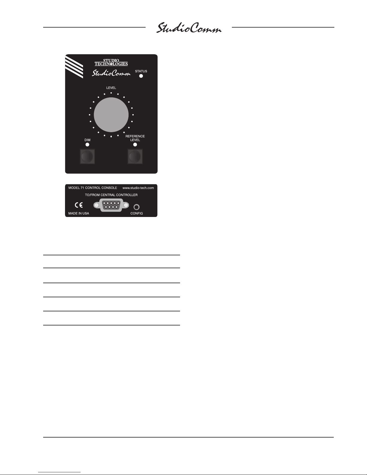
Figure 8. Model 71 Control Console Front and
Back Panels
for Surround
Button Disable
To disable the Model 71’s buttons, simultaneously press and hold both the dim and
reference buttons for two seconds. When
the disable request has been recognized
the LEDs above both buttons will flash
rapidly. Release the buttons and they will
no longer enable or disable their normal
functions. To return the buttons to normal
operation simultaneously press and hold
both buttons for two seconds at which time
the two LEDs will flash rapidly.
To leave the configuration mode and return
a Model 71 to normal operation requires
one last action: again press and hold its
configuration button for two seconds. The
selected configuration parameters will be
stored in a nonvolatile memory device that
is located inside this specific Model 71.
Address Dim LED Reference Level LED
A1 OFF OFF
A2 OFF ON
A3 ON OFF
A4 ON ON
Figure 9. Model 71 Device Address Chart
Model 760-02/77 User Guide Issue 3, October 2016
Studio Technologies, Inc. Page 23
Page 24
for Surround
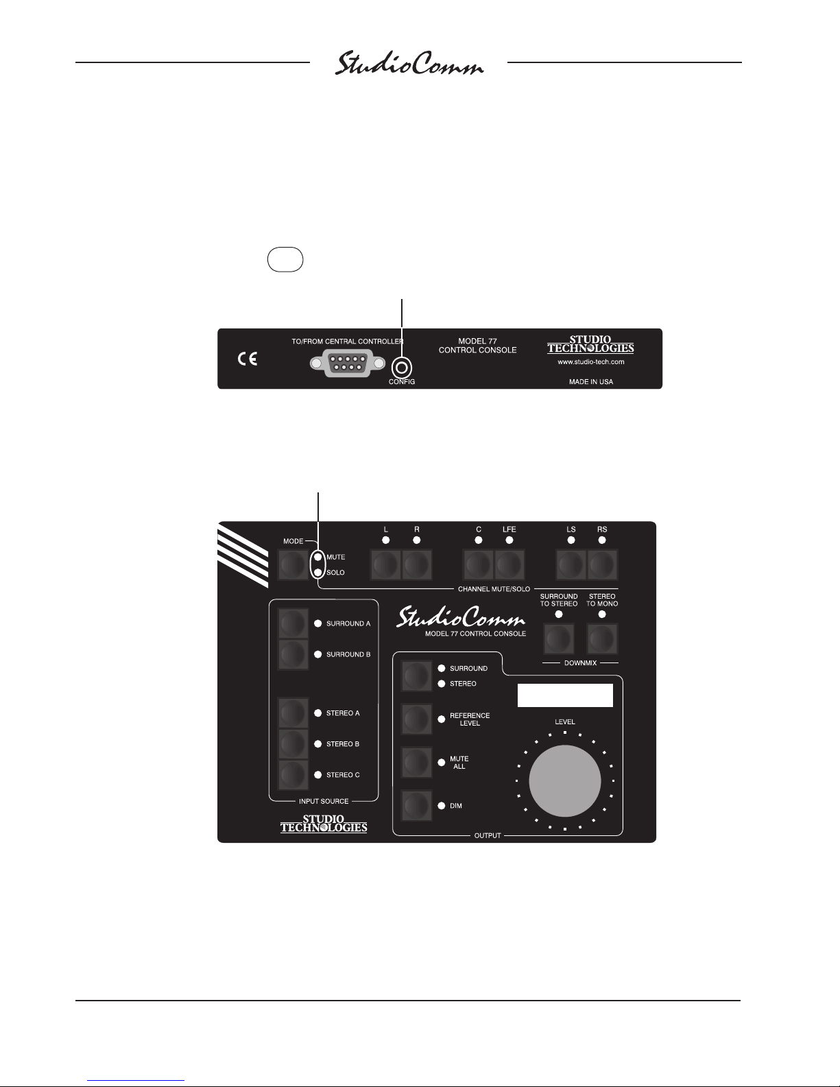
Configuration—Entering and Exiting Configuration Mode
Press and hold the configuration
button for 2 seconds to enter or
exit the configuration mode.
These LEDs will light alternately
when configuration mode is active.
Issue 3, October 2016 Model 760-02/77 User Guide
Page 24 Studio Technologies, Inc.
Page 25
for Surround
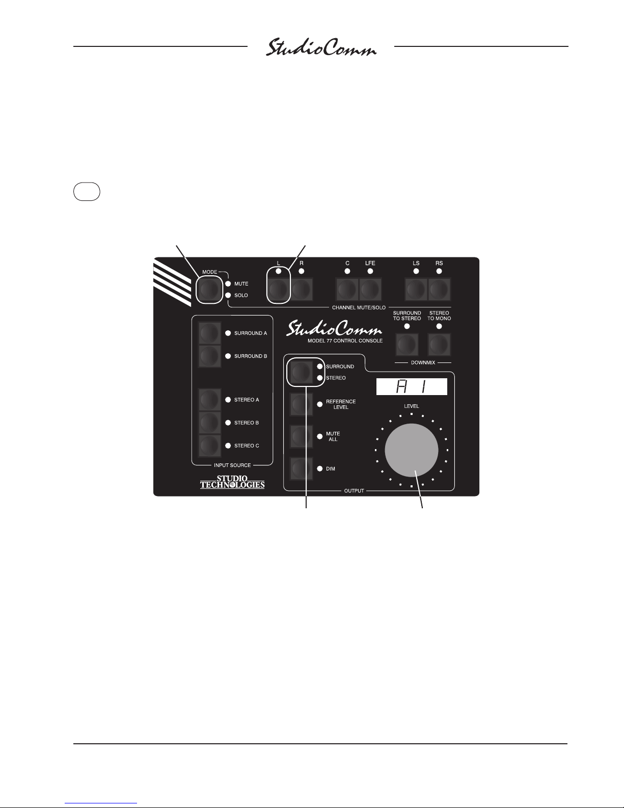
Configuration—Model 77 Device Address, Stereo Input C
Sample Rate Converter, and Stereo Monitor Output
Press and hold the Mute/Solo
button to display and configure the
Model 77’s device address, stereo
input C sample rate converter, and
stereo monitor output.
This LED displays the configuration of the
stereo input C sample rate converter
LED not lit means SRC is disabled;
(SRC).
LED lit means SRC enabled. Use the button
to change the configuration.
These LEDs display the status of the stereo
monitor output function. When LED Surround
is lit the function cannot be enabled. When LED
Stereo is lit the function can be enabled. Use the
button to change the configuration.
Default: Device address A1.
Stereo input C sample rate converter enabled.
Stereo monitor output can be enabled.
Note: The Model 77’s device address is the only parameter stored in the Model 77. All other parameters are stored
in the Model 760-02.
Model 760-02/77 User Guide Issue 3, October 2016
Studio Technologies, Inc. Page 25
Use the Level control to change this
specific Model 77’s device address.
Address can be either A1, A2, A3, or A4.
See Note below.
Page 26
for Surround
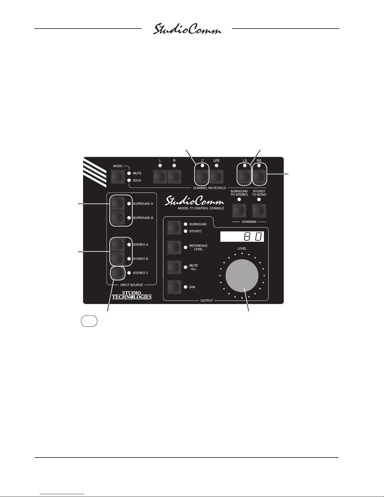
Configuration—Bass Management and Mute/Solo Bass
Management Mode
Use these
buttons to select
bass management low-pass
filter slope.
LED Surround A
lit means
24 dB-per-octave;
LED Surround B
lit means
12 dB-per-octave.
Use these
buttons to select
bass management high-pass
filter slope.
LED Stereo A
lit means
24 dB-per-octave;
LED Stereo B
lit means
12 dB-per-octave.
This LED displays the configuration of
the surround output bass management.
LED lit means surround output bass
management enabled; LED not lit means
surround output bass management
disabled. Use the button to change
the configuration. See Note below.
This LED displays the configuration of
the stereo output bass management.
LED lit means stereo output bass
management enab
means stereo output bass management
disabled. Use the button to change
the configuration. See Note below.
led; LED not lit
This LED displays
the configuration
of the mute/solo
bass mana
ment mode. LED
lit means mute/
solo functions
occur post-bass
management;
LED not lit means
mute/solo functions occur prebass management.
Use the button
to change the
configuration.
ge-
Press and hold the Stereo C button
to display and configure the bass
management and mute/solo bass
management mode settings.
Default: Surround output bass management disabled.
Stereo output bass management disabled.
Bass management low-pass filter slope 24 dB-per-octave.
Bass management high-pass filter slope 24 dB-per-octave.
Bass management crossover frequency 80 Hz.
Mute/solo pre-bass management mode.
Note: Bass management capability only a
Issue 3, October 2016 Model 760-02/77 User Guide
Page 26 Studio Technologies, Inc.
Use the Level control to select the
bass management crossover
frequency. Choices are 40, 50,
60, or 80 Hz.
vailable at sample rates of 44.1, 48, 88.2, and 96 kHz.
Page 27
for Surround
Configuration—Sync Source, Sync Input Termination, and
Audio-Synced-to-Video Sample Rate
This LED displays the configuration of the sync input termination.
LED not lit means sync input is not terminated; LED lit means terminated with 75 ohms. Use the button to change the configuration.
Press and hold
Use these buttons
to select the sync
source.
LED Surround B
lit means sync
input, video;
LED Stereo A lit
means sync input,
DARS;
LED Stereo B lit
means sync input,
word clock;
LED Stereo C
lit means L/R of
currently selected
input.
the Stereo to
Mono button to displa
and select the
sync source
sync input
termination, and
audio-syncedto-video-sample
rate.
y
,
Default: Sync source is L/R of currently selected input.
Sync input terminated.
Audio-synced-to-video sample rate 48 kHz.
Model 760-02/77 User Guide Issue 3, October 2016
Studio Technologies, Inc. Page 27
Use the level control to adjust the audiosynced-to-video sample rate. Available
sample rates are 32, 44.1, 48, 88.2, 96,
176.4, and 192 kHz.
Page 28
for Surround
Configuration—Reference Level
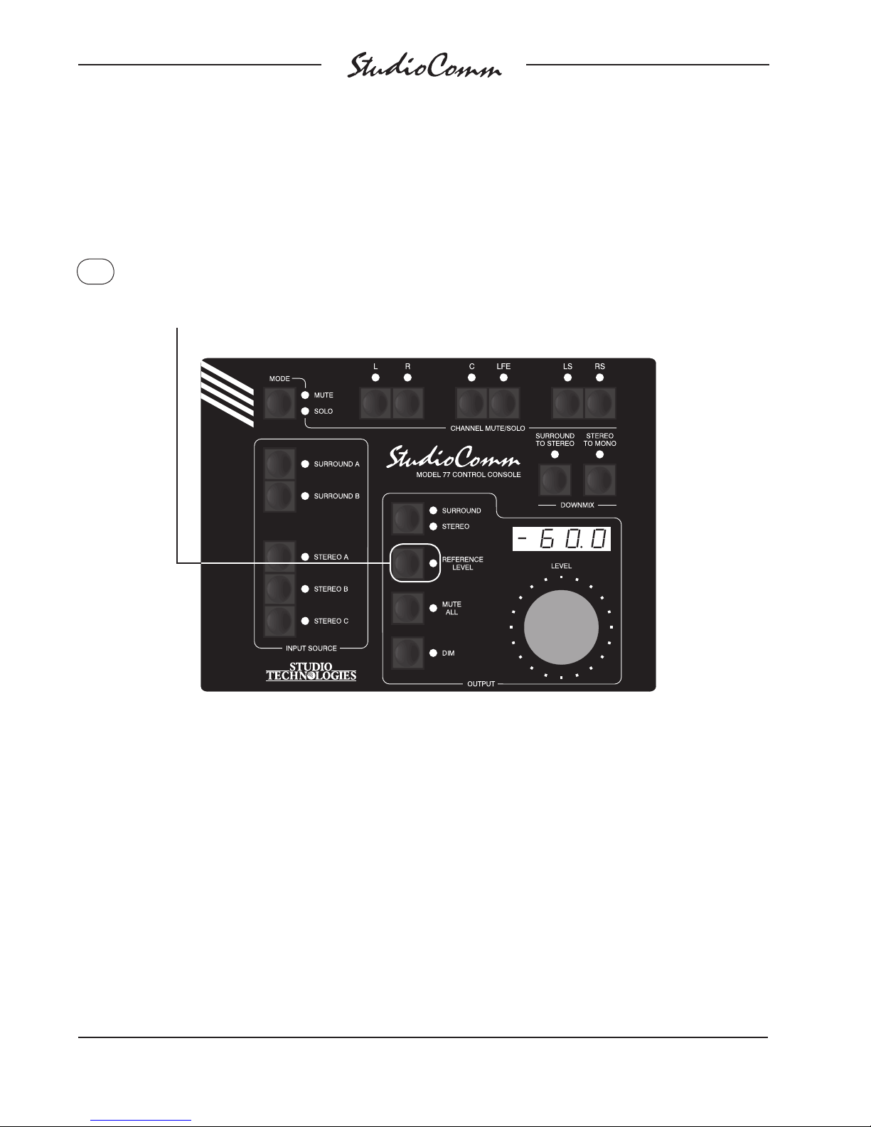
Press and hold the Reference Level button for 5 seconds to take a “snapshot”
of the level control’s setting at the time configuration mode was entered. The
Reference Level LED will flash when the button is initially pressed and then
light steadily when the “snapshot” has been taken. See Note below.
Default: Reference level set for –60.0 dB monitor output level.
Note: The 5-second button-press delay is a safety feature ensuring that the reference level will not be accidently
changed. To permanently store the new value, you must still exit the configuration mode.
Issue 3, October 2016 Model 760-02/77 User Guide
Page 28 Studio Technologies, Inc.
Page 29
for Surround
Configuration—Overall Display Mode, Reference Level
in dB SPL, and Auto Reference Level Off
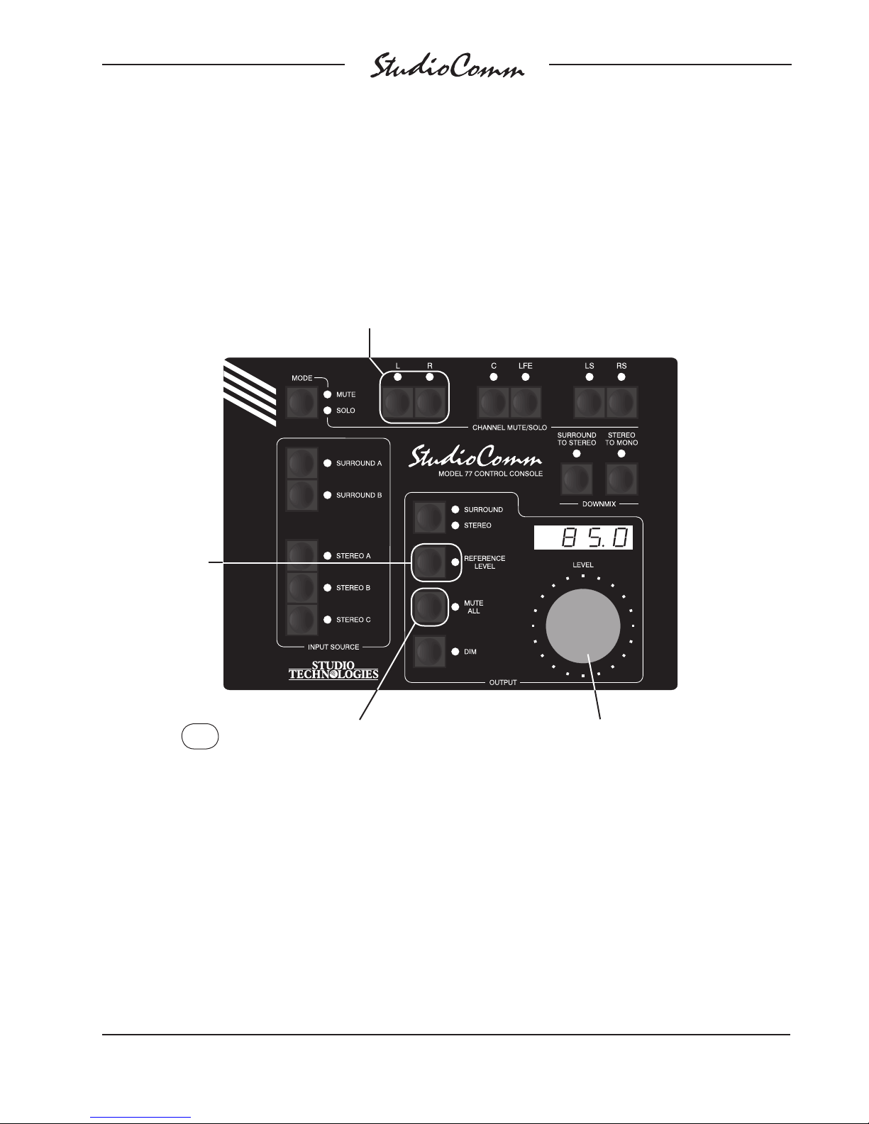
When the Mute All button is pressed, use the Channel Mute/Solo
L and R buttons to select the overall display mode. LED L lit
means attenuation mode is selected; LED R lit means SPL mode
is selected. Use the buttons to change the configuration.
When the Mute
All button is
pressed, use the
Reference Level
button to enable
or disable auto
reference level
off. When the
Reference Level
LED is lit auto
reference level
off is enabled.
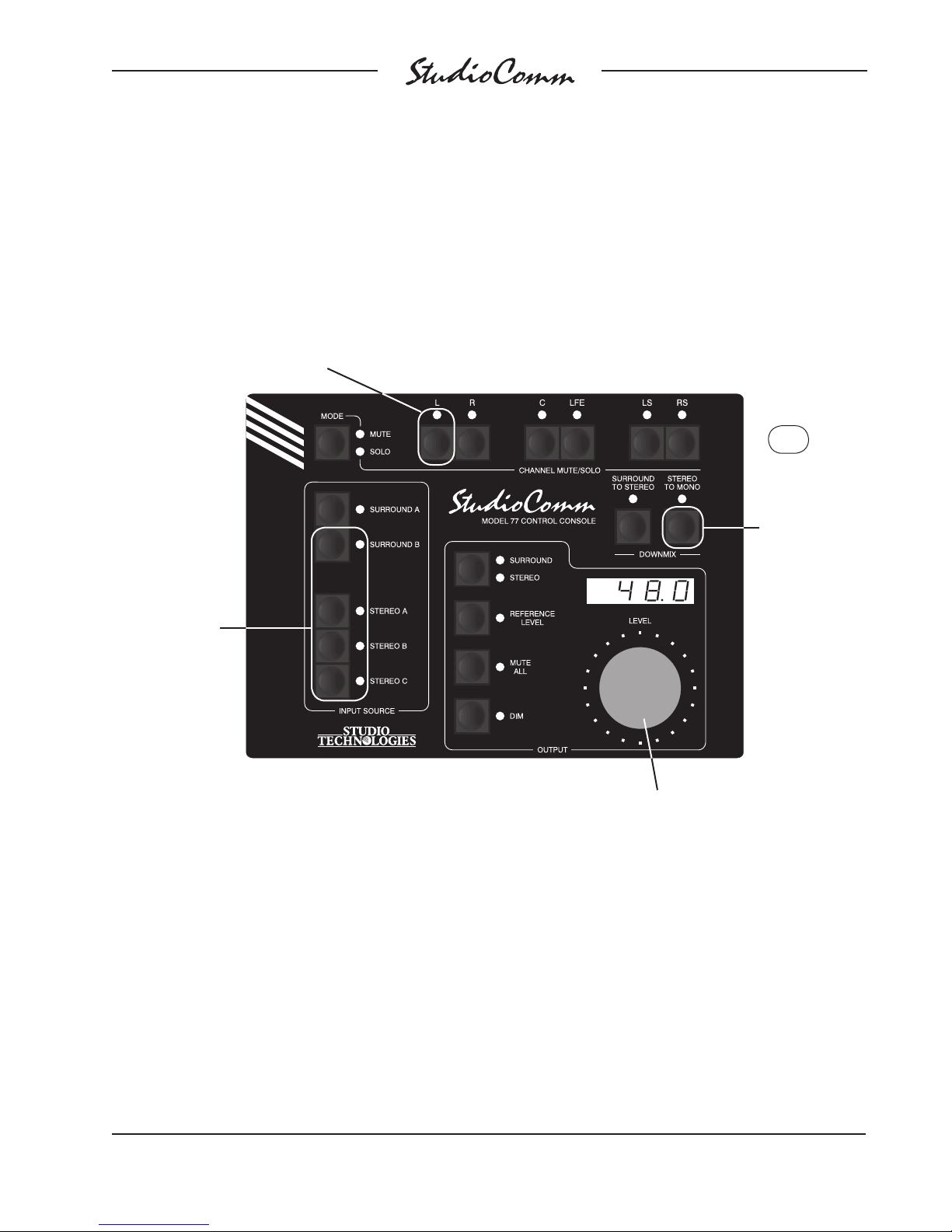
Press and hold the Mute All b
Default: Attenuation display mode selected.
85.0 dB SPL reference level.
Auto ref level off disabled.
Model 760-02/77 User Guide Issue 3, October 2016
Studio Technologies, Inc. Page 29
y and set the overall display mode,
displa
the reference level in dB SPL, and auto
reference level off.
utton to
When the Mute All button is pressed,
use the Level control to adjust the
reference level in dB SPL.
Page 30
for Surround
Configuration—Dim Level, Remote Mute All, and Remote Dim
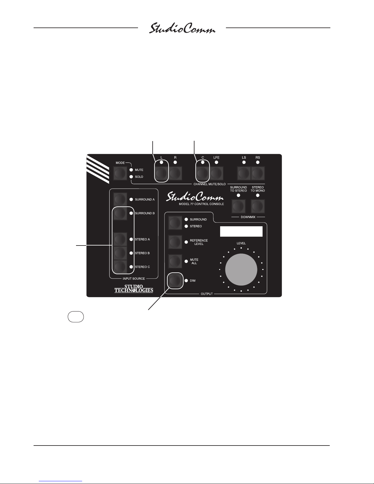
This LED displays the configuration of
remote mute all. LED not lit means
remote mute all is disabled; LED lit
means enabled. Use the button to
change the configuration.
Use these buttons
to select dim level.
LED Surround B lit
means –10 dB;
LED Stereo A lit
means –15 dB;
LED Stereo B lit
means –20 dB;
LED Stereo C lit
means –25 dB.
This LED displays the configuration
of remote dim. LED not lit means
remote dim is disab
means enabled. Use the button to
change the configuration.
led; LED lit
Press and hold the Dim button to
display and select the dim level,
remote mute all, and remote dim.
Default: –20 dB dim level.
Remote dim enabled.
Issue 3, October 2016 Model 760-02/77 User Guide
Page 30 Studio Technologies, Inc.
Remote mute all enabled.
Page 31
for Surround
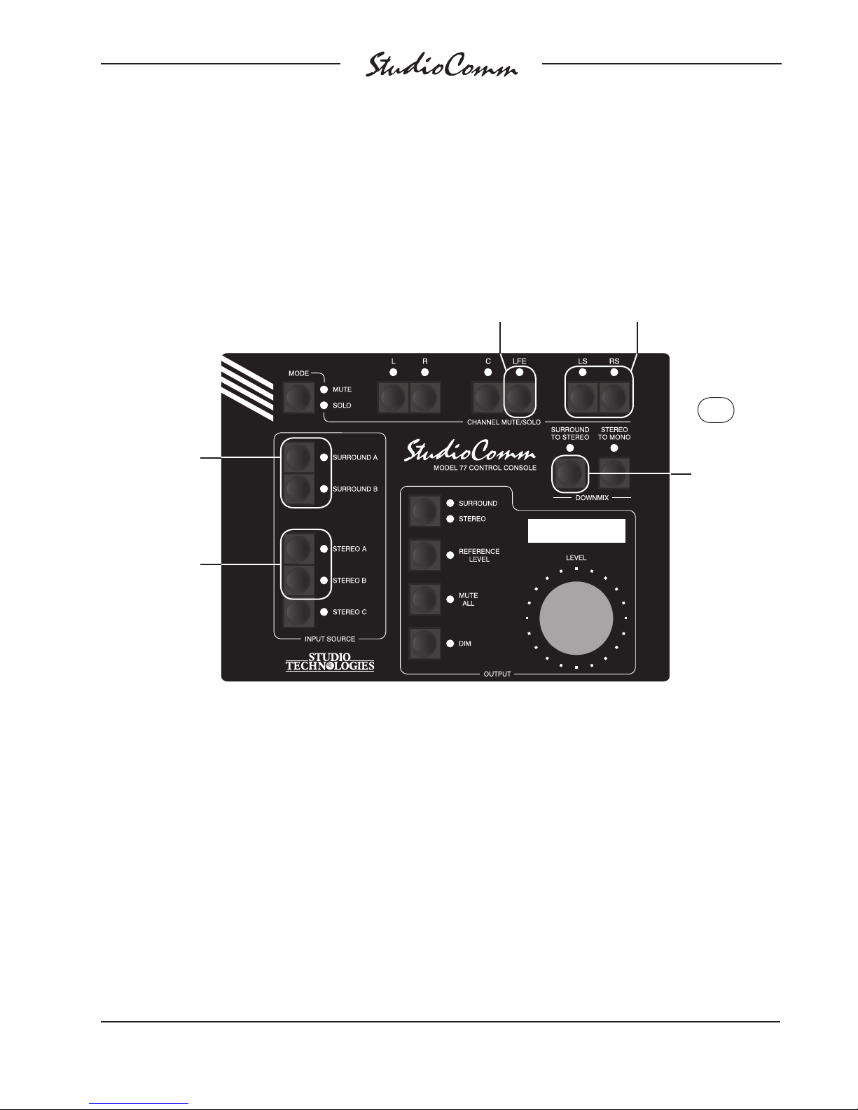
Configuration—Surround to Stereo Downmix Levels
Use these buttons to select
Use these buttons
to select the level
change for the left
and right channels
when the surround
to stereo downmix
function is active.
LED Surround A
lit means 0 dB;
LED Surround B
lit means –3 dB.
Use these buttons
to select the level
change for the left
surround and right
surround channels
when the surround
to stereo downmix
function is active.
LED Stereo A
lit means –3 dB;
LED Stereo B
lit means –6 dB.
Use this button to select the level
change for the LFE channel when the
surround to stereo downmix function is active. LED not lit means full
atten
uation; LED lit means –6 dB.
the level change for the center
channel when the surround to
stereo downmix function is
active. LED LS lit means –3 dB;
LED RS lit means –6 dB.
Press and hold
the Surround to
Stereo b
to display and
confirm the surround to stereo
downmix levels.
utton
Default: L and R channel level change 0 dB when surround to stereo downmix function active.
LS and RS channel level change –3 dB when surround to stereo downmix function active.
C channel level change –6 dB when surround to stereo downmix function active.
LFE level change full attenuation when surround to stereo downmix function active.
Model 760-02/77 User Guide Issue 3, October 2016
Studio Technologies, Inc. Page 31
Page 32
for Surround
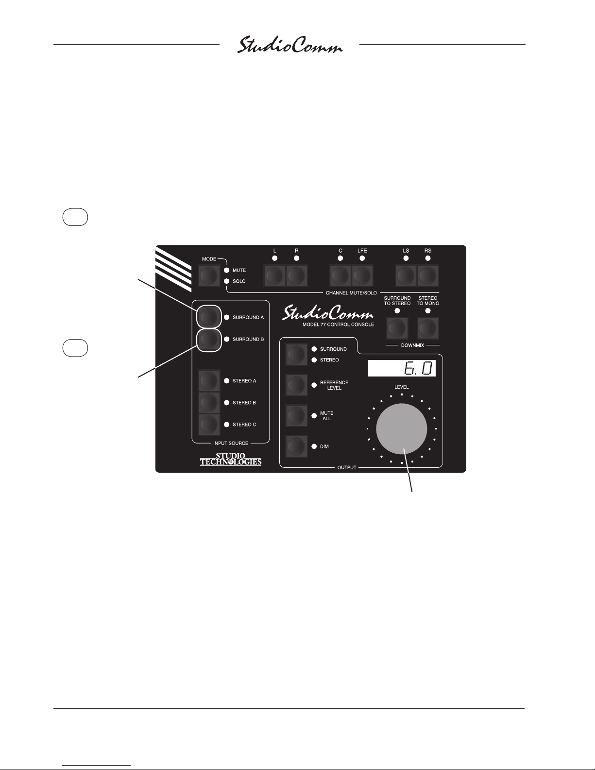
Configuration—Channel Pop Solo Mode Offset Levels
Press and hold
the Surround A
b
utton to display
and select the
channel pop solo
up offset le
vel.
Press and hold
the Surround B
button to display
and select the
channel pop solo
down offset level.
Default: 6.0 dB channel pop solo up offset level.
–6.0 dB channel pop solo down offset level.
When the Surround A button is pressed, use the level
control to adjust the channel pop solo up offset level.
The range is 0.0 to 12.0 in 0.5-dB steps.
When the Surround B button is pressed, use the level
control to adjust the channel pop solo down offset level.
ange is –0.0 to –12.0 in 0.5-dB steps and full mute.
The r
Full mute is selected by adjusting the level control past
–12.0, at which point the display will show – – – –.
Issue 3, October 2016 Model 760-02/77 User Guide
Page 32 Studio Technologies, Inc.
Page 33
for Surround
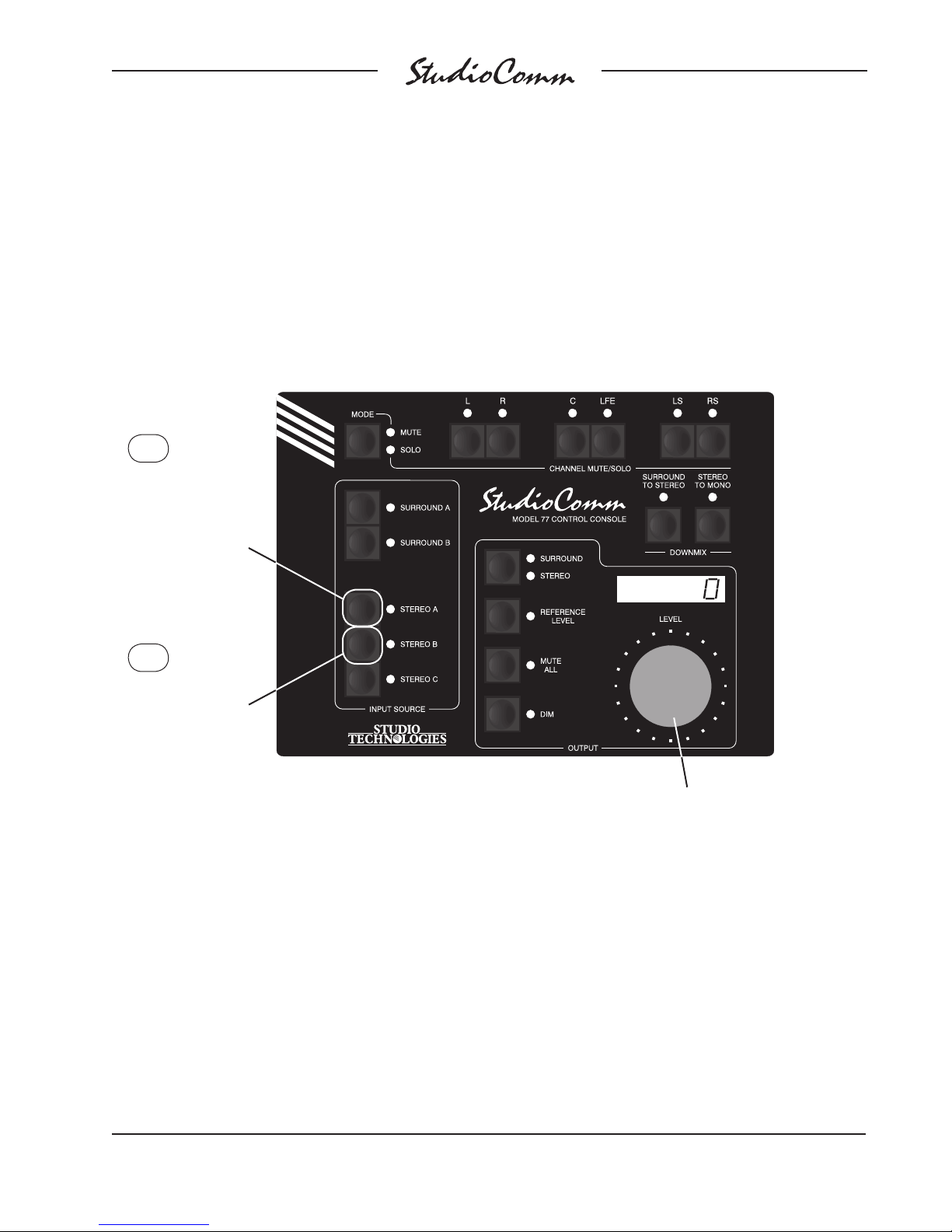
Configuration—Input Delay Settings
Press and hold the
Stereo A b
display and select
input delay A.
utton to
Press and hold the
Stereo B button to
display and select
input delay B.
Default: Input delay 0 ms for both A and B.
Use the level control to adjust the input delay.
Range is from 0 to 340. The display shows
delay in milliseconds at 48 kHz sampling
rate. The value is scaled up or down for other
sample rates.
Model 760-02/77 User Guide Issue 3, October 2016
Studio Technologies, Inc. Page 33
Page 34
for Surround
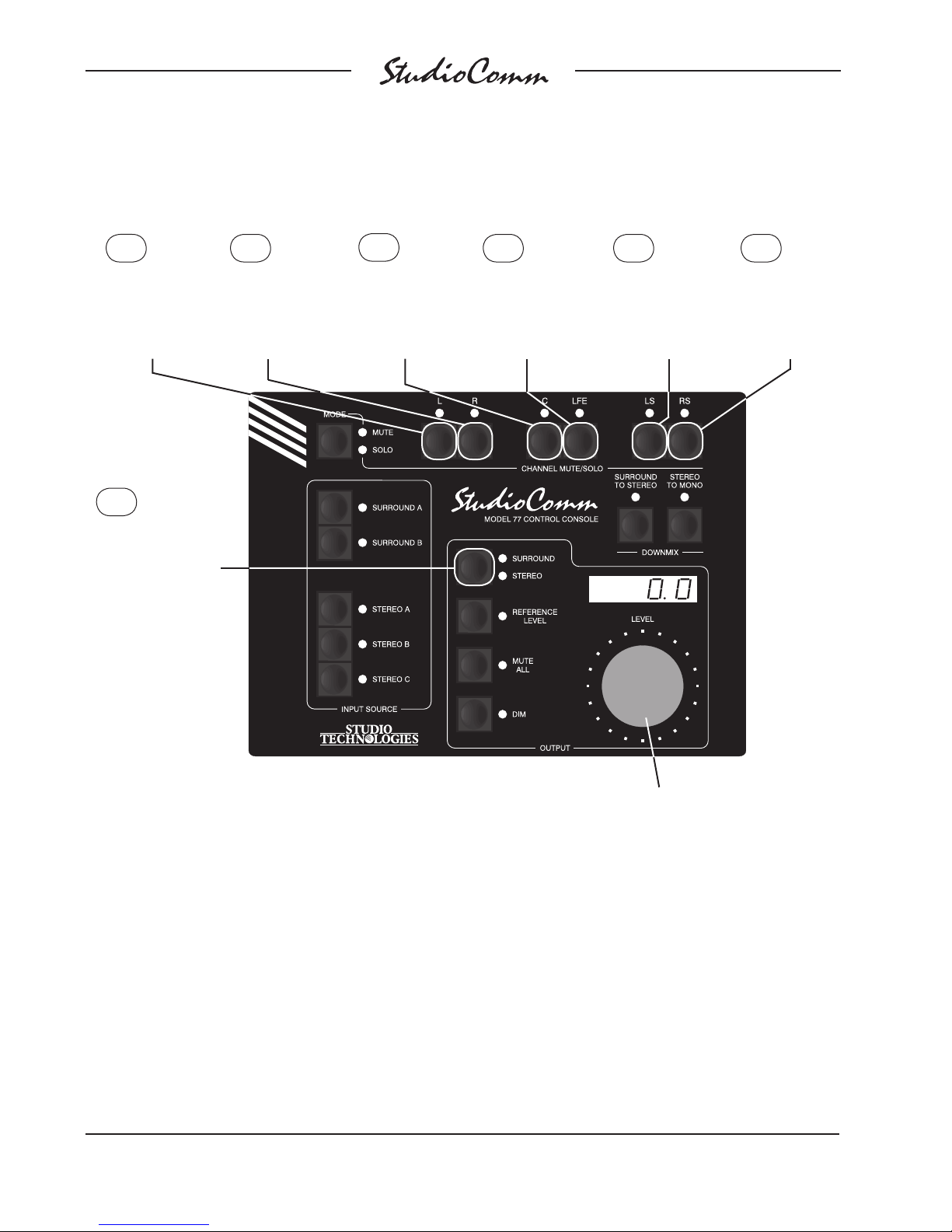
Configuration—Monitor Output Level Offsets
Press and hold
the L b
utton
to configure
the surround L
level offset.
Press and hold both
the L and Surround/
Stereo buttons to
configure the stereo
L level offset.
Press and hold
both the R and
Surround/Stereo
buttons to configure
the stereo R level
offset.
Press and hold
the R button
to configure
the surround R
level offset.
Press and hold
the C button to
configure the
surround C
level offset.
Press and hold
the LFE button
to configure the
surround SUB
level offset.
Press and hold
the LS button to
configure the
surround LS
level offset.
Press and hold
the RS button
to configure the
surround RS
level offset.
Default: 0.0 dB surround monitor output level offsets.
0.0 dB stereo monitor output level offsets.
Issue 3, October 2016 Model 760-02/77 User Guide
Page 34 Studio Technologies, Inc.
Use the level control to adjust the monitor output level
offsets. The range is –12.0 to 12.0 in 0.5-dB steps.
Page 35
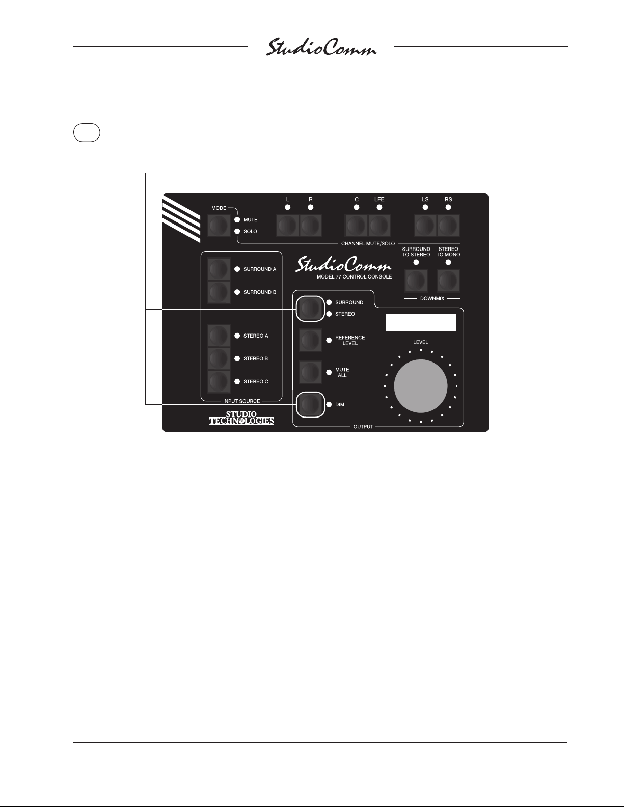
for Surround
Configuration—Restore Factory Defaults
Press and hold both the Surround/Stereo and Dim buttons for 5 seconds
to restore Model 77 factory defaults. Once defaults have been restored,
the associated LEDs will light. After the buttons are released, configuration
mode will be exited and normal operation will resume. See Note below.
Factory Defaults:
Device address A1.
Stereo input C sample rate converter enabled.
Stereo monitor outputs can be enabled.
Surround output bass management disabled.
Stereo output bass management disabled.
Bass management low-pass filter slope 24 dB-per-octave.
Bass management high-pass filter slope 24 dB-per-octave.
Bass management crossover frequency 80 Hz.
Mute/solo pre-bass management mode.
Sync source is L/R of currently selected input.
Sync input terminated.
Audio-synced-to-video sample rate 48 kHz.
Reference level set for –60.0 dB monitor output level.
Attenuation display mode selected.
85.0 dB SPL reference level.
Auto reference level off disabled.
–20 dB dim level.
Warning: Each Model 77 unit must have a unique address. Restoring factory defaults will reset only this specific
Model 77 to device address A1. If another connected unit is already configured for address A1, normal system
operation will stop.
Note: The 5-second button-press delay is a safety feature ensuring that the factory defaults will not be accidently
restored.
Remote mute all enabled.
Remote dim enab
L and R channel level change 0 dB when surround to
stereo downmix function active.
LS and RS channel level change –3 dB when surround to
stereo downmix function active.
C channel level change –6 dB when surround to stereo
downmix function active.
LFE level change full attenuation when surround to stereo
downmix function active.
6.0 dB channel pop solo up offset level.
–6.0 dB channel pop solo down offset level.
Input delay 0 ms for both A and B.
0.0 dB surround monitor output level offsets.
0.0 dB stereo monitor output level offsets.
led.
Model 760-02/77 User Guide Issue 3, October 2016
Studio Technologies, Inc. Page 35
Page 36

for Surround
Operation
Now that you’ve installed and configured
the system, you’re ready to go. You should
find operation very easy. However, taking
time to study this section of the user guide
may prove valuable.
Upon AC mains power up the system
will return to the last operating condition,
including the selected source, downmix
modes, etc. As a precaution, however, the
monitor output level will always return to
its minimum value. The rotary level control
or the reference level button must then be
used to return the system to the desired
monitor output level.
Model 760-02 Central
been connected. Two system functions can
also be controlled by means of the remote
control inputs.
Model 77 Control Console
To make things easy to describe, the Model 77’s operator functions are divided into
six main groups: input source selection,
downmix, monitor output general functions,
channel mute/solo, display and display
mode, and remote control inputs.
Any change made to any one Model 77
unit will be reflected in the LEDs and displays on all the connected units. Note that
all control consoles function simultaneously—there is no priority of one unit over
the others.
Controller
The Model 760-02’s front panel contains
two LEDs. The control console status LED
will light whenever the Model 760-02 is
communicating with the one or more connected Model 77 or Model 71 units. If the
control console status LED is flashing it
indicates that the DC power output supporting the control consoles is in a short
circuit or over-current condition. The control console status LED will not light when
a Model 77 is in the configuration mode
or when the Model 77 is going through its
power-up sequence.
The sync status LED will light whenever
a valid timing reference signal is being
received by the Model 760-02. A flashing
sync status LED indicates that a valid sync
signal is not being received.
Control Consoles
StudioComm for Surround operation is
controlled using the up to four Model 77
or Model 71 Control Consoles that have
Input Source Selection
To select an input source press one of the
five input source buttons. The corresponding LED will light to indicate that the input
has been selected. Typically, only one
source will be selected for monitoring at
any one time. However, input stereo C can
be selected by itself, or mixed (summed)
with one of the other four inputs. To accomplish this is easy: simply press and hold
input stereo C then press the button associated with the other desired input source.
The two corresponding LEDs will light.
Alternately, press and hold the first desired
input (other than input stereo C) and then
press the input stereo C button.
It’s possible (although unlikely) that selecting an input will result in the mute all
function being enabled and an Err3 message being displayed. This would indicate
a conflict between the sample rate of the
selected input source and the bass management function. (Operation of the bass
management function requires the source
Issue 3, October 2016 Model 760-02/77 User Guide
Page 36 Studio Technologies, Inc.
Page 37

for Surround
to have a sample rate of 44.1, 48, 88.2, or
96 kHz.) Selecting a source with a sample
rate of 44.1, 48, 88.2, or 96 kHz will resolve the issue and normal operation will
resume. Refer to the Technical Notes section of this user guide for additional details.
Downmix
Two downmix functions allow users to perform “real-world” audio format compatibility
checks. One function allows a surround
(5.1) signal to be “folded down” (mixed) to
stereo. The other allows a stereo signal to
be converted to mono. Using the downmix
functions simply requires pressing the desired button. The buttons are set to always
“latch” the functions on and off. An LED is
located adjacent to each button and lights
whenever its respective function is active.
The downmix function will impact the surround and stereo monitor outputs.
A specific downmix function can only be
enabled when it is applicable for the currently selected input source. This means
that the surround to stereo downmix function can only be enabled when surround
input A or B is selected.
The Model 77 associates the state of the
downmix functions with the currently selected input. For example, if surround input
A is the selected input source and the surround to stereo downmix function is enabled, this condition will be “remembered”
when switching to one of the stereo input
sources. Upon returning to surround input
A, the surround to stereo downmix function
will again become active. For details on the
exact actions performed by the downmix
functions refer to Appendix C at the end of
this user guide.
Surround to Stereo
When the surround to stereo downmix function is enabled the LS, RS, and C channels associated with a surround source are
combined (“folded down”) with the L and
R signals to create a 2-channel stereo (left
and right) signal. And, depending on the
system’s configuration, the LFE channel
may also be combined with the L and R
signals. The resulting stereo signal, sometimes known as LtRt, is routed to the L and
R surround monitor output channels. Also,
whenever the surround to stereo downmix
function is enabled the C, LS, RS, and SUB
monitor output channels are muted. By utilizing this downmix function phase relationships and inter-channel level issues can be
quickly observed.
Stereo to Mono
The stereo to mono downmix function combines the L and R audio channels to create a single-channel monaural signal. This
signal is sent out the C surround monitor
output channel while the L, R, LS, RS, and
SUB monitor output channels are muted.
When a surround source has been selected
for monitoring, the surround to stereo downmix function will automatically enable whenever the stereo to mono downmix function
is enabled. This ensures that a user will
hear a mono signal created by folding down
all channels associated with the selected
surround input.
Monitor Output General
Functions
Four buttons and one rotary control are associated with the surround and stereo monitor output functions. The buttons control
selection of the surround or stereo outputs,
as well as the reference level, mute all, and
Model 760-02/77 User Guide Issue 3, October 2016
Studio Technologies, Inc. Page 37
Page 38

for Surround
dim functions. The rotary level control is
used to manually set the level of the surround and stereo monitor outputs.
Surround and Stereo Outputs
The surround/stereo function allows selection between two different loudspeaker
systems. When the surround output is
selected the six channels associated with
the surround monitor output are active. The
two channels associated with the stereo
monitor output are muted. When the stereo
output is selected the left (L) and right (R)
channels associated with the stereo monitor output become active; the six channels
of the surround monitor output will mute.
Remember that the Model 77 Control
Console can be configured to disable the
surround/stereo button. If the button is
pressed and the stereo monitor output is
not selected, this must be the case!
Display Current Sample Rate
The surround/stereo monitor output select
button is also used to display the system’s
current sample rate value. Pressing and
holding the surround/stereo button will
cause the current sample rate value to
be displayed: 32.0, 44.1, 48.0, 88.2, 96.0,
176.4, or 192.0. This can be useful during
troubleshooting or just for general interest.
Once the button is released normal display
operation will resume.
will light whenever the function is active.
The 4-digit display will indicate the reference output level. Note that the system’s
default reference level is –60.0 dB so “out
of the box” the Model 77 will display –60.0
when reference level mode is enabled.
How the rotary level control functions
whenever the reference level mode is active depends on a configuration setting.
If the auto reference level off function is
disabled turning the rotary level control will
have no impact on the reference level function; it will remain active. If the auto reference level off function has been enabled
turning the rotary level control will cause
the reference level function to automatically turn off.
The LED associated with the reference
level button can also serve as a calibration aid. If the reference level mode is not
active, whenever the surround or stereo
monitor output levels are precisely the
same as that stored for the reference value
the reference level LED will flash. This
exact level can be reached through the use
of the rotary level control, either by itself
or through the setting of the rotary level
control in conjunction with the dim function.
Whatever path the selected monitor output
takes to reach the reference level value, it
will cause the reference level LED to flash.
Mute All
Reference Level
The reference level button sets the level of
the surround and stereo monitor outputs to
a preset value. Technical personnel, using
a sound-pressure-level (SPL) meter and
precision signal source, should have set
this level to meet the requirements of the
specific monitoring environment. The LED
associated with the reference level button
Issue 3, October 2016 Model 760-02/77 User Guide
Page 38 Studio Technologies, Inc.
Pressing the mute all button causes the
channels associated with the monitor outputs to mute. The 4-digit display indicates
the mute condition by showing four dashes
(– – – –). The mute all button is always set
to “latch” the function on and off. The LED
associated with the mute all button will
light whenever mute all is active. Note that
if mute all is enabled via the remote mute
all function, the mute all LED will flash.
Page 39

for Surround
Dim
The dim function is provided for user convenience, allowing the monitor output level to
be reduced by a fixed amount. The Model
77’s configuration mode allows the dim level
to be selected from among four choices:
–10.0, –15.0, –20.0, or –25.0 dB. Pressing
the dim button will enable the function. The
dim button is always set to “latch” the function on and off. The 4-digit display, when
selected for output level mode, will indicate the revised monitor output level. If the
requested “dimmed” output level is equal to
or less than –96.0 dB, the selected monitor
output will go into full mute and the display
will show four dashes (– – – –). When dim
is active the monitor output level reduction
will apply no matter whether the level is
being set by the rotary level control or by
the reference level button. The LED associated with the dim button will light whenever
dim is active. If dim mode is enabled via the
remote dim function the dim LED will flash.
It’s worth using a few sentences to discuss the auto dim off function. Whenever
dim is enabled due to the dim button being pressed, and the rotary level control is
active (reference level mode is not active),
changing the setting of the rotary level
control will automatically turn off dim. The
auto dim off function is a unique attempt
at protecting the aural health of users. No
longer will there be a heart-stopping blast of
audio when the dim button is pressed, supposedly to enable dim, but actually turning
dim off because it was already enabled. It’s
hard to explain unless you’ve experienced
this in person—trust us, this situation can
and does happen!
Note that the auto dim off function is not
active whenever dim is enabled due to
the remote dim function being active. This
allows remote control equipment, such
as a talkback system, to reliably dim the
selected monitor output.
Rotary Level Control
The rotary level control is used to manually adjust the level of the selected monitor output; surround or stereo. The level
control provides the ability to adjust the
monitor output level over a 70-dB range.
Technically the rotary level control is a 24step-per-revolution mechanical encoder.
The amount of level change in dB per
step (“click”) will depend on how quickly
the control is turned. When rotated slowly,
each step represents a 0.5-dB change in
level. In this case, to traverse the entire
level range would require rotating the control more than five full turns. But the Model
77’s software detects when the control is
rotated more quickly and increases the
amount of level change in dB per step. A
little experimentation will allow the user to
acquire a good “feel” for how best to use
the control.
The reference level LED will flash when
the rotary level control sets the output level
to be the same as the stored reference
level. Whenever the rotary level control
attempts to set the output level for less
than –70.0 dB, the selected monitor output
channels will automatically mute. As previously discussed, the 4-digit display indicates the mute condition by showing four
dashes (– – – –).
If the mute all function is active the rotary
level control won’t have an impact on the
monitor output level. It’s also not active
whenever the reference level function is
active, except if the auto reference level off
function has been enabled.
Model 760-02/77 User Guide Issue 3, October 2016
Studio Technologies, Inc. Page 39
Page 40

for Surround
Channel Mute/Solo
The channel mute/solo functions allow
specific channels to be selected for individual or group mute or “solo” monitoring.
The functions impact the selected monitor
output, surround or stereo, taking place
electrically “after” the input source selection,
input delay, downmix, and level control functions. The relationship between the mute/
solo function and the bass management
resources will depend on how the system
has been configured.
The mute/solo mode button and the six
channel mute/solo buttons, along with associated LEDs, work together to provide
excellent operating flexibility. The channel
mute/solo mode button allows the user to
select between the mute and solo functions.
Going from mute mode to solo mode, or
vice-versa, clears all active mutes or solos.
Pressing the mode button twice is a legitimate means of quickly clearing muted or
soloed channels. To mute or solo a channel
simply requires pressing one of the channel
mute/solo buttons. The buttons function in a
press-to-enable/press-to-disable “latching”
mode. Multiple channels can be muted or
soloed at the same time. The LED associated with any muted or soloed channels is
used to indicate that the function is active.
In most cases the mute/solo function will
be configured to act in a pre-bass management signal flow, creating an “input” mute/
solo function. In this case soloing one channel when bass management is enabled will
result in audio content being reproduced in
both the soloed channel and the subwoofer
monitor output channel. Should the function
be configured for post-bass management
mode soloing a channel will result in only
that specific monitor output channel reproducing the audio content.
Selecting the Solo Mode
As previously discussed in this user guide,
solo operation can be selected between
normal and channel pop. When the normal solo mode has been enabled the solo
LED will light steadily. When the channel
pop solo mode is enabled the solo LED will
flash. It’s easy to change from normal to
pop solo, and vice-versa. Simply press and
hold the mode button and use the surround
to stereo button to select the desired solo
mode. The LED associated with the surround to stereo button displays the active
mode. Refer to Figure 10 for details. The
selected mode will be stored in nonvolatile
memory so a power-down/power-up cycle
will not change the selection.
Input Delay
Two input delay settings, A and B, can be
selected and saved during system configuration. These are provided for aligning
the audio input signals with latencies associated with video processing and display
systems. During normal operation of the
StudioComm system the active input delay,
A or B, can be selected. The channel mute/
solo button, stereo to mono button, and 4digit display are used to display and select
the input delay. When the mute/solo button
is pressed and held the LED associated
with the stereo to mono button indicates
whether input delay A or input delay B is active. The 4-digit display will show the active
delay time in milliseconds. While pressing
and holding the mute/solo button the stereo
to mono button can be pressed to change
the selected input delay. Refer to Figure 10
for details. The selected input delay will be
stored in nonvolatile memory so a powerdown/power-up cycle will not change the
selection.
Issue 3, October 2016 Model 760-02/77 User Guide
Page 40 Studio Technologies, Inc.
Page 41
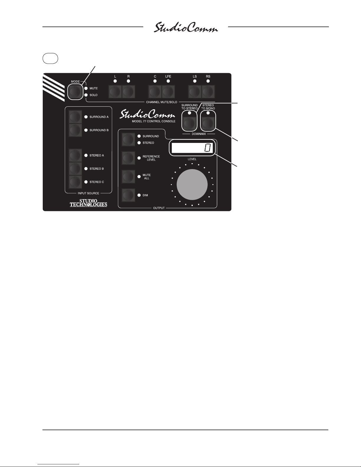
for Surround
During normal operation, press and hold the Mute/Solo button
to view and change the solo mode and input delay settings.
This LED displays the current setting
of the solo mode. LED not lit means
normal; LED lit means channel pop.
Press the button to change the mode.
This LED displays the current
setting of the input delay.
LED not lit means input delay A
is selected; LED lit means input
delay B is selected. Press the
button to change the setting.
The display shows the currently
selected input delay in milliseconds.
Figure 10. Solo mode and input delay settings
Display and Display Mode
The Model 77’s 4-digit LED display shows
the monitor output level as either the
amount of attenuation or the sound pressure level (SPL). Both will indicate level in
dB. What the digits actually represent will
depend upon how the Model 77 has been
configured.
Display in dB of Attenuation
If configured for the attenuation mode the
display will show the monitor output level
as an attenuation value in reference to
the maximum output. This is in the form
of 0.5-dB steps less than the maximum of
0.0 dB. So a display of –40.5 would indicate
that the selected surround or stereo monitor output is set to be 40.5 dB below the
maximum level. As the rotary level control
is moved counterclockwise the output level
will go down and the indicated value will
get more negative.
Display in dB SPL
If the Model 77 is configured to display the
monitor output level in dB SPL, the 4-digit
display will always show the output level
in positive numbers. These numbers are
intended to represent the sound pressure
level in dB SPL, a figure that should directly relate to the actual sound pressure
level that the selected surround or stereo
loudspeaker system is presenting to users.
(Typically, the level value would actually
be in dBC, the C-weighted sound pressure
level.) When the reference level button is
enabled, or the rotary level control is set so
that the reference level has been reached,
the display will typically show something
in the range of 82 to 87 dB. Assuming that
the monitoring environment has been correctly calibrated, this would indicate that an
average listening level of 85 dB, for example, had been achieved.
Model 760-02/77 User Guide Issue 3, October 2016
Studio Technologies, Inc. Page 41
Page 42

for Surround
Channel Pop Solo Display
As has been previously discussed, the
channel pop solo mode offers a unique way
of sonically highlighting an individual channel. A channel selected for soloing in this
mode will have its level increased while the
other non-soloed channels will be reduced
in level. To highlight this condition the letters POP will appear in the 4-digit display
whenever a channel is actively being soloed
in the channel pop solo mode. This ensures
that a user will understand that the monitor
output no longer represents the true interchannel level relationships.
Remote Control Inputs
As previously discussed in the Installation
section of this user guide, two remote control signals can be connected to the Model
760-02 and then configured for operation.
The functions are remote mute all and
remote dim. When an external signal activates remote mute all the LED on the Model
77 associated with the mute all button will
flash. If mute all was already active when
the remote mute all function is activated,
the LED will change from being steadily lit
to flashing.
When an external signal activates remote
dim the LED on the Model 77 associated
with the dim button will flash. If dim was already active when remote dim is activated,
the LED will change from being steadily lit
to flashing.
LEDs, provide access to the dim and reference level functions. A status LED lights
steadily whenever normal Model 71 operation is taking place.
Any changes made using the Model 71’s
rotary level control and buttons will be
reflected in the appropriate LEDs and displays on all the connected Model 77 and
Model 71 units. And, as expected, changes
made using a Model 77 will be reflected in
the Model 71’s LEDs.
In some applications it may be desirable to
disable operation of a Model 71’s dim and
reference buttons. An example could be
where non-technical personnel are allowed
only to use the rotary level control. A configuration parameter, previously described
in the Model 71 Control Console Configuration section, allows button operation to
be disabled.
Rotary Level Control
The rotary level control is used to manually
adjust the monitor output level. Its operating characteristics are identical to those of
the Model 77 Control Console, discussed
earlier in this section.
Dim
The dim function allows the monitor output
levels to be reduced by a fixed amount.
Its operating characteristics are identical
to those of the Model 77 Control Console,
discussed earlier in this section.
Model 71 Control Console
The Model 71 Control Console provides a
rotary level control and a limited number of
pushbutton switches and LEDs for control
and status display. The rotary level control
allows adjustment of the monitor output
level. Two buttons, along with associated
Issue 3, October 2016 Model 760-02/77 User Guide
Page 42 Studio Technologies, Inc.
An indication is provided should the dim
button be pressed when button operation
has been disabled. Its associated LED will
flash briefly but no operating change will
occur. The LED will continue to display the
status of the dim function as selected by
other Model 77 and Model 71 units.
Page 43

for Surround
Reference Level
The reference level button sets the monitor
output level to a preset values. The operating characteristics are identical to those of
the Model 77 Control Console, discussed
earlier in this section.
An indication is provided should the reference button be pressed when button
operation has been disabled. The associated LED will flash briefly but no operating
change will occur. The LED will continue
to display the status of the reference level
function as selected by other Model 77 and
Model 71 units.
Technical Notes
Loss of Sync
The Model 760-02 relies on an external
timing reference (sync) source for proper
operation. This can be in the form of an
AES3, word clock, DARS (AES11), bi-level
video, or tri-level video reference signal. In
most cases the sync signal will be connected to the sync input BNC connector
located on the Model 760-02’s back panel.
Alternately, a configuration choice allows
the L/R input of the AES3 source currently
selected for monitoring to also serve as
the system’s timing reference. Whenever
a valid sync signal has been connected
to the Model 760-02 the sync status LED,
located on the unit’s front panel, will light.
The sample rate of the monitor output
channels will reflect the rate of the sync
input and, if a video sync source is utilized,
the configured rate.
cease normal operation, instead alternating between the words no and sync. When
a valid sync signal is again connected
the Model 760-02’s sync status LED will
light steadily. On the Model 77 units the
word sync will momentarily be displayed
followed by a brief display of the monitor
output sample rate. The sample rate will
display as 32.0, 44.1, 48.0, 88.2, 96.0,
176.4, or 192.0, reflecting the impact of the
sync source rate and the Model 760-02’s
configuration.
If during normal operation the sync source
changes from one valid rate to another a
visual indication is provided. On the Model
77 units the new sample rate—32.0, 44.1,
48.0, 88.2, 96.0, 176.4, or 192.0—will momentarily be displayed.
Any time that a valid sync signal is not
connected to the Model 760-02 the monitor
outputs will automatically mute. As soon as
a valid sync signal is again connected to
the Model 760-02 the monitor outputs will
automatically switch to their normal operating state.
Power Down
Great care was taken in the Model 76002’s design to minimize the chance that
clicks, pops, or other objectionable audio
signals will be present on the monitor
outputs. A power-down circuit supplies the
main microcontroller integrated circuit with
an indication that a power loss is imminent. When this condition is detected the
monitor outputs will automatically mute in
preparation for a complete loss of signal.
If a valid sync signal is not present several visual indications are provided. On
the Model 760-02 the sync status LED will
flash. On all connected Model 77 Control Consoles the 4-digit LED display will
Model 760-02/77 User Guide Issue 3, October 2016
Studio Technologies, Inc. Page 43
Power-Up Messages
Upon mains power being applied to the
Model 760-02 all connected Model 77
units will go through a power-up sequence.
Page 44

for Surround
The sequence starts by each of the individual LEDs lighting in a “walk-through”
sequence. Then the 4-digit display tests all
its LED segments. Finally, a set of messages provide details on the specific Model
77 and connected Model 760-02 software
versions:
1. Displays 77
2. Displays Model 77’s software version
3. Displays Model 77’s unit address
(A1, A2, A3, or A4)
4. Displays 760
5. Displays Model 760-02’s main software
version
6. Displays FPgA
7. Displays Model 760-02’s logic device
(FPGA) software version
After a successful system power-up
sequence normal operation will then
commence.
Error Codes
it no audio activity can occur.) The only
way to remedy this condition is to first try
removing and reconnecting mains power.
(And that’s a long-shot as to whether it
would accomplish anything.) If Err2 continues to be displayed the Model 760-02 must
be returned to the factory for service.
Error Code Err3
If a digital audio source with a sample rate
of other than 44.1, 48, 88.2, or 96 kHz is
connected Err3 will display and the mute
all function will be automatically enabled.
In this scenario, selecting a different
source that has a sample rate of 44.1,
48, 88.2, or 96 kHz will return the system
to normal operation.
Error Code Err4
Err4 will display if communications with a
central controller has been established but
that specific central controller is not compatible with the Model 77. For example,
Err4 will display if a Model 77 has been
connected with a Model 780-Series central
controller.
Should a problem be encountered during
power up one of four error codes may
show on the Model 77’s 4-digit display.
Error Code Err1
Sample Rate Conversion
(SRC)
Circuitry associated with stereo input C
can provide sample rate conversion (SRC)
Err1 indicates that communication is not
taking place between the Model 77 and the
Model 760-02. The most likely cause would
be incorrect wiring of the data pair linking
the two units.
Error Code Err2
capability. A digital audio signal connected
to that input can have its sample rate and
timing re-synchronized to match the Model
760-02’s internal timing. While it would be
nice to proclaim that the engineers at Studio Technologies came up with a unique
and exotic circuit to perform this function
Err2 indicates that the Model 760-02 is
having problems with its internal logic
device. (A high-speed field-programmable
gate array (FPGA) serves as the digital
“heart” of the Model 760-02 and without
Issue 3, October 2016 Model 760-02/77 User Guide
Page 44 Studio Technologies, Inc.
it’s really not the case. Several semiconductor companies provide “single-chip”
SRC solutions and an excellent one from
AKM was selected for the Model 760-02.
The technical capabilities of the Model
Page 45

for Surround
760-02’s SRC function is stated in this
way: the sample rate of an input signal can
range from 1/6 to six times the Model 76002’s output sample rate, with the additional
restriction that it must be no less than 8 kHz
and no more than 216 kHz. The Model 76002’s output sample rate is determined by
the selected timing reference (sync) signal
and, if required, a configured value. If a
word clock, DARS (AES11), or AES3 signal
is the designated sync source its rate will be
the Model 760-02’s output sample rate. If a
video sync signal is connected, the Model
760-02’s sample rate is selected as part of
the configuration process.
So in practice what can the SRC function
accomplish? If the output sample rate is 48
kHz then a signal connected to stereo input
C can have a sample rate from 8 to 216
kHz. Or, as another example, if the Model
760-02’s output sample rate is 96 kHz a
signal connected to stereo input C can have
its sample rate range from 16 to 216 kHz.
As useful as allowing one disparate sample
rate to be converted to another, it may be
the ability of the Model 760-02’s SRC function to re-synchronize a signal that proves
most valuable. For example, in typical postproduction and broadcast applications all
signals will have a sample rate of 48 kHz.
A Model 760-02 and all of its normally connected input signals will be “locked” to the
main timing reference signal that supports
the 48 kHz sampling rate. But, as an example, a signal associated with a portable device, while at a 48 kHz sampling rate, may
not be synchronized (“genlocked”) to the
“house” reference. Connecting this signal
to stereo input C will cause the SRC function to “lock” it to the Model 760-02’s rate,
thus allowing it to be monitored over
a loudspeaker system.
Model 760-02 to Control
Console Connections
Figure 7 gives a detailed description of
the signals that connect the Model 76002 Central Controller to the one or more
Model 77 or Model 71 Control Consoles.
The Model 760-02 provides 12 Vdc for use
by the control console’s circuitry. The DC
output is current-limited to minimize the
chance that a short-circuit condition will
damage the Model 760-02’s circuitry. An
asynchronous, bi-directional data interface
links the connected units. The RS-485
hardware connection scheme operates at
a rate of 115.2 kbit/s and uses an 8-N-1
data format. The Model 760-02 communicates with each Model 77 and Model 71
unit 20 times per second, receiving button
and rotary level control information and
sending LED and 4-digit display status
data.
“Hot” Disconnection of
Control Consoles
There’s no problem relocating one or more
Model 77 or Model 71 Control Consoles
while the StudioComm system is operating. You can disconnect the 9-pin interconnecting cable, move the unit (or units), and
then reconnect without issue. Upon disconnection of all control consoles the Model
760-02 Central Controller will mute the
internal digital audio channels as well as
saving the current operating parameters.
No clicks, pops, or other noises will occur
when the Model 77 or Model 71 units are
again connected. The control consoles
will go through their standard power-up
sequence and then normal operation will
resume.
Model 760-02/77 User Guide Issue 3, October 2016
Studio Technologies, Inc. Page 45
Page 46
for Surround
Specifications
Model 760-02 Central Controller
General Audio:
Supported Sample Rates: 32, 44.1, 48, 88.2, 96,
176.4, and 192 kHz
ord Length: 24 bits maximum
W
Internal Processing: 32 bits
Input-to-Output Latency: two samples (e.g., 0.042
milliseconds @ 48 kHz sample rate)
Digital Audio Inputs: 5 (18 audio channels)
Configuration: two surround (5.1) and three stereo
Type: balanced AES3 (110 ohms, 5 Vpp)
Connector—Surround Inputs and Stereo Inputs
A & B: 25-pin female D-subminiature (DB-25F),
AES59-2012-compliant
Connector—Stereo Input C:
Sample Rate Conversion (SRC):
Application: available on Stereo Input C
Input Sample Rate Range: 8 to 216 kHz, limited to
1/6 to 6 times the output sample r
Latency: 1 millisecond, nominal
Sync Source: configured to follow L/R of currently
selected input or signal connected to sync input
Sync Input:
Compatib
bi-level video, tri-level video
Jitter: 4 ns pp maximum
Connector: BNC (per IEC 60169-8 Amendment 2)
ermination: 75 ohms, selectable on/off
T
Analog Monitor Outputs: 8
Configuration: organized as one surround (5.1)
and one stereo (2-channel)
ype: electronically balanced, source impedance
T
200 ohms
Nominal Level: +4 dBu @ –20 dBFS input source
and level control at maximum setting
Maximum Level: +24 dBu into 2000 (2 k) ohms or
greater
Frequency Response:
20-20 kHz, ±0.1 dB @ 48 kHz sample rate;
10-40 kHz, ±0.4 dB @ 96 kHz sample rate
Dynamic Range: 119 dB, A-weighted
Distortion (THD+N): < 0.001%, 20-22 kHz, level
control at full, 22 kHz bandwidth
le Sources: word clock, DARS (AES11),
3-pin female XLR
ate
Crosstalk: –110 dB, ref –1 dBFS, 20 kHz
Connector: 25-pin female D-subminiature
(DB-25F), AES59-2012-compliant
Configurable Input Delay: 0 to 340 milliseconds
@ 48 kHz sample rate (scales up or down depending on actual sample rate)
Monitor Output Level Offsets: each surround and
stereo channel independently adjustab
steps over a ±12-dB range
Bass Management:
Supported Sample Rates: 44.1, 48, 88.2, and 96
kHz only
ossover Frequency and Type: –6 dB @ 40, 50,
Cr
60, or 80 Hz, symmetrical for low-pass and highpass filters, maximally flat
Filter Slope: 12-per-octave or 24 dB-per-octave
Overall Operation: independent on/off selectable
for surround and stereo monitor outputs
Downmix:
Surround to Sereo and Stereo to Mono
ol Console Interface:
Contr
Type: RS-485, 115.2 kbit/s, 8-1-N
Polling Interval: 80 milliseconds, nominal
Power: 12 Vdc, 500 mA maximum
Connector: 9-pin female D-subminiature (DE-9F)
Remote Contr
Functions: remote mute all, remote dim
ype: 3.3 Vdc logic, activates on closure to system
T
common
Connector: 9-pin female D-subminiature (DE-9F)
AC Mains:
Requirement: 100 to 240 V, +10/–15%, 50/60 Hz,
W maximum
15
Connector: 3-blade, IEC 320 C14-compatible
(mates with IEC 320 C13)
Dimensions:
19.00 inches wide (48.3 cm)
1.72 inches high (4.4 cm)
7.00 inches deep (17.8 cm)
Mounting: one space (1U) in a standard 19-inch
ack
r
Weight: 3.6 pounds (1.6 kg)
ol Inputs: 2
le in 0.5-dB
Issue 3, October 2016 Model 760-02/77 User Guide
Page 46 Studio Technologies, Inc.
Page 47
for Surround
Model 77 Control Console
Application: up to four Model 77 Control Consoles
can be connected to a Model 760-02 Central Controller
Power: 12 Vdc nominal (9 Vdc minimum), maximum
current 100 mA, provided by Model 760-02 Central
Controller
ol Data:
Contr
Type: RS-485
Data Rate/Format: 115.2 kbit/s, 8-N-1
Connector: 9-pin female D-subminiature (DE-9F)
Dimensions (Overall):
7.20 inches wide (18.3 cm)
2.20 inches high (5.6 cm)
5.40 inches deep (13.7 cm)
eight: 1.7 pounds (0.8 kg)
W
Model 71 Control Console
Application: up to three Model 71 Control Con-
soles can be connected to a Model 760-02 Central
Controller
Power: 12 Vdc nominal (9 Vdc minimum), maxi-
um current 35 mA, provided by Model 760-02
m
Central Controller
Control Data:
Type: RS-485
Data Rate/Format: 115.2 kbit/s, 8-N-1
Connector:
Dimensions (Overall):
3.20 inches wide (8.1 cm)
2.20 inches high (5.6 cm)
4.10 inches deep (10.4 cm)
eight: 0.8 pounds (0.4 kg)
W
Specifications and information contained in this
User Guide subject to change without notice.
9-pin female D-subminiature (DE-9F)
Model 760-02/77 User Guide Issue 3, October 2016
Studio Technologies, Inc. Page 47
Page 48

for Surround
Appendix A—Connection Pin-Out
Charts
Signal Signal
Connections Channel High (+) Low (–) Shield
Surround Input A L/R 1 24 12 25
Surround Input A C/LFE 2 10 23 11
Surround Input A LS/RS 3 21 9 22
Stereo Input A 4 7 20 8
Surround Input B L/R 5 18 6 19
Surround Input B C/LFE 6 4 17 5
Surround Input B LS/RS 7 15 3 16
Stereo Input B 8 1 14 2
Notes: 1) All signals transformer-coupled digital audio;
balanced AES3 (110 ohms, 5 Vpp) compatible.
2) Connector type on Model 760-02 is 25-pin female
D-subminiature (DB-25F). Installer must provide male
(DB-25M). Connector uses 4-40 threaded inserts for
locking with mating plug.
3) Wiring scheme follows AES59-2012 convention.
Standard TASCAM-type wiring harnesses are directly
compatible, with the possible exception of 4-40 screw
threads being required.
Connections for Surround A, Surround B,
Stereo A, and Stereo B Digital Inputs
Signal Signal
Connections Channel High (+) Low (–) Shield
Surround L 1 24 12 25
Surround R 2
Surround C 3
Surround SUB 4 7 20 8
Surround LS 5
Surround RS 6 4 17 5
Stereo L 7
Stereo R 8 1 14 2
Notes: 1) Connector type on Model 760-02 is 25-pin female
D-subminiature (DB-25F). Installer must provide male
(DB-25M). Connector uses 4-40 threaded inserts for
locking with mating plug.
2) Wiring scheme follows AES59-2012 convention.
Standard TASCAM-type wiring harnesses are directly
compatible, with the possible exception of 4-40 screw
threads being required.
10 23 11
21 9 22
18 6 19
15 3 16
Connections for Analog Monitor Outputs
Signal Pin Direction
Data Shield 1 Shield
Remote Mute All 5 Input
Remote Dim 6 Input
Remote Spare 1 8 Input
Remote Spare 2 9 Input
Remote Input Common 4 Common
Note: Connector type on Model 760-02 is 9-pin f
D-subminiature (DE-9F). Connector uses 4-40
threaded inserts for locking with mating plug.
Connections for Remote Control Inputs
Issue 3, October 2016 Model 760-02/77 User Guide
Page 48 Studio Technologies, Inc.
emale
Signal Pin Direction
Data + (RS-485) 1 To/From Models 77/71
Data – (RS-485) 6 To/From Models 77/71
Data Shield 2 To/From Models 77/71
DC + (12 V) 4 To Models 77/71
DC – (12 V Return) 9 To Models 77/71
DC Power Shield 5 To/From Models 77/71
Note: Connector type on Model 760-02 is 9-pin female
D-subminiature (DE-9F). Connector uses 4-40 threaded
inserts for locking with mating plug.
Connections between Model 760-02 and
Model 77 and Model 71
Page 49
for Surround
Appendix B—Sync Input Sources
The Model 760-02’s sync input has been tested and confirmed for correct operation with the
following sync signals:
Word Clock: Square wave signal with rate of 32, 44.1, 48, 88.2, 96, 176.4, or 192 kHz.
DARS (AES11) or AES3: Signal with sample rate of 32, 44.1, 48, 88.2, 96, 176.4, or
192 kHz.
Bi-Level and Tri-Level Video: See table below.
Video Format Video Format, continued
NTSC (“Black Burst”) 1035i/59.98 Hz
PAL (“Black Burst”) 1035i/60 Hz
525i/59.94 Hz 1080i/50 Hz
525p/59.94 Hz 1080i/59.94 Hz
625i/50 Hz 1080i/60 Hz
625p/50 Hz 1080p/23.98 Hz
720p/23.98 Hz 1080p/24 Hz
720p/24 Hz 1080p/25 Hz
720p/25 Hz 1080p/29.97 Hz
720p/29.97 Hz 1080p/30 Hz
720p/30 Hz 1080psf/24 Hz
720p/50 Hz 1080psf/23.98 Hz
720p/59.94 Hz
720p/60 Hz
Model 760-02/77 User Guide Issue 3, October 2016
Studio Technologies, Inc. Page 49
Page 50

for Surround
Appendix C—Downmix Formulas
The following provides a summary of the action performed when the downmix modes
are active. Signals at unity gain unless noted. 1 = 0 dB; 0.707 = –3 dB; 0.5 = –6 dB;
0.35 = –9 dB; 0 = full attenuation.
Surround to Stereo
L = (1 or 0.707)L + (0.707 or 0.5)C + (0.707 or 0.5)LS +(0 or 0.5)LFE
R = (1 or 0.707)R + (0.707 or 0.5)C + (0.707 or 0.5)RS + (0 or 0.5)LFE
C, LFE, LS, and RS monitor outputs mute
Stereo to Mono
With a stereo input selected the result is:
C = 0.707L + 0.707R
L, R, LS, RS, and LFE monitor outputs mute
With a surround input selected the surround to stereo downmix function automatically
enables resulting in:
C = (0.707 or 0.5)L + (0.707 or 0.5)R + (0.707 or 0.5)C + (0.5 or 0.35)LS
+ (0.5 or 0.35)RS + (0 or 0.5)LFE
Issue 3, October 2016 Model 760-02/77 User Guide
Page 50 Studio Technologies, Inc.
Page 51

 Loading...