

StudioComm 50 Central Controller, 51 Control Console, 35 Talent Amplifier, 38 Talent Amplifier User Manual
Page 1

Model 50 Central Controller,
Model 51 Control Console,
and Related Components
User Guide
Issue 6, September 2004
This User Guide is applicable for systems consisting of:
Model 50, serial number M50-00457 and later;
Model 51, serial number M51-00457 and later
© 2004 by Studio Technologies, Inc., all rights reserved
www.studio-tech.com
50060-0904, Issue 6
Page 2

This page intentionally left blank.
Page 3

Table of Contents
Foreword ....................................................................... 5
Introduction ................................................................... 7
Installation ..................................................................... 12
Advanced Installation Topics ........................................ 17
Configuration ................................................................ 19
Model 51 Configuration Chart—Main Functions ...... 22
Model 51 Configuration Chart—
Alternate Functions .............................................. 23
Operation ...................................................................... 25
Troubleshooting ............................................................ 30
Technical Notes ............................................................. 32
Specifications ................................................................ 36
Appendix A .................................................................... 39
MIDI Messages ......................................................... 40
Block Diagrams
Model 50 Central Controller
Model 51 Control Console
Model 35/Model 38 Talent Amplifiers
Model 70 Interface
Model 50/51 User Guide Issue 6, September 2004
Studio Technologies, Inc. Page 3
Page 4

This page intentionally left blank.
Issue 6, September 2004 Model 50/51 User Guide
Page 4 Studio Technologies, Inc.
Page 5

Foreword
I am pleased to present the StudioComm series of products. As both president and owner
of Studio Technologies, I take a very personal approach when designing products. Getting older has increased my appreciation of the more subtle things in life—be they a part of
nature or the nuances contained in a well-designed piece of electronic equipment. Do
the technical and operational aspects of a product work together to “feel” right? A Studio
Technologies’ design is ready to go only when I am completely satisfied. My entire focus
for the StudioComm series was to make a system that you’d really enjoy using, and one
that would perform reliably for years. I hope you share my enthusiasm.
Many fine people worked toward making the StudioComm “happen.” Mitch Budniak (ace
consulting engineer) designed many of the circuits. Jim Cunningham contributed to the
analog design. Larry Leviton wrote the excellent micro-controller software. Al Lux designed
the printed circuit boards. Carrie Loving designed the graphics. Fred Roeck performed the
mechanical design. Joe Urbanczyk coordinated the safety testing and agency approvals.
Many thanks to Bob Tjarks, professional audio sales manager at Gand Music & Sound,
Northfield, Illinois. Bob brought to my attention the need for a product to serve digital audio workstations. His product idea evolved into the StudioComm series. Additional thanks
to Timothy Powell of Metro Mobile Recording, Glenview, Illinois, who provided his excellent ears when issues of sonic quality arose. His extensive field and studio experience was
extremely helpful in keeping me on the audio “straight and narrow.”
Please contact me with your questions, comments, and suggestions. I can be reached by
voice at (847) 676-9177, fax at (847) 982-0747, or via e-mail at [email protected].
Sincerely,
Gordon K. Kapes
President
Model 50/51 User Guide Issue 6, September 2004
Studio Technologies, Inc. Page 5
Page 6

This page intentionally left blank.
Issue 6, September 2004 Model 50/51 User Guide
Page 6 Studio Technologies, Inc.
Page 7

Introduction
What This User Guide Covers
This User Guide is designed to assist
you when installing, configuring, and
using the Model 50 Central Controller,
Model 51 Control Console, Model 35
Talent Amplifier, Model 38 Talent Amplifier,
and related components.
units interconnect using a standard 5-pin
MIDI-style cable. Circuitry in the Model
50 separately routes any of seven stereo
inputs to the control room, meter, studio,
headphone, and dub outputs, with commands provided by the Model 51 Control
Console. If you have MIDI software that
supports the StudioComm system, you
can even, in lieu of the Model 51, control
the Model 50 with your computer.
System Overview
The Model 50 Central Controller, along
with the companion Model 51 Control
Console, are members of the StudioComm family of products. The Models 50
and 51 are specifically designed to work in
conjunction with digital audio workstations
to provide a full set of monitoring and
communications functions. Features include control room and studio monitoring,
meter output, an integrated headphone
system, dubbing, and communications
functions that include talk to studio, talk to
phones, and slate. All StudioComm functions perform to a level that rivals even the
largest recording consoles. Many of the
functions are user configurable, allowing
unmatched flexibility.
The StudioComm system is designed
to provide control over monitor and dub
sources, communication from the control room to the studio, and a headphone
monitoring (cue) system. A complete
StudioComm system consists of a rackmounted central controller, a desktop
control console, and one or more portable
talent amplifier units.
The Model 50 Central Controller and the
Model 51 Control Console work together
to provide performance and features
for use in advanced applications. The
The Model 51 Control Console’s built-in
microphone lets you talk to the studio or
headphone outputs. It also allows you to
talk to the dub output.
The Model 35 Talent Amplifier is a portable amplifier unit capable of driving one
or two pairs of high-impedance stereo
headphones. A single microphone-type
cable links the Model 35 with the Model 50
Central Controller. The Central Controller
provides power and left and right audio
over just three wires.
The Model 38 Talent Amplifier takes the
basics from the Model 35 and adds a
unique stereo preamplifier section. This
allows each Model 38 user to create an
individual headphone mix, solving the
classic problem of wanting “more me” in
the phones! Like the Model 35, the Model
38 is linked to the Model 50 Central Controller by a single microphone-type cable.
System Features
Stereo Line Inputs
The Model 50 contains seven stereo linelevel inputs which are compatible with
both balanced and unbalanced signals.
Each input is independently software
configurable for a nominal input level of
–10dBV or +4dBu. This allows direct connection with virtually any audio source.
Model 50/51 User Guide Issue 6, September 2004
Studio Technologies, Inc. Page 7
Page 8
Each input can also be configured to
operate as a mono input. In this manner,
a signal connected to the left input is
routed to both the left and right outputs.
For convenience, input 7 is located on
the front panel of the Model 50; inputs 1
through 6 are located on the back panel.
Control Room Monitoring
The control room section provides two
stereo line-level outputs for driving two
power amplifiers associated with monitor
loudspeakers. Seven buttons are used to
select the input source to be monitored.
The control room level is adjusted using
a smooth-feeling rotary potentiometer. The
Dim button allows the control room level
to be temporarily reduced. The Control
Room A/B button allows the control room
A or B outputs to be activated. The Mono
button allows the sum (L+R) of the selected source to be sent as the control room
output.
Meter Output
The meter output provides a stereo output
that “follows” the source selected for the
control room. The signal is not affected
by the control room level circuitry, but is
“post-mono.” The meter output is intended to be connected to VU- or PPM-type
meters or meter panels that contain series
current-limiting resistors or input buffer
amplifiers. In addition, they must support
meter calibration to ensure precision level
reading.
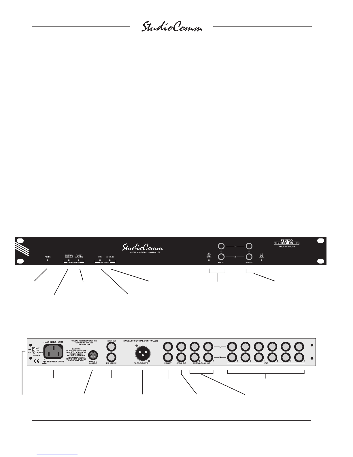
Model 50 Front Panel
Power present
LED
Model 51
Control Console
over current LED
Talent Amplifier
over current LED
Model 50 Back Panel
AC mains
connection
Input data
present LED
Meter output and
Mic Module input
Model 50
input data LED
Dub
output
Stereo line input 7;
LED indicates +4dBu
configuration
Dub output;
LED indicates +4dBu
configuration
Stereo line
inputs 1-6
Mains voltage
configuration
chart
Issue 6, September 2004 Model 50/51 User Guide
Page 8 Studio Technologies, Inc.
To/from Model 51
Control Console
Output to talent
amplifiers
Studio output
Control room
A & B outputs
Page 9

Studio Monitoring
The studio monitoring source is configured to follow either the selected control
room source or the headphone source.
A push button, along with an associated
LED, provides the studio on/off function.
A rotary potentiometer is used to set
the level.
applications a Model 51 will be utilized. In
special applications the Model 50 Central
Controller can be connected directly to a
MIDI bus, allowing the creation of a fully
automated recording or audio routing
system. (For more information on MIDI
support, refer to Appendix A.)
Configuration
Dub Output
A stereo line-level output is provided as
a dub (copy) output. Any of the seven
inputs can be assigned to the dub output.
The dub output can also be configured to
follow the source selected for the control
room output. The slate function allows
communications (voice) audio to be sent
out the dub output. For convenience, the
dub output is available from both the front
and back panels of the Model 50.
Communications Functions
The Model 51 Control Console contains
an internal microphone that is used in
conjunction with the three communications functions. The talk to studio function
interrupts the studio source and sends
communications audio. The talk to phones
function either interrupts the phones
source or adds (sums or mixes) communications audio with the phones source. The
slate function interrupts the dub source
and connects communications audio. The
slate function can be configured to send
a 50Hz sine wave along with communications audio. The audio level of each
communications function is individually
adjustable.
MIDI Control
All Model 50 Central Controller functions
are controlled using system-exclusive MIDI
messages. The Model 51 Control Console “speaks” this language, and in most
The Model 51 Control Console can be
configured to make the system meet a
user’s exact operating environment. As
previously discussed, each of the seven
stereo line inputs can be independently
set for –10dBV or +4dBu operating levels. They also can be set for either mono
or stereo operation. In the mono mode a
signal connected to the left input is sent to
the left and right outputs. The dub output
level can be set for a nominal –10dBV or
+4dBu output level.
Unique to the system is the ability to configure the dim level to one of six values,
ranging from full attenuation to a modest
10dB reduction. The auto dim off function,
when configured, allows any change in
the control room level potentiometer to
automatically turn off an active dim state.
The talk to phones function can be
configured to either interrupt the source
selected for headphone audio and connect communications audio, or to have the
communications audio added (summed
or mixed) with the headphone audio.
The slate function can be configured to
generate a 50Hz sine wave when activated. This provides an audible “marker” for
analog tapes, and a visual indication on
a wave form display screen.
Four functions can be set for push-to-latch
operation if desired: talk to studio, talk to
phones, slate, and control room mono.
Model 50/51 User Guide Issue 6, September 2004
Studio Technologies, Inc. Page 9
Page 10
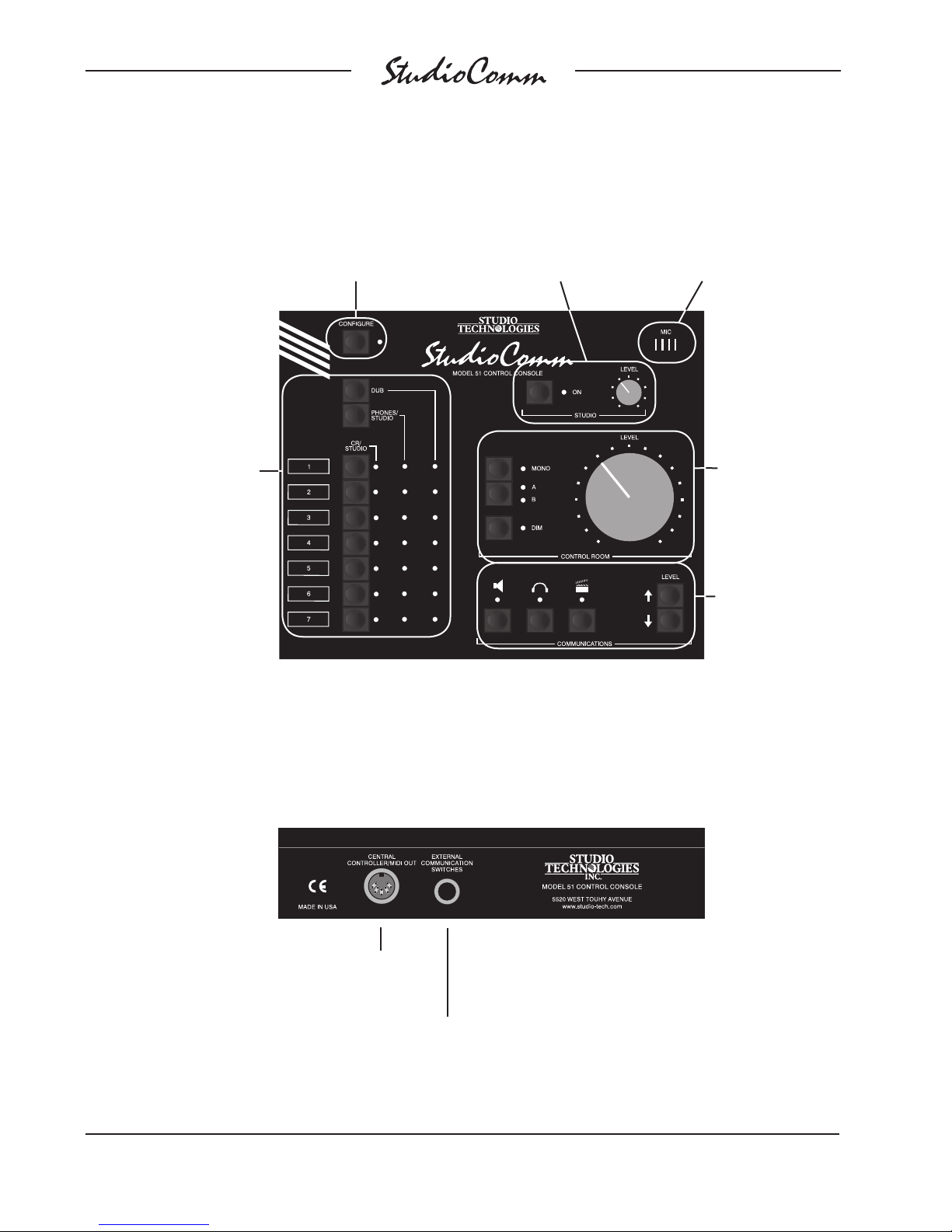
Model 51 Front Panel
Source selection
for control room (CR),
studio, headphones, and
dub; three columns of
LEDs show the currently
selected sources
Configure button
switches between
normal operation
and configure mode
Studio on/off button
and level control
Built-in microphone for
communications
functions (talk to studio,
talk to phones, slate)
Change the control room
level; listen in mono
(L+R); select output A
or B; or reduce the level
by a preset amount
Talk to the studio or
headphones; slate; set
communications levels
Model 51 Back Panel
Issue 6, September 2004 Model 50/51 User Guide
Page 10 Studio Technologies, Inc.
Connection
to the Model 50
Central Controller
Connection for
external talk to studio
and talk to phones
switches
Page 11
The studio output is set to follow the
control room source or the headphone
source. The headphone source is set
for independent selection or to follow
the control room source. The dub source
is set for independent selection or to follow the control room source.
All configuration parameters, along with
“power down” operation conditions, are
stored in nonvolatile memory.
Headphone Monitoring
The StudioComm system contains an
integrated, full-featured headphone (cue)
system. Up to four Model 35 or Model 38
Talent Amplifiers can be connected to
the Model 50’s talent amplifier output.
A single 3-conductor microphone-type
cable carries power and stereo audio.
Using the Model 51 Control Console,
any of the seven stereo inputs can be
assigned to the talent amplifier output.
The talk to phones function allows communications (voice) audio to be sent to
the talent amps. The talent amplifier output is short circuit protected. Error conditions are displayed by the Talent Amplifier
Over Current LED on the Model 50’s front
panel.
Each Model 35 and Model 38 Talent
Amplifier can drive two sets of highimpedance headphones (>150Ω). The
audio output is loud, and very “clean.”
The units feature a built-in level control,
a stereo/mono switch, and a power
present LED.
The Model 38 Talent Amplifier takes the
basics from the Model 35 and adds a
unique stereo preamplifier section. This
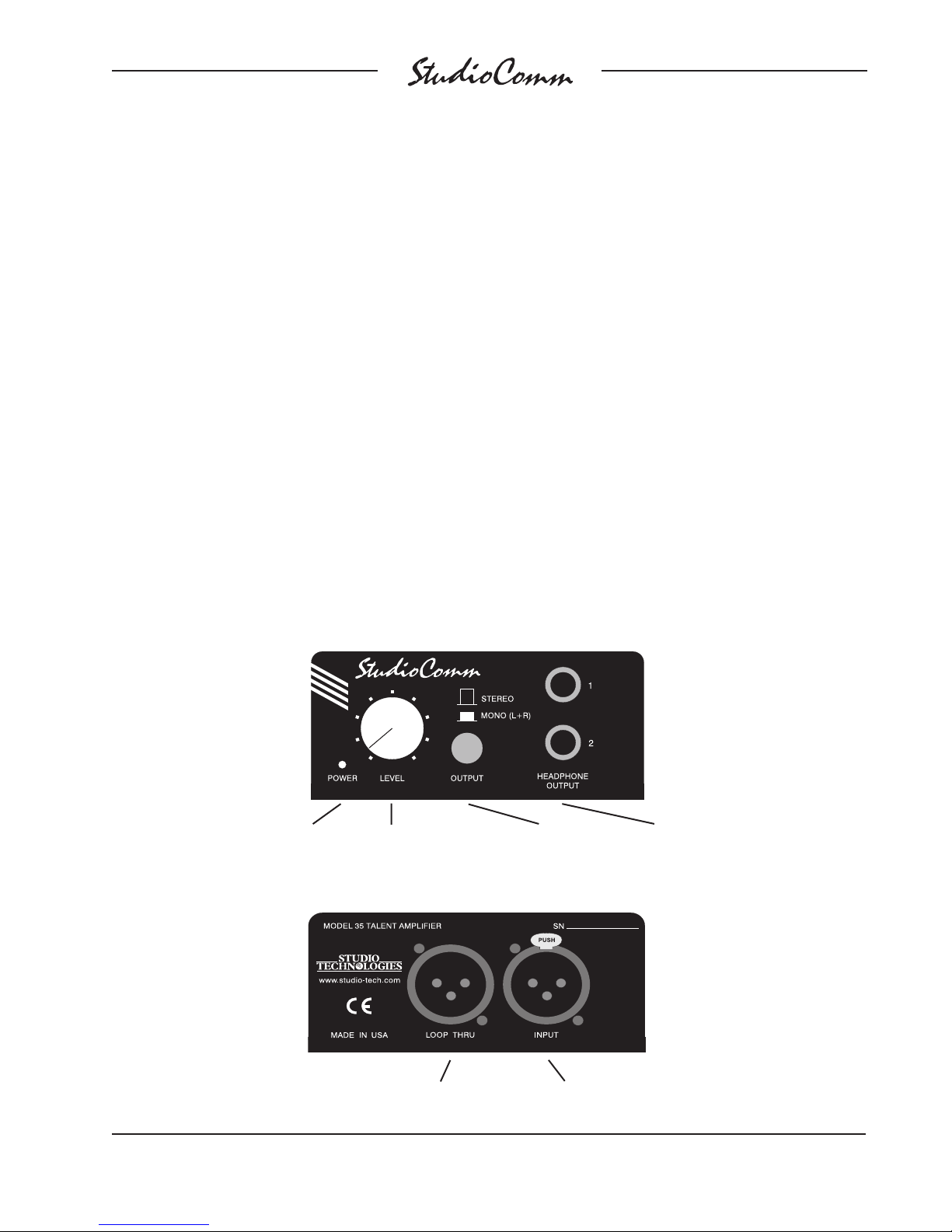
Model 35 Front Panel
Power present
Model 35 Back Panel
LED
Headphone output
level control
Switch between
stereo and mono
(L+R) output
Two headphone
outputs
Model 50/51 User Guide Issue 6, September 2004
Studio Technologies, Inc. Page 11
Connects to additional
talent amplifiers
Connects to the Model 50 or another talent
amplifier’s loop thru connector
Page 12
allows a musician’s microphone or linelevel signal to be “looped” through the
Model 38, boosted by its preamp, and
then combined with the stereo cue mix
supplied by the Model 50. This provides
each Model 38 with an individual headphone mix, solving the classic problem
of wanting “more me” in the phones!
Like the Model 35, the Model 38 is linked
with a Model 50 Central Controller by a
single cable.
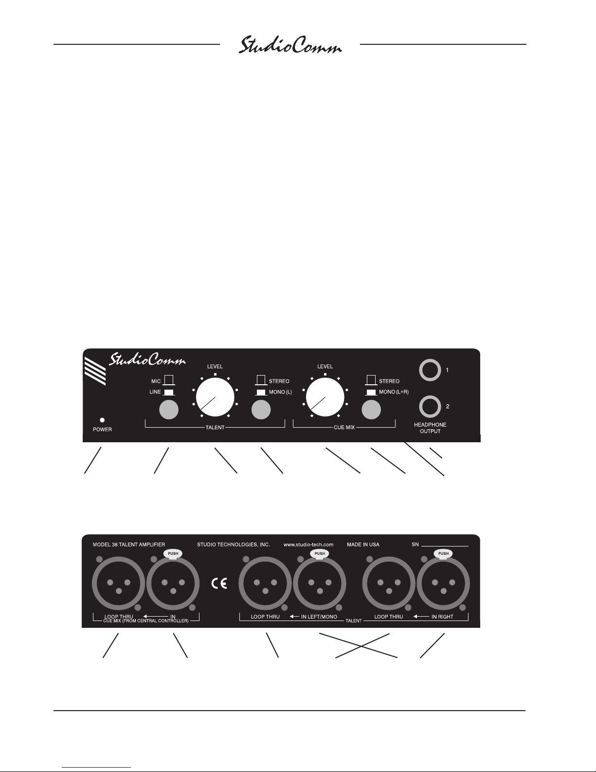
Model 38 Front Panel
Installation
In this section you will be installing the
Model 50 Central Controller in an equipment rack. Audio input and output connections will be made using the Model
50’s multitude of ¼-inch phone jacks.
One or more Model 35 or Model 38 Talent
Amplifiers will be connected. A location
will be selected for the Model 51 Control
Console, and it will be connected to the
Model 50. AC mains power will be connected to the Model 50.
Two headphone outputs
Power present
LED
Mic/Line button switches
the talent input between
microphone and line level
Talent level
to phones
Switch between
stereo and mono
(L only) for the talent
input
Cue mix
level to
phones
Switch between stereo
and mono (L+R) for
the cue mix
Model 38 Back Panel
Connects to additional
talent amplifiers
Issue 6, September 2004 Model 50/51 User Guide
Page 12 Studio Technologies, Inc.
Connects to the
Model 50 or another
talent amplifier’s loop
thru connector
Loop thru connectors parallel the
talent inputs for routing to a digital
audio workstation, effects device,
microphone preamp, etc.
Connects to talent sources
such as keyboards or
microphones
Page 13
System Components
The main StudioComm shipping carton
contains a Model 50 Central Controller,
Model 51 Control Console, 5-conductor
MIDI-style cable, and User Guide. Units
destined for North America are shipped
with an AC mains cord. Your dealer or
distributor will provide an AC mains cord
for non-North American destinations.
Model 35 and Model 38 Talent Amplifiers,
along with accessories, will be contained
in separate cartons. Please check to
ensure you have everything you need.
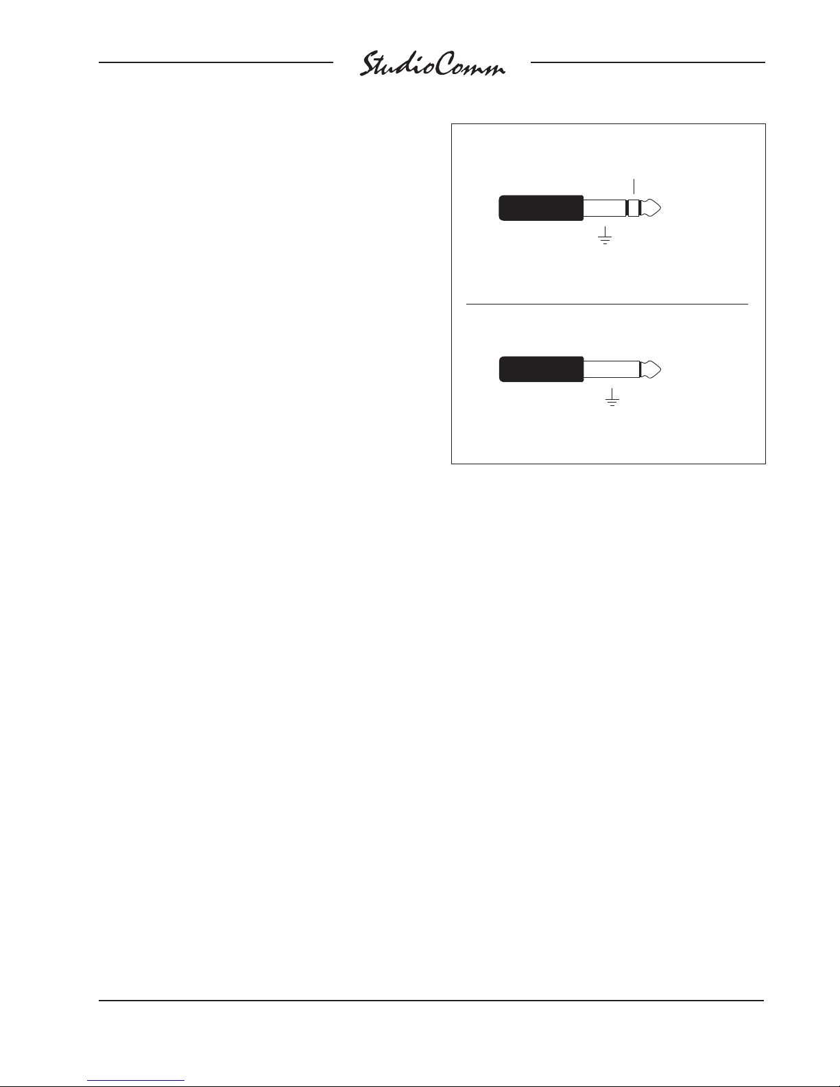
Balanced Input and Output Connections
Ring: –
Tip: +
Sleeve: Shield
(Switchcraft No. 297, Neutrik NP3C, or equivalent)
Unbalanced Input and Output Connections
Tip: +
Mounting the Model 50
The Model 50 requires one space in a
standard 19-inch (48.3cm) equipment
rack. Select a location near where the
Model 51 Control Console will be located.
A cable is provided to connect the Model
50 to the Model 51. If required, you can
supply a longer cable, however 50 feet
(15.3m) is the recommended maximum
length. It is desirable to locate the Model
50 to allow easy access to both the front
and the back panels. The back panel
contains most of the input and output
connectors, while the front panel is used
to access line input 7 and a multiple
(mult) of the dub output. In addition, the
front panel also contains several LED
indicators. The Model 50 is secured to
the equipment rack using two mounting
screws per side.
Audio Inputs and Outputs
The Model 50’s line-level audio input and
output connections are made using
-inch 3-conductor phone jacks. The
¼
choice of phone jacks was simply a
matter of real estate—21 XLR connectors
don’t quite fit on the back of a one rackspace unit!
Sleeve: Shield
(Switchcraft No. 280, Neutrik NP2C, or equivalent)
For connection of balanced input and
output signals, ¼-inch 3-conductor phone
plugs should be used. The plugs should
be wired with tip positive (+ or hot), ring
negative (– or cold), and sleeve shield.
With unbalanced input and output signals,
either ¼-inch 2- or 3-conductor plugs
can be used. With 2-conductor plugs tip
should be wired as positive (+ or hot) and
sleeve as shield. With 3-conductor plugs
tip should be wired as positive (+ or hot)
and both ring and sleeve as shield.
Stereo Line Inputs
The Model 50 provides seven stereo
line-level inputs. Inputs 1 through 6 are
located on the back panel; input 7 is on
the front. Each input is electronically balanced, and can be configured for compatibility with –10dBV or +4dBu signal levels.
The Model 51 Control Console gives you
push-button control, so you can easily
change input sensitivities at any time
(refer to the Configuration section under Input Sensitivity). Monaural sources
Model 50/51 User Guide Issue 6, September 2004
Studio Technologies, Inc. Page 13
Page 14

should be connected to the left (L) input
and configured for mono operation (refer
to the Configuration section under Stereo/
Mono Input).
Control Room Outputs
The Model 50 contains two stereo linelevel outputs for connection to two audio
power amplifiers. These audio amps
serve two pairs of loudspeakers that are
located in the control room. (Of course
the control room outputs can be connected to loudspeakers that contain integral
power amplifiers, such as the products
from Genelec.)
Dub Output
The Model 50 contains a stereo line-level
output which is intended for connection
to a variety of analog audio devices. The
dub output is electronically balanced
and capable of driving 600 ohm loads or
greater. With the input impedance of most
audio devices at 10k ohms or greater, the
dub output can easily drive 10 or more
devices simultaneously. The dub output
can be configured for a nominal level of
–10dBV or +4dBu, so you can connect
to all line-level inputs with no hassle (refer
to the Configuration section under Dub
Output Level).
The outputs, labeled A and B, are
electronically balanced and capable
of driving loads of 600 ohms or greater.
In most situations best performance will
be obtained if the audio amplifier’s input
sensitivity is set to near maximum. Refer
to the Technical Notes section for details
on setting amplifier sensitivity.
Studio Output
The Model 50 contains a stereo line-level
output for connection to an audio power
amplifier. This audio amplifier serves the
pair of loudspeakers that is located in the
studio area. (Of course the studio output
can be connected to loudspeakers that
contain integral power amplifiers.)
The output is electronically balanced
and capable of driving loads of 600
ohms or greater. In most situations best
performance will be obtained if the audio
amplifier’s input sensitivity is set to near
maximum. Refer to the Technical Notes
section for details on setting amplifier
sensitivity.
The dub output is available on phone
jacks located on both the front and back
panels of the Model 50. The phone jacks
are connected in parallel, being a multiple
or mult of each other; one set of dub
output circuits drive both outputs. The
design intention was that permanent
connections would be made to the back
panel dub output, while the front panel
dub output would remain available for
“on the spot” use.
Meter Output
The meter output is intended for connection to VU- or PPM-style meters or meter
panels that contains input buffer circuitry
or series current-limiting resistors. The meter output channels have a nominal level
of +4dBu, but are not precisely calibrated
by Model 50 circuitry. While 1%-tolerance
resistors are used in the Model 50, the
meters or meter panels should include
calibration trim pots to ensure the most
accurate level reading.
A single ¼-inch 3-conductor jack is used
to connect to the stereo meter output.
Each output channel is unbalanced, has
Issue 6, September 2004 Model 50/51 User Guide
Page 14 Studio Technologies, Inc.
Page 15
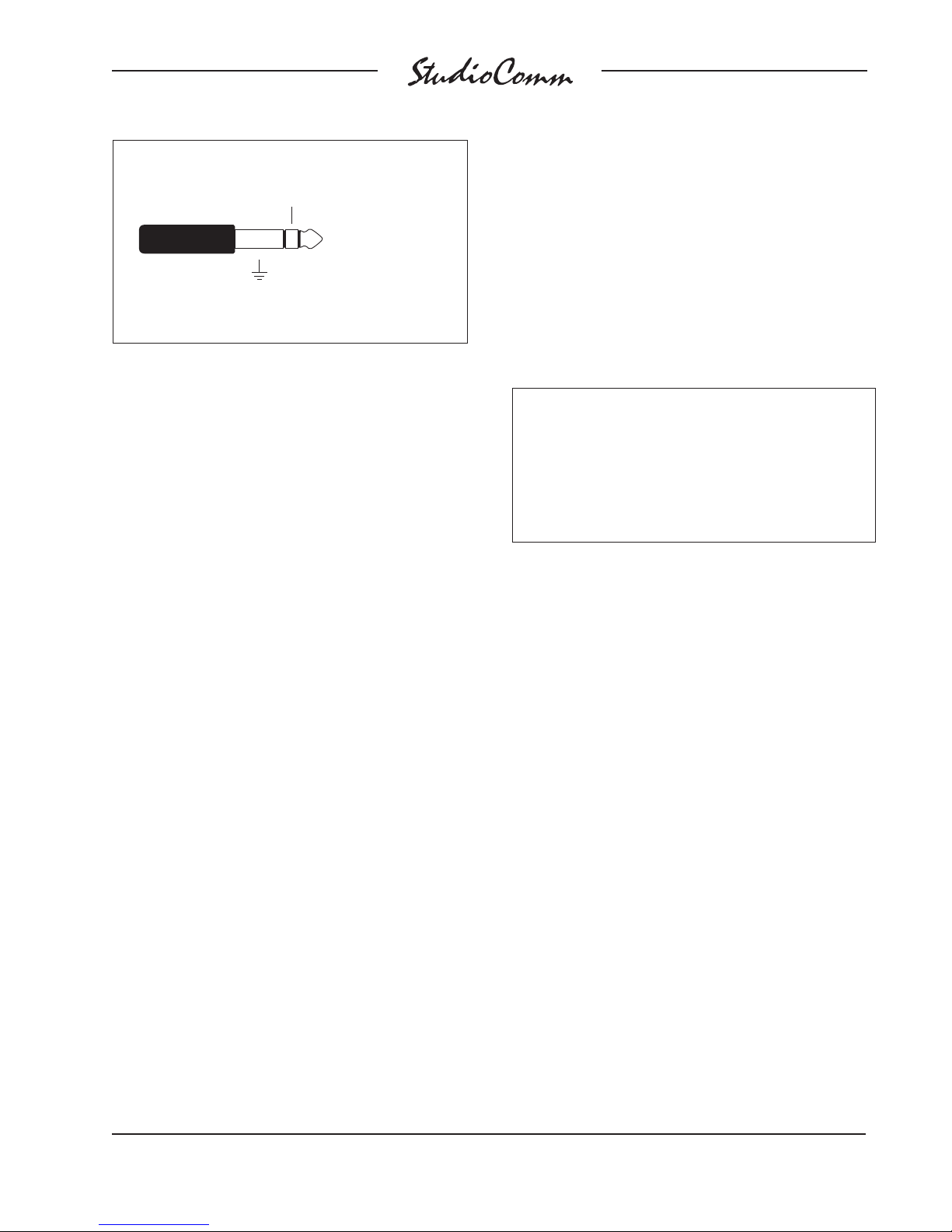
Meter Output
Ring: Right output
Tip: Left output
Sleeve: Common
(Switchcraft No. 297, Neutrik NP3C, or equivalent)
a nominal level of +4dBu, and is capable
of driving loads of 2k ohms and greater. A
¼-inch 3-conductor plug should be wired
with tip for the left output, ring for the right
output, and sleeve for common.
Mic Module Input
A ¼
-inch 3-conductor phone jack, labeled
Mic Module, is located on the back panel.
In most cases the Mic Module input will
not be used, and no plug should be inserted. For details on using the Mic Module
input, refer to the Advanced Installation
Topics section later in this guide.
Talent Amplifier Output
Up to four Model 35 or Model 38 Talent
Amplifiers can be connected in any combination to the Model 50’s talent amplifier
output. The output connector is a 3-pin
male XLR-type. For best performance, use
low-capacitance shielded microphonetype cable to distribute the talent amplifier
signal. If you have a choice, select cables
with the heaviest wire gauge commonly
available. This will reduce voltage drop
when using long cable runs. Refer to the
Technical Notes section for additional
information.
The simplest installation would use a
microphone cable to connect the Model
50 to the first talent amplifier; the loop
through connector on that talent amp sending the signal on to the next talent amp.
For convenience, you may want to wire
your facility to allow easy access to the
talent amplifier signal at all locations where
talent amplifiers might be used. The talent amplifiers connect to the Model 50 in
parallel, so the connectors on the distribution panels or mult boxes must be wired in
parallel.
Warning: Do not connect the Model 50’s
talent amplifier output to anything but
Studio Technologies’ talent amplifiers.
Some audio equipment may be damaged by the +23Vdc contained on pin 2
of the talent amplifier output connector.
Several mounting options are available for
the Model 35 and 38 Talent Amplifiers. For
details refer to the Mounting Options sections in the Advanced Installation Topics
section of this user guide.
In special cases you may need to obtain
a stereo, balanced line level output signal
from the Model 50 talent amplifier output.
The Model 70 Interface is available for this
purpose. For details refer to the Advanced
Installation Topics section later in this guide.
Locating the Model 51 Control Console
The Model 51 was designed for desktop
use, however provision has also been
made for microphone-stand mounting.
For details refer to Mounting Options in
this section.
Connecting the Model 50 to the Model 51
A standard 5-conductor MIDI-style cable
is used to connect the Model 50 to the
Model 51; a cable is included with your
system. Just connect the cable between
Model 50/51 User Guide Issue 6, September 2004
Studio Technologies, Inc. Page 15
Page 16
the female 5-pin DIN-type connectors
on the back of the Model 50 and 51,
and you’re done.
Note: If you require a longer cable, be
certain to buy a MIDI cable that has all five
pins wired. If they aren’t all connected, the
Model 51 will not operate. This is because
the Model 50 powers the Model 51 with
the pins that aren’t used for MIDI data.
For best performance, the cable that
connects the Model 50 with the Model
51 should be limited to 50 feet (15.3m).
Should you need to exceed this length,
refer to the Technical Notes section
of this guide for details on the cable
requirements.
For more information on MIDI, and using
controllers other than the Model 51,
please refer to Appendix A.
Remote Control Inputs
The Model 51 allows the connection of
two external switches or contact closures.
Refer to the Advanced Installation Topics
section of this guide for details.
Should it be necessary to change
the unit’s operating voltage it must be
performed only at the factory or by
an authorized service technician.
The Model 50 uses an IEC standard
connector to mate with the AC mains
cord. The wire colors in the AC mains
cord should conform to the internationally
recognized CEE color code and must
be wired accordingly:
Connection Wire Color
Neutral (N) Light Blue
Line (L) Brown
Protective Earth (E) Green/Yellow
Safety Warning: The Model 50 does
not contain an AC mains disconnect
switch. As such the mains cord plug
serves as the disconnection device.
Safety consideration requires that
the plug and associated outlet be
easily accessible to allow rapid disconnection of mains power should it prove
necessary.
AC Mains Power
The Model 50 is internally configured to
operate from either 100, 120, or 220/240V,
50/60Hz. In most cases, units shipped
to North America are factory selected for
120V operation. Units bound for Japan are
selected for 100V, while our friends “down
under” and in Europe receive units set for
220/240V. Before connecting the Model
50 to mains power, check that it is configured to match the local mains voltage.
Look on the back panel, adjacent to the
power entry connector, for the configured
voltage(s). Note than an incorrect configu-
As soon as mains power is applied, the
Model 50’s power present LED will light.
The Model 51 will go through its powerup sequence lighting each LED in a rapid
sequence. The power present LEDs on
the talent amplifiers will also light.
The two Over Current LEDs located on
the front panel of the Model 50 should not
be lit. If either or both are flashing, immediately refer to the Troubleshooting section
of this guide. If everything appears to be
functioning properly you are now ready to
configure the system.
ration could seriously damage the unit.
Issue 6, September 2004 Model 50/51 User Guide
Page 16 Studio Technologies, Inc.
Page 17
Advanced
Installation Topics
Model 35 Stand Mounting
Included with each Model 35 Talent
Amplifier is a nifty mounting adapter that
allows the unit to be conveniently attached
to a microphone stand. Please refer to the
Installation Guide provided in the Model
35’s shipping carton for details.
Model 38 and Model 51 Mounting
Options
The design of the Model 51 did not allow
the inclusion of threaded inserts, so holes
¼
of adequate size to allow
-20 round head
machine screws are provided. It is intend-
5
/
ed that screws of
-inch length, along
8
with lock washers and machine nuts, will
securely attach a 25 Series mounting
clamp assembly. The cover of the Model
51 will have to be removed to gain access to mounting holes. Be careful when
selecting the mounting screws—exceeding the recommended
5
/
-inch length will
8
cause the mounting screws to damage the
Model 51’s internal components.
The Model 38 Talent Amplifier and the
Model 51 Control Console include provisions for mounting to microphone stands,
equipment consoles, etc. To avoid
“reinventing the wheel,” our products are
compatible with the 25 Series components
from OmniMount Systems, a supplier of
finely engineered mounting systems. This
firm makes many versions of the 25 Series;
one of which should fit your needs. If you
desire microphone stand mounting the following components would be appro-priate
for English-thread applications: 25RST-25H
Straight Tube Reverse Mount with Quick
Release, along with a 25MA Microphone
Stand Adapter. (If quick adjustment is not
required the 25RST Straight Tube Reverse
Mount can be used in place of the first
item.) When connecting to metric-thread
stands please contact OmniMount
for the correct part numbers.
The bottom surface of the Model 38 Talent
Amplifier contains two threaded inserts
that will accept English-standard ¼ -20
screws. Using two,
5
/
-inch long, round-
8
head machine screws, the 25 Series clamp
assembly can be directly attached. The
cover of the Model 38 does not have to
be removed.
Remote Control Inputs
The Model 51 allows you to connect two
external switches or contact closures to
enable system functions. Input 1 allows
either a remote talk to studio or a remote
control room source select function to be
implemented. Input 2 allows a remote talk
to phones function to be implemented.
Using the remote “talk to” functions, it may
be useful to install switches at a producer
or director location. The Model 51 continues to provide local talk to studio and
talk to phones access even when external
switches are connected.
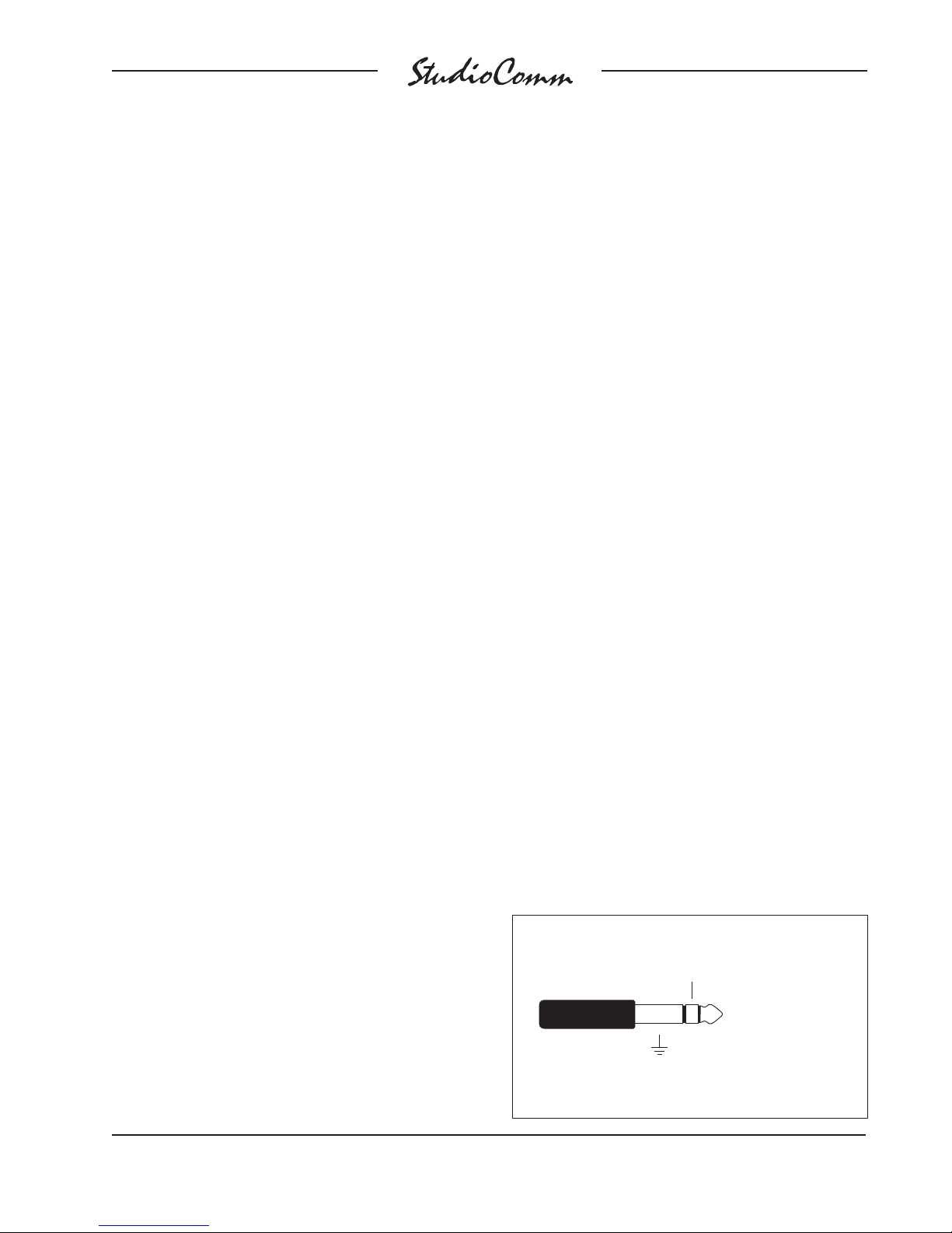
The required connector is a ¼ -inch
3-conductor phone plug. Tip is talk to
studio or control room source select, ring
is talk to phones, and sleeve is common.
External Communications Switches
Ring: Talk to phones
Tip: Talk to studio
Sleeve: Ground
(Switchcraft No. 297, Neutrik NP3C, or equivalent)
Model 50/51 User Guide Issue 6, September 2004
Studio Technologies, Inc. Page 17
Page 18
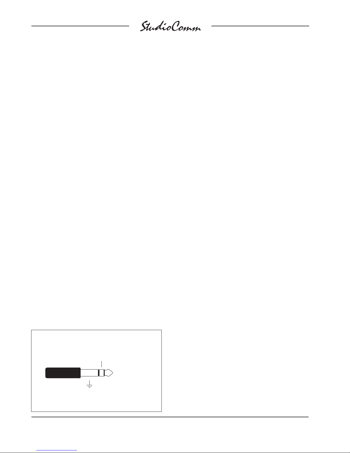
Switchcraft No. 297, Neutrik NP3C, or
equivalent will work correctly. Use a momentary, single-pole, single-throw switch
for each remote function. The respective
function is activated when the tip or ring
get shorted to the sleeve.
While the Model 51’s talk to studio and
talk to phones buttons can be configured
to latch, the remote control inputs are
always push to activate. This is provided
as a safety feature preventing an external
user from “latching” one of the functions
to the on state.
Mic Module Input
The Model 51 Control Console contains
a microphone which provides the audio
source for the Model 50’s communications functions. In special applications the
Model 51 may not be used, and a separate source of communications audio will
be necessary. The Mic Module input on
the back panel of the Model 50 allows this
to be easily accomplished.
Even if you are using the Model 51 Control Console you may want to provide an
alternate source of communications audio.
To use your own microphone and preamp,
directly connect it using the Mic Module
input jack. The Mic Module input is a
-inch 3-conductor phone jack with
¼
+12Vdc on tip, audio input on ring, and
Mic Module Input
Ring: Communications
Audio Input
Tip: +12Vdc
Sleeve: Ground
ground on sleeve. The audio input requires a nominal –10dBu signal (–10dBu,
not –10dBV!). The +12Vdc on the tip is
from the same source that powers the
Model 51, and is provided to power an
external preamp. If you feel the urge to
use this power source, be aware that it
only provides 110 milliamps of current of
which the Model 51 needs about 100mA.
So go ahead and use all the current you
need, as long as it doesn’t exceed 10mA!
Note: Communications audio from the
Model 51 is routed into the Model 50’s
circuitry through the normal connection
on the ring contact of the Mic Module
input jack. When a phone plug is inserted
into the Mic Module input, the audio path
from the Model 51 to the Model 50 is broken. This means you can’t use the Model
51’s microphone and the Mic Module
input at the same time.
Model 70 Interface
In most cases Model 35 and/or Model 38
Talents Amplifiers will be used to drive
headphones associated with a StudioComm installation. In special cases a line
level signal may be required to interface
the Model 50 Central Controller’s talent
amplifier output with other audio equipment. An example would be to use the
Model 50 with an existing headphone
system. The Model 70 Interface is used
to convert the talent amplifier signal to
a stereo, balanced line level signal.
Installation is very simple. Connect the
Model 70 to the Model 50 Central Controller’s talent amplifier output using a
standard 3-conductor microphone-type
cable. For best performance, use lowcapacitance shielded cable.
(Switchcraft No. 297, Neutrik NP3C, or equivalent)
Issue 6, September 2004 Model 50/51 User Guide
Page 18 Studio Technologies, Inc.
Page 19
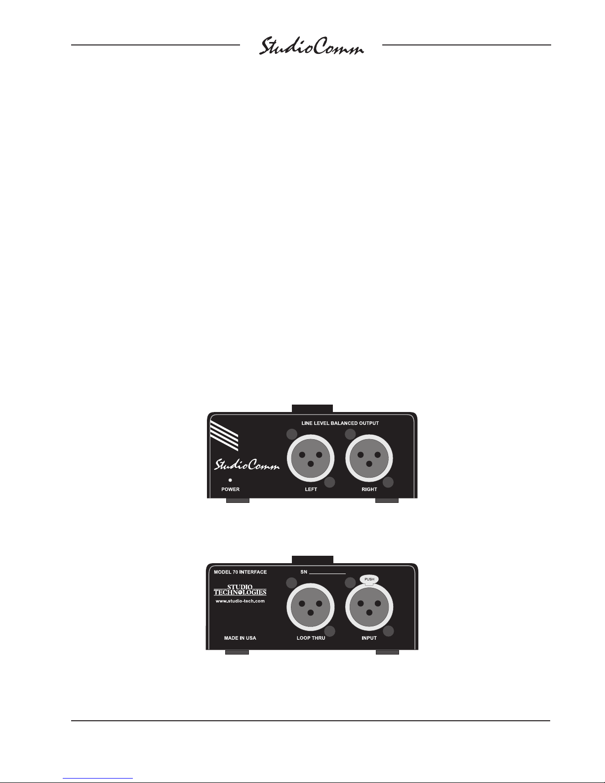
The Model 70 provides independent
left and right balanced outputs. Pin 1 is
shield, pin 2 is signal positive (+ or hot),
and pin 3 is signal negative (– or cold).
The electronically balanced outputs
have a nominal signal level of +4dBu
and are capable of driving loads of 600
ohms or greater.
The Model 70 can be used by itself, or
in conjunction with up to four Model 35
or Model 38 Talent Amplifiers. The loop
through connector on the Model 70 can
be used to connect to a Model 35 or 38
Talent Amplifier.
Configuration
Many StudioComm functions can be configured to meet the exact needs of your
installation. Here’s an overview of what
you can configure:
• –10dBV or +4dBu level for each input
• Stereo or mono for each input
• –10dBV or +4dBu level for the dub
output
• Dim level
• Auto dim off function
• Studio source follows control room or
headphone source
Model 70 Front Panel
Model 70 Back Panel
Model 50/51 User Guide Issue 6, September 2004
Studio Technologies, Inc. Page 19
Page 20

• Headphone source is independently
selected or follows control room source
• Momentary or latching operation for
mono, talk to studio, talk to phones,
and slate buttons
• Talk to phones interrupts or adds to
phones source
• 50Hz slate tone on or off
• Dub source is independently selected
or follows control room source
For convenience, Input 7 is located on
the front panel of the Model 50. It has
a green LED beside it labeled +4 Input
Level. When lit, it tells you that Input 7 is
set for +4dBu. This means each time you
connect a new signal to Input 7, you don’t
have to go into the configure mode to
determine the input sensitivity. You should
note, however, that configure settings
aren’t updated until you leave the configure mode, so the +4 Input Level LED
won’t reflect a change until you exit.
• Remote control room source select
parameters
• Level control auto mute
The Configure button allows the Model 51
to go into the configure mode. While in the
configure mode, all the Model 51’s buttons
and LEDs are associated with configure
functions. Refer to the Model 51 Configuration Chart later in this section.
To enter the configure mode, press and
hold the Configure button for two seconds.
While in the configure mode, all audio outputs switch off and the orange LED beside
the Configure button will flash. As you make
changes, the Model 51 keeps track of the
new settings and updates the system when
you exit the configure mode. You must exit
the configure mode before any changes
take effect.
Input Sensitivity
The CR/Studio column of seven red LEDs
shows you whether an input is set to be
compatible with –10dBV or +4dBu signal
levels. When a red LED in the CR/Studio
column is off, it means the input is set to
–10dBV. When lit, the corresponding input
is set to +4dBu. Just press the CR/Studio
buttons to toggle inputs 1 through 7
between –10dBV and +4dBu.
Stereo/Mono Input
The Phones/Studio column of seven green
LEDs indicates whether an input is configured for mono or stereo operation. When
an LED in this column is off, the input is
set for stereo; the LED on means the corresponding input is set for mono. In mono
mode, the left input is sent out both the
left and right outputs. To toggle a channel
between stereo and mono, press and hold
the Phones/Studio button and press the
CR/Studio buttons that correspond to inputs 1 through 7. After you leave the configure mode, inputs configured for a mono
source will flash during normal operation.
Dub Output Level
The Dub column of orange LEDs will help
you configure two options: dub output
level and dim level. The orange LED in
the first row (number 1 at the top) tells you
whether the dub output is set to –10dBV
or +4dBu. When the LED is off, the dub
output is set to –10dBV; when it’s on, the
dub output is configured for +4dBu. The
dub output on the front panel is in parallel
with the dub output on the back panel, so
one configure setting controls both. For
convenience, a green LED on the front
panel is provided that lights when the dub
output level is set to +4dBu. This means
Issue 6, September 2004 Model 50/51 User Guide
Page 20 Studio Technologies, Inc.
Page 21

you don’t have to use the configure mode
to determine the dub output level. And
just like the +4 Input Level LED for Input
7, the +4 Dub Level LED does not reflect a
change until you exit the configure mode.
Dim Level
The dim function is used to reduce the
control room output level a preset amount
whenever you press the Dim button. You
can take a quick phone call without using the level control to change the control
room level. Also, any time you press the
talk to studio, talk to phones, or slate buttons the dim function is activated.
In the configure mode, LEDs 2 through 7
in the Dub column indicate the selected
dim level. Dim can only have a single setting, so only one of the orange LEDs
is on at a time.
Row Number Dim Value (dB)
2 Max. attenuation
(approx. 72dB)
3 30
4 25
5 20
6 15
7 10
When the orange LED is on in row two,
dim will cause an approximately full mute
(no output). Dim is down 30dB in row
three, 25dB in row four, and so forth. To
change the dim level, hold down the Dub
button while pressing the CR/Studio button of your choice.
Studio Source Selection
For space considerations, a separate
push button and column of LEDs is not
provided for studio source selection.
The Model 51 is configured for either the
studio source to follow the control room
source, or the studio source to follow the
headphone source.
In configure mode, the red Studio On LED
tells you which function the studio source
will follow. When the LED is off, the studio
will follow the control room source; when
it’s on, the studio will follow the headphone
source. Press the Studio On button to
toggle the setting.
Mono Function
The Mono function allows the control room
output to be placed in the mono (L+R)
mode. When you’re in configure mode,
the red LED labeled Mono tells you whether the Mono button works as a momentary
or latching button. When the button is set
to momentary, the LED will be off and
mono mode will only be active while you
press and hold the Mono button. When
the LED is on, the button is set to latch.
With this setting, you can press the Mono
button once and it will remain in mono
mode until you press it again.
Auto Dim Off
The auto dim off function is unique to
StudioComm products, making the dim
function respond to real world operating
conditions. When enabled, the function
automatically turns the dim function off if
a change is made to the control room level
potentiometer while the unit is already in
dim mode. This prevents a heart-stopping
blast of audio when an engineer presses
the dim button to turn dim on, but actually
turns it off because the unit was already
in the dim mode. While it’s hard to explain
unless you’ve used a console and experienced this in person, trust us, this situation
does happen! Auto dim off is a wonderful
“real-world” function and in most cases
should be configured.
Model 50/51 User Guide Issue 6, September 2004
Studio Technologies, Inc. Page 21
Page 22
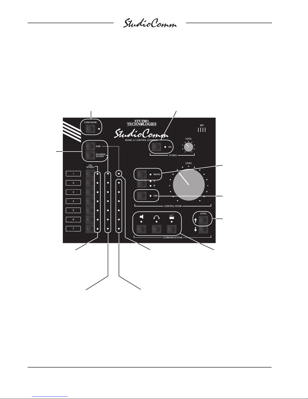
Model 51 Configuration Chart—Main Functions
Press
and hold
Dub and
Phone/Studio
for 2 seconds
to reset all
parameters
to factory
defaults
Press and hold
Configure for two seconds
to enter or exit the configure
mode; while in configure,
LED will flash
Press button to toggle between
studio follows control room
source and studio follows head-
phone source; LED on means
studio follows headphones
Press Mono to toggle
between latching or
momentary operation;
LED on means the
Mono button is set
to latch
Press Dim to toggle
the automatic dim off
function; LED on means
auto dim off function
is active
Press and hold Level
Up to activate alternate
configure functions
(refer to next page)
Press CR/Studio 1 through
7 to toggle each channel’s
input sensitivity between
–10dBV and +4dBu; LED on
means input is set to +4dBu
Press and hold Phones/Studio,
then press CR/Studio 1 through 7
to toggle the inputs between stereo
and mono operation; LED on
means input is set to mono
Issue 6, September 2004 Model 50/51 User Guide
Page 22 Studio Technologies, Inc.
Press and hold Dub,
then press CR/Studio 1
to toggle the dub output
between –10dBV and
+4dBu; LED on means
dub is set to +4dBu
Press and hold Dub, then press
CR/Studio 2 through 7 to select a dim level:
LED 2 is Max. attenuation (approx. 72dB)
LED 3 is 30dB
LED 4 is 25dB
LED 5 is 20dB
LED 6 is 15dB
LED 7 is 10dB
Press a Communications
button to toggle between
latching or momentary
operation; LED on means
the button is set to latch
Page 23
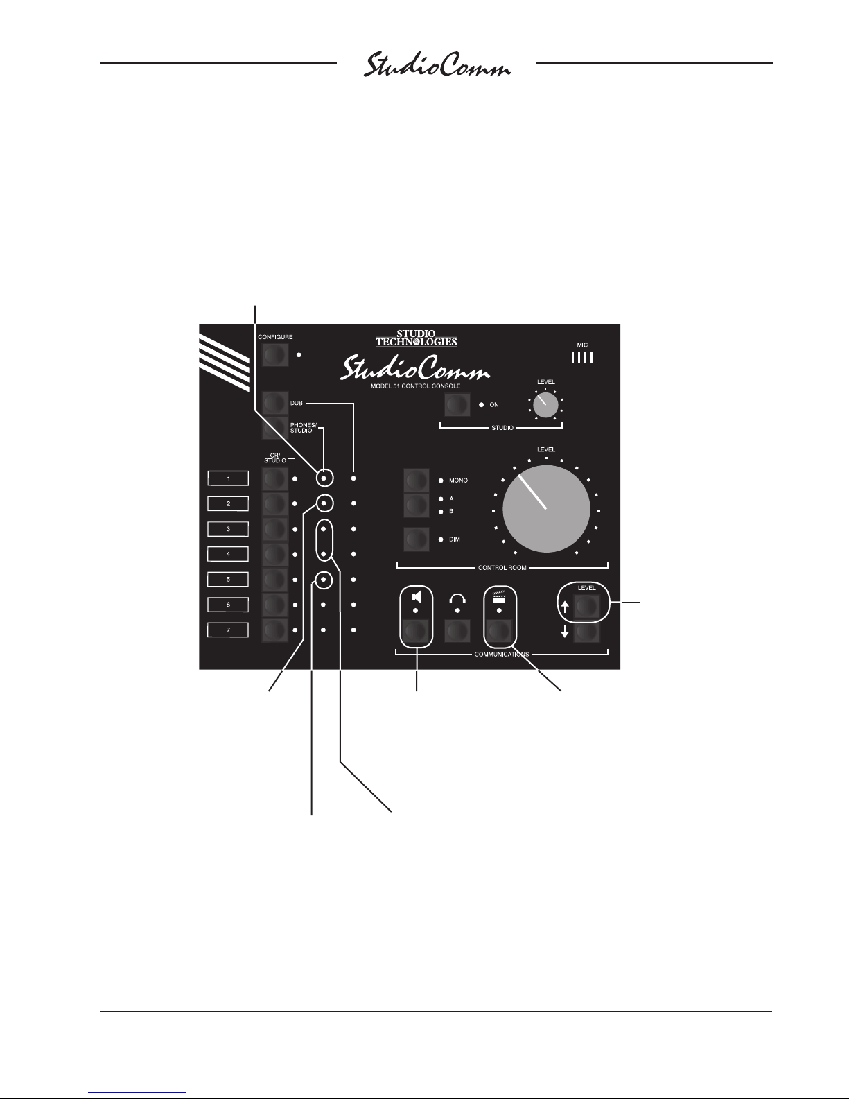
Model 51 Configuration Chart—Alternate Functions
Press and hold Phones/Studio, then press
CR/Studio 1 to toggle between normal
headphone source and headphones follow
control room source; LED on means head-
phones follow control room
Press and hold Phones/Studio,
then press CR/Studio 2 to toggle
between normal dub source and
dub follows control room source;
LED on means dub follows
control room
Press and hold Phones/Studio,
then press CR/Studio 5 to toggle the
state of the level control auto mute
function; when the LED is lit the
function is enabled
Press Talk to Studio to
toggle phones interrupt
and phones add; LED
on means talk to
phones is add
Press and hold Phones/Studio,
then press CR/Studio 3 to configure
remote control room source select;
LED on means function enabled
Press and hold Phones/Studio,
then press CR/Studio 4 to configure
channel associated with remote
control room source select;
LED off means channel 6 selected;
LED on means channel 7
Press Slate to toggle to
50Hz slate tone; LED on
means 50Hz tone is on
Press and hold Level
Up to activate alternate
configure functions
Model 50/51 User Guide Issue 6, September 2004
Studio Technologies, Inc. Page 23
Page 24

In the configure mode the Dim LED tells
you if auto dim off is enabled. When the
dim LED is off, the auto dim off function is
off; when the Dim LED is lit, the auto dim off
function is on.
Communications Functions
There are three Communications buttons at
the bottom center of the Model 51. Moving
from left to right, the buttons are talk to studio, talk to headphones, and slate. During
configuration, LEDs above the Communications buttons tell you whether the buttons
will latch when you press them. When an
LED is off, the button below it won’t latch.
You would have to press and hold the button to activate the function. When an LED
is on, it indicates that the button will latch.
Pressing the button will activate the function
until it’s pressed again.
Talk to Phones Interrupt or Add
The talk to phones function can be configured to either interrupt the source selected
for phones audio and connect communications audio, or to have the communications audio added (summed or mixed)
with the phones audio.
While holding Level Up, the talk to studio
LED is used to display whether talk to
phones will interrupt the phones source,
or add to the phones source. When the
LED is off, the selected phones source
will be interrupted and the communications audio source will be connected;
when the LED is on the communications
audio source will be added (mixed) with
the phones audio source. While holding
Level Up, press the button below the
LED to toggle the setting.
Note that the Model 51’s external communications switch inputs are always configured
for momentary operation. They cannot be
set for push-to-latch operation.
Reset Factory Defaults
Provision has been made to allow you to
return all configurable parameters to the
factory default values. With the Model 51
in the configure mode, press and hold both
the Dub and Phones/Studio buttons. After
two seconds the factory defaults will be
stored in memory, the configure mode will
automatically end, and the Model 51 will
return to normal operation.
Alternate Configure Functions
To allow additional functions to be configured, an alternate configure mode is utilized. By pressing and holding the
Level Up button the alternate functions
are accessed. This is like the ALT key
on your personal-computer keyboard.
50Hz Slate Tone
A 50Hz slate tone can be generated
whenever slate is active. While holding
Level Up, the Slate LED is used to display
whether the 50Hz tone is selected. When
the LED is off, the 50Hz slate tone is off;
when the LED is on, the slate tone is
active whenever slate is active. While
holding Level Up, press the button
below the LED to toggle the setting.
Headphone Source Selection
The default configuration makes the
selection of the headphone source independent of the control room or dub selections. While this is most flexible there are
operating scenarios where it would be
convenient for the headphone source to
follow whatever is selected for the control
room source.
While holding Level Up, the first (top) LED
associated with the Phones/Studio column
Issue 6, September 2004 Model 50/51 User Guide
Page 24 Studio Technologies, Inc.
Page 25

of LEDs displays the headphone source
mode. When the LED is off the headphone
source is selected independently of the
control room source. When the LED is
lit the headphone source follows the
control room source. To make a change
you hold Level Up, hold the Phones/Studio button and press the input 1 button. If
you can make this change using only one
hand, pat yourself on the back with the
other one!
Level Control Auto Mute
The level control auto mute function
automatically mutes the monitor output
channels whenever the rotary level control knob is in its fully counterclockwise
position. In some applications it may be
desirable to enable this function. When
disabled, the rotary level control adjusts
the monitor output level over an approximately 72dB range; no automatic muting
takes place.
Dub Source Selection
The default configuration makes the selection of the dub source independent of the
control room or headphone selections.
While this most flexible there are operational scenarios where it would be convenient for the dub source to follow whatever
is selected for the control room source.
While holding Level Up, the second LED
associated with the Phones/Studio column of LEDs displays the dub source
mode. When the LED is off the dub source
is selected independently of the control
room source. When the LED is lit the dub
source follows the control room source. To
make a change you hold Level Up, hold
the Phones/Studio button and press the
CR/Studio button 2.
Remote Control Room Source Select
The Remote Control Room Source Select
function allows a contact closure to automatically select input 6 or 7 as the control
room source. The remote control input
connection that is, by default, associated
with the remote talk to studio function is
used to activate Remote Control Room
Source Select.
While holding Level Up, the third and four
LEDs associated with the Phones/Studio
column of LEDs display the status of the
Remote Control Room Source Select function. When the third LED is off the function
is not active. When the third LED is on the
function is active. The fourth LED displays
the input channel associated with the
function. When the LED is off channel 6
is selected. When the LED is on channel 7
is selected.
Operation
Now that you’ve installed and configured the system, you’re ready to go. You
should find operation very easy.
Model 50 Central Controller
The Model 50 front panel contains seven
LEDs, one stereo line input, and one stereo line output.
The power present LED should be lit
whenever AC mains power is connected.
During normal operation the two Over
Current LEDs will not be lit. They will flash
only if there is a problem interfacing with
the Model 51 Control Console or the talent
amplifiers that you have connected. Refer
to Troubleshooting section if either Over
Current LED lights.
Model 50/51 User Guide Issue 6, September 2004
Studio Technologies, Inc. Page 25
Page 26

When used with the Model 51 Control Console, both Input Data LEDs will light whenever a message is received. Why are there
two LEDs? They are provided for diagnostic
use in those special cases where the Model
51 is not used, and another source is providing the messages. The Bus LED lights
whenever any data is received, whether the
messages are intended for the Model 50 or
not. The Model 50 Input Data LED will light
only when a MIDI-exclusive message that
matches the Model 50’s format is received.
Refer to the Troubleshooting section if neither LED flashes during operation with the
Model 51 Control Console.
Input 7 is located on the front panel for easy
access; connecting a temporary source to
your system doesn’t require getting at the
back of the Model 50. The LED associated
with input 7 will light whenever the input
is configured for +4dBu operation. If you
require a change in input level refer to the
Configuration section for details.
Again as a convenience function, dub output is available on the front panel. The LED
associated with the dub output is lit whenever the output is set for +4dBu operation.
Refer to the Configuration section if you
require a change in dub configuration.
Model 51 Control Console
All StudioComm functions are controlled
using the Model 51 Control Console. To
make things easy, we’ve divided the
StudioComm functions into four main
groups: input-output selection, control
room outputs, studio output, and communications functions.
Input-Output Selection
Input-output selection is simple. To select
an input for monitoring in the control room,
press one of the seven CR/Studio buttons.
The corresponding LED in the CR/Studio
column will light to let you know which input is selected. If the input is set for mono
the LED will continually flash on and off as
a warning.
If the remote control room source select
function is enabled, the select button
associated with either input 6 or input 7
will not be usable. A remote signal will
cause this input to be selected. Whenever
the remote signal is activated, the control
room source will automatically change to
the designated input (6 or 7). When the
remote signal is no longer active, the control room input source will return to
the previous selection.
The source selected for control room
monitoring will automatically be connected to the meter output. There is no independent selection of the meter output.
If the studio source is configured to follow
the control room source, it will automatically switch to the input you select. You
can easily tell if the studio is following
the control room because whenever the
studio output is on, the studio On LED will
flash each time you select a new input.
Selection of the headphone source depends on how the Model 51 has been
configured. In the default operating mode,
to select an input for the headphones,
press and hold the Phones/Studio button
and press one of the seven CR/Studio
buttons. In the Phones/Studio column,
the LED for the input you select will light.
If the input is set for mono the LED will
continually flash on and off as a warning.
If the studio source is configured to follow
the headphone source, the studio source
will automatically switch to the same input,
and, whenever the studio output is on, the
studio On LED will flash once.
Issue 6, September 2004 Model 50/51 User Guide
Page 26 Studio Technologies, Inc.
Page 27

If the headphone source has been configured to follow the control room source,
each time one of the CR/Studio buttons
is pressed, the headphone source will follow. You may still independently change
the headphone source by pressing the
Phones/Studio button and pressing one
of the seven CR/Studio buttons. However,
the headphone source will still follow any
changes made to the control room source.
If the studio source is configured to follow
the headphone source it will continue to
do so, even if the headphones are following the control room; whatever source is
active for the headphones will be active for
the studio.
A special function allows you to select no
input to be sent to the headphones. This
ensures a quiet feed to the phones, but
still allows the talk to phones communications function to be used. To select no
input, simply press and hold the Phones/
Studio button, then press both Communications Level buttons at the same time.
The Level buttons are located to the right
of the three Communications buttons. All
LEDs in the Phones/Studio column will
be off when no input is selected. To again
select one of the seven inputs, press and
hold the Phones/Studio button, then press
one of the seven CR/Studio buttons.
Selection of the dub source depends on
how the Model 51 has been configured.
In the default operating mode, to select
an input for dub output, press and hold
the Dub button and press one of the seven
CR/Studio buttons. The appropriate LED
in the Dub column will light. If the input is
set for mono the LED will continually flash
on and off as a warning. You can select no
input just as you did for the headphones.
Press and hold the Dub button, then press
both Level buttons at the same time.
If the dub source has been configured to
follow the control room source, each time
one of the CR/Studio buttons is pressed,
the dub source will follow. In this mode,
the Dub button is no longer active.
Control Room Outputs
Associated with the control room outputs
are three buttons and one level control.
In addition, the Communications Level
buttons are used.
Use the Control Room Level knob to set
the control room output level. By default,
the knob adjusts the monitor output level
over approximately 72dB of range. When
the knob is in its fully counterclockwise
position, low level audio signals will be
present on the monitor outputs.
A Model 51 configuration parameter allows the level knob’s automatic mute
function to be enabled. When this mode
is enabled and the knob is set to its fully
counterclockwise position, the selected
control room output automatically mutes.
This feature is provided for those users
accustomed to having a completely quiet
output when the level knob is set to its
minimum position.
The A/B button switches between the
control room A and B outputs. If you only
have only one set of control room monitors, be sure the proper LED is on.
The Dim button lets you lower the control
room level by a fixed amount. The amount
of attenuation depends on the dim level
set in the configure mode (refer to the
Configuration section for help). If the Dim
LED is on and dim is configured to fully
mute, there will be no control room output.
The Dim button is always set to latch the
function on or off.
Model 50/51 User Guide Issue 6, September 2004
Studio Technologies, Inc. Page 27
Page 28

If the auto dim off function is enabled,
whenever dim is on and the control room
level is changed, dim will automatically return to the off state. Note that the auto dim
off function is not active whenever dim is
on due to one of the communications functions being active.
The Mono button lets you send L+R to
both the left and right control room outputs,
as well as the meter output. The Mono button can be configured for momentary or
latching operation.
For diagnostic purposes the control
room left-only or right-only mode can be
activated. To enter the mode you’ll use
the Communications Level buttons. Press
and hold both Level buttons for about two
seconds. The control room will switch from
stereo operation to the left-channel-only
mode. Press and hold the Level buttons
again, and the control room switches to
right channel only. Press and hold the Level
buttons a third time and the control room
switches back to stereo operation. The
Level buttons continue to cycle through left,
right, and stereo monitoring as you press
them. You can even switch between the
control room A and B outputs at any time
during single-channel operation.
The control room A/B output LEDs indicate when you are in left-only or right-only
modes. During normal operation either the
A or B LED is lit steadily. During left-only operation the LED will flash once; in right-only
operation the LED will flash twice.
Studio Output
Associated with the studio output is one
button and one level control. As you’d expect, use the level control to set the studio
output level. The button is used to turn the
studio output on or off. When the LED is
off, the feed to the studio is off. When the
LED beside the button is lit, the feed to the
studio is on. Note that the talk to studio
communications function is active whether
the studio output is on or off. As previously
discussed, when the studio output is on
the LED will flash each time a new studio
source is selected.
Communications Functions
Five buttons are associated with the communications functions. The three main
buttons are called talk to studio, talk to
phones, and slate. They have symbols that
represent (from left to right) a loudspeaker,
a pair of headphones, and a slate board
(or “clapper”). Pressing each button activates the Model 51’s built-in microphone
and sends its audio to the respective output. Press the far left button (under the
loudspeaker symbol) when you want to
talk to the studio; press the button under
the headphone symbol to talk to the headphones; and press the button under the
clapper to slate. Remember that during a
slate, microphone audio goes to the dub
output or, depending on the configuration,
to the dub and phones output. When you
press one of the communications buttons,
the LED above it will come on to tell you the
function is active. Note that all three of the
communications functions can be active at
a time.
When you press the communications buttons, various things happen depending on
the Model 51’s configuration. For example,
pressing the slate button may also generate a 50Hz tone on the dub output. Any of
these buttons may be configured to stay
on (latch) when you press them. Also, if
the headphones are configured to receive
slate audio, the headphone LED will light
when you press slate. The communications
Issue 6, September 2004 Model 50/51 User Guide
Page 28 Studio Technologies, Inc.
Page 29
level to the headphones will be determined
by the slate level setting (not the talk to
phones level).
The talk to phones function is configured
to interrupt or to add to the selected headphone source. If interrupt is selected,
activating talk to phones disconnects the
selected headphone source and connects
communications audio. If add is selected,
activating talk to phones leaves the headphone source connected and adds (sums
or mixes) the communications audio.
You can independently set the output level
for the three communications functions.
To set the communications levels, press
and hold any one of the three buttons and
press the Communications Level buttons.
(If the talk to studio, talk to phones, or slate
buttons are set to latch, you won’t have to
hold them.) The LEDs above the buttons
will flash each time the level is increased
or decreased until you reach the top or
bottom of the range. At this point, if you
continue to press the Level button, the LED
won’t flash, indicating you’re at the top or
bottom of the eight-step level range. Note
that the 50Hz tone will always be 10dB
below the slate level.
Note that whenever the talk to headphones
button is pressed its level is always selected, even if either or both of the other
talkback buttons are also pressed. The
talkback to headphones level always takes
priority. If the talk to studio and slate buttons are pressed at the same time, the talk
to studio level will have priority.
Headphone Level
The headphone output level is adjusted
directly at the Model 35 and/or Model 38
Talent Amplifiers. There is no headphone
level adjustment available on the Model 51.
Configure Mode
Refer to the Configuration section for an
understanding of how to use the Configure
button.
Talent Amplifiers
Warning: Protect your ears! The Studio-
Comm talent amplifiers are capable of
driving headphones to extremely high
sound pressure levels. Hearing experts
advise against continuous extended
play, especially at high levels.
Model 35 Talent Amplifier
The power present LED should be lit whenever the Model 35 is connected to an operating Model 50. The Model 35 has a Level
control and a Stereo/Mono button. You can
plug in one or two pairs of headphones with
a total impedance of 75 ohms or greater.
Turn the knob to the output level you want
and select stereo or mono by pressing the
button. Both headphone outputs are controlled by the one level control. The Mono
button sends L+R to both the left and right
output.
Model 38 Talent Amplifier
The Model 38 has the unique ability to provide a personalized headphone mix for the
in-studio talent. The performer’s audio can
be connected to the talent inputs and passively looped through to the control room.
This lets performers increase their level in
the headphone mix without an engineer
getting involved. The Model 38’s circuitry
was carefully designed to not interfere with
the talent audio as it passes through.
The Model 38 has all the functions of the
Model 35, plus it provides personal mix
controls. The power present LED should
Model 50/51 User Guide Issue 6, September 2004
Studio Technologies, Inc. Page 29
Page 30

be lit whenever the Model 38 is connected
to an operating Model 50. You can plug
in one or two pairs of headphones with
a total impedance of 75 ohms or greater.
The Cue Mix Level control sets the headphone output level for the signal coming
from the Model 50. The Cue Mix Stereo/
Mono button switches both headphone
outputs between a stereo and mono
(L+R) feed of the cue mix.
The Model 38 allows connection of a
Stereo or Mono talent signal at microphone or line level. If your talent source
is stereo, connect it to the In Left/Mono
and In Right connectors and set the Talent
Stereo/Mono button for stereo operation.
With a mono source, use only the In Left/
Mono connector and set the Stereo/Mono
button for mono operation. This will feed
the mono talent source to both left and
right headphone channels. Connect loop
through cables as needed for feeds to
the control room.
The Talent Mic/Line button is used to select an input sensitivity level for the talent
source. When you connect a microphone
or direct box, select Mic. When keyboards
or other preamplified sources are connected, select Line. The expected signal level
in the Mic position is –40 to –60dBu. In the
Line position it’s –10 to +10dBu. If you are
unsure of your signal level, start with input
sensitivity set for Line. If the output level is
not sufficient, turn down the level control,
switch to Mic, then listen as again you
raise the level control.
The Talent Level control works just like
you would guess: turn it up for more talent signal in the headphone mix, and turn
it down for less. The Talent and Cue Mix
level controls work like a mixer for the
headphone outputs, so you can have
any level you want of either source in
the headphone mix.
Troubleshooting
If you’re having problems getting the
StudioComm system up and running, this
section can help. If you haven’t read the
other sections of this guide, you should
do so before proceeding.
If the Model 51 Doesn’t Work At All
Your StudioComm system was supplied
with a 5-conductor DIN-type cable that
is used to connect the Model 51 Control
Console to the Model 50 Central Controller. This cable has an important characteristic; it implements all five conductors.
This means that all five pins on each plug
connect to each other using a length of
5-conductor cable. If you choose to use
your own cable it’s easy to get in trouble;
many MIDI cables only have three conductors! You must use a 5-conductor
MIDI-style cable or the Model 51 will not
power up and function. Five conductor
MIDI cables are not hard to find, but you
must ask for them and ensure that you
get what you asked for. Be warned!
Talent Amplifier Over Current LED
During normal operation the talent amplifier Over Current LED should not light. It
will flash on and off if the talent amplifier
output is loaded to exceed its maximum
output current. The most common reason
for an over current condition would be a
shorted interconnecting cable. Also,
connecting more than the specified maximum of four Model 35 or Model 38 Talent
Amplifiers can also cause the LED to light.
Possible, but not likely, would be a fault
condition in a Model 35 or Model 38.
Issue 6, September 2004 Model 50/51 User Guide
Page 30 Studio Technologies, Inc.
Page 31

If the LED does light, troubleshooting
should prove quite simple. Begin by
disconnecting the cable that is plugged
into the talent amplifier output connector.
Perform the disconnection directly on the
Model 50’s back panel. The LED should
stop lighting. Now check through all the
wiring to determine where the short circuit
condition is located. The Model 50 will not
be damaged if the Over Current LED is
lighting so you should use it to help you
locate the fault in your system. In just a
few minutes you should be able to isolate
exactly what cable or talent amplifier is
causing the problem.
Input Data LEDs
The Model 50 Central Controller’s front
panel contains two LEDs that represent incoming data. The Bus LED lights any time
valid MIDI-compatible data enters the unit.
The Model 50 LED lights only when data
is received that is valid for the Model 50.
The Model 50 uses MIDI system-exclusive
messages to perform all operations. When
the Model 51 Control Console is connected to the Model 50, both data LEDs
will light any time the Model 51 generates
data. This is because the Model 51 will
only generate data that is compatible with
the Model 50.
Control Console Over Current LED
During normal operation the control console Over Current LED should not be lit.
It will flash on and off if the power source
that supplies the Model 51 Control Console is loaded to exceed its maximum
output current. The most common reason
for an over current condition would be a
shorted 5-conductor MIDI-style interconnecting cable. A major fault in the Model
51 would also cause the LED to light.
If the LED does light, you should find
troubleshooting very easy. Begin by disconnecting the cable that is plugged into
the Control Console/MIDI In connector
on the Model 50’s back panel. The LED
should stop lighting. Reconnect the
cable to the Model 50 and disconnect the
cable’s other end from the Model 51. If
the LED still lights you have a bad cable.
If the LED does not light there is a problem
with the Model 51. Replace the cable if it
proves to be bad—remember you’ll need
a MIDI-style cable with all five conductors
connected. If the Model 51 appears to be
at fault it will need to be returned to the
factory for repair.
If you are not using the Model 51, and
instead are supplying MIDI data using
another device, the LEDs should prove
extremely useful when troubleshooting.
Once the Model 50 is connected to a
data bus that is carrying MIDI data, the
Bus LED will light whenever any MIDI
data is received. Only when the MIDI data
conforms to the Model 50’s MIDI systemexclusive format will both the data LED’s
light. If the Bus LED lights, but the Model
50 LED does not, this indicates that the
data is not configured correctly for the
Model 50. Refer to Appendix A, located
at the end of this guide, for details on how
data must be sent to the Model 50.
Clicks in the Audio
As covered in the Configuration section
of the guide, the seven stereo line inputs
can be configured for –10dBV or +4dBu
operation. Setting an input for –10dBV,
while connecting an audio source with a
+4dBu nominal level will lead to distortion
(“clipping”) of the signal. In this fault condition the user would hear a harsh “clicking” sounds in the audio, especially when
peak levels occur in the program material.
Model 50/51 User Guide Issue 6, September 2004
Studio Technologies, Inc. Page 31
Page 32

To remedy this problem simply use the
Model 51 Control Console to configure
the input for +4dBu operation. The distortion will go away and the gain structure of
the StudioComm system will be correctly
established.
signal (pins 1 and 2) you’d get 21.8 ohms
per 1000 feet of microphone cable. With
our 15 ohm maximum resistance you’d be
able to use 688 feet (210m) of this cable.
By using the numbers provided you can
select a cable, and its maximum length,
for your application.
Technical Notes
Talent Amplifier Cable Length
There are no hard and fast rules defining
the maximum cable length when connecting Model 35 or Model 38 Talent Amplifiers
to the Model 50 Central Controller. The
maximum cable length is directly related
to the amount of resistance in the connecting cable; the lower the resistance per
foot (or meter), the longer the cable can
be. (Although cable capacitance affects
high frequency performance, resistance
is the limiting factor is this case.)
To lay out the facts in grammar-school
story problem format: for correct operation, a Model 35 or Model 38 needs to
see at least +20Vdc between pins 1 and
2 of their input connector. The Model 50’s
talent amplifier output voltage across
pins 1 and 2 is +23Vdc, with a maximum
current draw of 0.2A (200mA). This difference between the voltage supplied and
the voltage required results in a maximum
voltage drop of 3V over the interconnecting cables. Since cable is rated in ohms
per 1000 feet (or ohms per 1000 meters),
you need to know what the maximum
cable resistance is. This can be easily
calculated by dividing the maximum voltage drop by the maximum current flow: 3V
divided by 0.2A = 15 ohms. For example,
a standard 20 AWG microphone cable is
Belden 8412, which has 10.9 ohms resistance per conductor per 1000 feet. Since
we’re using two conductors to carry the
Model 50 to Model 51 Cable Length
The Model 51 Control Console generates
system-exclusive MIDI messages which
are sent to the Model 50 Central Controller
using a 5-conductor MIDI-style interconnecting cable. The MIDI signal is carried
on two of the five conductors. The three
remaining conductors are for common/
shield, DC power, and communications
audio. The limiting factor in the interconnecting cable’s length is the transmission of the MIDI data, which has a rate of
31,250 bits-per-second. The interconductor capacitance of the cable attenuates the
data, and as the cable length increases
the data becomes unusable; the cable
serves as a low-pass filter. The MIDI specification calls for a maximum cable length
of 50 feet (15.3m), which will work fine
connecting the Model 51 to the Model 50.
There is really no reason why this length
can’t be increased, as long as good lowcapacitance, shielded cable is utilized.
Runs of 100 to 250 feet (30.5 to 76.2m)
are possible using the latest sophisticated
cable. Test to ensure that the StudioComm
system works correctly with the desired
cable length. There are too many variables
to give a simple formula—good luck!
Definition of Level—dBu and dBV
Whenever possible, Studio Technologies
has opted to use the dBu designation as
it seems to be quite rational. Using dBm
was fine when all audio line outputs were
Issue 6, September 2004 Model 50/51 User Guide
Page 32 Studio Technologies, Inc.
Page 33

terminated with 600 ohm loads. In this way
it was easy to say that 0dBm is 1 milliwatt
dissipated in the known load (i.e., 0dBm
across 600 ohms will measure 0.775V).
In contemporary situations an output is
rarely terminated with 600 ohms; generally 10k ohms or higher. The dBu designation is better because it refers to dB
referenced to 0.775V, with no reference to
load impedance. This takes into account
today’s audio scene where signals have a
low source impedance, and a high input
impedance. The dBu designation is becoming the standard for the professional
audio industry.
StudioComm equipment is designed to
interface with audio signals that have nominal signal levels of –10dBV and +4dBu.
You might wonder why dBV came into
the picture. Most people don’t realize that
equipment that utilizes “–10” levels usually mean –10dBV—substantially different
from –10dBu (–10dBV = –7.78dBu). The
dBV designation is simply a different way
of measuring signal level and is often used
when dealing with portable or consumer
audio equipment. The dBV designation
refers to dB referenced to 1.0V, rather than
dBu which refers to 0.775V.
“Hot” Disconnection of the Model 51
Control Console
Should you need to relocate the Model 51
while your StudioComm system is operating, there is no reason why you can’t
disconnect the 5-conductor cable, move
the unit, and then connect it again. If the
Model 51 is disconnected while it is operating, the current operating parameters
are saved in nonvolatile memory and the
Model 50 Central Controller will continue
to operate as it did when the link was
broken. No clicks, pops, or other noises
will occur when the Model 51 is again
connected. The Model 51 will go through
its standard power-up sequence, send a
message to reset power-up defaults, then
send the operating parameters as stored
in its memory. You may notice a brief interval of silence while the Model 50 responds
to the reset defaults message.
Control Room Mono Function
Many arguments where had while designing the control room monaural function.
Was the function supposed to be a true
mono function, sending the sum of left
and right to a separate mono control
room output? Was mono to be the sum
of left and right sent to both left and right
channels? What about level build up with
phase coherent signals that are in both
the left and right channels? After much
head scratching it was realized that the
mono function that most people are accustomed to is really a means of observing the character of a stereo mix, and not
a “true” mono function. To observe the
stereo image of a mix you need to sum
the left and right signals, drop the level of
the sum, and send the result out the left
and right outputs. In our implementation,
we drop the level by 6dB. This is what
many recording consoles implement, and
is what the StudioComm does too! We
understand that specialized applications
such as mastering and film mixing may require a more exotic mono function. Sorry,
our hardware simply can’t support it!
Talent Amplifier Mono Function
The Model 35 and Model 38 Talent
Amplifiers each contain a monaural
switch. The mono function sums the left
and right input signals, drops the level of
the sum by 6dB, and sends the sum to
both the left and right outputs.
Model 50/51 User Guide Issue 6, September 2004
Studio Technologies, Inc. Page 33
Page 34

Input Level and the Talent Amplifiers
Optimal performance of the Model 35 and
Model 38 Talent Amplifiers depend on the
headphone source signal levels being at
approximately the nominal input level,
either –10dBV or +4dBu, depending on
the configuration. The headphone volume
is adjusted only by the level controls on
the talent amplifiers. If the selected headphone source signal level is significantly
less than nominal, the talent amplifier will
simply not be able to create the maximum
volume in the headphones. While there is
some gain in the talent amplifiers, optimal
performance still requires an input close
to nominal.
The Model 38 Talent Amplifier can also
exhibit reduced performance if the level
of the headphone source is significantly
“hotter” than nominal. The entire system
has plenty of headroom, but maintaining
proper signal levels, as usual, is important.
If the source selected for headphones has
an average level that is excessive, a small
amount of bleed-through can be heard
with the Model 38’s cue mix level control
set fully counterclockwise. Instead of having no sound in the phones, a bit of sound
can be heard. This is not a design problem; the Model 38 has a sensitive preamplifier section which doesn’t like excessive
excursions in the left channel modulation
of the +23Vdc signal. The Model 38’s
power supply can reject the left channel
modulation within the design parameters,
creating a clean reference voltage for the
stereo preamplifier. Modulation levels outside the design parameters show up in the
reference voltage!
Communication Switch Noise
During field trials of the StudioComm
components one item came up for
discussion concerning “thumps” in the
communications functions. A brief discussion may be useful. Electrically the
Model 50 and Model 51 electronics that
support the communications functions
are quite quiet, not adding appreciable
“clicks, pops, or thumps.” Software time
delays are even added to minimize noise
when the buttons are pushed. Mechanical
noise being picked up by the Model 51’s
microphone can be an issue. If the talk
to studio, talk to phones, or slate buttons
are pushed using a relatively light touch
no objectionable noise will be generated;
pressing the switches with “gusto” will
cause mechanical noise to be transferred
into the microphone. While the Model
51’s microphone is of good quality, shock
mounting it was not possible using a costeffective method. The fact that the Model
51 is physically small and the buttons
must be relatively close to the microphone
adds to the difficulty. (Note that most all
recording consoles, both small and large,
share this condition.)
What are the options if the operator(s) of
your Model 51 choose to use a “heavy”
hand on the switches? Two are readily available: external communications
switches and an external source of
communications audio. A connector on
the back of the Model 51 allows the connection of external talk to studio and talk
to phones switches. Using external switches can eliminate the transfer of noise into
the Model 51’s microphone. The Mic
Module connector on the back of the
Model 50 allows an external source of
communications audio to be substituted
for the signal provided by the Model 51’s
microphone. Using a microphone and
simple preamplifier (or microphones and
an inexpensive mixer) you can optimize
Issue 6, September 2004 Model 50/51 User Guide
Page 34 Studio Technologies, Inc.
Page 35

the sound quality and location of the communications mic(s). With the Model 51’s
microphone no longer in use, the switches can be “beaten on” with no impact on
communications audio. For details on
how to implement external communication switches or to use the Mic Module
input refer to other sections in the Advanced Installation Topics section of this
user guide.
Power Amplifier Input Sensitivity
Optimum StudioComm performance is
obtained when the input sensitivity of the
control room and studio power amplifiers
are adjusted to match the Model 50’s output level. With normal, but loud, listening
levels you should find the level potentiometers on the Model 51 to be set to about
11 or 12 o’clock. If you find that you don’t
have to turn up the Model 51’s controls
that high, reduce the input sensitivity of
the power amplifiers. Most power amplifiers have controls on their inputs to allow
easy adjustment of the input sensitivity.
released to function normally. Whenever
the power supply drops below 79% of its
nominal voltage, the relays immediately
go to their mute state. During testing it
was found that upon power up the outputs
remained very quiet; during power down
a moderate “tick” was the worst that
was heard.
Control Room and Studio Output
Transient Protection
Unique to the Model 50 Central Controller is a power up/power down transient
protection feature. This limits the chance
of damage to the control room and studio loudspeakers during the time when
AC mains voltage is connected, disconnected, or has significantly changed from
nominal. A combination of hardware and
software are used to monitor one of the
power supply “rails.” Until the power supply exceeds 81% of its nominal voltage,
electromechanical relays maintain a short
circuit condition on the control room A
and B outputs and the studio outputs.
After a one-second delay the relays are
Model 50/51 User Guide Issue 6, September 2004
Studio Technologies, Inc. Page 35
Page 36

Specifications
Model 50 Central Controller
Audio Inputs: 7, stereo
Type: electronically balanced, direct coupled,
compatible with balanced or unbalanced signals
Impedance: 24k ohms
Nominal Input Level: –10dBV or +4dBu, each
stereo input individually software configurable
Common Mode Rejection: 100dB @ DC and
60Hz, 70dB @ 20kHz, 62dB @ 40kHz (typical)
Control Room Outputs: 2, stereo
Type: electronically balanced, intended to
drive loads of 600 ohms or greater, balanced
or unbalanced
Nominal Level: unity gain, audio inputs to control
room outputs
Maximum Output Level: +27dBu into 10k ohms,
+26dBu into 600 ohms
Frequency Response: 10Hz-40kHz +0/–0.5dB
(down 1dB @ 80kHz)
Distortion (THD+N): 0.03% (measured at +4dBu
input, +4dBu output)
S/N Ratio: 87dB (20Hz-20kHz)
Studio Output: 1, stereo
All other specifications identical to control room
outputs
Meter Output: 1, stereo
Type: unbalanced, intended to drive loads of
2k ohms or greater
Nominal Output Level: +4dBu
Maximum Output Level: +21dBu into 10k ohms
Frequency Response: 10Hz-40kHz, +0/-0.5dB
(down 1dB @ 70kHz)
Distortion (THD+N): 0.004% (measured at
+4dBu input, +4dBu output)
S/N Ratio: 92dB (20Hz-20kHz)
Talent Amplifier Output:
Application: provides power and audio signals for
up to four Model 35 or Model 38 Talent Amplifiers.
The output connector (3-pin XLR-type, male) has
common on pin 1, +23Vdc modulated with left
channel audio at –10dBu on pin 2, and right channel audio at –10dBu on pin 3. Maximum output
current 200mA (nominal).
Dub Output: 1, stereo, located on both the front
and back panels
Type: electronically balanced, direct coupled,
intended to drive loads of 600 ohms or greater,
balanced or unbalanced
Nominal Output Level: –10dBV or +4dBu,
software configurable
Maximum Output Level: +27dBu into 10k ohms,
+26dBu into 600 ohms
Frequency Response: 10Hz-40kHz +0/–0.5dB
(down 1dB @ 80kHz)
Distortion (THD+N): 0.004% (measured at
+4dBu input, +4dBu output)
S/N Ratio: 92dB (20Hz-20kHz)
Slate Tone:
Type: 50Hz sine wave
Level: 10dB below slate communications audio
level (nominal)
LED Indicators: 7, power present, control console over current, talent amp over current, input
data present, Model 50 input data present, input 7
+4dBu, dub output +4dBu
Connectors:
Audio Inputs and Outputs and Mic Module:
¼
-inch, 3-conductor phone jacks. Mates with all
plugs specified by EIA RS-453.
Talent Amplifier Output: 3-pin XLR-type, male
Control Console/MIDI In: 5-pin DIN-type, female
AC Mains: 3-blade IEC-type
AC Mains Requirement:
100, 120, or 220/240V, ±10%, factory configured,
50/60Hz, 100-120V 0.4A maximum, 220/240V 0.2A
maximum
Issue 6, September 2004 Model 50/51 User Guide
Page 36 Studio Technologies, Inc.
Page 37

Dimensions (Overall):
19.0 inches wide (48.3cm)
1.72 inches high (4.4cm)
8.75 inches deep (22.2cm)
(1 standard rack space)
Mounting:
One space in a standard 19-inch-type rack
Weight:
8.9 pounds (4.1kg)
Model 51 Control Console
Power Requirements:
15Vdc filtered and regulated, 90mA maximum,
provided by Model 50 Central Controller
Connectors:
To Model 50 Central Controller: 5-pin DIN-type,
female
Remote Control: ¼ -inch, 3-conductor phone jack
Internal Microphone:
Type: electret condenser
Frequency Response: 3dB roll off at 105Hz
Remote Control Contacts:
Connect normally open contacts to allow operation of remote talk to studio, remote control room
source select, and remote talk to headphones
functions
Power Present LED: red, indicates presence of
operating power
Connectors:
Input (from Model 50): 3-pin XLR-type, female
Loop Thru: 3-pin XLR-type, male, connected in
parallel with input connector
Headphone Outputs: 2, ¼ -inch, 3-conductor
(stereo) phone jacks
Headphone Output: 1, feeds two headphone
jacks
Load: intended for connection to one or two pairs
of headphones with total impedance of 75 ohms
or greater
Output Level: user adjustable
Maximum Output Voltage: 16V peak-to-peak into
150 ohms @ 1% THD+Noise, 400Hz
Distortion (THD+N): 0.03%
Frequency Response: 20Hz-20kHz ±0.5dB
Dimensions (Overall):
4.2 inches wide (10.7cm)
2.0 inches high (5.1cm)
5.3 inches deep (13.5cm)
Mounting:
Desktop. Provision for stand mounting available
as option.
Weight:
0.8 pounds (0.4kg)
Dimensions (Overall):
7.4 inches wide (18.8cm)
2.6 inches high (6.6cm)
7.3 inches deep (18.5cm)
Mounting:
Desktop. Provision for stand mounting provided.
Weight:
2.5 pounds (1.1kg)
Model 35 Talent Amplifier
Power Requirements:
+20-32Vdc (modulated with left channel audio),
provided by Model 50 Central Controller
Model 50/51 User Guide Issue 6, September 2004
Studio Technologies, Inc. Page 37
Model 38 Talent Amplifier
Power Requirements:
+20-32Vdc (modulated with left channel audio),
provided by Model 50 Central Controller
Power Present LED: red, indicates presence of
operating power
Connectors:
Cue Mix Input (from Model 50): 3-pin XLR-type,
female
Cue Mix Input Loop Thru: 3-pin XLR-type male,
connected in parallel with input connector
Talent Input (Left In/Mono and Right In): 3-pin
XLR-type, female
Page 38

Talent Input Loop Thru: 3-pin XLR-type male,
connected in parallel with input connectors
Headphone Outputs: 2, ¼
-inch, 3-conductor
(stereo) phone jacks
Cue Mix Input: intended for connection only with
Model 50 Central Controller
Talent Input: 1, stereo or mono, switch
selectable
Type: electronically balanced, capacitor coupled,
input impedance 20k ohms
Input Level: switch selectable for microphone or
line-level signals. Expected signal level: Mic position –40 to –60dBu, Line position –10 to +10dBu.
Headphone Output: 1, feeds two headphone
jacks
Load: intended for connection to one or two pairs
of headphones with total impedance of 75 ohms
or greater
Output Level: user adjustable
Maximum Output Voltage: 16V peak-to-peak into
150 ohms @ 1% THD+Noise, 400Hz
Distortion (THD+N): 0.1%
Frequency Response: 20Hz-20kHz ±0.5dB
Connectors:
Input (from Model 50): 3-pin XLR-type, female
Loop Thru: 3-pin XLR-type, male, connected in
parallel with input connector
Left and Right Line Outputs: 3-pin XLR-type, male
Line Output: 1, stereo
Type: electronically balanced, intended to
drive loads of 600 ohms or greater, balanced
or unbalanced
Nominal Output Level: +4dBu
Maximum Output Level: +20dBu into 10k ohms,
+19dBu into 600 ohms
Frequency Response: 20Hz-20kHz +0/–0.5dB
Distortion (THD+N): 0.02%
Dimensions (Overall):
4.2 inches wide (10.7cm)
2.0 inches high (5.1cm)
4.7 inches deep (11.cm)
Weight:
0.8 pounds (0.4kg)
Dimensions (Overall):
8.0 inches wide (20.3cm)
2.0 inches high (5.1cm)
5.3 inches deep (13.5cm)
Mounting:
Desktop. Provision for stand mounting provided.
Weight:
1.5 pounds (0.7kg)
Model 70 Interface
Power Requirements:
+20-32Vdc (modulated with left channel audio),
provided by Model 50 Central Controller
Power Present LED: red, indicates presence of
operating power
Specifications and information contained in this
User Guide subject to change without notice.
Issue 6, September 2004 Model 50/51 User Guide
Page 38 Studio Technologies, Inc.
Page 39

Appendix A
Controlling the Model 50
The Model 50 Central Controller uses MIDI
system-exclusive messages to control all
functions. The Model 51 Control Console
is programmed to generate a subset of
what the Model 50 is capable of doing.
By using standard MIDI messages, the
Model 50 can be used for a wide range of
special applications. Any device that can
be programmed to send system-exclusive
MIDI messages can be used to control the
Model 50.
All MIDI messages to be acted upon are
system-exclusive type (F0H). No channel
mode, system common, or system real
time messages are utilized. Studio Technologies, Inc. manufacturer’s ID number
is 00H 00H 56H. The Model 50’s product
device ID number is 01H.
Note that the 5-pin connector on the Model 50’s back panel is wired somewhat differently from a standard MIDI input. While
pins 4 and 5 meet the MIDI standard, the
three remaining pins are implemented
for use by the Model 51. Pin 1 supplies
+15Vdc power, pin 2 is shield (ground),
and pin 3 is communications audio input.
If you’re connecting your own controller,
such as a computer’s MIDI interface, you
might be concerned about the DC power
on pin 1. Because the MIDI standard
doesn’t use this pin, it is highly unlikely
that it will be connected inside your controller, so there’s little chance of the DC
causing damage. To be safe, you can use
a MIDI cable with only two or three wires
implemented.
The following pages provide a detailed
list of all Model 50 system-exclusive MIDI
messages.
Model 50/51 User Guide Issue 6, September 2004
Studio Technologies, Inc. Page 39
Page 40

Function: Reset to Power Up Default Configuration
Byte Value Description
1 F0H System-Exclusive Message
2 00H 1st Byte of Studio Tech ID
3 00H 2nd Byte of Studio Tech ID
4 56H 3rd Byte of Studio Tech ID
5 01H Product ID (Model 50)
6 00H Function: Restore Power Up Default Configuration
7 F7H EOX, End of System Exclusive
Action taken after Model 50 receives MIDI message:
1. Set control room level to off.
2. Set studio level to off.
3. Set control room source to no input.
4. Set studio source to no input.
5. Set headphone source to no input.
6. Set dub source to no input.
7. Set control room outputs to off.
8. Set mono to off (stereo mode).
9. Set studio output to off.
10. Set all input levels to +4.
11. Set dub output level to +4.
12. Set dim to normal, non-dim
13. Set dim level to 20dB.
14. Set talk to studio to off.
15. Set talk to headphones to off.
16. Set slate to off.
Function: Input Level
Byte Value Description
1 F0H System-Exclusive Message
2 00H 1st Byte of Studio Tech ID
3 00H 2nd Byte of Studio Tech ID
4 56H 3rd Byte of Studio Tech ID
5 01H Product ID (Model 50)
6 01H Function: Input Level
7 0nH Input Channel, range 1-7, 1=input 1, 2=input 2, etc.
8 0nH Input Level, range 0-1, 0=–10, 1=+4
9 F7H EOX, End of System Exclusive
Function: Dub Output Level
Byte Value Description
1 F0H System-Exclusive Message
2 00H 1st Byte of Studio Tech ID
3 00H 2nd Byte of Studio Tech ID
4 56H 3rd Byte of Studio Tech ID
5 01H Product ID (Model 50)
6 02H Function: Output Level
7 0nH Output Channel, range 1, 1=dub out
8 0nH Output Level, range 0-1, 0=–10, 1=+4
9 F7H EOX, End of System Exclusive
Issue 6, September 2004 Model 50/51 User Guide
Page 40 Studio Technologies, Inc.
Page 41

Function: Control Room Source
Byte Value Description
1 F0H System-Exclusive Message
2 00H 1st Byte of Studio Tech ID
3 00H 2nd Byte of Studio Tech ID
4 56H 3rd Byte of Studio Tech ID
5 01H Product ID (Model 50)
6 03H Function: Control Room Source
7 mnH Source Selected, m range 0-2: 0=stereo, 1=left only, 2=right only;
n range 0-7: 0=no input, 1=input 1, 2=input 2, etc.
8 F7H EOX, End of System Exclusive
Function: Studio Source
Byte Value Description
1 F0H System-Exclusive Message
2 00H 1st Byte of Studio Tech ID
3 00H 2nd Byte of Studio Tech ID
4 56H 3rd Byte of Studio Tech ID
5 01H Product ID (Model 50)
6 04H Function: Studio Source
7 mnH Source Selected, m range 0-2: 0=stereo, 1=left only, 2=right only;
n range 0-7: 0=no input, 1=input 1, 2=input 2, etc.
8 F7H EOX, End of System Exclusive
Function: Headphone Source
Byte Value Description
1 F0H System-Exclusive Message
2 00H 1st Byte of Studio Tech ID
3 00H 2nd Byte of Studio Tech ID
4 56H 3rd Byte of Studio Tech ID
5 01H Product ID (Model 50)
6 05H Function: Headphone Source
7 mnH Source Selected, m range 0-2: 0=stereo, 1=left only, 2=right only;
n range 0-7: 0=no input, 1=input 1, 2=input 2, etc.
8 F7H EOX, End of System Exclusive
Function: Dub Source
Byte Value Description
1 F0H System-Exclusive Message
2 00H 1st Byte of Studio Tech ID
3 00H 2nd Byte of Studio Tech ID
4 56H 3rd Byte of Studio Tech ID
5 01H Product ID (Model 50)
6 06H Function: Dub Source
7 mnH Source Selected, m range 0-2: 0=stereo, 1=left only, 2=right only;
n range 0-7: 0=no input, 1=input 1, 2=input 2, etc.
8 F7H EOX, End of System Exclusive
Model 50/51 User Guide Issue 6, September 2004
Studio Technologies, Inc. Page 41
Page 42

Function: Control Room Level
Byte Value Description
1 F0H System-Exclusive Message
2 00H 1st Byte of Studio Tech ID
3 00H 2nd Byte of Studio Tech ID
4 56H 3rd Byte of Studio Tech ID
5 01H Product ID (Model 50)
6 07H Function: Control Room Level
7 0nH Level, MSB, range 0-3, see note 1
8 nnH Level, LSB, range 00-7F, see note 1
9 F7H EOX, End of System Exclusive
Note 1: MSB=0 allows LSB to control lower 128 level steps, MSB=1 allows LSB field to control upper
128 level steps. (In operation MSB=0/LSB=00 gives full mute, MSB=1/LSB=7F gives maximum output
level.)
MSB=2 places function in reduced precision mode, where LSB=00 is full mute, LSB=7F is maximum
output.
MSB=3 places function in reduced precision, reverse range mode, where LSB=7F is full mute, LSB=00
is maximum output.
Function: Studio Level
Byte Value Description
1 F0H System-Exclusive Message
2 00H 1st Byte of Studio Tech ID
3 00H 2nd Byte of Studio Tech ID
4 56H 3rd Byte of Studio Tech ID
5 01H Product ID (Model 50)
6 08H Function: Studio Level
7 0nH Level, MSB, range 0-3, see note 1
8 nnH Level, LSB, range 00-7F, see note 1
9 F7H EOX, End of System Exclusive
Note 1: MSB=0 allows LSB to control lower 128 level steps, MSB=1 allows LSB field to control upper
128 level steps. (In operation MSB=0/LSB=00 gives full mute, MSB=1/LSB=7F gives maximum output
level.)
MSB=2 places function in reduced precision mode, where LSB=00 is full mute, LSB=7F is maximum
output.
MSB=3 places function in reduced precision, reverse range mode, where LSB=7F is full mute, LSB=00
is maximum output.
Issue 6, September 2004 Model 50/51 User Guide
Page 42 Studio Technologies, Inc.
Page 43

Function: Control Room Output Select
Byte Value Description
1 F0H System-Exclusive Message
2 00H 1st Byte of Studio Tech ID
3 00H 2nd Byte of Studio Tech ID
4 56H 3rd Byte of Studio Tech ID
5 01H Product ID (Model 50)
6 09H Function: Control Room Output Select
7 nnH Output Selected, Range 00-33:
L Ch. R Ch. Action
0 0 No Output
1 0 Left Only, Output A On
2 0 Left Only, Output B On
3 0 Left Only, Outputs A & B On
0 1 Right Only, Output A On
0 2 Right Only, Output B On
0 3 Right Only, Outputs A & B On
1 1 Left and Right, Output A On
2 2 Left and Right, Output B On
3 3 Left and Right, Outputs A & B On
8 F7H EOX, End of System Exclusive
Function: Control Room Mono/Stereo Select
Byte Value Description
1 F0H System-Exclusive Message
2 00H 1st Byte of Studio Tech ID
3 00H 2nd Byte of Studio Tech ID
4 56H 3rd Byte of Studio Tech ID
5 01H Product ID (Model 50)
6 0AH Function: Control Room Mono
7 0nH Output Selected, Range 0-1, 0=stereo, 1=mono
8 F7H EOX, End of System Exclusive
Function: Control Room Dim
Byte Value Description
1 F0H System-Exclusive Message
2 00H 1st Byte of Studio Tech ID
3 00H 2nd Byte of Studio Tech ID
4 56H 3rd Byte of Studio Tech ID
5 01H Product ID (Model 50)
6 0BH Function: Control Room Dim
7 0nH Status, Range 0-1, 0=No Dim, 1=Dim
8 F7H EOX, End of System Exclusive
Model 50/51 User Guide Issue 6, September 2004
Studio Technologies, Inc. Page 43
Page 44

Function: Studio On/Off Status
Byte Value Description
1 F0H System-Exclusive Message
2 00H 1st Byte of Studio Tech ID
3 00H 2nd Byte of Studio Tech ID
4 56H 3rd Byte of Studio Tech ID
5 01H Product ID (Model 50)
6 0CH Function: Studio Output Status
7 0nH Status, Range 0-1, 0=Off, 1=On
8 F7H EOX, End of System Exclusive
Function: Talk to Studio
Byte Value Description
1 F0H System-Exclusive Message
2 00H 1st Byte of Studio Tech ID
3 00H 2nd Byte of Studio Tech ID
4 56H 3rd Byte of Studio Tech ID
5 01H Product ID (Model 50)
6 0DH Function: Talk to Studio
7 0nH Status, Range 0-1, 0=no talk to studio, 1=talk to studio
8 0nH Level, range 1-8, 8 is loudest
9 F7H EOX, End of System Exclusive
Function: Talk to Headphones
Byte Value Description
1 F0H System-Exclusive Message
2 00H 1st Byte of Studio Tech ID
3 00H 2nd Byte of Studio Tech ID
4 56H 3rd Byte of Studio Tech ID
5 01H Product ID (Model 50)
6 0EH Function: Talk to Headphones
7 0nH Status, Range 0-2, 0=no talk to headphones, 1=talk to headphones (interrupt),
2=talk to headphones (add)
8 0nH Level, range 1-8, 8 is loudest
9 F7H EOX, End of System Exclusive
Function: Slate
Byte Value Description
1 F0H System-Exclusive Message
2 00H 1st Byte of Studio Tech ID
3 00H 2nd Byte of Studio Tech ID
4 56H 3rd Byte of Studio Tech ID
5 01H Product ID (Model 50)
6 0FH Function: Slate
7 0nH Status, Range 0-6, 0=no slate, 1=slate to dub output with no tone, 2=slate to dub
output with tone, 3=slate to dub and headphones output (interrupt) with no tone,
4=slate to dub and headphones output (interrupt) with tone, 5=slate to dub and
headphones output (add) with no tone, 6=slate to dub and headphones output (add)
with tone
8 0nH Level, range 1-8, 8 is loudest
9 F7H EOX, End of System Exclusive
Issue 6, September 2004 Model 50/51 User Guide
Page 44 Studio Technologies, Inc.
Page 45

Function: Set Dim Level
Byte Value Description
1 F0H System-Exclusive Message
2 00H 1st Byte of Studio Tech ID
3 00H 2nd Byte of Studio Tech ID
4 56H 3rd Byte of Studio Tech ID
5 01H Product ID (Model 50)
6 10H Function: Set Dim Level
7 0nH Status, Range 0-5:
0=full mute (approx. 70dB)
1=30dB dim
2=25dB dim
3=20dB dim
4=15dB dim
5=10dB dim
8 F7H EOX, End of System Exclusive
Model 50/51 User Guide Issue 6, September 2004
Studio Technologies, Inc. Page 45
Page 46

This page intentionally left blank.
Issue 6, September 2004 Model 50/51 User Guide
Page 46 Studio Technologies, Inc.
Page 47
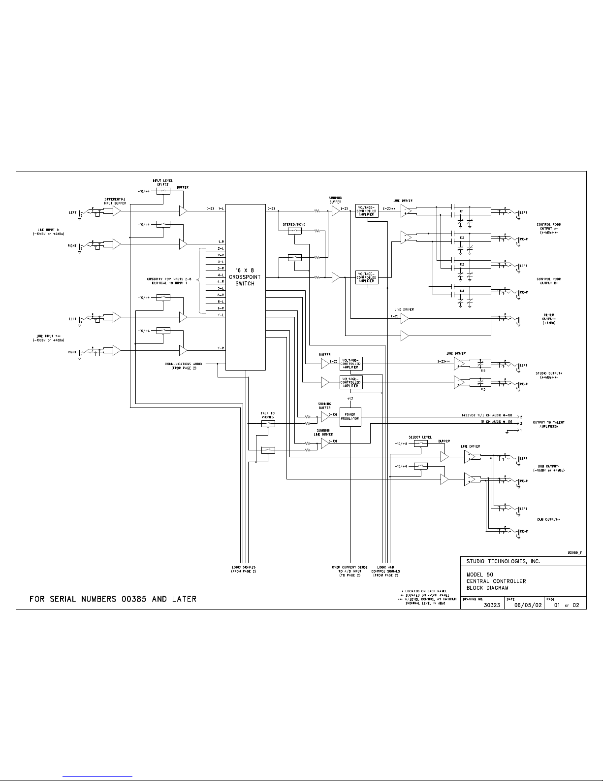
Page 48
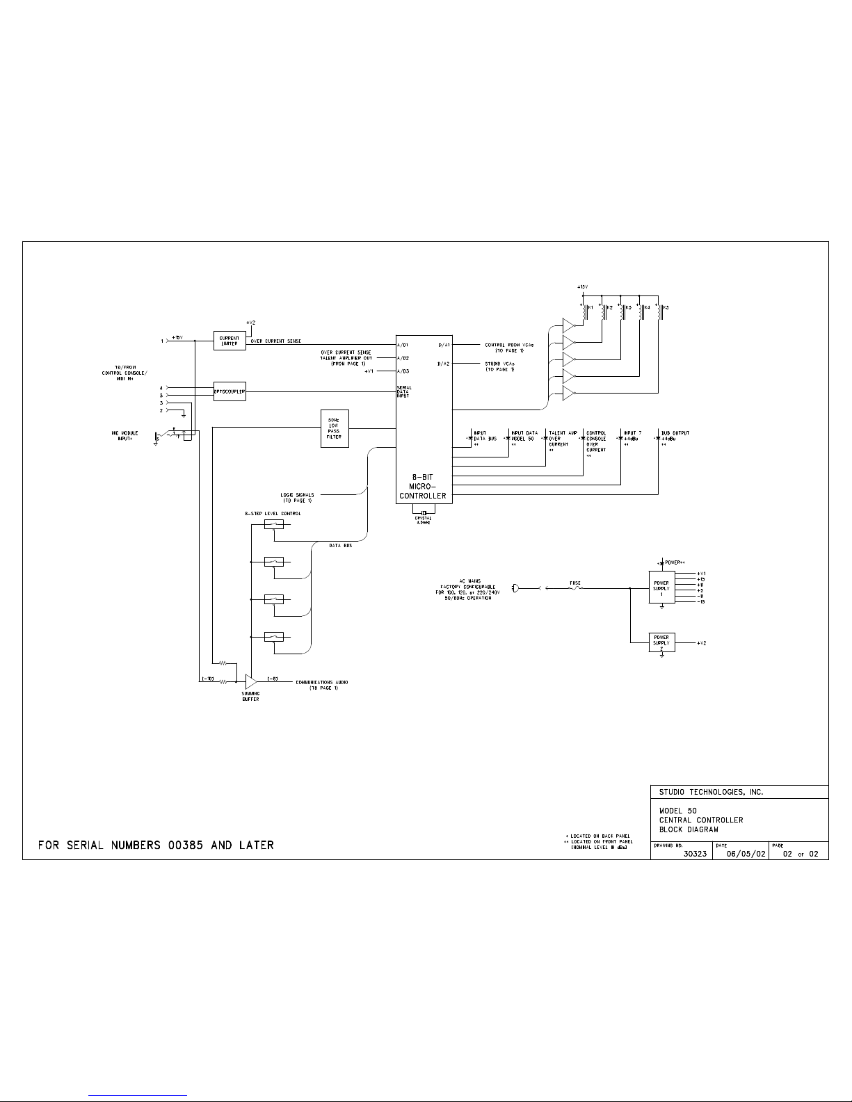
Page 49
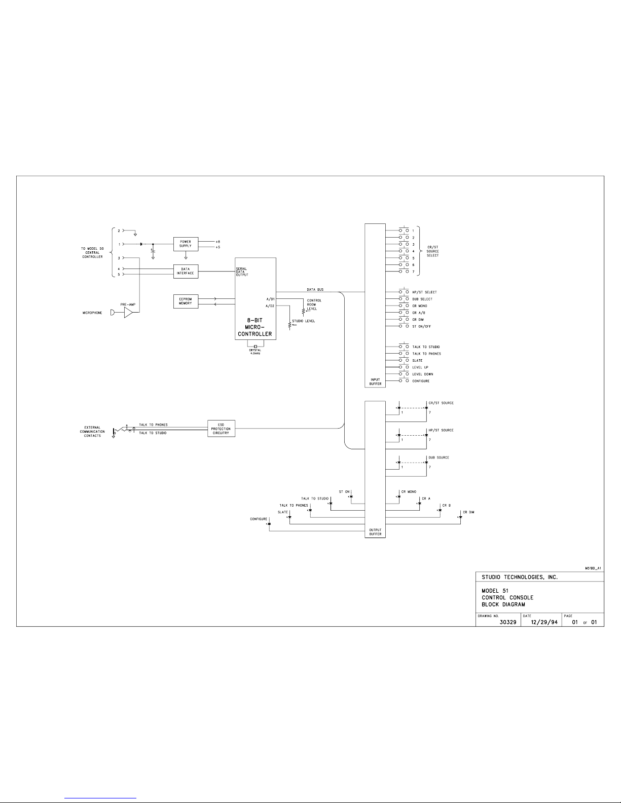
Page 50
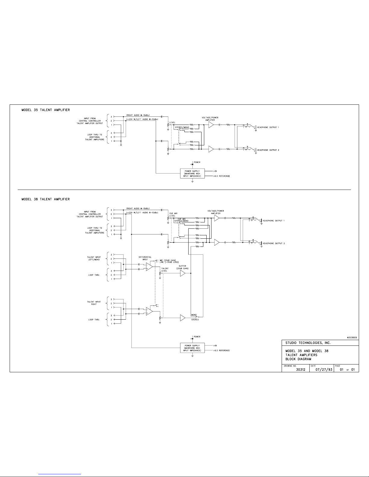
Page 51
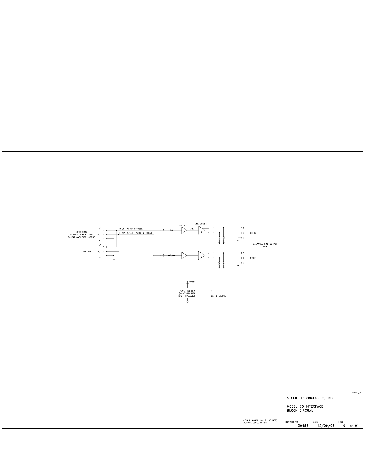
 Loading...