

Page 1
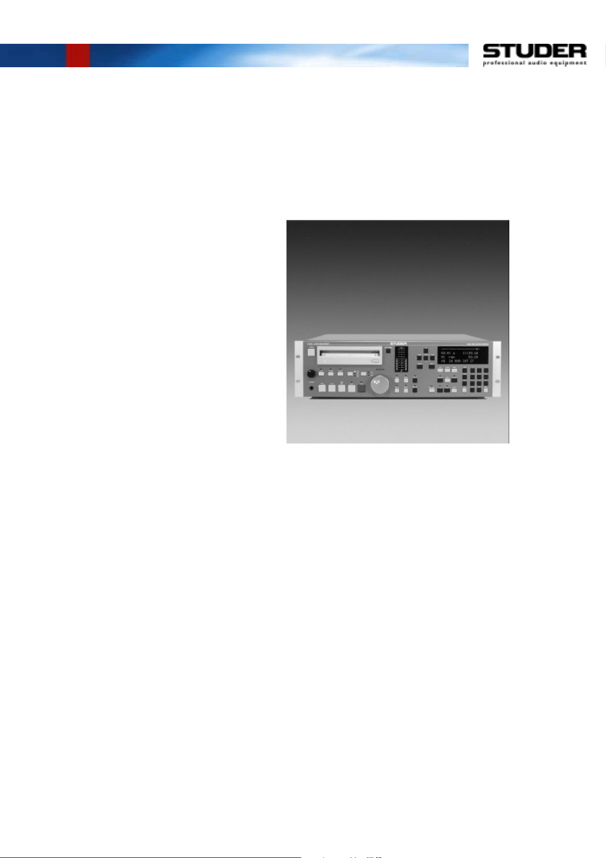
Studer D424
2-Channel MO Disk Recorder
Software Version 1.6
Operating Instructions
Page 2

Prepared and edited by Copyright by Studer Professional Audio GmbH
Studer Professional Audio GmbH Printed in Switzerland
Technical Documentation Order no. 10.27.3803 (Ed. 0402)
Althardstrasse 30
CH-8105 Regensdorf – Switzerland
http://www.studer.ch Subject to change
Studer is a registered trade mark of Studer Professional Audio GmbH, Regensdorf
Page 3
A Safety Information
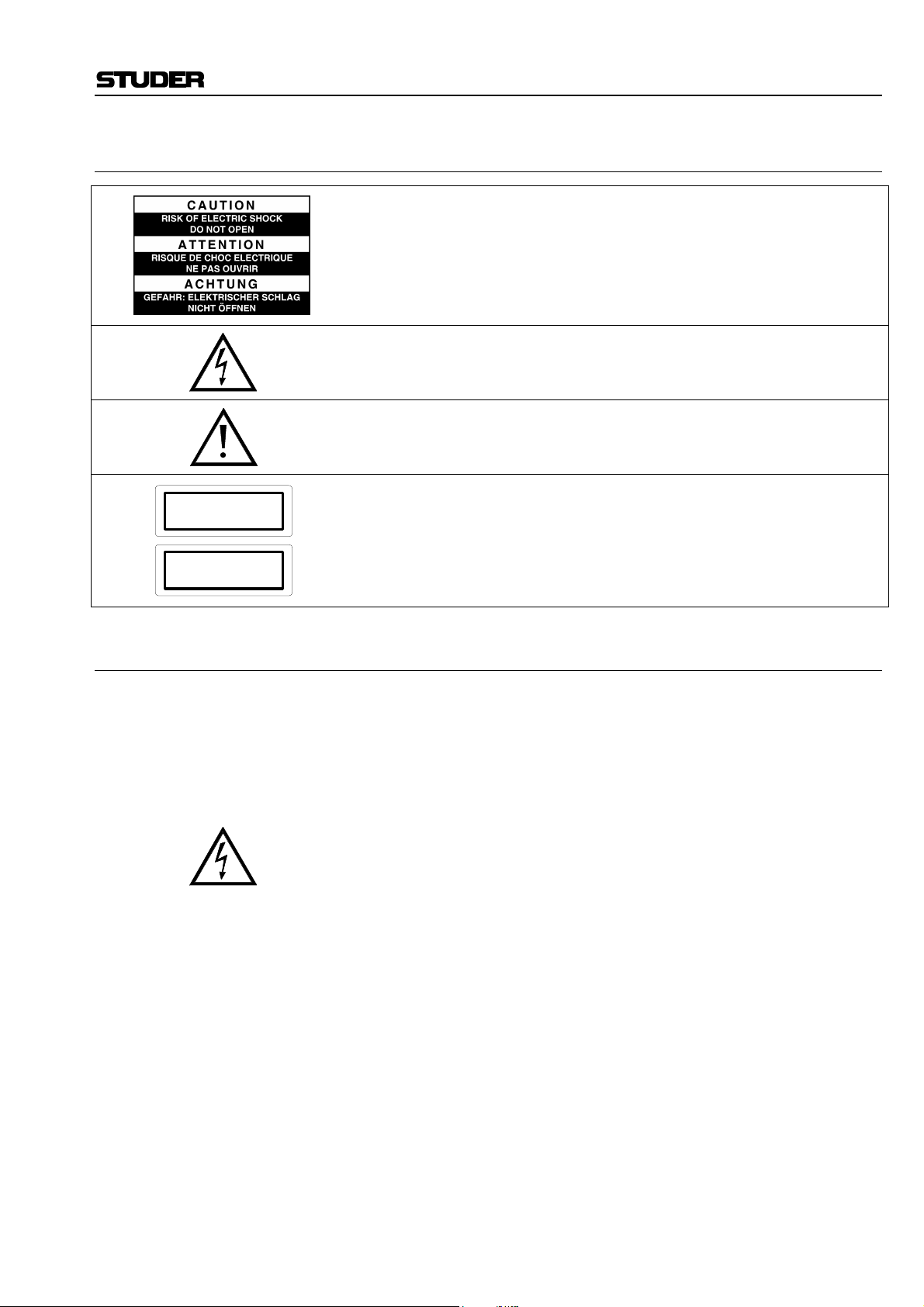
To reduce the risk of electric shock, do not remove covers (or back). No
user-serviceable parts inside. Refer servicing to qualified service personnel.
This symbol is intended to alert the user to presence of un-insulated dan-
gerous voltage within the equipment that may be of sufficient magnitude
to constitute a risk of electric shock to a person.
This symbol is intended to alert the user to the presence of important in-
structions for operating and maintenance in the enclosed documentation.
Safety Information
CLASS I
LED PRODUCT
Assemblies or sub-assemblies of this product can contain opto-electronic
devices. As long as these devices comply with Class I of laser or LED
products according to EN 60825-1:1994, they will not be expressly
CLASS I
LASER PRODUCT
marked on the product. If a special design should be covered by a higher
class of this standard, the device concerned will be marked directly on
the assembly or sub-assembly in accordance with the above standard.
A1 First Aid
In Case of Electric Shock: Separate the person as quickly as possible from the electric power source:
• By switching off the equipment,
• By unplugging or disconnecting the mains cable, or
• By pushing the person away from the power source, using dry insulating
material (such as wood or plastic).
• After having sustained an electric shock, always consult a doctor.
Warning! Do not touch the person or his clothing before the power is turned off,
otherwise you stand the risk of sustaining an electric shock as well!
If the Person is Unconscious: • Check the pulse,
• Reanimate the person if respiration is poor,
• Lay the body down, turn it to one side, call for a doctor immediately.
Date printed: 26.04.04 I
Page 4

Installation
B General Installation Hints
Please consider besides these general hints also any product-specific hints
in the "Installation" chapter of this manual.
B1 Unpacking
Check the equipment for any transport damage. A unit that is mechanically
damaged or that has been penetrated by liquids or foreign objects must not
be connected to the AC power outlet or must be immediately disconnected
by unplugging the power cable. Repairs must only be performed by trained
personnel in accordance with the applicable regulations.
B2 Installation Site
Install the unit in a place where the following conditions are met:
• The temperature and the relative humidity of the environment must be
within the specified limits during operation of the unit. Relevant air values are the ones at the air inlets of the unit.
• Condensation must be avoided. If the unit is installed in a location with
large variation of ambient temperature (e.g. in an OB-van), feasible
measures must be taken before and after operation (for details on this
subject, refer to Appendix 1).
• Unobstructed air flow is essential for proper operation. Air vents of the
unit are a functional part of the design and must not be blocked in any
way during operation (e.g. by objects placed upon them or placement of
the unit on a soft support).
• The unit must not be heated up by external sources of heat radiation
(sunlight, spot lights).
B3 Earthing and Power Supply
Earthing of units with mains supply (class I equipment) is performed via
the protective earth (PE) conductor integrated in the mains cable. Units
with battery operation (< 60 V, class III equipment) must be earthed separately.
Earthing the unit is one of the measures for protection against electrical
shock hazard (dangerous body currents). Hazardous voltage may not only
be caused by a defective power supply insulation, but may also be introduced by the connected audio or control cables.
If the unit is installed with one or several external connections, its earthing
must be provided during operation as well as while the unit is inoperative.
If the earthing could be interrupted via the power supply (e.g. by pulling
the mains plug), an additional, permanent earthing must be installed using
the provided earth terminal.
Avoid ground loops (hum loops) by keeping the loop surface as small as
possible (by consequently guiding the earth conductors in a narrow, parallel way), and reduce the noise current flowing through the loop by inserting
an additional impedance (common-mode choke).
II Date printed: 26.04.04
Page 5

Class I Equipment (Mains Operation)
Installation
Should the equipment be delivered without a matching mains cable, the
latter has to be prepared by a trained person using the attached female plug
(IEC320/C13 or IEC320/C19) with respect to the applicable regulations in
your country.
Before connecting the equipment to the AC power outlet, check that the
local line voltage matches the equipment rating (voltage, frequency) within
the admissible tolerance. The equipment fuses must be rated in accordance
with the specifications on the equipment.
Equipment supplied with a 3-pole appliance inlet (protection conforming to
class I equipment) must be connected to a 3-pole AC power outlet so that
the equipment cabinet is connected to the protective earth.
For information on mains cable strain relief please refer to Appendix 2.
Female plug (IEC320), front-side view: National American Standard:
L (Live) Brown Black
N (Neutral) Blue White
PE (Protective Earth Green/Yellow Green
Class III Equipment (Battery Operation up to 60 VDC)
Equipment of this protection class must be earthed using the provided earth
terminal, if one or more external signals are connected to the unit (see explanation at the beginning of this paragraph).
B4 Electromagnetic Compatibility (EMC)
The unit conforms to the protection requirements relevant to electromagnetic phenomena that are listed in the guidelines 89/336/EC and FCC, part
15.
• The electromagnetic interference generated by the unit is limited in such
a way that other equipment and systems can be operated normally.
• The unit is adequately protected against electromagnetic interference so
that it can operate properly.
The unit has been tested and conforms to the EMC standards of the specified electromagnetic environment, as listed in the following declaration.
The limits of these standards ensure protection of the environment and corresponding noise immunity of the equipment with appropriate probability.
However, a professional installation and integration within the system are
imperative prerequisites for operation without EMC problems.
For this purpose, the following measures must be followed:
• Install the equipment in accordance with the operating instructions. Use
the supplied accessories.
• In the system and in the vicinity where the equipment is installed, use
only components (systems, equipment) that also fulfill the EMC standards for the given environment.
• Use a system grounding concept that satisfies the safety requirements
(class I equipment must be connected with a protective ground conduc-
Date printed: 26.04.04 III
Page 6

Installation/Maintenance/ESD
tor) and that also takes into consideration the EMC requirements. When
deciding between radial, surface, or combined grounding, the advantages and disadvantages should be carefully evaluated in each case.
• Use shielded cables where shielding is specified. The connection of the
shield to the corresponding connector terminal or housing should have a
large surface and be corrosion-proof. Please note that a cable shield
connected only single-ended can act as a transmitting or receiving antenna within the corresponding frequency range.
• Avoid ground loops or reduce their adverse effects by keeping the loop
surface as small as possible, and reduce the noise current flowing
through the loop by inserting an additional impedance (e.g. commonmode choke).
• Reduce electrostatic discharge (ESD) of persons by installing an appropriate floor covering (e.g. a carpet with permanent electrostatic filaments) and by keeping the relative humidity above 30%. Further measures (e.g. conducting floor) are usually unnecessary and only suitable if
used together with corresponding personal equipment.
• When using equipment with touch-sensitive operator controls, please
take care that the surrounding building structure allows for sufficient
capacitive coupling of the operator. This coupling can be improved by
an additional, conducting surface in the operator’s area, connected to the
equipment housing (e.g. metal foil underneath the floor covering, carpet
with conductive backing).
C Maintenance
All air vents and openings for operating elements (faders, rotary knobs)
must be checked on a regular basis, and cleaned in case of dust accumulation. For cleaning, a soft paint-brush or a vacuum cleaner is recommended.
Cleaning the surfaces of the unit is performed with a soft, dry cloth or a
soft brush.
Persistent contamination can be treated with a cloth that is slightly humidified with a mild cleaning solution (soap-suds).
For cleaning display windows, commercially available computer/TV
screen cleaners are suited. Use only a slightly damp (never wet) cloth.
Never use any solvents for cleaning the exterior of the unit! Liquids must
never be sprayed or poured on directly!
For equipment-specific maintenance information please refer to the corresponding chapter in the Operating and Service Instructions manuals.
D Electrostatic Discharge during Maintenance and Repair
Caution: Observe the precautions for handling devices sensitive to electrostatic dis-
charge!
Many semiconductor components are sensitive to electrostatic discharge
(ESD). The life-span of assemblies containing such components can be
drastically reduced by improper handling during maintenance and repair
work. Please observe the following rules when handling ESD sensitive
components:
• ESD sensitive components should only be stored and transported in the
packing material specifically provided for this purpose.
• When performing a repair by replacing complete assemblies, the removed assembly must be sent back to the supplier in the same packing
IV Date printed: 26.04.04
Page 7

E Repair
ESD/Repair
material in which the replacement assembly was shipped. If this should
not be the case, any claim for a possible refund will be null and void.
• Unpacked ESD sensitive components should only be handled in ESD
protected areas (EPA, e.g. area for field service, repair or service bench)
and only be touched by persons who wear a wristlet that is connected to
the ground potential of the repair or service bench by a series resistor.
The equipment to be repaired or serviced as well as all tools and electrically semi-conducting work, storage, and floor mats should also be connected to this ground potential.
• The terminals of ESD sensitive components must not come in uncontrolled contact with electrostatically chargeable (voltage puncture) or
metallic surfaces (discharge shock hazard).
• To prevent undefined transient stress of the components and possible
damage due to inadmissible voltages or compensation currents, electrical connections should only be established or separated when the
equipment is switched off and after any capacitor charges have decayed.
Removal of housing parts, shields, etc. exposes energized parts. For this
reason the following precautions must be observed:
• Maintenance may only be performed by trained personnel in accordance
with the applicable regulations.
• The equipment must be switched off and disconnected from the AC
power outlet before any housing parts are removed.
• Even if the equipment is disconnected from the power outlet, parts with
hazardous charges (e.g. capacitors, picture tubes) must not be touched
until they have been properly discharged. Do not touch hot components
(power semiconductors, heat sinks, etc.) before they have cooled off.
• If maintenance is performed on a unit that is opened and switched on, no
un-insulated circuit components and metallic semiconductor housings
must be touched, neither with your bare hands nor with un-insulated
tools.
Certain components pose additional hazards:
• Explosion hazard from lithium batteries, electrolytic capacitors and
power semiconductors (watch the component’s polarity. Do not short
battery terminals. Replace batteries only by the same type).
• Implosion hazard from evacuated display units.
• Radiation hazard from laser units (non-ionizing), picture tubes (ionizing).
• Caustic effect of display units (LCD) and components containing liquid
electrolyte.
Such components should only be handled by trained personnel who are
properly protected (e.g. safety goggles, gloves).
Date printed: 26.04.04 V
Page 8
Repair/Disposal
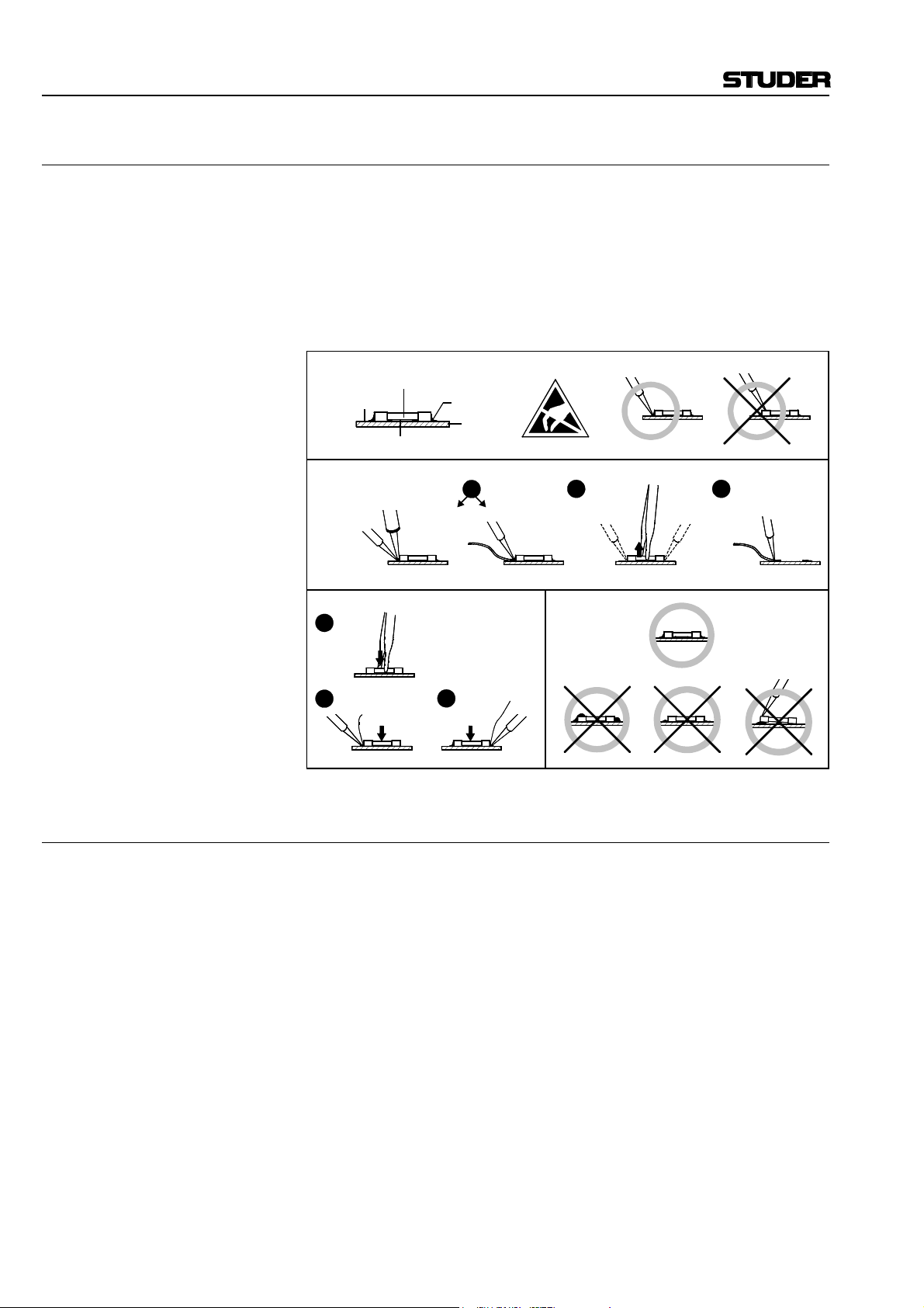
E1 SMD Components
Studer does not keep any commercially available SMD components in
stock. For repair the corresponding devices should be purchased locally.
The specifications of special components can be found in the service manual.
SMD components should only be replaced by skilled specialists using appropriate tools. No warranty claims will be accepted for circuit boards that
have been damaged. Proper and improper SMD soldering joints are illustrated below.
Copper
Track
Dismounting
Soldering
Iron
Mounting
1
Solder
2
Ø 0.5...0.8 mm
SMD
Component
Solder
Adhesive
Desoldering
Iron
Desolder
Wick
3
Heating Time < 3 s per Side
PCB
1
Soldering Iron
32
Desolder
Wick
Heat and Remove Cleaning
Examples
F Disposal
Disposal of Packing Materials The packing materials have been selected with environmental and disposal
issues in mind. All packing material can be recycled. Recycling packing
saves raw materials and reduces the volume of waste.
If you need to dispose of the transport packing materials, please try to use
recyclable means.
Disposal of Used Equipment Used equipment contains valuable raw materials as well as materials that
must be disposed of professionally. Please return your used equipment via
an authorized specialist dealer or via the public waste disposal system, ensuring any material that can be recycled is.
Please take care that your used equipment cannot be abused. To avoid
abuse, delete sensitive data from any data storage media. After having disconnected your used equipment from the mains supply, make sure that the
mains connector and the mains cable are made useless.
VI Date printed: 26.04.04
Page 9

G Declarations of Conformity
G1 Class A Equipment - FCC Notice
This equipment has been tested and found to comply with the limits for a
Class A digital device, pursuant to Part 15 of the FCC Rules. These limits
are designed to provide a reasonable protection against harmful interference when the equipment is operated in a commercial environment. This
equipment generates, uses, and can radiate radio frequency energy and, if
not installed and used in accordance with the instruction manual, may
cause harmful interference to radio communications. Operation of this
equipment in a residential area is likely to cause harmful interference, in
which case the user will be required to correct the interference at his own
expense.
Caution: Any changes or modifications not expressly approved by the manufacturer
could void the user's authority to operate the equipment. Also refer to relevant information in this manual.
G2 CE Declaration of Conformity
Conformity
We,
Studer Professional Audio GmbH,
CH-8105 Regensdorf,
declare under our sole responsibility that the product
Studer D424, Professional 2-Channel MO Disk Recorder
(starting with serial no. 101)
to which this declaration relates, according to following regulations of EU
directives and amendments
• Low Voltage (LVD):
73/23/EEC + 93/68/EEC
• Electromagnetic Compatibility (EMC):
89/336/EEC + 92/31/EEC + 93/68/EEC
is in conformity with the following standards or normative documents:
• Safety:
EN 60950:1992 + A1/A2:1993 (Class I equipment)
• EMC:
EN 50081-1:1992, EN 50082-1:1992
Regensdorf, July 18, 1996
B. Hochstrasser, President P. Fiala, Manager QA
VII
Page 10

Appendix
Appendix 1: Air Temperature and Humidity
General
Normal operation of the unit or system is warranted under the following
ambient conditions defined by EN 60721-3-3, set IE32, value 3K3.
This standard consists of an extensive catalogue of parameters, the most
important of which are: ambient temperature +5...+40 °C, relative humidity
5...85% (i.e., no formation of condensation or ice); absolute humidity
1...25 g/m³; rate of temperature change < 0.5 °C/min. These parameters are
dealt with in the following paragraphs.
Under these conditions the unit or system starts and works without any
problem. Beyond these specifications, possible problems are described in
the following paragraphs.
Ambient Temperature
Units and systems by Studer are generally designed for an ambient temperature range (i.e. temperature of the incoming air) of +5...+40 °C. When
rack mounting the units, the intended air flow and herewith adequate cooling must be provided. The following facts must be considered:
• The admissible ambient temperature range for operation of the semiconductor components is 0 °C to +70 °C (commercial temperature range
for operation).
• The air flow through the installation must provide that the outgoing air
is always cooler than 70 °C.
• Average heat increase of the cooling air shall be 20 K, allowing for an
additional maximum 10 K increase at the hot components.
• In order to dissipate 1 kW with this admissible average heat increase, an
air flow of 2.65 m³/min is required.
Example: A rack dissipating P = 800 W requires an air flow of 0.8 * 2.65 m³/min
which corresponds to 2.12 m³/min.
• If the cooling function of the installation must be monitored (e.g. for fan
failure or illumination with spot lamps), the outgoing air temperature
must be measured directly above the modules at several places within
the rack. The trigger temperature of the sensors should be 65 to 70 °C.
Frost and Dew
The unsealed system parts (connector areas and semiconductor pins) allow
for a minute formation of ice or frost. However, formation of dew visible
with the naked eye will already lead to malfunctions. In practice, reliable
operation can be expected in a temperature range above –15 °C, if the following general rule is considered for putting the cold system into operation:
If the air within the system is cooled down, the relative humidity rises. If it
reaches 100%, condensation will arise, usually in the boundary layer between the air and a cooler surface, together with formation of ice or dew at
sensitive areas of the system (contacts, IC pins, etc.). Once internal condensation occurs, trouble-free operation cannot be guaranteed, independent
of temperature.
VIII Date printed: 26.04.04
Page 11

Appendix
Before putting into operation, the system must be checked for internal formation of condensation or ice. Only with a minute formation of ice, direct
evaporation (sublimation) may be expected; otherwise the system must be
heated and dried while switched off.
A system without visible internal formation of ice or condensation should
be heated up with its own heat dissipation, as homogeneously (and subsequently as slow) as possible; the ambient temperature should then always
be lower than the one of the outgoing air.
If it is absolutely necessary to operate the cold system immediately within
warm ambient air, this air must be dehydrated. In such a case, the absolute
humidity must be so low that the relative humidity, related to the coldest
system surface, always remains below 100%.
Ensure that the enclosed air is as dry as possible when powering off (i.e.
before switching off in winter, aerate the room with cold, dry air, and remove humid objects as clothes from the room).
These relationships are visible from the following climatogram. For a controlled procedure, thermometer and hygrometer as well as a thermometer
within the system will be required.
Example 1: An OB-van having an internal temperature of 20 °C and relative humidity
of 40% is switched off in the evening. If temperature falls below +5 °C,
dew or ice will be forming.
Example 2: An OB-van is heated up in the morning with air of 20 °C and a relative
humidity of 40%. On all parts being cooler than +5 °C, dew or ice will be
forming.
Date printed: 26.04.04 IX
Page 12
Appendix
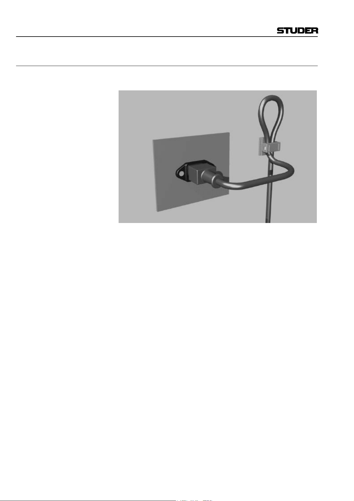
Appendix 2: Mains Connector Strain Relief
For anchoring connectors without a mechanical lock (e.g. IEC mains connectors), we recommend the following arrangement:
Procedure: The cable clamp shipped with your unit is auto-adhesive. For mounting
please follow the rules below:
• The surface to be adhered to must be clean, dry, and free from grease,
oil, or other contaminants. Recommended application temperature range
is 20...40 °C.
• Remove the plastic protective backing from the rear side of the clamp
and apply it firmly to the surface at the desired position. Allow as much
time as possible for curing. The bond continues to develop for as long as
24 hours.
• For improved stability, the clamp should be fixed with a screw. For this
purpose, a self-tapping screw and an M4 bolt and nut are included.
• Place the cable into the clamp as shown in the illustration above and
firmly press down the internal top cover until the cable is fixed.
X Date printed: 26.04.04
Page 13

Appendix 3: Software License
Use of the software is subject to the Studer Professional Audio Software
License Agreement set forth below. Using the software indicates your acceptance of this license agreement. If you do not accept these license terms,
you are not authorized to use this software.
Under the condition and within the scope of the following Terms and Conditions, Studer Professional Audio GmbH (hereinafter “Studer”) grants the
right to use programs developed by Studer as well as those of third parties
which have been installed by Studer on or within its products. References
to the license programs shall be references to the newest release of a license program installed at the Customer’s site.
Programs Covered by the Agreement
License Programs of Studer The following Terms and Conditions grant the right to use all programs of
Studer that are part of the System and/or its options at the time of its delivery to the Customer, as well as the installation software on the original data
disk and the accompanying documentation (“License Material”). In this
Agreement the word “Programs” shall have the meaning of programs and
data written in machine code.
Using the software indicates your acceptance of this license agreement. If
you do not accept these license terms, you are not authorized to use this
software.
Appendix
Programs of Third Parties Programs of third parties are all programs which constitute part of the
Right of Use
System and/or its options at the time of delivery to the Customer but have
not been developed by Studer. The following conditions are applicable to
programs of third parties:
• The right to use third parties’ programs is governed by the License
Agreement attached hereto (if applicable), which is an integral part of
this Agreement. The Customer shall sign any and all License Agreements for all further programs of third parties installed on the system.
The Customer shall be deemed to have received all License Agreements
upon delivery of the system and/or its options.
• Studer shall accept no responsibility or liability for, and gives no warranties (express or implied) as to the programs of third parties. The
Customer waives any and all claims versus Studer for any consequential
damages, which might occur due to defects of these programs.
Principle Studer grants the Customer the non-exclusive right to use the License Ma-
terial in one copy on the system and/or its options as laid down by the
Sales Agreement concluded between the parties and all Terms and Conditions which shall be deemed to form and be read and construed as part of
the Sales Agreement. This right is assignable according to the “Assignability” paragraph hereinafter.
Customized Configurations The Customer is not entitled to alter or develop further the License Mate-
rial except within the expressly permitted configuration possibilities given
by the software installed on the system or elsewhere. All altered programs,
including but not limited to the products altered within the permitted configuration possibilities, are covered by this License Agreement.
Date printed: 26.04.04 XI
Page 14

Appendix
Reverse Engineering Reverse engineering is only permitted with the express consent of Studer.
The consent of Studer can be obtained but is not limited to the case in
which the interface-software can not be provided by Studer. In any case
Studer has to be informed immediately upon complete or partial reverse
engineering.
Copying the License Material The Customer is entitled to make one copy of all or parts of the License
Material as is necessary for the use according to this Agreement, namely
for backup purposes. The Customer shall apply the copyright of Studer
found on the License Material onto all copies made by him. Records shall
be kept by the Customer regarding the amount of copies made and their
place of keeping. The responsibility for the original program and all copies
made lies with the Customer. Studer is entitled to check these records on
first request. Copies not needed anymore have to be destroyed immediately.
Disclosure of License Material The License Material is a business secret of Studer. The Customer shall not
hand out or in any way give access to parts or the complete License Material to third parties nor to publish any part of the License Material without
prior written consent of Studer. The Customer shall protect the License
Material and any copies made according to the paragraph above by appropriate defense measures against unauthorized access. This obligation of
non-disclosure is a perpetual obligation.
Third parties are entitled to have access to the License Material if they use
the License Material at the Customer’s site in compliance with this Agreement.
Under no circumstance are third parties entitled to have access to the installation software on the original data media. The Customer shall safeguard the original data media accordingly.
Assignability The rights granted to the Customer according to this License Agreement
shall only be assignable to a third party together with the transfer of the
system and/or its options and after the prior written consent of Studer.
Rights to License Material
With the exception of the right of use granted by this License Agreement
all proprietary rights to the License Material, especially the ownership and
the intellectual property rights (such as but not limited to patents and copyright) remain with Studer even if alterations, customized changes or
amendments have been made to the License Material.
Studer’s proprietary rights are acknowledged by the Customer. The Customer shall undertake no infringements and make no claims of any patent,
registered design, copyright, trade mark or trade name, or other intellectual
property right.
Warranty, Disclaimer, and Liability
For all issues not covered herewithin, please refer to the “General Terms
and Conditions of Sale and Delivery” that are part of the sales contract.
XII Date printed: 26.04.04
Page 15

D424 MO Recorder
CONTENTS
1 General..................................................................................................................................................................E1/1
1.1 MO Recording.................................................................................................................................................E1/1
1.2 The Medium – Magneto-Optical Disks............................................................................................................E1/2
1.2.1 Disk Standards ........................................................................................................................................E1/2
1.2.2 Disk Formatting.......................................................................................................................................E1/3
1.2.3 Disk Capacities ........................................................................................................................................ E1/3
1.2.4 Disk Handling ......................................................................................................................................... E1/4
1.3 File Systems, File Formats, Audio Files........................................................................................................... E1/5
1.3.1 Takes, Indices, and Sequences ................................................................................................................. E1/5
1.3.2 Non-Destructive Editing.......................................................................................................................... E1/7
1.4 Utilization for the Purpose Intended ................................................................................................................ E1/8
1.5 Copyright........................................................................................................................................................E1/8
1.6 First Steps.......................................................................................................................................................E1/8
1.6.1 Unpacking and Inspection........................................................................................................................ E1/8
1.6.2 Installation .............................................................................................................................................. E1/8
1.6.3 Adjustments, Repair ................................................................................................................................ E1/9
1.6.4 Accessories, Options ................................................................................................................................ E1/9
1.6.5 Connector Field..................................................................................................................................... E1/10
1.6.6 Connector Pin Assignments................................................................................................................... E1/11
1.7 Technical Specifications................................................................................................................................ E1/13
1.7.1 Drive System ......................................................................................................................................... E1/13
1.7.2 Recording Formats.................................................................................................................................E1/13
1.7.3 Audio Processing................................................................................................................................... E1/13
1.7.4 Audio Input/ Output............................................................................................................................... E1/13
1.7.5 Synchronization..................................................................................................................................... E1/14
1.7.6 Timecode............................................................................................................................................... E1/14
1.7.7 Control Interfaces.................................................................................................................................. E1/14
1.7.8 Power Supply......................................................................................................................................... E1/15
1.7.9 Operating Conditions............................................................................................................................. E1/15
1.7.10 Standards............................................................................................................................................... E1/15
1.7.11 Physical Dimensions.............................................................................................................................. E1/15
1.8 Syntax Used in this Manual........................................................................................................................... E1/16
2 Operating elements...............................................................................................................................................E2/1
2.1 General ........................................................................................................................................................... E2/2
2.2 Transport Section............................................................................................................................................E2/2
2.3 Editing Section ................................................................................................................................................ E2/3
2.4 Keyboard and Register Section ........................................................................................................................ E2/3
2.5 Display and Menu Section............................................................................................................................... E2/4
2.6 Additional Functions (Desktop Controller only) .............................................................................................. E2/4
Date printed: 19.10.01 SW V 1.6 Contents E0/1
Page 16

D424 MO Recorder
3 Getting Started Quickly .......................................................................................................................................E3/1
3.1 Recording New Takes From an Analog Source................................................................................................ E3/1
3.1.1 Installation and Settings .......................................................................................................................... E3/1
3.1.2 Start Recording........................................................................................................................................ E3/1
3.2 Recording New Takes From a Digital Source .................................................................................................. E3/2
3.2.1 Installation and Settings .......................................................................................................................... E3/2
3.2.2 Start Recording........................................................................................................................................ E3/2
3.3 Playing Pre-Recorded Disks ............................................................................................................................ E3/3
3.3.1 Installation and Settings .......................................................................................................................... E3/3
3.3.2 Position ................................................................................................................................................... E3/3
3.3.3 PLAY and STOP..................................................................................................................................... E3/3
3.3.4 Skip to Take and Index Markers.............................................................................................................. E3/3
3.3.5 CUE and SHUTTLE................................................................................................................................ E3/3
3.3.6 LOCATE.................................................................................................................................................E3/4
3.3.7 Setting Markers....................................................................................................................................... E3/4
3.4 Editing ............................................................................................................................................................ E3/5
3.4.1 Before You Start Editing ......................................................................................................................... E3/5
3.4.2 Cut Out or Erase an Element – Cut/ Erase Editing................................................................................... E3/5
3.4.3 Move or Duplicate an Element – Insert Editing ....................................................................................... E3/6
3.5 Insert Recording.............................................................................................................................................. E3/7
3.5.1 Before You Start Recording..................................................................................................................... E3/7
3.5.2 Manual Insert Recording......................................................................................................................... E3/7
3.5.3 Auto Insert Recording.............................................................................................................................. E3/7
3.6 Working with Sequences................................................................................................................................. E3/8
3.6.1 Change the Current Sequence.................................................................................................................. E3/8
3.6.2 Create a New Sequence............................................................................................................................ E3/8
3.6.3 Modify a Sequence................................................................................................................................... E3/8
3.6.4 Copy a Sequence...................................................................................................................................... E3/9
3.6.5 Delete a Sequence .................................................................................................................................... E3/9
3.7 CD Transfer and Disk Copies ........................................................................................................................ E3/10
3.7.1 Before you Start the Transfer ................................................................................................................. E3/10
3.7.2 Creating a CD with an External SCSI CD Writer (e.g. Studer D741) ..................................................... E3/10
3.7.3 Copying a CD to the D424..................................................................................................................... E3/11
3.7.4 Copying to/ from Other MO Disks......................................................................................................... E3/11
3.8 Working with Timecode................................................................................................................................ E3/12
3.8.1 Recording Timecode .............................................................................................................................. E3/12
3.8.2 Playing Back Timecode ......................................................................................................................... E3/12
3.8.3 Chasing to Timecode............................................................................................................................. E3/12
3.9 The Desktop Controller................................................................................................................................. E3/13
3.9.1 Installation and Settings ........................................................................................................................ E3/13
3.9.2 Operation Enhancements ....................................................................................................................... E3/13
3.10 The Parallel Port with Fader Start Operation................................................................................................. E3/14
3.10.1 Signal List............................................................................................................................................. E3/14
3.10.2 Fader Start............................................................................................................................................. E3/14
3.11 The Setup Menu............................................................................................................................................ E3/15
E0/2 Contents SW V 1.6 Date printed: 19.10.01
Page 17

D424 MO Recorder
4 Operation ..............................................................................................................................................................E4/1
4.1 System Configuration...................................................................................................................................... E4/1
4.1.1 Recording Formats...................................................................................................................................E4/1
4.1.2 Audio Input ............................................................................................................................................. E4/2
4.1.3 Reference Clock Source ........................................................................................................................... E4/2
4.1.4 Other Parameters ..................................................................................................................................... E4/3
4.2 Display and Register Functions ....................................................................................................................... E4/4
4.2.1 Display Information and Formats.............................................................................................................E4/4
4.2.2 Using General Purpose Registers ............................................................................................................. E4/6
4.3 Basic Transport Operation ............................................................................................................................... E4/7
4.3.1 The Current Position................................................................................................................................ E4/7
4.3.2 Playback and Stop.................................................................................................................................... E4/9
4.3.3 Skipping to Take and Index Markers.......................................................................................................E4/9
4.3.4 The CUE and SHUTTLE Modes .............................................................................................................. E4/9
4.3.5 Locating to a Random Position .............................................................................................................. E4/10
4.4 Recording...................................................................................................................................................... E4/11
4.4.1 The D424 Recording Modes .................................................................................................................. E4/11
4.4.2 Channel Assignments............................................................................................................................ E4/12
4.4.3 Rehearse Mode...................................................................................................................................... E4/12
4.4.4 Meters ................................................................................................................................................... E4/13
4.4.5 Adjusting the Analog Input Level .......................................................................................................... E4/13
4.4.6 Before You Start Recording................................................................................................................... E4/13
4.4.7 Assemble Recording.............................................................................................................................. E4/14
4.4.8 Insert Recording.................................................................................................................................... E4/14
4.4.9 Auto Insert Recording............................................................................................................................ E4/15
4.5 Editing.......................................................................................................................................................... E4/16
4.5.1 Setting IN and OUT Points.................................................................................................................... E4/16
4.5.2 The CUT Function................................................................................................................................. E4/17
4.5.3 The ERASE Function ............................................................................................................................ E4/18
4.5.4 The INSERT Function........................................................................................................................... E4/18
4.5.5 Combined Editing Processes.................................................................................................................. E4/19
4.5.6 The PREVIEW Function ....................................................................................................................... E4/19
4.6 Sequence Editing...........................................................................................................................................E4/21
4.6.1 Selecting a Sequence.............................................................................................................................. E4/21
4.6.2 Creating a New Sequence ...................................................................................................................... E4/21
4.6.3 Deleting a Sequence............................................................................................................................... E4/21
4.6.4 Editing a Sequence ................................................................................................................................ E4/22
4.7 CD Transfer and Disk Copies ........................................................................................................................ E4/24
4.7.1 Configuration ........................................................................................................................................ E4/24
4.7.2 Transfer to a CD Writer......................................................................................................................... E4/24
4.7.3 Copying a CD to the D424 ..................................................................................................................... E4/26
4.7.4 Copying to/from Other Disks................................................................................................................. E4/27
4.7.5 Transfer Parameters............................................................................................................................... E4/28
4.7.6 SCSI Addresses ..................................................................................................................................... E4/29
4.8 Backup Copies .............................................................................................................................................. E4/30
4.8.1 Sequence Backup................................................................................................................................... E4/30
4.8.2 Disk Backup.......................................................................................................................................... E4/31
4.9 Data Exchange with SADiE® Workstations ................................................................................................... E4/32
4.9.1 DAW Configuration .............................................................................................................................. E4/32
4.9.2 Importing D424 Disks to the DAW........................................................................................................ E4/32
4.9.3 Importing SADiE® Disks to the D424 .................................................................................................... E4/33
Date printed: 19.10.01 SW V 1.6 Contents E0/3
Page 18

D424 MO Recorder
4.10 Setup Menu................................................................................................................................................... E4/34
4.10.1 Accessing and Modifying Menu Items................................................................................................... E4/34
4.10.2 Overview............................................................................................................................................... E4/35
4.10.3 Menu 1, CONFIG (System Configuration)............................................................................................. E4/36
4.10.4 Menu 2, REF & INP (Reference & Input Parameters) ............................................................................ E4/37
4.10.5 Menu 3, AUDIO (Audio Parameters)..................................................................................................... E4/38
4.10.6 Menu 4, TRANSPORT (Transport & Display Parameters)..................................................................... E4/39
4.10.7 Menu 5, DISK (Disk & Sequence Utilities)............................................................................................ E4/40
4.10.8 Menu 6, COPY (Copy Utilities)............................................................................................................. E4/42
4.10.9 Menu 7, SERVICE (Service Utilities).................................................................................................... E4/44
4.11 Desktop Controller........................................................................................................................................ E4/45
4.11.1 Configuration ........................................................................................................................................ E4/45
4.11.2 Operation .............................................................................................................................................. E4/45
4.12 Parallel Port and Fader Start Operation ......................................................................................................... E4/46
4.12.1 Specifications ........................................................................................................................................ E4/46
4.12.2 Signal Description ................................................................................................................................. E4/46
4.12.3 Fader Start............................................................................................................................................. E4/47
4.13 Serial Remote Operation ............................................................................................................................... E4/48
4.13.1 Command List....................................................................................................................................... E4/48
5 Troubleshooting ....................................................................................................................................................E5/1
5.1 Error Messages ............................................................................................................................................... E5/1
5.2 Modifying the D424 SCSI Address.................................................................................................................. E5/3
6 Appendix...............................................................................................................................................................E6/1
6.1 Serial Remote Protocol.................................................................................................................................... E5/1
6.1.1 RS422 9-pin Protocol (Sony-Compatible) ................................................................................................ E5/1
6.1.2 Communication Format........................................................................................................................... E5/1
6.1.3 Hardware Layer ....................................................................................................................................... E5/2
6.1.4 Messages................................................................................................................................................. E5/2
6.1.5 Command List......................................................................................................................................... E5/4
6.1.6 Command Messages................................................................................................................................ E5/5
6.2 Drive Installation Instructions......................................................................................................................... E5/7
6.2.1 MO Drive Kit 2.6 GB (ISO).....................................................................................................................E5/7
6.3 Hardware Configuration (Jumper and DIP Switch Settings) ............................................................................ E5/8
6.3.1 Motherboard............................................................................................................................................E5/8
6.3.2 Core ........................................................................................................................................................ E5/8
E0/4 Contents SW V 1.6 Date printed: 19.10.01
Page 19

1 GENERAL
1.1 MO Recording
D424 MO Recorder
For a long time, analog tape recording has been the standard recording technology in the professional audio industry. The step into the digital audio era
has been done a few years ago with the introduction of digital tape recorders, such as DASH and R-DAT machines. Another important evolution was
pushed by the computer industry: Hard disk-based workstations record on
fast, direct-access media, which are also capable for later editing without
destroying the original information.
Beginning with the consumer format CD, a removable medium with excellent price and archiving characteristics, the optical disk became in the
meantime a reliable recording media standard, in audio and computer industry.
Taking the advantages of the above approaches:
• Well accepted and easy-to-understand surface of a dedicated audio recorder,
• Versatile and future-proof technology, based on standard data storage devices (SCSI-2),
• Removable medium with very good archiving characteristics and the capability for direct access editing,
the Studer D424-2 MO recorder has been designed to be integrated into
today's and future environments, combined with analog and digital audio
processing and automation. It is ready to follow the rapid evolution of recording technology, without neglecting the needs of the professional user.
Date printed: 19.10.01 SW V 1.6 General E1/1
Page 20
D424 MO Recorder
1.2 The Medium – Magneto-Optical Disks
1.2.1 Disk Standards
The D424 MO recorder with ISO drive is equipped with a 5.25" MO drive
capable of reading and writing to the standard double-sided 5.25" disk types
listed below. Only high-quality disks should be used for the D424 application. Please contact your Studer representative for information on the recommended suppliers.
1.2 GB (512 bytes/sector) available on request
2.3 GB (512 bytes/sector) available on request
1.3 GB (1024 bytes/sector) available on request
2.6 GB (1024 bytes/sector) Order No. 15.622.260.13
4.8 GB (1024 bytes/sector) available on request
5.2 GB (2048 bytes/sector) available on request
The D424 will automatically recognize the type of the disk being inserted.
Direct-overwrite (LIM-DOW) type disks are only supported when the D424
is equipped with a F-541-DW drive.
1.2.2 Disk Formatting
New disks are preformatted from the manufacturer. This process is called
“low-level formatting”. It is only useful after having cleaned a disk which
had numerous defective blocks. Low-level formatting will then re-check
every bit on the disk for validity, which can take up to 40 minutes.
In order to start recording, the D424 only has to add the basic system files.
Building up a DOS system and installing the basic D424 files is called
“high-level formatting”, or simply “formatting”. This process takes only a
few seconds.
After inserting a new, empty disk for the first time, the D424 will automatically ask for formatting. Any prerecorded disk may be re-formatted at any
time. This is a fast and direct way to delete the whole contents of a disk.
E1/2 General SW V 1.6 Date printed: 19.10.01
Page 21

1.2.3 Disk Capacities
Notes: All 5.25" disks are double-sided. Each side provides the stereo capacity
D424 MO Recorder
Depending on disk type, sampling rate, and recording format, the recording
capacity will vary. The following table shows some examples of the recording capacities (stereo, per side):
Disk type 44.1 kHz / 16 bit 48 kHz / 16 bit 48 kHz / 24 bit
1.2 GB ISO 55 min 50 min 34 min
1.3 GB ISO 60 min 55 min 37 min
2.3 GB ISO 1 h 45 min 1 h 37 min 1 h 5 min
2.6 GB ISO 2 h 1 h 50 min 1 h 15 min
4.8 / 5.2 GB ISO 3 h 15 min 3 h 2 h
listed above.
Because of the DOS operating system, a maximum of 2 GB can be used;
4.8 and 5.2 GB disks are automatically formatted with a maximum partition.
With 1.2 and 1.3 GB disks, the insert recording modes are limited to 16 and
20 bit resolution. For assemble recording and editing there is no such limitation.
Date printed: 19.10.01 SW V 1.6 General E1/3
Page 22
D424 MO Recorder
1.2.4 Disk Handling
Disks can be write-protected by sliding the appropriate tab to the “data
protect” position (see manufacturer's information).
DATA PROTECT
The magneto-optical medium is very reliable. Nevertheless, there are some
recommendations for disk storage and handling:
• Always store a disk in its case.
• Keep the disk cartridges away from sources of heat, excessive dust, or
moisture.
Please, follow also the information of the disk manufacturer.
After being exposed to a dusty environment, some blocks may be marked as
defective during recording. The MO drive will automatically assign spare
blocks for storing the affected audio information.
The D424 will check a disk when set to RECORD READY. A warning
message will be displayed if more than 60 grown defective sectors were
found.
When starting with a new production, empty disks should not report any
defective blocks. It is therefore recommended to clean empty disks with appropriate tools when encountering such warning messages. After a subsequent low-level formatting process, the disk will again be in perfect shape
for further recordings.
If the number of reported defective blocks is increasing notably, any further
recording and editing should be avoided. Backup your data before resuming
your session.
Please contact your disk supplier or Studer for detailed information on accessories as disk cleaning kits.
E1/4 General SW V 1.6 Date printed: 19.10.01
Page 23

1.3 File Systems, File Formats, Audio Files
The D424 MO-recorder is based on a SCSI-controlled magneto-optical
drive, and standard ISO disks as storage medium. The same drives and disks
are used in computer applications for storing and archiving.
By using the same file system and formats as MS-DOS based computer
platforms, disks which were recorded with a D424 can be played by all
DOS based systems – from simple multimedia computers to fully professional audio workstations.
The D424 is storing all audio information to sound files in standard Microsoft Wave format (*.WAV), including all relevant recording parameters, as
sampling rate, word length, and number of channels.
All further information on the structure of a session as well as all editing
information are kept in separate sequence files (*.seq), also known under the
name Edit Decision List (EDL).
1.3.1 Takes, Indices, and Sequences
D424 MO Recorder
When working with the D424, you don't have to care for sound files, directories, or disk structures and the like; the following definitions, however, are
important for your recording, editing, and playback work.
The recorded material is subdivided into takes and indices.
• Every time you start recording, a new take is created.
• Place additional take markers during a long recording session. In a concert
you may mark the begin of a new song. This will save time for creating the
definitive markers when editing later.
• Store additional index markers at positions which have to be edited. Later,
you will be able to address them directly, without the need for searching.
• During the subsequent editing session, all markers having been previously
set can be deleted or moved. New ones can be set in order to prepare your
project for transferring to a CD, with all desired take and index markers.
When you start working with a new project, all settings and editing information will be stored to the currently selected sequence. Only one sequence
can be active at a time, which is called the “Current Sequence”.
• When you start recording on a new disk, a first sequence will be created.
You will stay with this first sequence until you switch to a new one.
• Create a new, empty sequence for a different project. Start recording and do
your editing session in a separate environment. It is very easy to switch between different sequences.
• You can have several sequences for a single project – do your basic editing
first, copy the current sequence to a new one, and continue with your session. You will have access to the basic version at any time.
• Make different versions of an original recording. You can decide at the end
of your projects, which one you would like to keep – or keep all of them.
Sequences do not require much storage capacity.
Date printed: 19.10.01 SW V 1.6 General E1/5
Page 24
D424 MO Recorder
Takes, Indices: Insert a new, empty disk, set the channels ready, and press REC+PLAY.
The first take in the initial sequence 1 will be recorded. Each time you start
recording, a new take is created, which is given a numbered take marker at
its beginning automatically.
After having recorded three audio takes, the contents of the disk will look
like this:
1 2 3
take 1 take 2 take 3
The current sequence now consists of three takes. Simply record one more
take, and you will end up with:
1 2 3 4
take 1 take 2 take 3 take 4
Whenever there is a need for marking certain points within a take, or to
subdivide a single take into smaller parts, you can create indices by freely
placing index or take markers anywhere within your sequence, either on-line
during recording, or later when editing.
Take 2 can be divided into two separate takes by placing an additional
marker. The new take marker gets number 5, which is the next free number
in the current sequence. In addition, a certain position in take 4 is marked
with an index.
1 2 5 3 4.1 4.2
take 1 take 2 take 5 take 3 take 4
After having placed these markers, you can not only skip from one original
take to the next one, like with a CD player, but also skip to the new markers.
In the example above, the skip sequence is: 1 – 2 – 5 – 3 – 4.1 – 4.2
All the markers can simply be deleted if they are not required anymore. In
case of deleting the take markers 3 and 5 in the above example, the takes 2,
5, and 3 would be joined to a new take. The result would be like this:
1 2 4.1 4.2
take 1 take 2 take 4
Finally, markers can be moved, to adjust the take structure of the existing
source material, e.g. to define the position of the tracks and indices of a CD,
or to prepare precise start positions for on-air broadcasting.
After moving the begin of take 2, the above sequence will look like this:
1 2 4.1 4.2
take 1 take 2 take 4
E1/6 General SW V 1.6 Date printed: 19.10.01
Page 25

D424 MO Recorder
Sequences: If it is necessary to make another production with the same recorded mate-
rial, a new sequence is defined. In the following example, only the takes 2,
3, and 4 should be edited, but in reverse order.
1 2 3 4
take 1 take 2 take 3 take 4
For this purpose, create a new sequence with the Sequence Editing feature,
insert the required takes in their new order (takes 4, 3, and 2), and the new
sequence will be:
4 3 2
take 4 take 3 take 2
You can now start with further editing, like changing markers, renumbering,
cutting or re-arranging audio information, or adjusting levels.
With a few keystrokes you can switch to another available sequence on the
disk, and start playing, recording, or editing.
Note: Creating new sequences does not need additional audio file capacity on a
disk. There is only a new small EDL file, describing how to play the same
audio data in a different way.
1.3.2 Non-Destructive Editing
The D424 is providing non-destructive editing. Because all editing processes
are simply instructions on how to play the original sound files, the original
audio data remain untouched during the whole editing process.
The following processes therefore only modify the sequence data, not the
original audio data:
• Creating, deleting or moving markers.
• Deleting, erasing and inserting audio elements.
• Changing the order of takes.
• Adjusting output levels.
It is possible to have several sequences on the same disk, which represent
different variations of the same basic audio material. Each sequence stores
the editing data into its own sequence file, but will make use of the same
audio files.
Without explicitly deleting sound files, which has to be done with a separate
menu utility, the original data can be re-used at any time. It is hardly possible to delete audio data by accident.
Date printed: 19.10.01 SW V 1.6 General E1/7
Page 26
D424 MO Recorder
1.4 Utilization for the Purpose Intended
The Studer D424 is a Disk recorder intended for professional use. It is designed for recording on MO disks.
It is presumed that the unit is operated only by trained personnel. Servicing is reserved to skilled technicians.
The electrical connections may be connected only to the voltages and signals designed in this manual.
1.5 Copyright
Copies of pre-recorded Material:
Please consider that copying pre-recorded information is only allowed
with the approval of the authorized copyright holders of the original material.
1.6 First Steps
1.6.1 Unpacking and Inspection
Your new MO recorder is shipped in a special packing which protects the
unit against mechanical shock during transit. Care should be exercised when
unpacking so that its surfaces do not get marred.
Verify that the content of the packing agrees with the items listed on the
enclosed shipping list.
Check the condition of the equipment for signs of shipping damage. If there
should be any complaints you should immediately notify the forwarding
agent and your nearest Studer distributor.
Please retain the original packing material because it offers the best protection in case your equipment ever needs to be transported.
1.6.2 Installation
Power Connection: The attached female IEC 320/C 13 mains cable socket has to be connected
to an appropriate mains cable by a trained technician with respect to your
local regulations. Refer to the “Installation, Operation, and Waste Disposal” section at the beginning of this manual.
Maintenance work inside the unit must be performed by a trained technician.
Humidity: Do not use the unit near any source of moisture or in excessively humid
environments.
Ventilation: When installing the unit in a rack or any other location, be sure that there is
adequate ventilation. The recorder should be situated so that its location or
position does not interfere with its proper ventilation.
The ambient temperature of the D424 must not exceed 35 °C, otherwise the
longevity of the mechanism and of the disk drive might be drastically reduced.
E1/8 General SW V 1.6 Date printed: 19.10.01
Page 27

D424 MO Recorder
1.6.3 Adjustments, Repair
Danger: All internal adjustments as well as repair work on this product are to be
performed by skilled technicians!
During service work dangerous laser radiation can occur, so the appropriate precautions must be taken.
Primary Fuse: The primary fuse (F 4 A H 250 V, 5 × 20 mm) is located inside the unit.
Therefore only skilled technicians are authorized to replace the fuse.
1.6.4 Accessories, Options
Accessories Shipped with the D424: 1 Operating manual (English) Order No. 10.27.3803
1 Female mains connector (IEC 320/C 13) Order No. 54.42.1050
1 MO Disk
1 Hexagon pin spanner 2.5 mm Order No. 98.00.2023
2 Fuses F 4 A, 250 V Order No. 51.01.0156
D424 Options: Desktop Controller Order No. 20.866.500.00
Recording Media: MO Disk 2.6 GB ISO Order No. 15.622.260.13
(Other capacities available on request)
Date printed: 19.10.01 SW V 1.6 General E1/9
Page 28

D424 MO Recorder
1.6.5 Connector Field
[3] [11] [9] [5] [6][8]
OUT 1
LINE
OUT 2
IN 1
LINE
IN 2
SCSI-2
SERIAL
CONTROLLER
CONTROLLER
PARALLEL
VIDEOIN OUT
75 Ω
OFF
WORDCLOCKIN OUT
75 Ω
OFF
IN OUTSYNC AES/EBU TCIN OUTAES/EBU
CAUTION
RISK OF ELECTRIC SHOCK
DO NOT OPEN
ATTENTION
RISQUE DE CHOC ELECTRIQUE
NE PAS OUVRIR
ACHTUNG
GEFAHR: ELEKTRISCHER SCHLAG
NICHT ÖFFNEN
[2] [10] [4] [7] [1]
[1] AC PLUG AC power connector IEC 320/C 14
for mains supply 100...240 V, 50...60 Hz
[2] AES/EBU IN/OUT AES/EBU digital audio I/O
Input (XLR-3, female) and output (XLR-3, male)
[3] ANALOG IN/OUT Analog audio I/O
(optional) Input CH1/CH2 (XLR-3 female) and output CH1/CH2 (XLR-3 male)
100 - 240 V
~
[4] SYNC AES/EBU AES-11 digital audio reference
Input (XLR-3, female)
[5] VIDEO REFERENCE Composite Video Reference, 75 Ω termination selectable
Input and output (loop through), BNC connectors
[6] WORD CLOCK Digital word clock, 75 Ω termination selectable
Input and output, BNC connectors
[7] TIME CODE SMPTE/EBU longitudinal timecode
Input (XLR-3 female), and output (XLR-3 male)
[8] SERIAL Serial remote RS-422, Input
(SONY 9-pin compatible)
[9] CONTROLLER Desktop Controller, input and output (loop through)
For Desktop Controller operation and multi-machine configurations
[10] PARALLEL Parallel GPI port, input/output
[11] SCSI-2 SCSI-2 port
For external drive configurations and SCSI data transfer
E1/10 General SW V 1.6 Date printed: 19.10.01
Page 29
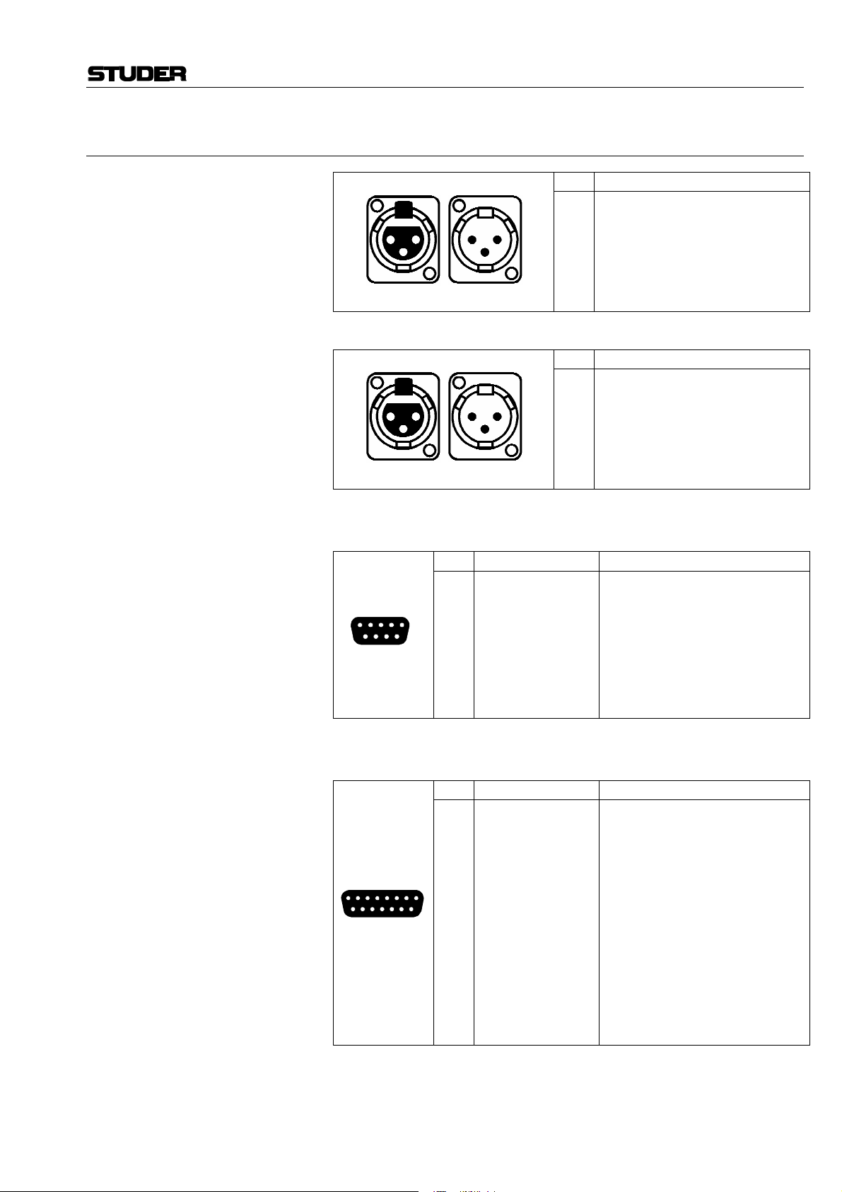
1.6.6 Connector Pin Assignments
D424 MO Recorder
INPUT/OUTPUT LEFT/RIGHT
AES/EBU DIGITAL IN/OUT
SERIAL 9 pin D-type, female
IN OUT
1
2
3
1 2
3
XLR-3f XLR-3m
IN OUT
1
2
3
1 2
3
XLR-3f XLR-3m
Pin Signal Function
1
FGND
2
15
69
TXA
3
RXB
4
RXC
5
VCC
6
TXC
7
TXB
8
RXA
9
FGND
Pin Signal
1
Ground
2
Line A ("hot")
3
Line B ("cold")
Pin Signal
1
Ground
2
Line A ("hot")
3
Line B ("cold")
Frame ground
Transmit A (inverted)
Receive B
Receive common
Supply voltage +24 V, switchable
Transmit common
Transmit B
Receive A (inverted)
Frame ground
CONTROLLER 15 pin D-type, female
Pin Signal Function
1
PHL–
2
PHR–
3
AGND
4
REMT
5
8 1
915
Date printed: 19.10.01 SW V 1.6 General E1/11
6
7
8
9
10
11
12
13
14
15
REMR
STSTR
SYNCBUS
DGND
PHL+
PHR+
+24 V
IREMT
IREMR
ISTSTR
ISYNCBUS
Phones left, inverted
Phones right, inverted
Analog ground
Rem bus transmit
Rem bus receive
Start signal
Sync bus
Digital ground
Phones left
Phones right
Supply voltage
Rem bus transmit, inverted
Rem bus receive, inverted
Start signal, inverted
Sync bus, inverted
Page 30
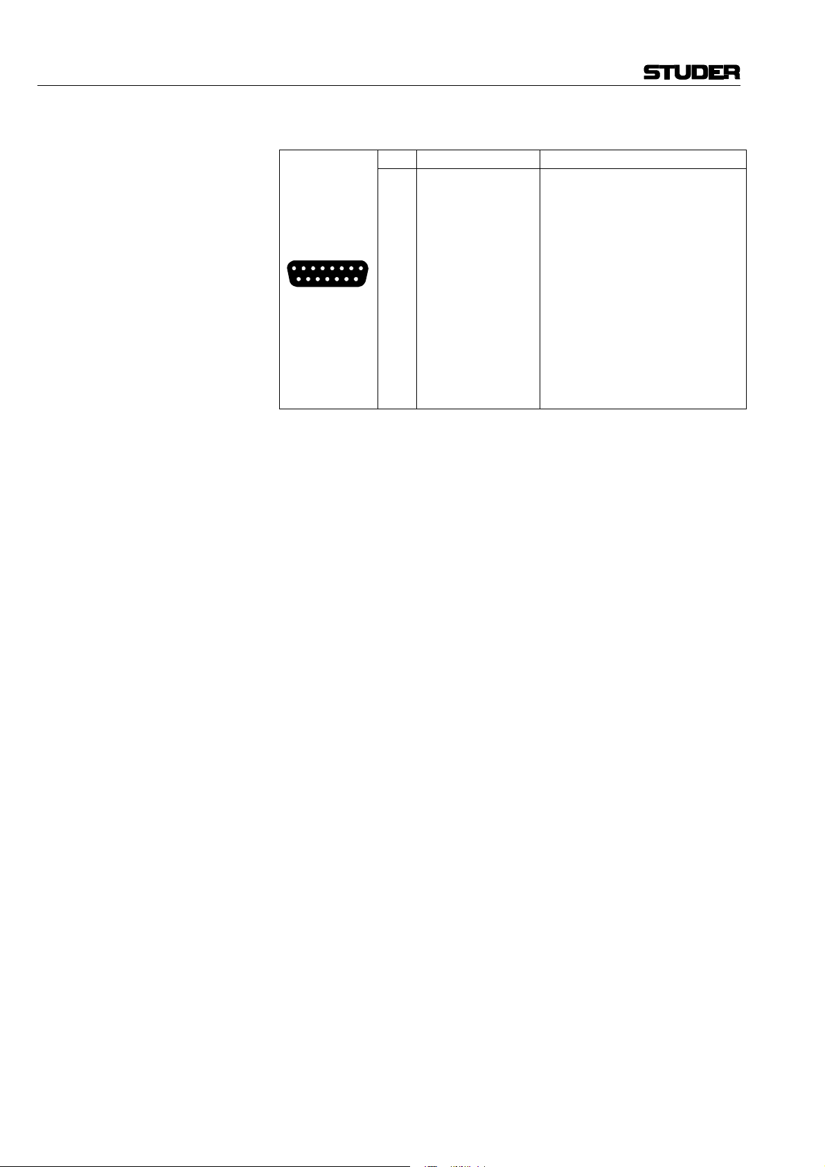
D424 MO Recorder
PARALLEL 15 pin D-type, female
Pin Signal Function
1
2
3
4
8 1
5
6
7
8
915
9
10
11
12
13
14
15
B_TAKE
B_INDEX
B_PLAY
S_STOP
S_PLAY
S_PLOC
FADER1
GND
B_STOP
B_READY
VCC
S_PREV
S_NEXT
FADER2
KEY
Take pulse
Index pulse
Play tally
Stop command
Play command
Ploc command
Fader start input 1
Ground
Stop tally
D424 ready
Supply voltage, switchable 5/24 V
Previous command
Next command
Fader start input 2
Key
E1/12 General SW V 1.6 Date printed: 19.10.01
Page 31

D424 MO Recorder
1.7 Technical Specifications (Subject to change as technological progress may warrant)
1.7.1 Drive System
The D424 is equipped with an ISO standard 2.6 or 5.2 GB drive supporting
the following 5¼" disk standards:
2 × WO 1.2 / 1.3 GB 512/1024 bytes/sector
4 × WO/DW 2.3 / 2.6 GB 512/1024 bytes/sector
8 × WO 4.1 / 4.8 / 5.2 GB 512/1024/2048 bytes/sector
(WO = Write Once; DW = Direct Overwrite)
The D424 also supports SCSI CD writers.
1.7.2 Recording Formats
• Linear recording mode with 16, 20 or 24 bit resolution
• Standard file system and audio files (MS-DOS and WAVE)
• Session data supports major manufacturer standard
1.7.3 Audio Processing
Switchable Word Length 16/20/24 bits
Sampling Rates 44.056, 44.1, 47.952, 48 kHz
Varispeed Operation ±12.5%
Digital Scrub Range 0...±2 V
nom
Real-time Output Gain Control (–∞...12 dB)
1.7.4 Audio Input/Output
Digital I/O AES-3, balanced, transformer coupled, XLR connector
Monitor Output (headphone connector)
• Unbalanced, 6.3 mm Jack connector
• 16 bit D/A converter
Impedance 100 Ω
Level Max. 7 V, with potentiometer volume control
Analog In (measured with line level of +15 dBu for 0 dBFS)
• Balanced, transformer coupled, XLR connector
• 20 bit delta-sigma converter (64 times oversampling)
Impedance >10 kΩ
Level 10...24 dBu (for 0 dBFS),
electronically adjustable in steps of 0.5 dB
Frequency Response 20 Hz...20 kHz ±0.1 dB
THD + N < –87 dBFS (20 Hz...20 kHz, 0 dBFS)
< –103 dBFS (1 kHz, –20 dBFS)
Channel Crosstalk > 110 dB (1 kHz)
Date printed: 19.10.01 SW V 1.6 General E1/13
Page 32

D424 MO Recorder
Analog Out (measured with line level of +15 dBu for 0 dBFS)
• Electronically balanced, XLR connector
• 20 bit delta-sigma converter (128 times oversampling)
Impedance < 30 Ω
Level 4 digitally selectable levels between 10...24 dBu (for 0 dBFS), adjustable
with trimmer potentiometer (default +10, 15, 20, 24 dBu)
Frequency Response 20 Hz...20 kHz ±0.1 dB
THD + N < –90 dBFS (20 Hz...20 kHz, –1 dBFS)
< –98 dBFS (1 kHz, –20 dBFS)
Channel Crosstalk > 110 dB (1 kHz)
De-Emphasis 50 ms/15 ms
1.7.5 Synchronization
AES-11 Input XLR connector
Word Clock Input BNC connector, with termination selector. Minimum level: 1 Vpp
Composite Video Input 2 BNC connectors, with termination selector
Word Clock Output BNC connector, TTL Level
1.7.6 Timecode
Accepts and generates all available formats:
24, 25, 29.97D and 30, 29.97 and 30D
(D = drop frame mode for NTSC compensation)
Reader For timecode recording and chase mode,
balanced, transformer coupled, XLR connector
Input Level 0.5...5 V
Speed Range 0.1...2 times nominal speed
Generator For providing LTC of current position,
balanced, transformer coupled, XLR connector
Nom. Output Level 2 V (peak to peak)
1.7.7 Control Interfaces
• Desktop Controller interface
For multi-machine configurations, providing sample-accurate synchronization between up to three D424 units (RS422, 15 pin D-type)
• System remote interface
With proprietary or SONY 9 pin protocol (RS422, 9 pin D-type)
• Parallel port
With basic commands, fader start and tallies (15 pin D-Type)
• SCSI-2 for external drives and data transfer
E1/14 General SW V 1.6 Date printed: 19.10.01
Page 33

1.7.8 Power Supply
Power Requirements 100...240 VAC ±10%, 50...60 Hz, 1.4...0.6 A
1.7.9 Operating Conditions
Ambient Temperature: +5...+35 °C
Rel. Humidity: 10...80%, non-condensing
Operating Position: horizontal ±10°
1.7.10 Standards
Safety Standard: Protection class 1, EN 60950; 1992 + A1/A2; 1993
Class 1 laser product, EN 60825-1; 1994
EMC Standard: EN 50081-1; 1992, EN 50082-1; 1992
D424 MO Recorder
1.7.11 Physical Dimensions
Size 438 × 142 × 392 mm (W × H × D); 19" rack-mount size, 3 HU
Weight 9.5 kg
Date printed: 19.10.01 SW V 1.6 General E1/15
Page 34

D424 MO Recorder
1.8 Syntax Used in this Manual
[COMMAND] Keyboard entries are indicated in bold printing and within [ ] brackets.
[PLAY] “PLAY” key.
[REC+PLAY] Double key combination: [REC] is pressed first and, as long as [REC] is
pressed, [PLAY] is pressed additionally.
[1...9] One of the keys [1] to [9].
[ENT or PLAY] Either the [ENT] or the [PLAY] key.
[SETUP] [3] [1] [6] [0] [ENT] [u] [6] [0] [ENT] [SETUP]
Sequence of keys pressed one after the other.
E1/16 General SW V 1.6 Date printed: 19.10.01
Page 35

2 OPERATING ELEMENTS
D424 MO Recorder
[1] [2] [3] [19] [18] [37]
[39] [41] [40] [27] [28] [29]
[42] [36]
[38]
[35]
[34]
D 424 MO RECORDER DISK RECORDER SERIES
POWER
LOC CHASE LOOP
PHONES
PREV NEXT PLAY STOP REC
[4] [15] [16] [17] [14]
ASS
INS
AUT
[10]
CUE
SHTL
PEAK RESET
[12]
OVER
0
–2
–5
–7
–10
–14
–20
–30
–40
–50
dB
INP 1 INP 2 INP TC
RDY 1 RDY TCRDY 2
TIME–FORMAT–TAKE
SETUP SEQ
CUT ERASE INSERT 8 9
SOURCE UNDO TARGET
PREVIEW IN OUT CAPT
[20] [25] [30] [26]
[33]
REG
TAKE
IND
CLR
7
4
5
1
2
0
+/-
[32][24][23][31][22][21][11][13][6][7][9][8][5]
[37] [38][43][18][19]
D424 REMOTE CONTROLLER
PEAK RESET
OVER
–2
–5
–7
–10
–14
–20
–30
–40
–50
dB
0
DISK RECORDER SERIES
SETUP
SEQ
[41]
[39a] [40a]
[42]
7
8
9
5
6
UNIT 1
INP 1 INP 2INP TC
[20]
FORMAT
TIME TAKE
[27] [28] [29] [34]
CUT
ERASE INSERT
REG
4
[43]
6
3
ENT
UNIT 2
RDY 1RDY TC RDY 2
[40b][39b]
SOURCE
UNDO TARGET
[21]
UNIT 3
[22]
VOLUME
PHONES
[4] [46] [17][16] [14]
[44] [32]
VOL 1 VOL 2
[45]
INST LOCK CHASE LOOP
PREV NEXT PLAY STOP REC
PREVIEW OUT CAPT
IN
[25] [30] [26]
[23][31]
ASS
INS
AUT
LOC
[33][24]
CUE
SHTL
[5] [8] [9] [7] [6] [13] [15] [10] [11]
[35]
TAKE
IND
[36]
[12]
1
2
3
0
+/–
ENT
CLR
SLOW
[47]
Date printed: 19.10.01 SW V 1.6 Operating Elements E2/1
Page 36

D424 MO Recorder
2.1 General (* = not available on Desktop Controller)
*[1] POWER Switches the D424 on or off.
*[2] Disk A disk is inserted by gently pushing it in until the loading mechanism en-
gages.
*[3] t I (Eject) A disk is ejected by pressing this button in stop mode.
[4] VOLUME A stereo headphone may be connected to the 6.3 mm jack socket [5], the
[5] PHONES volume is adjusted with potentiometer [4].
2.2 Transport Section
[6] STOP Stops the recorder at the current position.
During recording, a stop command terminates the session.
[7] PLAY Starts playing from the current position.
During insert recording, a play command performs a punch-out.
[8] PREV Skips to the previous take or index marker.
[9] NEXT Skips to the next take or index marker.
[10] CUE/SHTL The control wheel key [10] switches to CUE or SHTL (shuttle mode,
[11] Control Wheel starting with the one which was used last. Each subsequent keystroke
[12] Speed Indication LEDs toggles between speed control (SHTL) and position control (CUE). The
currently selected mode is indicated with the LEDs next to the CUE/SHTL
key.
The control wheel allows to modify speed or position, the current speed is
indicated with the speed indication LEDs.
[13] REC Recording is started by pressing [REC+PLAY] simultaneously; a record-
pause status is entered with the key combination [REC+STOP].
[14] ASS/INS/AUT (Rec. Mode) One of the available recording modes (ASSemble/INSert/AUTo) is pre-se-
lected by pressing the key [14] until the desired mode is indicated.
[15] LOC With this key and a subsequent destination (register, take/index number, or a
shortcut) the D424 can be set to a new position.
[16] CHASE In chase mode, the D424 is following the external timecode.
[17] LOOP In loop mode the D424 plays the element between the IN and OUT point
repeatedly.
[18] LED Level Meter Displays input or disk level, either in peak or in peak hold mode.
[19] PEAK RESET For resetting the meter display when in peak hold mode.
[20] INP 1, INP 2 Output source selection. Either the input signal (LED is on) or the informa-
tion from the disk (LED is off) is provided at the output channels.
E2/2 Operating Elements SW V 1.6 Date printed: 19.10.01
Page 37

D424 MO Recorder
[21] RDY 1, RDY 2 Record ready switch. The LED is flashing when the channel is set ready for
recording; it is on during recording.
[22] RDY TC, INP TC Timecode channel selectors.
2.3 Editing Section
[23] IN, IN and OUT are the edit registers. A source element is defined with the IN
[24] OUT and OUT registers, and the target point with the IN register (when in target
mode).
A register is selected with the corresponding keys [IN] or [OUT], modifications are possible either with [CAPT], the control wheel, or the numeric
keypad.
[25] SOURCE After selecting [SOURCE], all edit operations related to a source element
are enabled (cut, erase).
[26] TARGET After selecting [TARGET], the source element may be inserted at the target
point with [INSERT].
[27] CUT Cuts out the source element.
[28] ERASE Erases the contents of the source element.
[29] INSERT Inserts the source element at the position defined with the target IN point.
[30] UNDO The D424 reverts to the status before the last editing process.
[31] PREVIEW In editing modes (source or target LED on), [PREVIEW] followed by a
second key allows to preview either the edit points (with [IN] or [OUT]),
the selected element (with [SOURCE]), or an edit process (with [CUT],
[ERASE], or [INSERT]).
When not in edit mode, the [PREVIEW] key is used as rehearse mode selector and indication for insert recording.
2.4 Keyboard and Register Section
[32] 0...9, CLR, +/–, ENT Register and menu parameters can be set with the numeric keypad. Values
which were entered in the display buffer are stored to the register with the
[ENT] key. With [CLR] the display buffer is cleared.
[33] CAPT Copies the current position to the register selected with the numeric keypad.
[34] REG With this key and a subsequent register number (0...9), one of the available
registers is selected. It can be set and used for locating or editing.
[35] TAKE This key is used for directly addressing takes for locating, or for setting and
clearing take markers (in combination with [INSERT] and [ERASE]).
Date printed: 19.10.01 SW V 1.6 Operating Elements E2/3
Page 38

D424 MO Recorder
[36] IND This key is used for directly addressing index positions within takes when
locating, or for setting and clearing index markers (in combination with
[INSERT] and [ERASE]).
2.5 Display and Menu Section
[37] SETUP Pressing [SETUP] toggles between standard and SETUP mode, which is a
menu-structured display mode for setting the D424's configuration and parameters, and performing system utilities.
Submenus and items are selected with the cursor keys [39]...[42], the control wheel with [ENT], or directly with the numeric keys [1]...[8].
[38] SEQ With [SEQ] the sequence editing mode is entered. It allows defining and
editing sequences and deleting sound files (also refer to the Sequence editing
section).
[39] TIME FORMAT / t In standard mode, the current position may be switched between absolute,
relative, or timecode formats.
In setup and sequence editing modes the key is used as cursor key.
Note: On the Desktop Controller, these two functions have dedicated keys.
[40] TAKE FORMAT / u In standard mode, the current take number can be shown with or without
index markers. If index markers are indicated as well, all skip functions are
referring to both markers instead of take markers only.
In setup and sequence editing modes the key is used as cursor key.
Note: On the Desktop Controller, these two functions have dedicated keys.
[41] z, [42] i Cursor keys, used in setup and sequence editing modes.
[43] Display The display section consists of 4 lines with 20 digits each. Depending on the
selected mode, there are different configurations. The standard configuration
is:
Line 1: Graphical indication of the current position within the sequence
Line 2: Current take (and index) number, current position
Line 3: Sequence number, remaining time, or register entry field
Line 4: D424 configuration (sampling frequency, word length, input, clock source,
recording mode, emphasis).
2.6 Additional Functions (Desktop Controller only)
[44] UNIT 1...3 For assigning one of up to three D424 units to the Desktop Controller.
[45] VOL1, VOL2 For modifying the analog input attenuation for the two channels together
with the control wheel.
[46] INST LOCK Locks the unit immediately to a master timecode at the current position; the
current offset is stored to the nominal offset register. Chase mode is selected
automatically.
[47] SLOW Reduces the cue speed to one third of the standard cue speed.
E2/4 Operating Elements SW V 1.6 Date printed: 19.10.01
Page 39

3 GETTING STARTED QUICKLY
3.1 Recording New Takes From an Analog Source
3.1.1 Installation and Settings
1. Connect the analog outputs of the source unit to the analog input connectors
of the D424 (LINE IN 1/2) with XLR cables.
2. Insert a write-enabled disk with sufficient free recording space (see step 7).
3. Check the status of the D424 in the fourth display line. There, sampling
rate, recording format, clock reference, audio input, and recording mode are
indicated.
The standard setting is: 441, 16, INT, ANA, ST.
If necessary, change the settings for sampling rate, recording format, and
recording mode. The clock reference may also be external.
Note: There is only one sampling rate allowed per disk side. Changing the fre-
quency is only possible with an empty disk.
D424 MO Recorder
4. Recording mode should be set to ASS (LED above the REC button), which
5. Check the input levels by switching the D424 to input with [INP1] and
Example: Set the input attenuation of both channels to –6 dB:
3.1.2 Start Recording
6. Set the recording channels to READY by pressing [RDY1] and [RDY2]
7. Check the remaining recording time with [REC+STOP]. The remaining
8. Start recording with [REC+PLAY].
9. It is possible to set the take and the index markers on-the-fly with
10. Stop the recording session with [STOP].
is the default setting after switching on the D424.
[INP2].
Apply the input signals and check that there is no overload (red LED) at the
loudest position. The input signal attenuation may be adjusted in the setup
menu 31.
[SETUP] [3] [1] [6] [0] [ENT] [u] [6] [0] [ENT] [SETUP]
(both corresponding LEDs will be on).
time is indicated in the display.
[TAKE+INSERT] or [IND+INSERT].
Date printed: 19.10.01 SW V 1.6 Quick Start Guide E3/1
Page 40

D424 MO Recorder
3.2 Recording New Takes From a Digital Source
3.2.1 Installation and Settings
1. Connect the AES/EBU output of the source unit to the AES/EBU input
connector of the D424 (AES/EBU IN) with an XLR cable.
2. Insert a write-enabled disk with sufficient free recording space (see step 6).
3. Check the status of the D424 in the forth line of the display. It indicates
sampling rate, recording format, clock reference, audio input and recording
mode.
The standard setting is: 441, 16, INT, ANA, ST.
If necessary, change the settings for sampling rate, recording format, and
recording mode.
Switch the input to AES/EBU with:
[SETUP] [2] [1],
select “dig” with: [u] [ENT] [z] [u] [i],
select “audio” with: [u] [ENT] [SETUP] .
Notes: There is only one sampling rate allowed per disk side. Changing the fre-
4. The recording mode should be set to ASS (LED above the REC button),
3.2.2 Start Recording
5. Set the recording channels to READY by pressing [RDY1] and [RDY2]
6. It is now possible to check the remaining time with [REC+STOP]. The
7. Start recording with [REC+PLAY].
8. It is possible to set the take and the index markers on-the-fly with
9. Stop the recording session with [STOP].
quency is only possible with an empty disk.
An error message will appear when the D424 settings do not match with the
source signals.
which is the default setting after switching on the D424.
(both corresponding LEDs will be on).
remaining recording time is indicated in the display.
[TAKE+INSERT] or [IND+INSERT].
E3/2 Quick Start Guide SW V 1.6 Date printed: 19.10.01
Page 41

3.3 Playing Pre-Recorded Disks
3.3.1 Installation and Settings
• Check that the D424 is either set to internal reference, or the corresponding
external reference clock has to be provided. With an external clock, the DIG
indication in the bottom line of the display must not flash:
441, 16, INT, DIG, ST.
• Be sure that the INP switches are not activated.
• Insert a disk and wait until the sequence data have been loaded from disk.
3.3.2 Position
Take and index numbers as well as the current position are shown in the
display. The position indication may be adapted with the following keys:
[TIME] switches between absolute time (a: sequence time, starting with 0), relative
time (r: take time, time within take) or timecode position (t). If no timecode
was recorded, the timecode display is identical with the absolute time indication, the “t” mark is flashing.
[TAKE] switches between take display, or take and index display.
D424 MO Recorder
3.3.3 PLAY and STOP
Start playing with [PLAY], stop at the current position with [STOP].
3.3.4 Skip to Take and Index Markers
With [PREV] and [NEXT], the D424 will locate or continue playing at the
next or previous marker. Depending on the selected TAKE mode, only take
markers or take and index markers are considered.
Example: When playing take 5 and pressing [NEXT] twice, the D424 will continue
playing at the beginning of take 7.
Use the LOCATE function to access markers directly.
3.3.5 CUE and SHUTTLE
With [CUE], either the CUE or SHUTTLE mode is selected. Subsequent
keystrokes toggle between the two modes.
In CUE mode, the D424 follows the control wheel position with a speed up
to 2 times nominal speed. In SHUTTLE mode, the D424 moves with a constant speed, which is set with the control wheel.
Date printed: 19.10.01 SW V 1.6 Quick Start Guide E3/3
Page 42

D424 MO Recorder
3.3.6 LOCATE
Find a particular position in a sequence with the locate function. Locating is
available to sequence, take, and index positions as well as to register locations having been set in advance.
Examples:
[LOC] [PREV] – locate to begin of sequence
[LOC] [NEXT] – locate to end of sequence
[LOC] [2] [STOP] – stop at take 2
[LOC] [2] [PLAY] – play from take 2
[LOC] [2] [ENT] – locate to take 2
[LOC] [2] [IND] [3] [PLAY] – play from take 2 index 3
[LOC] [IN] – locate to IN register
[LOC] [REG] [3] – locate to register 3.
When not terminated with [STOP] or [PLAY], the recorder will continue in
the same status as it was before (stop or play).
3.3.7 Setting Markers
Notes: Newly inserted take markers will get the first available free number, and will
Set and remove markers with the following keystrokes:
[TAKE+INSERT] – inserts a new take marker
[INDEX+INSERT] – inserts a new index marker
[TAKE+ERASE] – removes the take marker which is currently displayed
[INDEX+ERASE] – removes the index marker which is currently dis-
played.
Moving a marker is achieved by removing it at the old position and inserting
it at the new place.
keep it during further editing.
When moving a take marker with [ERASE] followed by [INSERT], it will
keep its number.
Index numbers are always contiguous within a take. After inserting or removing index markers, they will be renumbered automatically.
E3/4 Quick Start Guide SW V 1.6 Date printed: 19.10.01
Page 43

3.4 Editing
3.4.1 Before You Start Editing
• Verify that there is a write-enabled disk inserted.
• The sequence currently selected will be modified. If you have already edited
a part of the sequence and you would like to keep the current version, start
editing with a copy of the sequence.
• The current setting of the cross-fade time (setup menu item 34) will be used
by all editing processes. Change them if necessary.
3.4.2 Cut Out or Erase an Element – Cut/Erase Editing
For cutting out or erasing an element of the current sequence:
• Define a source element by setting the edit registers [IN] and [OUT], and
perform an [INSERT] command.
With larger productions, it is helpful to mark the points to be edited in advance. For this purpose, set index markers either during the recording or
when pre-listening the material.
1. Switch on the source editing mode with [SOURCE].
2. Find the element to be removed and copy the start point of the element to the
IN register, the end point to the OUT register. There are different ways:
• Listen to the sequence and mark begin and end of the element with
[IN] [CAPT] [OUT] [CAPT], or
• locate to the points when there are already markers and change to CUE
for precise positioning. Transfer the current address to the register with
[IN] [CAPT], or [OUT] [CAPT], or
• search the point with the control wheel in SHTL mode (adjust the maxi-
mum wind speed in the setup menu 41, if necessary), slow down and
change to CUE for precise positioning. Transfer the current address to
the register with
[IN] [CAPT] or [OUT] [CAPT].
3. Check the settings with the REHEARSE feature. De-select the edit registers
and choose one of the following rehearse commands:
[PREVIEW] [IN] – listen to the section before the IN point
[PREVIEW] [OUT] – listen to the section after the OUT point
[PREVIEW] [SOURCE] – listen to the selected element between IN and
OUT
[PREVIEW] [CUT] – rehearse the cut command
[PREVIEW] [ERASE] – rehearse the erase command.
4. Modify the edit points if necessary and check again (item 3).
You can either locate to the edit point and adjust it:
[LOC] [IN] [CUE]...[IN] [CAPT], or
Trim the edit register directly with the cursor keys: [IN] [i] [z].
Use the [SOURCE] and [TARGET] keys for accessing either the source
registers IN and OUT, or the target register IN.
5. If the settings are correct, the final cut or erase command is [CUT] or
[ERASE].
D424 MO Recorder
If the result of the command is not what you expected it to be, or if a wrong
edit command was executed by accident, it can be made undone with
[UNDO].
Date printed: 19.10.01 SW V 1.6 Quick Start Guide E3/5
Page 44

D424 MO Recorder
3.4.3 Move or Duplicate an Element – Insert Editing
For moving or duplicating an element of the current sequence:
• define a source element which should be moved or duplicated, by setting
the edit registers SOURCE IN and OUT,
• set the target location (i.e., where the source element should be inserted)
by setting the edit register TARGET IN,
• and perform an INSERT command.
With larger productions, it is helpful to mark the points to be edited in advance. For this purpose, set index markers either during the recording or
when pre-listening the material.
1. Activate the source editing mode with [SOURCE].
2. Find the element to be removed, copy the start point of the element to the
source IN register, and the end point to the source OUT register. There are
different ways:
• Listen to the sequence and mark begin and end of the element with
[IN] [CAPT] [OUT] [CAPT], or
• locate to the points if there are already markers, and change to CUE for
precise positioning. Transfer the current address to the register with [IN]
[CAPT] or [OUT] [CAPT], or
• search the point with SHUTTLE (adjust the maximum wind speed in the
setup menu 41, if necessary), slow down, and change to CUE for precise
positioning. Transfer the current address to the register with
[IN] [CAPT] or [OUT] [CAPT].
3. Activate the target editing mode with [TARGET].
4. Find the location to insert the source element defined above. Use one of the
methods described in item 2, and copy the position to the TARGET IN point
with [IN] [CAPT].
5. Check the settings with the REHEARSE feature. De-select the edit registers
and choose one of the following rehearse commands:
[PREVIEW] [IN] – listen to the section before the insert point,
[PREVIEW] [OUT] – listen to the section after the insert point,
[PREVIEW] [INSERT] – rehearse the insert command.
For adjusting the source element, simply switch to source editing mode with
[SOURCE] and use the corresponding preview commands ([IN] [OUT]
[SOURCE]).
6. Modify the edit points if necessary and check again (item 3).
You can either locate to the edit point and adjust it:
[LOC] [IN] [CUE]...[IN] [CAPT],
or
trim the edit register directly with the cursor keys: [IN] [i] [z].
Use the [SOURCE] and [TARGET] keys for accessing either the source
registers IN and OUT, or the target register IN.
7. If the settings are correct, the final insert command is [INSERT].
Repeat from step 3 if you like to insert the source element to different locations.
Moving an element is achieved by copying it to the destination first and then
cutting out the original source element. Simply press [CUT] after the last
[INSERT] command.
If the result of the command is not what you expected it to be, or if a wrong
edit command was executed by accident, the last command can be made undone with [UNDO] (single level undo).
E3/6 Quick Start Guide SW V 1.6 Date printed: 19.10.01
Page 45

3.5 Insert Recording
Use insert recording for directly replacing a part of the current sequence in a
“destructive way”. A typical example is dialog replacement.
3.5.1 Before You Start Recording
• Check your system configuration (refer to the analog or digital recording
sections).
• With a correct setup, no LEDs should be flashing. After switching to input
with the INP keys, you can monitor your source signal.
• You can check the free space available for recording with [RDY]
[REC+STOP]. Press [STOP] again to revert to standby.
3.5.2 Manual Insert Recording
D424 MO Recorder
1. Select the INSERT recording mode with the recording mode key (above the
STOP key). The “INS” LED will be on.
2. Set the recording channels to READY by pressing [RDY1] [RDY2] (the
corresponding LEDs will be on).
3. Start playing ahead of the section to be replaced, wait until the correct posi-
tion is reached, and then make record punch-in with a [REC+PLAY] command, or
park the D424 at the punch-in location and start recording with
[REC+PLAY].
4. Perform a punch-out with [PLAY] or [STOP].
Note: After having tried replacing a section for several times, all these attempts
will be stored on the disk. They can be made accessible when creating a new
sequence from the complete table of contents.
3.5.3 Auto Insert Recording
1. Select the AUTO recording mode with the recording mode key (above the
STOP key). The “AUT” LED will be on.
2. Store the beginning and the end of the section to be replaced to the edit registers; IN: punch-in point, OUT: punch-out point.
3. Set the recording channels to READY by pressing [RDY1] and [RDY2]
(the corresponding LEDs will be on).
4. Use the [PREVIEW] key to either perform a rehearsal (PREVIEW LED is
on) or a recording (PREVIEW LED is off).
5. Start with [REC+PLAY].
The D424 will start at IN-PREROLL, automatically perform a punch-in at
the IN point and a punch-out at the OUT point. It will stop at
OUT+POSTROLL.
During the process, the current mode as well as a countdown to the following event are indicated.
Date printed: 19.10.01 SW V 1.6 Quick Start Guide E3/7
Page 46

D424 MO Recorder
3.6 Working with Sequences
There may be several sequences on a disk. Only one of them can be selected
as the current sequence.
All modifications resulting from editing or sequence processing only change
the sequence data, which are kept with each sequence. They do not modify
or delete the audio information.
The [SEQ] key gives access to a number of features, which allow to:
• switch between the available sequences on a disk,
• create new, empty sequences,
• modify sequences by inserting or deleting single takes,
• delete complete sequences, or
• copy existing sequences.
3.6.1 Change the Current Sequence
If there is a sequence no. 2 available on the disk, it is selected with [SEQ]
[2] [ENT].
3.6.2 Create a New Sequence
A new, empty sequence is created with [SEQ] [ENT].
If it is necessary to assign a specific number to the new sequence, the new
number is added to the command. If there are 3 sequences on a disk, and the
following numbers should be reserved for additional revisions, a new sequence no. 10 is created with [SEQ] [10] [ENT].
3.6.3 Modify a Sequence
When modifying a sequence, single takes can be added or deleted.
Entering sequence editing mode: For entering the sequence editing mode, the following parameters are neces-
sary:
• a source sequence number (i.e. the number of the sequence where the
takes are to be copied from).
• a target sequence number (i.e. the sequence to be modified), and
[SEQ] [n] [SOURCE] – modify sequence “n”; the default source sequence is the table of contents of the disk.
[SEQ] [n] [u] [s] [SOURCE] – modify sequence “n”, with source
sequence “s”.
In editing mode, both source and target sequences are displayed. After having selected one of them with the [SOURCE] or the [TARGET] key, the
take positions can be entered for executing the functions “add additional
takes”, and “delete takes” described below.
E3/8 Quick Start Guide SW V 1.6 Date printed: 19.10.01
Page 47

Adding additional takes: Select the take to be copied from the source sequence, and the insert position
Deleting takes: Specify the target take to be deleted:
3.6.4 Copy a Sequence
D424 MO Recorder
in the target sequence:
[3] [TARGET] [5] [INSERT] – Insert take 3 from the source sequence,
after take 5;
[INSERT] [INSERT], ... – further INSERT commands will copy takes 4,
5, and so on.
[TARGET] [4] [CUT] – delete take 4 from the target sequence;
[CUT] [CUT], ... – further CUT commands will delete take 3, 2, and so
on.
For copying an existing sequence, enter editing mode and perform a
TARGET+INSERT command:
[SEQ] [u] [2] [SOURCE] [TARGET+INSERT] – create a new se-
quence as a copy of sequence 2.
Note: If the [TARGET+INSERT] command is applied to a non-empty sequence,
3.6.5 Delete a Sequence
the current data are overwritten by the copied sequence data.
For deleting a sequence, enter the editing mode and perform a
[TARGET+CUT] command:
[SEQ] [2] [SOURCE] [TARGET+CUT] – delete sequence 2.
Date printed: 19.10.01 SW V 1.6 Quick Start Guide E3/9
Page 48

D424 MO Recorder
3.7 CD Transfer and Disk Copies
For making transfers and backup copies between the D424 and external
drives such as further MO disk drives or CD writers, establish a SCSI connection between the two devices.
3.7.1 Before You Start the Transfer
• Switch the two units off and connect the SCSI cable.
• Make sure that the two units have not the same SCSI address. The default
address of a D424 is “1”, the one of the Studer D741 is “2”. Refer to the
corresponding section in the operating manual of the device for changing
SCSI addresses.
• Switch on the peripheral device first, and switch it to SCSI mode (Studer
D741: SCSI ON, D424: SCSI offline mode).
• Switch on the D424.
3.7.2 Creating a CD with an External SCSI CD Writer (e.g. Studer D741)
When making a master copy of the current D424 sequence to an external
CD writer, the audio information including all track and index markers will
be transferred to the CD. Furthermore, PQ information like ISRC and UPC
codes can be added.
Note: Only sequences recorded with 44.1 kHz sampling rate can be directly trans-
ferred to the CD recorder.
• Insert a CD-R. Use an empty disc if you intend to burn a CD in a disc-atonce operation.
Entering UPC and ISRC Codes Select the UPC menu 642, enter the UPC code, and confirm with [ENT].
An UPC code will be accepted only if no UPC code has been programmed
yet.
Select the ISRC menu 643 and enter a code for each track. Set the sequence
to the first track and enter the code for track 1. For skipping the track number, use the [NEXT] key, and update the display with [z] [i].
Note: The first group of the ISRC code requires alphanumeric entries. Start with
the [i] key, select the digit with the control wheel and go on to the next
digit with the [u] key.
Set the CD Transfer Parameters Use the standard setting for transferring a 16 bit sequence to a new, empty
CD. No additional processing is done (no noise shaping, no additional
pauses will be inserted). Refer to “Operation”, section 4, for details.
Start the Transfer Select the master copy menu 62. If the “CD mounted” message is not visi-
ble, the CD writer has to be selected as target drive first:
• Select the “target” submenu and select the CD drive as target drive (use the
[t] or [u] keys to locate one of the items, the [i] key to select items or to
enter submenus, or the [z] key to return to the previous menu).
• Start the transfer process by moving to the “start” item and confirming with
[ENT].
During the whole process, a progress bar is revealed. After a successful
transfer, the disc will be finalized. Usually, the CD writer (e.g. Studer
D741) will open its disc tray.
E3/10 Quick Start Guide SW V 1.6 Date printed: 19.10.01
Page 49

3.7.3 Copying a CD to the D424
The contents of a CD can be copied to a new sequence on the D424 disk,
including all track and index markers.
• Check the inserted disk: it should not be write protected, have sufficient free
capacity for adding the CD information, and the format must be CD compatible (44.1 kHz sampling rate).
• Select the CD writer as the current source drive. Use the setup menu 51 for
this purpose; the CD drive usually has the SCSI address 2.
• If the copy mode in menu 644 is set to “toc”, the complete CD will be
transferred; if it is set to “add”, only the currently selected track will be
copied.
Use the D424 transport keys for pre-listening and selecting CD tracks.
• Select the master copy menu 62 and enter the “target” submenu to select the
MO disk as target drive, the internal SCSI address is usually 1 (use the [t]
or [u] keys to locate one of the items, the [i] key to select items or to enter
submenus, or the [z] key to return to the previous menu).
• Start the transfer process by moving to the “start” item and confirming with
[ENT].
During the whole process, a progress bar is revealed. After a successful
transfer, the display reverts to standard mode.
D424 MO Recorder
3.7.4 Copying to/from Other MO Disks
Sequences and complete disks can be copied from the internal drive to additional external drives. There are 3 possible choices:
DISK COPY will copy the complete disk. The target disk has to be empty. Reformat it
before, if necessary (setup utility 53).
MASTER COPY will create a new sequence on the target disk as an exact copy of the source
sequence, including track and index information. The audio information will
be merged into a new single sound file.
WORK COPY will create a new sequence on the target disk. It is identical with the source,
and includes all sequence information. All sound files used by the sequence
will be transferred as well.
• Check the target disk. It must not be write protected, have enough free capacity for adding the source information, and the sampling rate of both disks
must be identical.
• Use the setup menu 51 to check if:
the internal drive is currently selected as the active one, and
the external drive appears on the drive list.
• Go to one of the copy menus (Work Copy 61, Master Copy 62, Disk Copy
63) and check the indicated transfer information “copying sequence/track i
to drive m”)
• Modify the target address if necessary (submenu target).
• Start the transfer process by moving to the “start” item and confirming with
[ENT].
During the whole process, a progress bar is revealed. After a successful
transfer, the display reverts to standard mode.
Date printed: 19.10.01 SW V 1.6 Quick Start Guide E3/11
Page 50

D424 MO Recorder
3.8 Working with Timecode
The D424 provides an LTC timecode input, which allows to record LTC
timecode. When playing back a sequence consisting of takes with different
timecode positions, the D424 will provide a contiguous timecode defined by
the first take.
3.8.1 Recording Timecode
• Check for correct timecode wiring by selecting [INP TC]. The incoming
code should be displayed.
• When recording timecode, be sure that the timecode source and the D424
are running synchronously. The usual way is to provide a common video
reference signal.
• Enable timecode recording with [TC RDY]. When the corresponding LED
is on, the timecode position will be added to the audio information of all
subsequent recording sessions.
Notes: The timecode information will be recorded as a single TC stamp at the be-
ginning of an audio file. Timecode jumps during recording will not be considered.
Timecode can be recorded only together with audio channel(s) set to
ready.
3.8.2 Playing Back Timecode
The D424 always provides the current position at the TC output connector.
If no timecode was recorded, the absolute position is present. During STOP
or CUE, a stationary code is generated.
3.8.3 Chasing to Timecode
In chase mode, the recorder is following an external timecode.
• When chasing to a master timecode, make sure that the master and the D424
are running with the same reference clock. Both master and D424 must be
configured to the same timecode format.
• Start/stop the chase mode with [CHASE].
Chase LED is On: Chase mode is on, D424 runs synchronously in PLAY mode.
Chase LED is Flashing: Chase mode is on, but D424 waits because the master is not in PLAY mode
(STOP or fast forward/rewind).
• An offset can be applied by storing a value (±12 hours) into the nominal
offset register. It is accessed with [REG] [0].
• An “instant lock” command will lock the D424 at the current position by
storing the current offset to the nominal offset register and launching the
chase mode. The command is performed with [LOC+CHASE] or with the
[INST LOCK] key of the desktop controller.
E3/12 Quick Start Guide SW V 1.6 Date printed: 19.10.01
Page 51

3.9 The Desktop Controller
The Desktop Controller may be used to control up to 3 recorders with an
ergonomic user interface.
3.9.1 Installation and Settings
1. Use the controller cable to connect the desktop controller to one of the two
controller ports at the rear side of the D424. Connect further units with
separate sync cables. The second connector of the last recorder must be terminated (termination plug).
D424 MO Recorder
D424 D424 D424
Desktop
Controller
2. Check the addresses of the connected units in setup menu 15. Each D424
should have a unique address.
3.9.2 Operation Enhancements
Desktop controller operation of a D424 is the same as front panel operation,
except for the following enhancements:
1. The controller is activated by selecting one of the connected units, using the
keys [UNIT1], [UNIT2], or [UNIT 3]. The D424 will indicate remote operation by a message in its local display. Press an other [UNIT ...] key (or
the active one again) for de-selecting the recorder being active.
2. Setting the input attenuation of the analog input signal is easier. Instead of
selecting the menu item 31, simply hold down the [VOL1] or [VOL2] key
and modify the level with the control wheel.
3. There are two different resolutions for the CUE mode. With the [SLOW]
key, the CUE speed is one third of the standard speed for more precise locating.
4. The mode keys for switching the take/index format and the time format are
now separated ([t] and [u] at the front panel).
5. The [LOC] key is closer to the destination keys ([IN] [OUT] [0...9]) and
it has the same size as the other main transport keys.
6. To the left of the [CHASE] key, there is a separate key for the [INSTANT
LOCK] function.
Termination
Sync cable Sync cableController cable
plug
Date printed: 19.10.01 SW V 1.6 Quick Start Guide E3/13
Page 52

D424 MO Recorder
3.10 The Parallel Port with Fader Start Operation
A parallel remote port is provided for basic transport control and status
indication, a fader start circuit, and supply voltages for external circuits.
3.10.1 Signal List
Inputs
4 S_STOP Generates a Stop command
5 S_PLAY Generates a Play command
6 S_PLOC Generates a Locate command to the last Play position (PlayLoc)
12 S_PREV Generates a Previous command, skip to the previous take/index
13 S_NEXT Generates a Next command, skip to the next take/index
7 FADER1
14 FADER2
Outputs
1 B_TAKE Take pulse, when passing a take marker in Play
2 B_INDEX Index pulse, when passing an index marker in Play
9 B–STOP Stop tally
3 B_PLAY Play tally
10 B–READY Ready for fader start operation
Others
8 GND Signal ground
11 VCC Supply voltage (5 or 24 VDC)
15 KEY
Fader start contacts
3.10.2 Fader Start
The D424 provides an opto-coupler input (with internal bridge rectifier and
20 mA current sink) for fader start operation. Use either an external voltage
source of 5...24 VDC, or use the internal supply voltage. The polarity of the
external supply voltage is of no importance.
D424
FAD1
FAD2
D424
FAD1
FAD2
GND
VCC
D424
FAD1
FAD2
GND
VCC
• Enable fader start operation with setup menu 45.
• When applying a control voltage at the fader input pins, the D424 will start,
releasing the control signal will result in a STOP.
Note: During fader play operation, the local keyboard is disabled.
E3/14 Quick Start Guide SW V 1.6 Date printed: 19.10.01
Page 53

3.11 The Setup Menu
D424 MO Recorder
The [SETUP] command is used for entering the setup mode, in order to
change parameters and to perform a number of utilities.
Navigation within a menu is done numerically or with the cursor keys:
[SETUP] [3] [1] – opens setup menu 31;
[t] and [u] – move to an item within a setup level (or control wheel);
[z] and [i] – go to the previous/next level or activate an item. [ENT] is an
alternative to [i].
For more detailed information on the setup menu see chapter 4.10 .
Menu Item Display Meaning Parameters
1 CONFIG System configuration
11 S.FREQ Sampling frequency 44.056, 44.1, 47.952, 48 kHz
12 S.WORD Sample resolution 16, 20, 24, 24L bits
13 TC Timecode format 24, 25, 29.97DF, 30, NONSTD
14 RECMODE Record mode stereo, mono
15 UNIT Unit selection unit1, unit2, unit3
16 DEFAULT Configuration
161 RECALL Recall User, PowerOn, Factory
162 STORE Save curr. config to user setting cancel, yes
17 REMOTE Remote local, remote
2 REF & INP Reference & input parameters
21 CLK SRC Ref. clock source int, dig, video
22 DIG REF Digital reference sync, wclock, audio
23 INPUT Audio input dig, analog, option
3 AUDIO Audio parameters
31 INP LEV Analog input attenuator inp1, inp2 (0...–14 dB)
32 OUT LEV Analog output level level (0...3)
33 DIG LEV Digital playback level channel1, channel2, (–12..+6 dB)
34 XFADE Crossfade time (0...2000) ms
35 METER Meter mode peak, peak hold
4 TRANSPORT Transport & display parameters
41 MAXSPD Maximum wind speed (2...30) × nominal speed
42 VARISPD Play varispeed off, on (±12.5%)
43 AUTO Auto stop off, on
44 PRE/POST Preroll/postroll (2...40) s
45 FADER Fader start1 disabled, enabled
46 REMAIN Remaining time mode auto, ind, take, seq
47 DISP RES Display resolution frames, ms
5 DISK Disk & sequence utilities
51 SELECT Select disk drive (1...6)
52 SCSI SCSI offline yes, no
53 FORMAT Format disk # ? cancel, yes
54 CLEANUP Cleanup disk # ? cancel, yes
55 REN-SEQ Renumber sequence ## ) cancel, yes
56 CLR-IND Clear all indices of sequence cancel, yes
57 DEL-FILE Delete sound file DESTRUCTIVE Seq #, take #; cancel, yes
6 COPY Copy utilities
61 WORK Work copy seq ## to drv # target, start
62 MASTER Master copy seq ## to drv # target, start
63 DISK Copy disk # to drv # target, start
64 XFER PAR Transfer parameters
641 SHAPING Noise shaping off, on
642 UPC/EAN UPC/EAN code 1234 1234 12345
643 ISRC ISRC code, track ## abcde 1234567
644 CD MODE CD copy mode toc, multi, add, fix
645 DELAY CD track delay off, on
646 INDEX 0 Index 0 duration off, on (2...5) s
65 FIXUP Fixup disk # ? (for SADiE exchg.) cancel, yes
7 SERVICE Service utilities
71 FORMAT Format disk # ? (up to 40 min!) cancel, yes
72 DATE Date & time day.month year hours:min
Date printed: 19.10.01 SW V 1.6 Quick Start Guide E3/15
Page 54

D424 MO Recorder
E3/16 Quick Start Guide SW V 1.6 Date printed: 19.10.01
Page 55

4 OPERATION
4.1 System Configuration
There is a number of configuration parameters in the D424 that are stored
either in a battery-buffered RAM or on the disk. The default values of the
D424 have been chosen for easy and safe operation.
After switching on the D424 for the first time, or after restoring the factory
default values, the D424 is ready to be operated and to record from analog
sources.
4.1.1 Recording Formats
Before starting a new recording session, check the current status in the display.
D424 MO Recorder
The parameters can be modified in the following setup menus:
• Menu 11: Sampling rate
• Menu 12: Sample word length
• Menu 14: Recording mode
Notes: It is possible to have different recording modes and sample word lengths in a
single sequence. There are no restrictions in editing and transferring.
However, only one sampling frequency is allowed per disk side. An error
message will appear if the sampling frequency does not match with the format already existing on the disk.
The emphasis status a digital recording is stored to the disk together with the
audio information. The status of the first take determines the status of a sequence. A warning will be displayed if subsequent recordings do not match
with the emphasis status of the current sequence.
Date printed: 19.10.01 SW V 1.6 Operation 4/1
Page 56

D424 MO Recorder
4.1.2 Audio Input
The input source is selected with the setup menu 23. Select “dig” for recording digital signals connected to the AES/EBU input, or “analog” for recording analog line signals at the LINE IN connectors.
Notes: The D424 ha s to be equipped with the analog I/O option for analog recor d-
ing and playback.
Check the correct synchronization of digital sources and the D424 if recording digital audio. Both the source machine and the D424 have to be
locked to the same reference (see the following section).
4.1.3 Reference Clock Source
The currently selected clock source is also shown in the display status line.
In case of an external reference, the presence of a correct signal is indicated
by a non-flashing clock source indication (INT, VID or DIG).
Selecting the Correct Reference There are the following settings for the D424 clock synchronization:
Mode Setup menu 21 Setup menu 22 Reference input
Internal int - -
Video video - VIDEO
Digital, AES-11 ref. dig sync AES/EBU SYNC
Digital, AES-3 audio input dig audio AES/EBU IN
Digital, word clock dig wclock WORDCKLOCK IN
• If the D424 is used in a analog environment, select the Internal Mode.
• If one or few digital machines are connected for playback or recording, and
the peripherals can be locked to one of the D424's sync signals (Word Clock
or Digital Audio) select the Internal Mode.
• If the other machines do not accept the D424's sync signals, connect one of
the peripheral's sync signal to the D424, and select the corresponding Digital
Mode.
Note: Be sure that the master machine is always switched on when operating the
D424, and that it provides the reference signal in all conditions.
E4/2 Operation SW V 1.6 Date printed: 19.10.01
Page 57

• If the D424 is integrated into a system with video and digital audio equip-
• If a common high quality reference is available in a digital environment, use
4.1.4 Other Parameters
• remote operation
• storing user defaults
• timecode and display formats
• audio levels and editing parameters
• transport parameters.
D424 MO Recorder
ment, use a stable composite video reference as master for all machines.
Switch the D424 to Video Mode.
the corresponding Digital Mode. AES-11 and Word Clock are preferred.
There is a number of general parameters for
They are accessible in the setup menu. Refer to the corresponding manual
section for more details, or find a complete list of parameters and utilities in
the setup menu section.
Date printed: 19.10.01 SW V 1.6 Operation 4/3
Page 58

D424 MO Recorder
4.2 Display and Register Functions
4.2.1 Display Information and Formats
The standard display shows various information on 4 lines.
Line 1 • The position indicator at the top of the display is indicating the current pos i-
tion, relative to the selected sequence. It allows to see roughly where the re corder is, when controlling it with the transport commands.
Line 2 • The current take and index.
Use the [TAKE] key to display either the take only, or take and indices.
• The selected time mode.
Use the [TIME] key to display the current time in one of the following formats:
“a” Absolute time
“r” Relative time to take begin or last index marker
“t” Timecode.
• The current time.
The time field is showing the current position in hours, minutes, seconds and
frames or milliseconds. Select either frames or milliseconds as display
resolution with setup menu 47.
Line 3 • The currently selected sequence
• Following the “rem” indication, the field at the right shows the remaining
time to one of the following points. Use setup item 46 to select:
- the next take or index marker, depending on the take format
- the next index marker
- the next take marker
- the end of the sequence.
The third line is also used for displaying alternative information. Depending
on the current mode, the following information may appear instead of the
remaining time:
“free” free recording time (during recording modes)
“to in”, “to out” countdown to IN or OUT point (during preview, auto record)
“var” current play varispeed (during varispeed operation)
“reg0”...“reg9” entry field for general purpose register (register editing)
“in”, “out” entry field for edit registers IN, OUT (register editing)
E4/4 Operation SW V 1.6 Date printed: 19.10.01
Page 59

D424 MO Recorder
Line 4 The bottom line indicates the status of the main configuration and the cur-
rent take parameters:
Sampling Rate 44D 441 48D 48
Sampling frequencies include 44.1 kHz (441), 48 kHz (48) as well as the
drop-frame formats 44.056 kHz (44D) and 47.952 kHz (48D).
Word Length 16 20 24
Word length allows 16, 20, and 24 bit recording.
Audio Input AES ANA (OPT)
Audio inputs are AES/EBU (AES), Analog (ANA) or further optional I/Os
(OPT). With an appropriate adapter, the AES input will also accept SPDIF
signals.
Clock Source INT VID DIG
The following clock sources may be selected: Internal (INT), video (VID),
and digital input (DIG). For detailed information see the System Configuration section.
Channel Configuration ST MON
Files are either recorded in stereo (ST) or mono (MON) mode.
Emphasis E
Digital signals with emphasis will result in a E status indication.
Time Format There are several sources for the current position within the sequence. With
[TIME FORMAT] one of the following choices can be selected by toggling
through the menu.
TC Timecode mode: The position is displayed referring to the recorded time-
code. When a sequence consists of several takes with different timecode positions, the sequence timecode is derived from the first take's address.
If no timecode was recorded at all, the absolute position is displayed instead,
and the TC sign flashes.
ABS Absolute time mode: The absolute time position is displayed. It starts with 0
at the first recorded take and increases contiguously within the current sequence.
REL Relative time mode: The relative position to the beginning of the current take
or the last index mark is displayed.
Take Format For displaying and accessing takes and indices, there are two different
modes, selected with [TAKE FORMAT]:
TAKE Only takes are displayed; all operations are performed in units of complete
takes or relative to take markers.
TAKE/INDEX Takes and indices are displayed, all operations are referring to take and
index markers (e.g. skip to next index marker with [NEXT]).
Date printed: 19.10.01 SW V 1.6 Operation 4/5
Page 60

D424 MO Recorder
4.2.2 Using General Purpose Registers
There are several memory and editing registers which can be selected and
modified. After being selected, a register may be modified or cleared with
the numeric keypad, any changes are confirmed with the [ENT] key.
Selecting/Modifying a Register: The contents of any register appear in the display entry field if it has been
selected.
The edit registers (IN, OUT) may be addressed directly be pressing the respective key; all others (0...9) are selected with the key sequence [REG]
[n], where n is one of the following registers:
reg0 Nominal offset register in chase mode,
reg1...9 General purpose registers, for use with the locator,
IN Edit IN register,
OUT Edit OUT register.
There are several ways to change the displayed value in the entry field (or
the register contents):
1. Typing in a new value with the numeric keys [0...9]. With the first key-
stroke, the display is automatically cleared.
2. Resetting the field to 0 with [CLR].
3. Modifying the displayed value with the control wheel.
All these modifications do not directly affect the register contents. The
modified value is flashing, indicating that the entry field is different from the
register contents, until it is stored with [ENT].
4. The current position is transferred to the selected register with [CAPT].
5. A register value can be incremented or decremented with the [u] or [t] keys
by one display unit (ms or frame)
These two actions directly modify the register contents. Therefore, the field
will not be flashing, and no termination with [ENT] is necessary.
The register programming mode can be cancelled anytime by pressing the
initial select key [REG] [IN] or [OUT] once more. When terminating an
entry with the [ENT] key, the display also reverts to standard mode.
Transferring Registers and Locations
The contents of any other register may be transferred to a destination register by placing the machine to the desired position, and then transferring the
location to any other register:
[LOC] [REG] [2] [REG] [0] [CAPT] – stores the value in register 2 to
the nominal offset register.
E4/6 Operation SW V 1.6 Date printed: 19.10.01
Page 61

4.3 Basic Transport Operation
The following basic transport commands allow to navigate the D424 to any
point within the current sequence, and to playback audio files:
[PLAY] starts playback at the current position
[STOP] stops recorder at the current position
[PREV] moves to the previous take begin (or index marker)
[NEXT] moves to the next take begin (or index marker)
[LOC] moves to a predefined position
[SHTL] moves recorder forward or backward with a variable speed
[CUE] moves recorder forward or backward according to the control wheel posi-
tion.
D424 MO Recorder
For easy access to random positions, index and take markers can be placed,
moved, and erased. Two edit registers as well as nine general-purpose registers support efficient processing of editing and playback tasks.
4.3.1 The Current Position
When playing back pre-recorded material, the operation is similar to a CD
player or an R-DAT recorder. There is a current position within the sequence, defined in absolute time or timecode, from which the recorder can
immediately reproduce audio.
PHONES
LOC CHASE LOOP
PREV NEXT PLAY STOP REC
ASS
INS
AUT
time scale
CUE
SHTL
take 1 take 2 take 3
start of
sequence
Date printed: 19.10.01 SW V 1.6 Operation 4/7
take 4
end of
sequence
Page 62

D424 MO Recorder
The current position within the sequence is indicated by a running indicator
sign in the first line of the display. The far left position corresponds to the
sequence start, the far right to the sequence end.
The second line displays the current take (and index) with the position in
hours, minutes, seconds, and subdivisions.
The third line includes the current sequence number and the remaining time.
There are various display formats which can be adapted to the user's needs
with a mode key or in the setup menu.
Take/Index Format: [TAKE] Selects between displaying only take numbers, or take and index numbers.
Time Mode: [TIME] Either the absolute, relative, or timecode position is displayed in line 2.
Remaining Time Mode: Menu 46 The remaining time is showing the time until the next “take” or “index”
marker, until the end of the current “sequence” (in “auto” position, either
the next take or index marker is referenced, depending on the take/index
mode).
Display Resolution: Menu 47 ms (milliseconds) or frames.
Timecode Format: Menu 13 24, 25, 29.97 and 30 frames/second.
Time Display Modes: “a” is the absolute time. The contiguous time scale starts at the beginning of the
sequence.
“r” means relative time. It indicates the position within a take.
“t” is the timecode position. If no timecode was recorded, the absolute position
will be displayed with a flashing “t”.
Time scales
within a sequence:
a
t
r
Take: 1 2 3 4
E4/8 Operation SW V 1.6 Date printed: 19.10.01
Page 63

4.3.2 Playback and Stop
With [PLAY] the recorder starts to reproduce audio from the current position. At the end of the last take, the D424 stops automatically.
[STOP] causes the D424 to stop at the current position.
4.3.3 Skipping to Take and Index Markers
Similar to CD players, locating to the previous or to the next take beginning
(take marker) is possible with [PREV] and [NEXT]. At the new destination, the D424 starts playing if it was in playback before the skip command.
Multiple commands are cumulated.
If track/index mode is selected, skipping refers to index markers instead of
take markers.
D424 MO Recorder
Take Mode
Take 1 Take 2 Take 3
1.1
1.2 1.3 2.3
4.3.4 The CUE and SHUTTLE Modes
With the [CUE/SHTL] key, the mode which was used last is entered. Each
subsequent keystroke toggles between CUE and SHTL mode.
3.1
v = –1
4.12.1 2.2 4.2
v = –2
Take 4
Take/Index Mode
v = 0
v = 1
v = 2
v = ±max.
CUE Mode
SHUTTLE Mode
In the CUE mode, the position of the D424 is directly coupled with the control wheel. As with the reel of a tape recorder, a direct and precise tool for
audible positioning is provided. It allows to search for a particular position
by moving the D424 with the control wheel.
The SHTL mode allows to search for a particular position audibly by moving the D424's position at a speed in the range of 0...±2 times nominal
speed. The speed is defined by the control wheel, the initial speed after selecting the mode is 0.
Date printed: 19.10.01 SW V 1.6 Operation 4/9
Page 64

D424 MO Recorder
[PLAY+NEXT] Fast forward mode,
[PLAY+PREV] Fast rewind mode.
LED Speed Indication:
fast wind forward
1...2 × v
nom
0...1 × v
nom
still
0...1 × v
nom
1...2 × v
nom
fast wind reverse
At the upper and lower limits of the control wheel range, a maximum speed
is applied (without audio output). This allows to “wind” the recorder to a
target position, slowing down at the end, and positioning with low speed
SHTL or CUE.
The present speed is shown in the display area, the LEDs above the control
wheel indicate a rough speed overview.
As an alternative, full-speed shuttle mode is achieved with the following
wind key combinations:
Use [STOP] or [PLAY] key to leave the CUE/SHTL mode.
4.3.5 Locating to a Random Position
Locating to Take/Index Markers Any take or index position in e sequence can be addressed in a simple way
with the [LOC] key. The following keyboard entry is terminated either with
[ENT], with [STOP], or with [PLAY].
[LOC] [2] [PLAY] – will start playing at take no. 2
[LOC] [5] [ENT] – will park the D424 at the beginning of take no. 5
For accessing indices, simply add the index number:
[LOC] [7] [IND] [2] [PLAY] – will start playing at index no. 2 in take
no. 7
[LOC] [IND] [3] [PLAY] – will start playing at index no. 3 in the current take.
Locating to Memory Positions The D424 can be located to any position of the current sequence, if it has
previously been stored in one of the memory registers.
To perform a memory locate, the [LOC] key is pressed, followed by one of
the destinations indicated below:
[IN] Edit IN register
[OUT] Edit OUT register
[PREV] Start of sequence
[NEXT] End of sequence
[REG] [1...9] General-purpose register 1...9
Examples: [LOC] [IN] Locate to edit IN point
[LOC] [PREV] Locate to start of sequence
[LOC] [REG] [3] [ENT] Locate to REG 3
E4/10 Operation SW V 1.6 Date printed: 19.10.01
Page 65

4.4 Recording
The D424 has been designed to offer the well-known recording techniques
from a tape recorder. But with a non-linear recording medium, new features
in recording and editing become available. The D424 offers different recording modes, each offering certain advantages and flexibility.
With the [ASS/INS/AUT] recording mode key, one of three recording
modes is selected (see below). The corresponding LED will indicate the currently selected mode.
4.4.1 The D424 Recording Modes
D424 MO Recorder
ASS
INS
AUT
Assemble Mode The assemble mode is similar to recording with a CD recorder. Every new
recorded take is simply added at the end of the sequence. The identification
number is increased by one, the absolute time continues at the end of the last
take.
In the following example, there is a sequence with 3 takes, with the current
position in take 2.
take 1 take 2 take 3
No matter where the current position is, recording one more take is simply
done with [REC+PLAY]. The sequence will then look as follows:
take 1 take 2 take 3 take 4
Insert Mode In insert mode, a destructive punch-in/-out is performed. The current data
will be overwritten. The insert mode is therefore similar to the recording
mode of a tape recorder.
take 1 take 2
When performing a recording in the example above at the indicated position,
take 1 would be overwritten until the punch-out command. Index markers
are automatically placed at the punch-in and punch-out positions:
take 1
take 2
Take and index markers will be overwritten by new recorded elements.
take 1
Date printed: 19.10.01 SW V 1.6 Operation 4/11
Page 66

D424 MO Recorder
Auto Insert Mode The auto insert mode is similar to the insert mode. But instead of manually
The sequence length is automatically adjusted, if necessary:
take 1
performing punch-in and punch-out commands, the record commands will
be precisely executed when passing the IN our OUT points. Both edit registers are preset in advance.
IN
OUT
take 1 take 2
If at least one channel is set to READY, and a [REC] command is given,
the D424 will start ahead of the IN point. It will show a countdown to the
IN point, and a precise insert up to the OUT point is then performed automatically.
4.4.2 Channel Assignments
[RDY1] and [RDY2] are the record enable keys. The ready condition is
indicated by a flashing LED; during the recording process, this LED is continuously on.
If recording in STEREO mode, the [RDY1] and [RDY2] keys are linked,
i.e. selecting one of them automatically activates both channels. In MONO
mode, either [RDY1] or [RDY2] is selectable.
STEREO
MONO
MONO
Note: When playing mono recordings, the mono disk channel will be routed to
both output channels.
[INP1] and [INP2] are assigning the source of the two audio outputs, which
can be the disk (INPUT LED off) or the selected input source (INPUT LED
on). During a recording process, the enabled channels are automatically
switched to INP for monitoring purposes, the INP LEDs are then also
switched on.
RDY 1 RDY 2
ON ON Stereo recording (both channels linked)
ON OFF Mono recording from input channel 1
OFF ON Mono recording from input channel 2
4.4.3 Rehearse Mode
In both INSERT and AUTO INSERT modes, a rehearsal mode is available.
It is activated with the [PREVIEW] key.
With the rehearse mode switched on, an insert recording process behaves
exactly the same as a real recording, i.e. the monitor switches from disk to
input during the recording period, but no data will be stored to disk.
E4/12 Operation SW V 1.6 Date printed: 19.10.01
Page 67

4.4.4 Meters
The meters either display in standard peak mode or in peak hold mode. In
the latter case, the peak value can be reset with [PEAK RESET] or
[STOP].
If the red overflow LED is on, a full scale digital value has been detected.
The highest green LED indicates a level between –1 and 0 dB.
4.4.5 Adjusting the Analog Input Level
For recording from an analog source, the input sensitivity can be adjusted.
For this purpose, the meters are switched to input either manually with the
[INP1] and [INP2] keys, or by pressing [REC+STOP] (record pause
mode).
The levels may then be modified in the setup menu 31.
With the Desktop Controller, there are separate keys for direct access to the
level setting menu. Simply keep [VOL1] or [VOL2] pressed, and set the
level with the control wheel.
D424 MO Recorder
Attenuation in setup menu [dB] 0.0 –0.5 –1.0 ... –13.0 –13.5 –14.0
Input sensitivity [dBu full scale] 10.0 10.5 11.0 ... 23.0 23.5 24.0
4.4.6 Before You Start Recording...
• Make sure that your system configuration is correct. All relevant data are
shown in the status line of the display.
• Once set, it should not be necessary to modify the general parameters, because the remain stored when the D424 is switched off. In case of configuration errors, which are indicated with a flashing status or an error message,
please refer to the system configuration or the troubleshooting sections.
• Insert a disk with the write-protect tab in “write” position.
• Set the D424 to Record Ready. The disk will then be asked for the number
of defective blocks, and a warning will appear if it is not in a safe range.
Date printed: 19.10.01 SW V 1.6 Operation 4/13
Page 68

D424 MO Recorder
• You can see the available space for recording with a [REC+STOP] com-
mand. The top bar is an indication of the total recorded space, and the third
line shows the time available for recording.
• Please note that the free recording time depends on the selected format:
There is more recording time available with 16 bit resolution or with
44.1 kHz sampling rate, than with 24 bit resolution and/or 48 kHz sampling
rate.
• Check the input level. The sensitivity of the analog input can be aligned to
match your standard studio levels.
4.4.7 Assemble Recording
4.4.8 Insert Recording
• Place the D424 to the beginning of the section to be replaced, and start with
• listen to the previously recorded material and punch-in on-the-fly with a
• For a record punch-out, press either [PLAY] or [STOP].
Recording is simply started with [REC+PLAY] and stopped again with
[STOP].
During the recording process, the available recording space is displayed. If
no disk space is available anymore, the D424 automatically stops.
The new take number appears in the position line (i.e. the 2nd display line).
Every new recording session is pasted to the end of the current session, regardless of the position before starting. A new take number is automatically
assigned.
Insert recording allows to overdub existing recordings. It corresponds to the
destructive recording mode of a tape recorder.
[REC+PLAY],
or
[REC+PLAY] command.
After performing an insert record, index markers are placed at the punch-in
and punch-out positions, and the two points are automatically transferred to
the IN and OUT edit registers for later editing.
E4/14 Operation SW V 1.6 Date printed: 19.10.01
Page 69

4.4.9 Auto Insert Recording
In the auto insert mode, an auto-triggered destructive record punch-in/-out is
performed at the current IN and OUT positions.
The mode is started like a normal recording by pressing [REC+PLAY].
The D424 then automatically starts at (IN minus PRE-ROLL). As soon as it
is passing the edit points at nominal speed with at least one channel set to
READY, a precise punch-in at the IN point and a punch-out at the OUT
point are performed. The auto record process is stopped at (OUT plus
POST-ROLL).
The auto insert can be previewed by activating the rehearse mode with the
[PREVIEW] key before starting the process.
D424 MO Recorder
The auto insert process is indicated in the display, a countdown to the next
edit event replaces the remaining time display.
Note: When using several attempts to replace a part of the session with Auto In-
sert, all versions are stored on disk. As a result of the non-destructive editing, they are not deleted automatically and can be accessed in Sequence Editing later. Use the CLEAN-UP tool in the Setup menu to delete all unused
files, when the production is fixed.
Date printed: 19.10.01 SW V 1.6 Operation 4/15
Page 70

D424 MO Recorder
4.5 Editing
In addition to the standard recording modes, non-destructive editing is provided. It is possible to cut out or delete a part of a sequence, and to move or
copy a source element to any destination.
For all editing processes there is a source element which has to be specified.
It is identified with a register pair IN and OUT. For some of the editing
features, an additional insert position is required which is marked by a target
point.
IN OUT IN
Source Element Target Point
All source operations are performed in the source editing mode which is
selected with [SOURCE]. For target-related functions, the target mode is
switched on with [TARGET].
There are three main editing functions which can be combined for more
complex processes:
CUT A source audio element is cut out of a sequence. It has the same effect as
cutting out a piece of tape and splicing the two ends.
ERASE A source element is erased, i.e. the audio element is filled with silence.
INSERT A marked source element is inserted at the target position.
Editing usually consists of the following steps:
• The source element is defined by setting the IN and OUT points
• The settings for the source element can be audibly checked with PREVIEW
functions. If necessary, the edit points are adjusted.
• In case of an INSERT the target point is set in the same way.
• The process is executed with [CUT], [ERASE], or [INSERT].
• If an edit process has been executed by mistake, it may be cancelled afterwards with [UNDO].
4.5.1 Setting IN and OUT Points
The SOURCE IN, SOURCE OUT, and TARGET IN edit points can be
edited in different ways. In general, the positions can be searched for with
the transport commands, or they can be set and trimmed off-line with the
numeric keypad and the control wheel.
The source points are selected with the [IN] and [OUT] keys, either in
source mode, or with source and target mode switched off.
The target point is selected with the [IN] key when in target mode.
Setting a Point “On-the-Fly” An edit point can be set by listening to the material and simply storing the
current position with a keystroke. For this reason, the [CAPT] key copies
the sequence time to the selected edit register.
Example: Defining the source element:
[PLAY] – Start listening to the source
[IN] – Select SOURCE IN point
... [CAPT] – Copy the current position to the IN point
[OUT] – Select SOURCE OUT point
... [CAPT] – Copy the current position to the OUT point.
E4/16 Operation SW V 1.6 Date printed: 19.10.01
Page 71

D424 MO Recorder
Searching for a Point Audibly By means of the transport commands – especially with the control wheel –
the correct edit position is first searched for. If it has been found, the position is transferred to the edit register again with the [CAPT] key.
When working with the control wheel, the sequence may look like this:
[TARGET] [IN] – select TARGET IN point
[CUE/SHTL] + control wheel – search for insert point with CUE/SHTL
[CAPT] – copy the position to the edit register
Trimming a Register Setting For minor modifications of a setting, points can easily be trimmed with the
cursor keys or the control wheel.
[OUT] – select source OUT point
[i] and [z] – trim OUT register
[IN] – select source IN point
Control wheel – modify the current value
[ENT] – and save it to IN
Entering New Values If the correct position is known by position from an existing list, or if points
should be roughly defined before accurate tuning, the position can be entered like any other register.
[IN] – select source IN point
[0...9] or [CLR] – enter a new value with the numerical keyboard
[ENT] – and store the entry to IN
Note: Trimming with the cursor keys automatically stores the modified values to
4.5.2 The CUT Function
the register. Keyboard entries and modifications by the control wheel are
stored with a subsequent [ENT] command.
For cutting out an element within the sequence, first the source element is
defined by setting the IN and OUT registers. When the source editing mode
is selected with [SOURCE], the currently selected element is indicated in
the display.
A [CUT] command then removes the source element; the audio information
before and after the element is joined directly.
All markers located within the source element will also be removed. A new
index marker is placed at the removed source element's position.
Date printed: 19.10.01 SW V 1.6 Operation 4/17
Page 72

D424 MO Recorder
4.5.3 The ERASE Function
For erasing an element, first the source element is defined by setting the IN
and OUT registers. An [ERASE] command then deletes all audio information between the IN and OUT points.
Neither the length of the sequence nor the take and index markers between
the IN and OUT points are affected.
IN OUT
OUTIN
4.5.4 The INSERT Function
For the INSERT function, an additional point is required: the TARGET IN
point. When selecting the target edit mode with [TARGET], the SOURCE
IN point and the insert position (TARGET IN) are displayed.
The [INSERT] command simply copies the source element to the target
position.
E4/18 Operation SW V 1.6 Date printed: 19.10.01
Page 73

4.5.5 Combined Editing Processes
Taking the above basic functions, various combinations allow moving and
copying elements in a sequence. The source and target modes are mutually
exclusive; switching between them is possible at any time with the
[SOURCE] and [TARGET] keys. Leaving the editing mode is possible by
pressing the active edit key again.
All insert functions refer to the currently selected source element.
Copying an Element 1. A source element is selected in source editing mode.
2. After changing to the target mode, the selected element may be inserted once
or at several addresses.
Moving an Element 1. A source element is selected in source editing mode.
2. After changing to the target mode, the selected element is inserted at the new
position.
3. The source element is then removed in source mode with [SOURCE]
[CUT].
D424 MO Recorder
4.5.6 The PREVIEW Function
During adjusting the edit points, or as a final check before performing a
CUT, ERASE, or INSERT, all settings can be previewed in advance. Rehearsing is started with the [PREVIEW] key while being in the edit mode.
IN
The following functions are provided for CUT and ERASE in the source
mode:
[PREVIEW] [IN] – The pre-roll element before the IN point is played.
[PREVIEW] [OUT] – The post-roll element following the OUT point is
played.
[PREVIEW] [SOURCE] – The complete source element (between IN and
OUT) is played
[PREVIEW] [CUT] – The cut process is rehearsed by playing the preview
IN and OUT elements in sequence.
[PREVIEW] [ERASE] – The erase process is rehearsed by playing the
preview IN element, the muted source element, and the preview OUT element in sequence.
IN OUT
SOURCE
CUT
ERASE
OUT
Date printed: 19.10.01 SW V 1.6 Operation 4/19
Page 74

D424 MO Recorder
SOURCE
IN
SOURCE
OUT IN
TARGET
OUT IN
INSERT
The following functions are provided for INSERT in the target mode:
[PREVIEW] [IN] – The pre-roll element before the TARGET IN point is
played in target mode.
[PREVIEW] [OUT] – The post-roll element following the TARGET IN
point is played in target mode.
[PREVIEW] [SOURCE] – The complete source element which will be
inserted is played
[PREVIEW] [INSERT] – The insert process is rehearsed by playing the
preview IN element, the insert element, and the preview OUT element in se quence.
The preview process can be stopped at any time by pressing [PREVIEW]
again, or with a [STOP] command.
E4/20 Operation SW V 1.6 Date printed: 19.10.01
Page 75

4.6 Sequence Editing
The sequence editing mode allows to select, create, and edit user sequences.
It is selected with the [SEQ] key.
The display changes to the sequence select mode, first waiting for a sequence number. The ones available on the inserted disk are listed at the top.
If there are too many takes, they will be displayed as a running sequence.
4.6.1 Selecting a Sequence
An already existing sequence number can be typed in. After confirmation
with [ENT], the selection is made, and the display reverts to the standard
mode.
D424 MO Recorder
Quitting the selection mode without changing the current sequence is
achieved with a further [SEQ] command.
4.6.2 Creating a New Sequence
If a new number is entered which is not listed in the available sequence list
yet, a new sequence will be created with the corresponding number: [SEQ]
[4] [ENT]
If no number is entered at all, a new sequence with the lowest available
number will be created: [SEQ] [ENT].
When confirmed with [ENT], the new empty sequence is selected as the
current one, and the display reverts to standard mode.
4.6.3 Deleting a Sequence
A sequence may be deleted by selecting it, and by performing a “Cut All”
command with the key combination [TARGET+CUT].
Date printed: 19.10.01 SW V 1.6 Operation 4/21
Page 76

D424 MO Recorder
4.6.4 Editing a Sequence
The sequence to be edited – either an existing one, or a new, empty one – is
selected by typing in the corresponding number (or nothing) followed by
[SOURCE] or [TARGET].
As default, the source sequence from where takes can be copied will be the
table of contents of the current disk (sequence 0). Each source take corresponds to a sound file.
When takes from any other sequence should be copied, they have to be assigned before entering the editing mode. With the [u] key the source sequence field (from...) is selected, and any sequence number may be entered.
The sequence editing mode is entered with a [SOURCE] or [TARGET]
command: [SEQ] [3] [u] [2] [SOURCE].
The following display will appear:
The source sequence (from where takes are copied) and the target sequence
(the sequence which is edited) are listed in the first or last line, respectively.
Lines 2 and 3 show the currently selected sequences with a source take and
a target take position.
Now, the take in the source sequence which should be copied can be entered.
The destination insert point is defined by switching to the target line with
[TARGET], and typing in the corresponding take number before the insert
point.
If there is not enough space in the line to display all takes, a page with the
currently entered take in the center of the line is automatically shown. Arrow
signs indicate that there are more takes at the left or at the right of the current page.
It is possible to switch between source and target definition with the keys
[SOURCE] and [TARGET] before performing an edit process. The active
half of the display is indicated with brighter digits, the entry field with
flashing digits.
With [INSERT] the source take is inserted after the target take.
With [CUT] the target take is deleted from the selected sequence.
E4/22 Operation SW V 1.6 Date printed: 19.10.01
Page 77

D424 MO Recorder
Examples: Insert take 3 from sequence 2 after take 4 in sequence 3:
[SEQ] [3] [u] [2] [SOURCE] – define sequences and enter editing mode
[3] [TARGET] [4] [INSERT] – define takes and insert.
Delete take 5 from sequence 1:
[SEQ] [1] [TARGET] [5] [CUT] – define sequence and enter editing
mode, select target take and delete it.
With [TARGET+CUT] the current sequence file with all takes will be
deleted.
With [TARGET+INSERT] the complete source sequence will be copied to
the target sequence. Existing takes in the target sequence will be overwritten.
Leaving the sequence editing mode is possible in any state with a [SEQ]
command.
Notes: When entering the sequence editing mode, the source take is set to the first
take of the source sequence, the target take to the last take of the edited sequence.
After an INSERT command, the source take is incremented to the next take
of the source sequence, the target position is after the take just inserted. This
will allow to copy a sequence by simply pressing [INSERT] several times.
After a [CUT] command, the indicated take will be the take before the removed one. Performing several [CUT] commands in sequence will result in
deleting a sequence take by take (in reverse direction).
All take selections can also be done with the [u] and [t] cursor keys or with
the CUE/SHUTTLE wheel.
Examples: Switch to sequence 2:
[SEQ] [2] [ENT]
Create a new sequence with all files from toc
[SEQ] [u]
[SOURCE] [TARGET+INSERT]
[SEQ]
Insert take 3 and 4 (sequence 2) after take 4 in sequence 3:
[SEQ] [3] [u] [2]
[SOURCE] [3] [TARGET] [4] [INSERT] [INSERT]
[SEQ]
Delete takes 5, 6 and 7 from sequence 1:
[SEQ] [1]
[TARGET] [7] [CUT] [CUT] [CUT]
[SEQ]
Create a new sequence 3 as a copy of sequence 1:
[SEQ] [3] [u] [1]
[SOURCE] [TARGET+INSERT]
[SEQ]
Delete sequence 3:
[SEQ] [3]
[TARGET+CUT]
Date printed: 19.10.01 SW V 1.6 Operation 4/23
Page 78

D424 MO Recorder
4.7 CD Transfer and Disk Copies
The D424 MO recorder is equipped with a SCSI port. Additional external
MO drives and/or CD writers may be connected to perform fast data transfers.
4.7.1 Configuration
For making copies between the D424 and external drives, a SCSI connection between the two devices has to be established.
Please follow the instructions below for correct operation:
• Switch off the two units and connect the SCSI cable.
• Make sure that the two units do not have the same SCSI address. The default address of a D424 is “1”, the one of the Studer D741 is “2". See the
corresponding manual section of the device for changing SCSI addresses.
• Switch on the peripheral device first. If it is not a single peripheral drive
(disk drive only), switch it to SCSI slave mode (Studer D741: SCSI ON,
D424: SCSI offline mode).
• Switch on the D424.
4.7.2 Transfer to a CD Writer
The CD transfer option is the solution for small CD mastering applications.
It allows to copy sessions having been edited in a D424 sequence to a CD
writer.
The copy utility not only transfers audio data, but also additional PQ information. The transfer is performed with double speed.
What will be Transferred? The audio data are transferred in one of the following modes:
TOC A complete sequence is transferred to a new, empty disc, including all de-
fined PQ information (disc-at-once mode). The CD is finalized and ready for
use on any CD player.
MULTI Same as TOC, but the CD is multi-session expandable (for use on PC sys-
tems).
ADD The current sequence is added to the CD-R contents. The table of contents
of the disc will not be finalized, it will be therefore ready for further subsequent transfers.
FIX No data are transferred. A CD-R which has been recorded in “add” mode
will be finalized.
The D424 supports editing of the PQ data listed below, which are copied to
the CD in addition to the audio data of the currently selected sequence. They
can be set in the TRANSFER PARAMETER menu 64.
Take and Index Markers The take and index markers which were set in the D424's current sequence
will appear in the CD-R at the same position.
The take markers of the D424 correspond to CD tracks.
ISRC and UPC/EAN Codes There is a separate menu item in the COPY menu for defining the CD's
catalog number – the UPC/EAN code – and the ISRC code of each track.
Control Data The emphasis flag of the current sequence is copied to the CD writer as
well, all other control data are set to 0.
E4/24 Operation SW V 1.6 Date printed: 19.10.01
Page 79

D424 MO Recorder
Further parameters are considered for a data transfer to a CD recorder:
Noise Shaping For improved audio quality when transferring 20 bit or 24 bit data to a 16
bit CD.
Track Delay For inserting a delay of 100 ms between track begin and audio, to improve
readability of CDs on consumer players.
Index 0 Pause When transferring in “toc” mode, an additional pause (index 0) of 2...5 s
can automatically be inserted between tracks. In “add” transfer mode, the
Studer D741 always generates pauses of 2 seconds.
Starting the Transfer • The transfer process is initiated in the SETUP menu. After having edited the
current sequence and checked the parameters, select MASTER COPY menu
62: [SETUP] [6] [2]
• The indication “cd mounted” will confirm that the communication between
D424 and the CD writer is working properly.
• Start the process by moving to the “start” item with the cursor keys, and
confirm with [ENT].
• During the entire transfer process, the indication “processing” and a progress bar with “#” signs will inform you on the transfer status.
• As soon as the transfer is finished, the display will revert to standard mode.
If a “toc” transfer has been made, the CD writer will open its disc tray.
Notes: Do not interrupt a SCSI transfer by disconnecting or switching off one of
the two units. The current session on the CD-R might be damaged.
The D424 will check if the CD-R has sufficient capacity for doing a disk-atonce transfer of the current disk. An ERROR message will appear if the se quence is too long.
In ADD mode, the capacity check is made “take by take”. The transfer
process is stopped automatically when the CD-R is full.
The D424 does not accept more than 99 indices for a single disk-at-once
transfer. If the required number is higher, multiple ADD transfers have to be
used.
Finalizing a CD will take 2...3 minutes. Do not interrupt the process. The
display will revert to standard mode as soon as the process is finished.
Date printed: 19.10.01 SW V 1.6 Operation 4/25
Page 80

D424 MO Recorder
4.7.3 Copying a CD to the D424
The contents of a CD can be copied to a new sequence on the D424 disk,
including the track information.
What will be Transferred? The following transfer modes are available:
TOC The complete CD will be copied into a new sequence on the target disk.
Every track is stored as a separate sound file. The take markers in the new
sequence correspond to the CD tracks.
ADD The CD track currently selected is transferred. A new sequence is created on
the target disk with the single CD track.
No further transfer parameters are considered.
Starting the Transfer • Check that the inserted MO disk is ready for recording the CD tracks – it
should not be write-protected, have enough free capacity for adding the information, and the format should be CD compatible (44.1 kHz).
• Select the CD drive as active drive (setup menu 51). Select the desired
transfer mode in menu 644. If transferring a single track, locate the CD to
the corresponding track by using the D424 transport keys.
• The transfer process is then initiated in the SETUP menu. Select the
MASTER COPY menu 62: [SETUP] [6] [2]
• The indication “cd mounted” will confirm that the communication between
the D424 and the CD writer is working properly.
• Start the process by moving to the “start” item with the cursor key and
confirming with [ENT].
• During the entire transfer process, the indication “processing” and a progress bar with “#” signs will inform you on the transfer status. After a successful transfer, the display reverts to standard mode.
• Reselect the internal MO drive as current drive (setup menu 51); you will
find a new sequence with the audio information just transferred from the
CD.
E4/26 Operation SW V 1.6 Date printed: 19.10.01
Page 81

4.7.4 Copying to/from Other Disks
Sequences and complete disks can be copied from the internal drive to additional, external drives.
What will be Transferred? The following transfer modes are available:
DISK COPY Will copy the complete disk. The target disk has to be empty; reformat it
first, if necessary (setup utility 53).
MASTER COPY Will create a new sequence on the target disk. The audio information will be
merged into a new, single sound file.
WORK COPY will create a new sequence on the target disk which is identical with the
source and includes all sequence information. All sound files which are used
by the sequence will be transferred as well.
The following additional parameters will be considered for the MASTER
COPY mode:
Noise Shaping (in TRANSFER PARAMETER menu 641); for improving data quality
when transferring 20 bit or 24 bit data to a 16 bit sequence.
Recording Parameters With MASTER COPY a new audio file is generated. Some of the basic
recording parameters are considered.
Digital Playback Level The transfer process considers the digital playback level setting in setup
menu 33.
D424 MO Recorder
Starting the Transfer • Check that the target MO disk is ready for recording – it should not be
write-protected and should have sufficient free capacity for adding the prepared audio.
• The transfer process is initiated in the SETUP menu. After having edited the
current sequence and checked the parameters, select one of the COPY
menus 61...63, e.g. [SETUP] [6] [3]
• The current source and target information is displayed. The target disk can
be changed by selecting the “target” item.
• Start the process by moving to the “start” item with the cursor key and
confirm with [ENT].
• During the entire transfer process, the indication “processing” and a progress bar with “#” signs will inform you on the transfer status. After a successful transfer, the display reverts to standard mode.
Date printed: 19.10.01 SW V 1.6 Operation 4/27
Page 82

D424 MO Recorder
4.7.5 Transfer Parameters
There is a number of transfer parameters which can be modified to meet the
requirements of different applications. All settings can be accessed in the
TRANSFER PARAMETER menu 64.
Noise Shaping (Menu 641) For making best use of high quality recordings in 20 or even 24 bit resolu-
tion, it is possible to apply the noise shaping algorithm to audio information
which is transferred to16 bit media.
If set to OFF, audio data will be truncated to 16 bits.
UPC/EAN (Menu 642) The UPC/EAN code is a catalogue number for CDs (13 digits). The indi-
cated number is read from the inserted CD, modifications are possible only
as long as no code was programmed yet (code is 0).
ISRC (Menu 643) International Standard Recording Code (5 alphanumeric and 7 numeric dig-
its), including country and owner identification, recording year, and serial
number.
There is one ISRC code for each take. If cleared, no UPC/EAN is recorded.
CD MODE (Menu 644) One of the following modes can be selected:
TOC Disc-at-once transfer, including table of contents
MULTI Same as TOC, but multi-session expandable
ADD Add the current sequence without table of contents
FIX The CD is finalized (table of contents, no data transfer)
CD TRACK DELAY (Menu 645) When starting a consumer CD player, it usually takes some time before the
circuit is stable and the output is unmuted. For being sure that the complete
audio information is played when starting from a cue position, the waiting
position has to be a certain time before the audio start position.
For that purpose, the CD track delay feature can be used. When it is enabled, the begin of index 1 of each track is placed 100 ms ahead of the previous position (audio start position).
Track delay on:
Track n Track n+1
Index i Index 1
100 ms
Track n Track n+1
Index i Index 1
Track n Track n+1
Index i Index 0 Index 1
Track delay on:
Track n Track n+1
Index i Index 0 Index 1
100 ms
If there is no pause (index 0), moving index 1 is identical to moving the
track begin.
E4/28 Operation SW V 1.6 Date printed: 19.10.01
Page 83

D424 MO Recorder
INDEX 0 DURATION (Menu 646) Commercial CDs often have an invisible “index 0” part between two tracks.
It allows to have a pause when playing the 2 tracks in sequence, but also to
indicate the end of a track with the track signal and to start immediately
when paused at the begin of the following one.
When transferring sequences from the D424 to the CD writer, a pause of
2...5 seconds may be inserted between the tracks. This is useful when constant pause periods with index 0 are required.
If individual pause times are required, they have to be inserted when editing
the sequence. Transferring is then performed with no additional “index 0
pause” (parameter = 0). The CD will then be recorded without index 0.
When inserting a pause between two tracks, cross-fades are usually applied
similar to insert recording. No additional cross-fades will be added, when
there already is a cross-fade section at the take begin (e.g. take has been defined by a new record start, or a pause has been inserted manually).
Note: In ADD mode, the Studer D741 will generate pauses of 2 seconds regardless
of the D424 settings. Use the “toc” mode for transferring sequences with
continuous transitions from one take to the other (e.g. live concerts).
4.7.6 SCSI Addresses
The addresses of SCSI peripherals have to be unique. The SCSI host of the
D424 core board is on address “7”, the default address of the internal MO
drive is “1”. The default address of the Studer D741 CD recorder is “2”.
The address of an additional external drive may be set to any address between 1 and 6, except the address of the D424's internal drive.
If connecting several D424 MO recorders with a SCSI cable, the address of
the additional recorders has to be adapted. See the troubleshooting section
for the modification of the D424's internal drive.
The address of the Studer D741 may be changed at the DIP switch near the
SCSI connectors on its rear panel (for details see Studer D741 Operating
Instructions).
For changing the SCSI address of other CD writers, please consult the corresponding manual.
Date printed: 19.10.01 SW V 1.6 Operation 4/29
Page 84

D424 MO Recorder
4.8 Backup Copies
4.8.1 Sequence Backup
Example: Copy the current sequence 1 into a new sequence 2
Example: Select sequence 4 as the active sequence
When working on projects for several days, backup copies of the current
projects may be made either on the same disk or on a separate, external disk.
We recommend, as with any other computer-based data processing program,
to perform backups on a regular basis.
There are two backup methods with the D424.
With a sequence backup, the sequence file with all the editing information is
simply copied onto the same disk.
[SEQ] [2] [u] [1] – Create a new sequence from sequence 1
[TARGET+INSERT] – Copy all takes.
It is very easy to switch between different versions of the same production
by selecting one of the available sequences as the active one.
[SEQ] [4] [ENT] – Select sequence 4 and return to main mode.
The disk contents may look like this:
Sequence 1 Original recording session, without any modifications
Sequence 2 Final pre-edited version after the first day
Sequence 3 1st version based on sequence 2
Sequence 4 2nd version based on sequence 2
Sequence 5 Special mix for customer A.
Notes: With a sequence backup, the sequence file with all the editing information is
simply copied onto the same disk. The audio data remain unchanged and are
referred to by all the different sequences
For more information on sequence editing, see the corresponding section
above.
E4/30 Operation SW V 1.6 Date printed: 19.10.01
Page 85

4.8.2 Disk Backup
D424 MO Recorder
When there is additional disk drive available (or a second D424 recorder),
the contents of the current sequence with audio and editing data may be
copied onto a separate backup disk.
For setting up the system, the following steps are required:
• Switch off both units and install the SCSI cable between both units. The
termination of the destination drive must be on. In case of the D424, termination is provided automatically.
• Switch on the destination drive. In case of the D424, switch it to SCSI offline mode in menu item 52.
• Switch on the D424. It will automatically recognize the connected SCSI
destination.
After having started your system, the following steps are necessary for
transferring the current sequence onto the destination disk:
• Be sure to be in the sequence which you would like to copy.
• Select the “work copy” mode with [SETUP] [6] [1].
• The target drive is listed in the menu page. If it is not yet correct, select the
“target” item, select the desired target drive and confirm with [ENT].
• Start the transfer by selecting the “start” item.
During the transfer, the display indicates “processing”. When the transfer is
completed, the display reverts to the standard mode again.
Note: The information on the destination drive is not overwritten. The new se-
quence is simply added to the contents of the disk. A warning will appear if
there is not enough space on the destination drive.
Date printed: 19.10.01 SW V 1.6 Operation 4/31
Page 86

D424 MO Recorder
4.9 Data Exchange with SADiE
The audio data files (*.WAV) which were recorded on a D424 can be read
by almost every DOS-based workstation. With SADiE® digital audio workstations, a further compatibility level is provided. The EDL files with all the
editing and disk structure information can be shared between the two products.
It is therefore possible to record and edit on a D424, do some more sophisticated editing on the DAW, and play the final product again on a D424 without loosing the editing information.
®
Workstations
4.9.1 DAW Configuration
SADiE® software version 1.3, equipped with ISO MO drive 2.6 GB.
SETUP Sampling rate according to recording session on disk, 16 bit resolution
MIXER1 Stereo stream
PLAYLIST Two streams
4.9.2 Importing D424 Disks to the DAW
The D424 sequence files including all information for playing sequences are
converted into the common SADiE® interchange format. Because the large
audio files do not have to be translated, the conversion process only takes a
short time.
Use the FIXUP utility in setup menu 65 to start the translation. If the process is finished, remove the disk from the D424.
Insert the disk into SADiE's MO drive and import the D424 data in the following way:
• Select the Disk Manager in the file menu, press the right mouse button and
select “Log Disk”
• Select “SCSI DOS transfer” in the file menu.
The D424 MO disk will be listed.
• Copy the EDL file (filex.EDL) to your project directory on the PC's harddisk.
• Select the menu item “File – Convert”.
• Select input file “filex.EDL” (the D424 EDL file), select output file “to
playlist”.
• Continue working with the DAW, and save your session as usual.
What You Will See (and What You Won't):
You will see all takes and editing effects made on the D424 with 16 bit files;
the DAW does not consider any 20 bit and 24 bit files.
E4/32 Operation SW V 1.6 Date printed: 19.10.01
Page 87

D424 MO Recorder
4.9.3 Importing SADiE
®
Disks to the D424
Create the EDL file with SADiE® interchange format, and copy the file to
the MO disk.
• Convert from “Playlist” into the EDL file (filex.EDL)
• Select “Copy DOS to SCSI” in the file menu – select filex.EDL to MO
disk; always copy the EDL file to the main level, do not use any subdirectories.
Close the SADiE® project and remove the disk.
• Select the Disk Manager in the file menu, press the right mouse button and
select “unlog disk”.
• The disk can now be inserted to the D424. It will automatically detect the
interchange file and reconvert it to a standard sequence file. You can switch
to the new sequence by typing [SEQ] and selecting the new sequence file.
• Continue working with the D424as usual.
What You Will See (and What You Won't):
You will see all markers and edits done by the SADiE® workstation; you
will not have access to files which were located on the DAW's harddisk.
Date printed: 19.10.01 SW V 1.6 Operation 4/33
Page 88

D424 MO Recorder
4.10 Setup Menu
4.10.1 Accessing and Modifying Menu Items
With [SETUP] the display changes to the setup mode, where different types
of parameters and functions are available. The same key is used to leave the
setup mode again.
All parameters and utilities are identified with a unique number. The setup
menu has a hierarchical structure. It allows to directly access an item with
its number, or to be guided through the necessary menu levels.
Direct Access The fastest way to access menu items is by specifying their number directly
after the setup command.
[SETUP] [3] [1] – opens menu 31 (analog input attenuation).
Cursor Access A menu structure allows to find particular items by navigating through the
multiple levels with the cursor keys. After the SETUP command, the main
menu is opened. Any item of the menu structure can be accessed with a
number of cursor commands.
[t] and [u] move to an item within a setup level. The control wheel can be
used as an alternative to the cursor keys.
The currently selected item is highlighted, its number is flashing.
[z] and [i] go to the previous or the next menu level.
When several parameters have to be modified, it is usually faster to use the
cursor keys to change from one item to the next one.
Modifying and Executing Items Each menu page lists up to 8 items. There are several types:
• Submenu items lead to the next menu level when selected with the [i] cursor or the [ENT] key.
• Utilities will be executed when selecting the corresponding “yes” or “start”
item with the [i] cursor or the [ENT] key.
• Numerical parameters items are selected with the [i] cursor or the [ENT]
key.
• After the selection, the current value starts flashing. A new entry can now be
made by means of the numeric keypad and CLR, or by trimming the current
setting with the control wheel or the [t] and [u] cursor keys. The entry is
terminated with [ENT].
• If a parameter page contains a list of presets to select from, each position
has a position sign (o).
• Move the cursor to the corresponding item with the [t] and [u] keys or the
control wheel, and confirm with [ENT] or [i].
The cursor position is indicated with a flashing position sign (o), the one
currently selected with a cross-marked sign ( ).
E4/34 Operation SW V 1.6 Date printed: 19.10.01
Page 89

4.10.2 Overview
Menu Item Display Meaning Parameters
1 CONFIG System configuration
11 S.FREQ Sampling frequency 44.056, 44.1, 47.952, 48 kHz
12 S.WORD Sample resolution 16, 20, 24, 24L bits
13 TC Timecode format 24, 25, 29.97DF, 30, NONSTD
14 RECMODE Record mode stereo, mono
15 UNIT Unit selection unit1, unit2, unit3
16 DEFAULT Configuration
161 RECALL Recall User, Power on, Factory
162 STORE Store current config to user setting cancel, yes
17 REMOTE Remote local, remote
2 REF & INP Reference & input parameters
21 CLK SRC Ref. clock source int, dig, video
22 DIG REF Digital reference sync, wclock, audio
23 INPUT Audio input dig, analog, option
3 AUDIO Audio parameters
31 INP LEV Analog input attenuator inp1, inp2 (0...–14 dB)
32 OUT LEV Analog output level level (0...3)
33 DIG LEV Digital playback level channel1, channel2, (–12...+6 dB)
34 XFADE Cross-fade time (0...2000) ms
35 METER Meter mode peak, peak hold
4 TRANSPORT Transport & display parameters
41 MAXSPD Maximum wind speed (2...30) × nominal speed
42 VARISPD Play varispeed off, on (±12.5%)
43 AUTO Auto stop off, on
44 PRE/POST Pre-roll/post-roll (2...40) s
45 FADER Fader start1 disabled, enabled
46 REMAIN Remaining time mode auto, ind, take, seq
47 DISP RES Display resolution frames, ms
5 DISK Disk & sequence utilities
51 SELECT Select disk drive (1...6)
52 SCSI SCSI offline yes, no
53 FORMAT Format disk # ? cancel, yes
54 CLEANUP Cleanup disk # ? cancel, yes
55 REN-SEQ Renumber sequence ## ) cancel, yes
56 CLR-IND Clear all indices of sequence cancel, yes
57 DEL-FILE Delete sound file --DESTRUCTIVE-- Seq #, take #; cancel, yes
6 COPY Copy utilities
61 WORK Work copy seq ## to drv # target, start
62 MASTER Master copy seq ## to drv # target, start
63 DISK Copy disk # to drv # target, start
64 XFER PAR Transfer parameters
641 SHAPING Noise shaping off, on
642 UPC/EAN UPC/EAN code 1234 1234 12345
643 ISRC ISRC code, track ## abcde 1234567
644 CD MODE CD copy mode toc, multi, add, fix
645 DELAY CD track delay off, on
646 INDEX 0 Index 0 duration off, on (2...5) s
65 FIXUP Fixup disk # ? (for SADiE® exchange) cancel, yes
7 SERVICE Service utilities
71 FORMAT Format disk # ? (takes up to 40 min!) cancel, yes
72 DATE Date & time day.month year hours:min
D424 MO Recorder
Date printed: 19.10.01 SW V 1.6 Operation 4/35
Page 90

D424 MO Recorder
4.10.3 Menu 1, CONFIG (System Configuration)
11 S. FREQ Sampling Frequency
The sampling rates listed below may be selected for recording and playback.
Please note that only one format is accepted per disk side. If another format
is applied, an error message will appear.
44d 44.056 kHz
441 44.1 kHz
48d 47.952 kHz
48 48 kHz.
The 44d and 48d formats are provided for video drop-frame applications.
12 S. WORD Sample Resolution
Any of the following resolutions for an audio sample can be selected. It is
valid for all subsequent recording sessions. Multiple formats within a sequence are allowed.
16 16 bit
20 20 bit
24 24 bit
24L 24 bit long.
For compatibility reasons, there are two different settings for 24 bit recording. Samples in standard 16, 20 and 24 bit format are packed (2, 2.5 and 3
bytes/sample) for maximum capacity. The 24L format stores a sample in 2
words (4 bytes/sample) for compatibility with third-party applications.
13 TC Timecode Format
The D424 provides SMPTE/EBU timecode at its TC OUT connector. The
provided format can be changed at any time, it does not depend on the recorded information.
Once selected, the TC format is used for providing timecode and as display
format.
24 24 fps
25 25 fps
29d 29.97 fps, drop-frame format
30 30 fps.
In addition to these standard formats, a special submenu provides two additional formats, which can be used for non-standard configurations.
29 29.97 fps, non-drop format
30d 30 fps, drop-frame format.
14 RECMODE Channel configuration (“Record Mode”)
The following configurations are available:
stereo New takes will be recorded in interleaved stereo mode. Both channels are
stored in a single file. A single [RDY] command will enable both channels.
mono New takes will be recorded in mono mode. The channel which was selected
with the corresponding [RDY] key will be stored into a mono file.
When played back, a mono file will be routed to both output channels.
Stereo and mono recordings can be combined in a sequence. Full editing
functionality is provided.
E4/36 Operation SW V 1.6 Date printed: 19.10.01
Page 91

15 UNIT Unit Selection
The D424 Desktop Controller can drive up to 3 recorders. Each recorder
must have its own unique address which is defined in this menu.
Select the address among unit1...unit3 (front panel only).
16 DEFAULT Configuration settings
The D424 configuration settings can be stored into a user memory. If the
settings were changed, they can be restored with a few keystrokes.
[SETUP] [1] [6] [2] – Store the current settings (confirm with “yes”).
[SETUP] [1] [6] [1] – Recall one of the following settings:
User Restore user settings
Power On Restore settings which were present when switching on the D424
Factory Restore factory defaults.
17 REMOTE Remote Mode
The remote mode menu allows switching between:
local Local operation enabled (front panel or Desktop Controller)
remote Remote operation (serial remote port).
During remote operation, all local functions except SETUP are disabled.
D424 MO Recorder
4.10.4 Menu 2, REF & INP (Reference & Input Parameters)
21 CLK SRC Ref Clock Source
Menu 21 provides the main clock references for the D424:
int Internal reference (quartz)
dig External digital reference (see menu 22)
video Composite video reference
22 DIG REF Digital Reference
Menu 22 specifies the external digital reference signal:
sync AES-11 input
wclock Word clock input
audio Digital audio input
Mode Status line
indication
Internal INT int - -
Video VID video - VIDEO
Digital, AES-11 ref. DIG dig sync AES/EBU SYNC
Digital, AES-3 audio input DIG dig audio AES/EBU IN
Digital, word clock DIG dig wclock WORDCKLOCK IN
If the currently selected reference is not available, the status line indication
will flash.
Setup
menu 21
Setup
menu 22
Reference input
23 INPUT Audio Input
The D424 either records digital signals at the AES/EBU input, or analog
signals at the line input (optional). With an appropriate adapter, the AES
input will also accept SPDIF signals.
dig AES/EBU (or SPDIF) at AES IN
analog Analog at LINE IN (optional)
option Reserved for further I/O options
Date printed: 19.10.01 SW V 1.6 Operation 4/37
Page 92

D424 MO Recorder
4.10.5 Menu 3, AUDIO (Audio Parameters)
31 INP LEV Analog Input Attenuation
The level of the analog inputs can be adjusted separately in 0.5 dB steps.
The attenuation range is 0...–14 dB; with the standard I/O board configuration, the following sensitivities are achieved:
Attenuation in setup menu [dB] 0.0 –0.5 –1.0 ... –13.0 –13.5 –14.0
Input sensitivity [dBu full scale] 10.0 10.5 11.0 ... 23.0 23.5 24.0
32 OUT LEV Analog Output Level
The level of the analog outputs can be set to one of 4 preset values. There is
a common setting for both channels, the following levels are provided with
the standard I/O board configuration.
Output level in setup menu level 0 level 1 level 2 level 3
Output level [dBu full scale] 10 15 20 24
33 DIG LEV Digital Playback Level
When transferring digital audio signals to external devices, it might be necessary to adjust the overall playback level. The D424 provides a function to
modify the playback level in the digital domain. There is a separate setting
for each channel.
Range: –12...+6 dB, in 0.1 dB steps
34 XFADE Cross-fade Time
A cross-fade time can be specified. It will be applied to all subsequent recording and editing processes. Cross-fades are used in insert and auto recording modes as well as in cut, erase, and insert editing.
The cross-fade time is also applied to fade-in and fade-out processes in assemble recording and sequence editing.
It is possible to change the cross-fade parameter during the editing process.
Please note that no further editing is allowed in fade or cross-fade areas.
When the cross-fade time is set to 0 ms, all corresponding processes will be
performed without fade or cross-fade times.
Range: 0...2000 ms, in 1 ms steps
35 METER Meter Mode
The meters either display in standard peak or in peak hold mode.
peak standard peak mode
peak hold peak hold mode; the peak value is reset with the [PEAK RESET] key, or
with [STOP].
E4/38 Operation SW V 1.6 Date printed: 19.10.01
Page 93

D424 MO Recorder
4.10.6 Menu 4, TRANSPORT (Transport & Display Parameters)
41 MAXSPD Maximum Wind Speed
In SHTL mode, the end position of the control wheel refers to a variable
maximum speed. The same speed is applied to the shortcut wind command
[PLAY+NEXT] or [PLAY+PREV].
Range: 2...30 × nominal speed, in multiples of the nominal speed.
42 VARISPD Play Varispeed
If varispeed mode is switched on, playback with internal reference is performed with the corresponding varispeed. An indication with the currently
selected speed will appear in the third line of the standard display.
off Varispeed mode is switched off
on Playback is performed with varispeed
Range: ±12.5 %, in 0.5 % steps.
43 AUTO Auto Stop
When activated, the D424 will automatically stop at each new take begin.
44 PRE/POST Pre-roll/Post-roll
When previewing edit processes or performing auto records, pre-roll and
post-roll times are used. The D424 allows to specify these editing parame ters separately.
Range: 2...40 s, in 1 s steps.
45 FADER Fader Start
When the fader start operation is enabled, external fader start signals will
generate the specified PLAY and STOP commands.
off Fader start mode is switched off
on Fader start mode is switched on.
46 REMAIN Remaining Time Mode
The remaining time displayed in the 3rd line of the standard display refers to
one of the following points:
auto depends on the take format, see [TAKE FORMAT] key:
TAKE – remaining time to end of take
TAKE/INDEX – remaining time to next index or take
ind remaining time to next index or to end of current take
take remaining time to end of current take
seq remaining time to end of sequence.
47 DISP RES Display Resolution
All time information in the standard mode can be displayed either with ms or
frame resolution. The frame format corresponds with the selected timecode
format.
msec time information in hours, minutes, seconds and milliseconds
frames time information in hours, minutes, seconds and frames.
Date printed: 19.10.01 SW V 1.6 Operation 4/39
Page 94

D424 MO Recorder
4.10.7 Menu 5, DISK (Disk & Sequence Utilities)
51 SELECT Select Disk Drive
In the standard configuration, the D424 is working with its internal MO
drive. Because the drive runs on a SCSI bus, the system can be expanded by
connecting further devices. The D424 currently supports the 2.6 GB MO
drive and the CD writers.
In multiple drive configurations, a “current device” is selected. All system
operations are performed with this current device.
All available disk drives will be listed with the type (MO or CD) in the order
of the SCSI address (1...6). The one currently selected is cross-marked.
Default addresses: 1 for internal drive, and 2 for D741 CD recorder.
For changing the current disk, move to the new drive with the cursor keys,
and confirm the new selection.
52 SCSI SCSI Offline
In SCSI offline mode, a D424 is configured as a single MO drive; all internal functions are disabled. As a slave, it can be connected to any SCSIbased controller which supports the 2.6 GB ISO drive, like a master D424
or a suitable digital audio workstation.
yes Select SCSI offline mode. D424 is operated from an external controller.
no Select standard online operation.
53 FORMAT Format Disk
The inserted disk will be high-level formatted. All data will be lost, the necessary DOS file structure is stored onto the disk. The process takes a few
seconds.
The FORMAT DISK utility is used for initializing a disk and to make it
ready for recording. After inserting a new, unformatted disk, the D424
automatically switches to this menu.
High-level formatting is also the fastest way to “clean” a recorded disk and
create a new, empty disk.
cancel return to the previous menu page
yes starts the formatting process. A “processing” message will be shown during
the formatting process, which takes only a few seconds.
54 CLEANUP Cleanup Disk
The CLEANUP process removes all sound files which are not used by any
of the sequences. It is performed to remove all temporary sound files which
were created during a session. All sequences and the required audio files re main unchanged.
cancel Return to the previous menu page
yes Start the CLEANUP process. A “processing” message will be shown dur-
ing the process.
The CLEANUP process can reassign space for recording. If a sequence has
been recorded with a single recording session, a CLEANUP cannot have any
effect – only complete sound files will be deleted.
E4/40 Operation SW V 1.6 Date printed: 19.10.01
Page 95

55 REN-SEQ Renumber Sequence
During editing, take numbers stay with the corresponding audio information,
whereas indices always are renumbered to have an ascending order. At the
end of a production, it might be helpful to reassign take numbers to the current sequence.
The utility renumbers the takes in ascending and contiguous order, beginning with “1” and according to the current sequence list.
cancel Return to the previous menu page
yes Start the RENUMBER process. A “processing” message will be shown
during the process.
The take and index markers as well as the absolute time and timecode marks
remain unchanged with respect to their audio position.
56 CLR-IND Clear All Indices of sequence
If indices were used for editing purposes only, they can be removed at the
end of a production. CLEAR INDICES removes all index markers of the
current sequence.
cancel Return to the previous menu page
yes Start the CLEAR INDICES process. A “processing” message will be
shown during the process.
D424 MO Recorder
57 DEL-FILE Delete Sound file
Instead of CLEANUP (which removes all sound files which are no more in
use), the DELETE SOUND FILE utility allows to delete single sound files.
Because of the non-destructive editing technique, it is the only way to delete
single sound files; all other operations only affect the edit decision lists, i.e.
sequence files.
Sound files are addressed by means of their take number in the sequence 0,
which is a “table of contents” of the currently inserted disk.
seq-0; take ## Enter the take number to be deleted from the “table of contents”
cancel Return to the previous menu page
yes Delete the selected sound file.
For a correct identification, create a new temporary sequence, insert all
takes from sequence 0 with [SEQ] [u] [TARGET+INSERT] [SEQ],
and look for the take to be deleted. Then select the DEL-FILE utility and
delete the corresponding take of sequence 0.
Date printed: 19.10.01 SW V 1.6 Operation 4/41
Page 96

D424 MO Recorder
4.10.8 Menu 6, COPY (Copy Utilities)
All COPY utilities will transfer information from the currently inserted disk
to a destination drive connected to the SCSI bus.
target Select the target drive to which the data will be copied.
start Start the copy process.
61 WORK Work Copy
will make a copy of the current sequence onto the target MO disk. A new,
identical sequence will be created, which includes all sequence information
like take and index markers. All sound files used by the sequence will be
transferred as well.
Work copy is helpful for making backup copies. The new sequence not only
contains the currently used audio information, but also the complete audio
sound files.
62 MASTER Master Copy
will make a copy of the current sequence to the target MO disk, as an exact
copy of the source sequence, including track and index information. The
audio information will be merged into a new single sound file.
With MASTER COPY a new file is recorded. Some of the general recording
parameters are considered. Please check for the correct format (e.g. word
length)
When performing a MASTER COPY to or from a CD writer, some special
rules apply:
Writing CDs In addition to the audio files, the essential PQ data will be transferred as
well. This includes take and index markers, UPC/EAN and ISRC codes. See
menu 64 for more details.
Copying CDs to the D424 When selecting the CD writer as source drive and the D424 as target, single
tracks (add mode) or complete CDs (toc mode) can be transferred in a new
sequence on the MO disk. Each track is copied to a separate sound file, the
sequence also includes the track numbers.
63 DISK Disk Copy
will copy the complete disk. The target disk has to be empty. Reformat it if
necessary (with setup utility 53).
E4/42 Operation SW V 1.6 Date printed: 19.10.01
Page 97

64 XFER PAR Transfer Parameters
The following parameters (641...646) apply to MASTER COPY transfers.
641 SHAPING Noise Shaping
For making best use of high quality recordings in 20 or 24 bit resolution, it
is possible to apply the noise shaping algorithm on audio information which
is transferred to 16 bit media.
If set to OFF, audio data will be truncated to 16 bits.
642 UPC/EAN UPC/EAN Code (CD transfer only)
D424 MO Recorder
Catalogue number for CDs (13 digits).
The indicated number is read from the inserted CD, modifications are only
possible as long as no code was programmed yet (code is 0).
643 ISRC ISR Code (CD transfer only)
International Standard Recording Code (5 alphanumeric and 7 numeric digits) including country and owner identification, recording year, and serial
number.
There is one ISRC code for each take. If cleared, no ISRC code is recorded.
644 CD MODE CD Copy Mode (CD transfer only)
TOC disc-at-once transfer
MULTI like TOC, multi-session expandable
ADD adding current sequence without table of contents
FIX CD finalizing process only (no data)
Date printed: 19.10.01 SW V 1.6 Operation 4/43
Page 98

D424 MO Recorder
645 DELAY CD Track Delay (CD transfer only)
If the CD track delay is switched on, the audio information of a new track is
delayed 100 ms after the start of a new index 1. This allows consumer CD
players to start up and de-mute in time.
646 INDEX 0 Index 0 Duration (CD transfer only)
At the beginning of a new track, a pause with index 0 may be inserted, by
defining a duration between 2...5 seconds.
When the duration is set to OFF, no pause is inserted.
65 FIXUP Fixup Disk
The FIXUP utility creates the necessary files required for SADiE® compatibility. The D424 sequence file is replaced by an interchange file which can
be interpreted by SADiE®. Remove the disk after the fix-up process.
If a SADiE® compatible disk is reinserted to the D424, all found interchange
files will again be replaced by new, corresponding D424 sequence files.
4.10.9 Menu 7, SERVICE (Service Utilities)
71 FORMAT Format Disk
New disks are preformatted from the manufacturer. This process is called
“low-level formatting” and is usually not necessary anymore. It is only useful after having cleaned a disk which had numerous defective blocks. Lowlevel formatting will then recheck every bit on the disk on validity, which
takes up to 40 minutes.
72 DATE Date & Time
The entered date and time will be stored to a battery-buffered clock circuit.
All recorded files will be marked with their origin or modification dates.
E4/44 Operation SW V 1.6 Date printed: 19.10.01
Page 99

4.11 Desktop Controller
The Desktop Controller is an ergonomic alternative to the D424's standard
front panel. It can be placed on a desk or a mixing console, and has a standard size to be built into a console. See fold-out page, section 2. In addition
to the new design and the full front panel functionality, it provides some operation enhancements and is capable of controlling up to three recorders.
4.11.1 Configuration
The controller is connected to the master unit with a single controller cable,
which includes the power supply as well as an audio monitoring signal for
the headphones output (both hard-wired to the master unit) as well as the
communication lines.
Note: The headphones output can monitor the audio signal of the first unit only.
Two additional units can be connected in a daisy-chain configuration with
two additional sync cables; the last one must be equipped with a termination
connector.
D424 MO Recorder
D424 D424 D424
Desktop
Controller
Sync cable Sync cableController cable
Termination
plug
Each recorder connected to the Desktop Controller has its own unique address, which can be assigned with setup menu 15.
4.11.2 Operation
Selecting a Recorder: As long as no recorder is selected, the controller is in idle mode, showing a
“not assigned” message. All connected recorders run locally.
The Controller can address one recorder at a time by selecting the corresponding key [UNIT1], [UNIT2], or [UNIT3]. The selected recorder will
switch to remote mode and show “** serial remote **”, the Controller will
load the current device data and be ready for operation
A remote connection is cancelled by deselecting the active unit (pressing the
same [UNITx] key again) or by selecting another one.
Operation Enhancements:
Direct Access to Input Level The setup menu for the calibration of the analog input attenuation can be
accessed directly. Simply press and hold one of the new volume keys
[VOL1] or [VOL2] and modify the parameters with the control wheel or
with the numerical keyboard.
Set Cue Mode Sensitivity With the [SLOW] key near the control wheel, the sensitivity of the cue op-
eration can be adapted. In SLOW mode, the same wheel movement causes
only a third of the standard distance.
Improved Key Assignment The INSTANT LOCK function is assigned to a separate key.
The [LOC] key is part of the main transport section with large pushbuttons.
It is closer to the main destination keys ([IN], [OUT], [0...9]).
The [TAKE FORMAT] and [TIME FORMAT] keys are now separate
and no longer shared with the cursor functions.
Date printed: 19.10.01 SW V 1.6 Operation 4/45
Page 100

D424 MO Recorder
4.12 Parallel Port and Fader Start Operation
A parallel remote port is provided for basic transport control and status
indication, a fader start circuit, and power supply voltages for external circuits.
The port is always active. Therefore, a parallel controller may be operated
simultaneously with the front panel or a serial controller.
4.12.1 Specifications
Connector: D-type, 15 pin female
Pin Assignment:
4.12.2 Signal Description
Pin Signal Function
1
B_TAKE
2
B_INDEX
3
B_PLAY
4
S_STOP
5
8 1
915
Signal Description
VCC Supply voltage (5 VDC, may be switched to 24 VDC)
GND Signal ground
S_STOP Stop command
S_PLAY Play command
S_PLOC PlayLoc command (locate to the last play position)
S_PREV Previous command (skip to the previous take or index marker)
S_NEXT Next command (skip to the next take or index marker)
B_INDEX
B_TAKE
B_STOP Stop tally, active when D424 is in Stop mode
B_PLAY Play tally, active when D424 is in Play mode
B_READY Fader Ready status, D424 is ready for fader start
FADER1,
FADER2
All inputs are opto-coupler inputs, negative-edge triggered. Use a switch or an open collector to signal ground as a driver.
All outputs are open-collector outputs. A static signal is active low, a pulse signal is a
negative pulse with active leading edge.
S_PLAY
6
S_PLOC
7
FADER1
8
GND
9
B_STOP
10
B_READY
11
VCC
12
S_PREV
13
S_NEXT
14
FADER2
15
KEY
Indicates new index marker. A pulse signal is generated when an
index marker is passed in play mode.
Indicates new take marker. A pulse signal is generated when a take
marker is passed in play mode.
Fader start contact, see following paragraph
Take pulse
Index pulse
Play tally
Stop command
Play command
Ploc command
Fader start input 1
Ground
Stop tally
D424 ready
Supply voltage, switchable 5/24 V
Previous command
Next command
Fader start input 2
Key
E4/46 Operation SW V 1.6 Date printed: 19.10.01
 Loading...