

Page 1
Betriebsanleitung
Operating Instructions
Prepared and edited by:
STUDER Professional Audio AG
Technical Documentation
Althardstrasse 30
CH-8105 Regensdorf - Switzerland
STUDER is a registered trade mark of STUDER Professional Audio AG, Regensdorf
Copyright by STUDER Professional Audio AG
Printed in Switzerland
Order no. 10.27.4080 (Ed. 09/96)
Subject to change
Page 2
SAFETY / SECURITE / SICHERHEIT
To reduce the risk of electric shock, do not remove covers (or
back). No user-serviceable parts inside. Refer servicing to qualified
service personnel.
Afin de prévenir un choc électrique, ne pas enlever les couvercles
(où l’arrière) de l’appareil. Il ne se trouve à l’intérieur aucune
pièce pouvant être réparée par l’usager.
Um die Gefahr eines elektrischen Schlages zu vermeiden,
entfernen Sie keine Abdeckungen (oder Rückwand).
Überlassen Sie die Wartung und Reparatur dem qualifizierten
Fachpersonal.
This symbol is intended to alert the user to presence of
uninsulated "dangerous voltage" within the apparatus that may
be of sufficient magnitude to constitute a risk of electric shock
to a person.
Ce symbole indique à l'utilisateur qu'il existent à l'intérieur de
l'appareil des "tensions dangereuses". Ces tensions élevées
entrainent un risque de choc électrique en cas de contact.
Dieses Symbol deutet dem Anwender an, dass im Geräteinnern
die Gefahr der Berührung von " gefährlicher Spannung" besteht.
Die Grösse der Spannung kann zu einem elektrischen Schlag
führen.
This symbol is intended to alert the user to the presence of
important instructions for operating and maintenance in the
enclosed documentation.
Ce symbole indique à l’utilisateur que la documentation jointe
contient d'importantes instructions concernant le fonctionne-
ment et la maintenance.
Dieses Symbol deutet dem Anwender an, dass die beigelegte
Dokumentation wichtige Hinweise für Betrieb und Wartung
beinhaltet.
CAUTION: Lithium Battery. Danger of explosion by incorrect handling.
Replace by battery of the same make and type only.
ATTENTION: Pile au lithium. Danger d'explosion en cas de manipulation
incorrecte. Ne remplacer que par un modèle de même type.
ACHTUNG: Explosionsgefahr bei unsachgemässem Auswechseln der
Lithiumbatterie. Nur durch den selben Typ ersetzen.
ADVARSEL: Lithiumbatterei. Eksplosinsfare. Udskinftning ma kun foretages
af en sagkyndig of som beskrevet i servicemanualen (DK).
II
Page 3

SAFETY / SECURITE / SICHERHEIT
FIRST AID
(in case of electric shock)
1. Separate the person as quickly as
possible from the electric power
source:
€ by switching off the equipment
€ or by unplugging or disconnect-
ing the mains cable
€ pushing the person away from
the power source by using dry
insulating material (such as wood
or plastic).
€ After having sustained an electric
shock, always consult a doctor.
WARNING!
DO NOT TOUCH THE PERSON OR
HIS CLOTHING BEFORE THE
POWER IS TURNED OFF, OTHERWISE YOU STAND THE RISK OF
SUSTAINING AN ELECTRIC SHOCK
AS WELL!
PREMIERS SECOURS
(en cas d'électrocution)
1. Si la personne est dans l'impos-
sibilité de se libérer:
€ Couper l'interrupteur principal
€ Couper le courant
€ Repousser la personne de l'appa-
reil à l'aide d'un objet en matière
non conductrice
(matière plastique ou bois)
€ Après une électrocution, con-
sulter un médecin.
ATTENTION!
NE JAMAIS TOUCHER UNE PERSONNE QUI EST SOUS TENSION,
SOUS PEINE DE SUBIR EGALEMENT UNE ELECTROCUTION.
ERSTE HILFE
(bei Stromunfällen)
1. Bei einem Stromunfall die be-
troffene Person so rasch wie
möglich vom Strom trennen:
€ Durch Ausschalten des Gerätes
€ Ziehen oder Unterbrechen der
Netzzuleitung
€ Betroffene Person mit isoliertem
Material (Holz, Kunststoff) von
der Gefahrenquelle wegstossen
€ Nach einem Stromunfall sollte
immer ein Arzt aufgesucht werden.
ACHTUNG!
EINE UNTER SPANNUNG STEHENDE PERSON DARF NICHT
BERÜHRT WERDEN. SIE KÖNNEN
DABEI SELBST ELEKTRISIERT WERDEN!
2. If the person is unconscious
€ check the pulse,
€ reanimate the person if respi-
ration is poor,
€ lay the body down, turn it to one
side, call for a doctor immediately.
CAUTION: Hazardous laser and electromagnetic radiation when open!
ATTENTION: Rayonnement laser et électromagnétique dangereux en cas
ACHTUNG: Gefährliche Laser- und elektromagnetische Strahlung im geöffneten
ADVARSEL: Usynlig laserstraling ved abning nar sikkerhedsafbrydere er af funktion,
VAROITUS: Laitteen käyattäminen muulla kuin tässä käyttöohjeessa mainitulla
2. En cas de perte de connaissance
de la personne électrocutée:
€ Controller le pouls
€ Si nécessaire, pratiquer la respi-
ration artificielle
€ Placer l'accidenté sur le flanc et
consulter un médecin.
d'ouverture du couvercle!
Zustand.
ungda udsaettelse for straling. (DK)
tavalla saattaa altistaa käyttäjan turvallisuuslokan I ylittävälle
nänäkymättömälle lasersäteilylle. (SF, SE)
2. Bei Bewusstlosigkeit des Verun-
fallten:
€ Puls kontrollieren,
€ bei ausgesetzter Atmung
künstlich beatmen,
€ Seitenlagerung des Verunfallten
vornehmen und Arzt verständigen.
VARNING: Om apparaten används pa annat sätt än i denna bruksanvisning
specificerats, kan användaren utsättas för osynlig laserstralning, som
överskrider gränsen för laserklass 1.
AVARSEL: Usynlig laserstraling nar deksel apnes. Unnga eksponering for stralen.
(N)
III
Page 4
SAFETY / SECURITE / SICHERHEIT
Installation, Betrieb und Entsorgung
Vor der Installation des Gerätes müssen die hier aufgeführten und auch die weiter in dieser Anleitung mit
bezeichneten Hinweise gelesen und während der Installation und des Betriebes beachtet werden.
Das Gerät und sein Zubehör ist auf allfällige Transportschäden zu untersuchen.
Ein Gerät, das mechanische Beschädigung aufweist oder
in welches Flüssigkeit oder Gegenstände eingedrungen
sind, darf nicht ans Netz angeschlossen oder muss sofort
durch Ziehen des Netzsteckers vom Netz getrennt werden.
Das Öffnen und Instandsetzen des Gerätes darf nur von
Fachpersonal unter Einhaltung der geltenden Vorschriften
durchgeführt werden.
Falls dem Gerät kein konfektioniertes Netzkabel beiliegt,
muss dieses durch eine Fachperson unter Verwendung
der mitgelieferten Kabel-Gerätedose IEC320/C13 oder
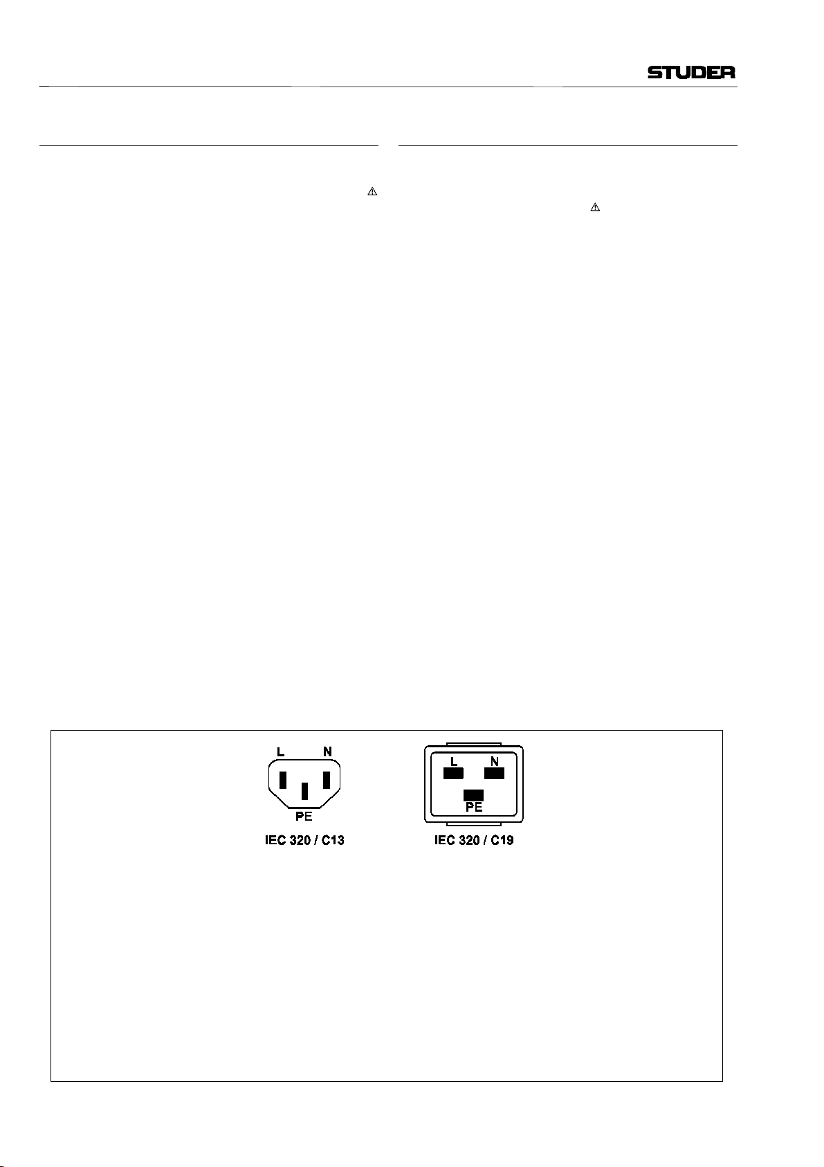
IEC320/C19 und unter Berücksichtigung der einschlägigen, im geweiligen Lande geltenden Bestimmungen angefertigt werden; siehe Bild unten.
Vor Anschluss des Netzkabels an die Netzsteckdose muss
überprüft werden, ob die Stromversorgungs- und Anschlusswerte des Gerätes (Netzspannung, Netzfrequenz)
innerhalb der erlaubten Toleranzen liegen. Die im Gerät
eingesetzten Sicherungen müssen den am Gerät
angebrachten Angaben entsprechen.
Ein Gerät mit einem dreipoligen Gerätestecker (Gerät der
Schutzklasse I) muss an eine dreipolige Netzsteckdose
angeschlossen und somit das Gerätegehäuse mit dem
Schutzleiter der Netzinstallation verbunden werden (Für
Dänemark gelten Starkstrombestimmungen, Abschnitt
107).
Installation, Operation, Disposal
Before you install the equipment, please read and adhere
to the following recommendations and all sections of
these instructions marked with .
Check the equipment for any transport damage.
A unit that is mechanically damaged or which has been
penetrated by liquids or foreign objects must not be
connected to the AC power outlet or must be immediately
disconnected by unplugging the power cable. Repairs
must only be performed by trained personnel in accordance
with the applicable regulations.
Should the equipment be delivered without a matching
mains cable, the latter has to be prepared by a trained
person using the attached female plug (IEC320/C13 or
IEC320/C19) with respect to the applicable regulations in
your country - see diagram below.
Before connecting the equipment to the AC power
outlet, check that the local line voltage matches the
equipment rating (voltage, frequency) within the admissible tolerance. The equipment fuses must be rated in
accordance with the specifications on the equipment.
Equipment supplied with a 3-pole appliance inlet (equipment conforming to protection class I) must be connected to a 3-pole AC power outlet so that the equipment
cabinet is connected to the protective earth conductor of
the AC supply (for Denmark the Heavy Current Regulations,
Section 107, are applicable).
IV
Female plug (IEC320), view from contact side:
L .........live; brown National American Standard: black
N ........ neutral; blue white
PE ...... protective earth; green and yellow green
Connecteur femelle (IEC320), vue de la face aux contacts:
L.......phase, brun Standard National Américain: noir
N......neutre, bleu blanc
PE....terre protective; vert et jaune vert
Ansicht auf Steckkontakte der Kabel-Gerätesteckdose (IEC320):
L......Polleiter, braun USA-Standard: schwarz
N......Neutralleiter, hellblau weiss
PE....Schutzleiter, gelb/grün grün
Page 5

SAFETY / SECURITE / SICHERHEIT
Bei der Installation des Gerätes muss vermieden werden,
dass:
€ das Gerät Regen, Feuchtigkeit, direkter Sonnen-
einstrahlung oder übermässiger Wärmestrahlung von
Wärmequellen (Heizgeräte, Heizungen, Spotlampen)
ausgesetzt wird
€ die für den Betrieb des Gerätes benötigte Luftzirkulation
beeinträchtigt und dadurch die zulässige maximale
Lufttemperatur der Geräteumgebung überschritten wird
(Wärmestau)
€ die Belüftungsöffnungen des Gerätes blockiert oder
abgedeckt werden.
Das Gerät und seine Verpackung darf nur sachgerecht
entsorgt werden. Alle Teile des Gerätes, die gefährliche
Stoffe (Quecksilber, Cadmium) enthalten, müssen als
Sondermüll behandelt werden.
Verbrauchte Batterien und Akkus müssen dem Hersteller zur Entsorgung zurückgegeben oder entsprechend
den spezifischen Bestimmungen Ihres Landes fachgerecht entsorgt werden.
Wartung und Reparatur
Durch Entfernen von Gehäuseteilen, Abschirmungen etc.
werden stromführende Teile freigelegt. Aus diesem Grund
müssen u.a. die folgenden Grundsätze beachtet werden:
Eingriffe in das Gerät dürfen nur von Fachpersonal unter
Einhaltung der geltenden Vorschriften vorgenommen
werden.
Vor Entfernen von Gehäuseteilen muss das Gerät
ausgeschaltet und vom Netz getrennt werden.
Bei geöffnetem, vom Netz getrenntem Gerät dürfen Teile
mit gefährlichen Ladungen (z. B. Kondensatoren,
Bildröhren) erst nach kontrollierter Entladung, heiße
Bauteile (Leistungshalbleiter, Kühlkörper etc.) erst nach
deren Abkühlen berührt werden.
The equipment installation must satisfy the following
requirements:
€ Protection against rain, humidity, direct solar irradiation
or strong thermal radiation from heat sources (heaters,
radiators, spotlights).
€ Unobstructed air circulation so that the maximum air
temperature in the equipment environment will not be
exceeded (no heat accumulation).
€ Ventilation louvers of the equipment must not be
blocked or covered.
The equipment and its packing materials should ultimately
be disposed of in accordance with the applicable
regulations only. All parts of the equipment that contain
hazardous substances (mercury, cadmium) must be treated
as toxic waste.
Weak batteries or exhausted rechargeable batteries must
be returned to the manufacturer for competent disposal
or must be disposed of in accordance with the environmental protection regulations applicable for your country.
Maintenance and Repair
The removal of housing parts, shields, etc. exposes
energized parts. For this reason the following precautions
should be observed:
Maintenance should only be performed by trained
personnel in accordance with the applicable regulations.
The equipment should be switched off and disconnected
from the AC power outlet before any housing parts are
removed.
Even after the equipment has been disconnected from
the power, parts with hazardous charges (e.g. capacitors,
picture tubes) should only be touched after they have
been properly discharged. Hot components (power semiconductors, heat sinks, etc.) should only be touched after
they have cooled off.
Bei Wartungsarbeiten am geöffneten, unter Netzspannung stehenden Gerät dürfen blanke Schaltungsteile und metallene Halbleitergehäuse weder direkt noch
mit einem nichtisolierten Werkzeug berührt werden.
Zusätzliche Gefahren bestehen bei unsachgemässer
Handhabung besonderer Komponenten:
€ Explosionsgefahr bei Lithiumzellen, Elektrolyt-Konden-
satoren und Leistungshalbleitern
€ Implosionsgefahr bei evakuierten Anzeigeeinheiten
€ Strahlungsgefahr bei Lasereinheiten (nichtionisierend),
Bildröhren (ionisierend)
€ Verätzungsgefahr bei Anzeigeeinheiten (LCD) und
Komponenten mit flüssigem Elektrolyt.
Solche Komponenten dürfen nur von dafür ausgebildetem Fachpersonal unter Verwendung von vorgeschriebenen Schutzmitteln (u.a. Schutzbrille, Handschuhe)
gehandhabt werden.
If maintenance is performed on a unit that is opened and
switched on, no uninsulated circuit components and
metallic semiconductor housings should be touched
neither with your bare hands nor with uninsulated tools.
Certain components pose additional hazards:
€ Explosion hazard from lithium batteries, electrolytic
capacitors and power semiconductors
€ Implosion hazard from evacuated display units
€ Radiation hazard from laser units (non-ionizing), pic-
ture tubes (ionizing)
€ Caustic effect of display units (LCD) and such compo-
nents containig liquid electrolyte.
Such components should only be handled by trained
personnel who are properly protected (e.g. by goggles,
gloves).
V
Page 6

SAFETY / SECURITE / SICHERHEIT
Für Wartung und Reparatur der sicherheitsrelevanten
Teile des Gerätes darf nur Ersatzmaterial nach
Herstellerspezifikation verwendet werden.
Das Gerät muss ordnungsgemäss und regelmässig gewartet und somit in sicherem Zustand erhalten werden.
Bei ungenügender Wartung oder bei Änderungen der
sicherheitsrelevanten Teile des Gerätes erlischt die
entsprechende Produktehaftung des Herstellers.
For maintenance work and repair on components that
influence the equipment safety, only replacement material conforming to the manufacturer’s specifications
may be used.
The equipment should be properly serviced in regular
intervals and be maintained in safe operating condition. If
the equipment is not properly maintained or if any
modifications are made to components that influence
safety, the manufacturer’s product liability gets void.
VI
Page 7

WARTUNG / MAINTENANCE
Elektrostatische Entladung (ESD) bei
Wartung und Reparatur
ATTENTION: Observe precautions for handling devices sensitive to
ATTENTION: Respecter les précautions d’usage concernant la mani-
ACHTUNG: Vorsichtsmassnahmen bei Handhabung elektrostatisch
Viele ICs und andere Halbleiter sind empfindlich gegen
elektrostatische Entladung (ESD). Unfachgerechte Behandlung von Baugruppen mit solchen Komponenten bei
Wartung und Reparatur kann deren Lebensdauer drastisch
vermindern.
Bei der Handhabung der ESD-empfindlichen Komponenten sind u.a. folgende Regeln zu beachten:
€ ESD-empfindliche Komponenten dürfen ausschliess-
lich in dafür bestimmten und bezeichneten Verpackungen gelagert und transportiert werden.
€ Unverpackte, ESD-empfindliche Komponenten dürfen
nur in den dafür eingerichteten Schutzzonen (EPA, z.B.
Gebiet für Feldservice, Reparatur- oder Serviceplatz)
gehandhabt und nur von Personen berührt werden, die
durch ein Handgelenkband mit Serienwiderstand mit
dem Massepotential des Reparatur- oder Serviceplatzes
verbunden sind. Das gewartete oder reparierte Gerät
wie auch Werkzeuge, Hilfsmittel, EPA-taugliche (elektrisch halbleitende) Arbeits-, Ablage- und Bodenmatten
müssen ebenfalls mit diesem Potential verbunden sein.
€ Die Anschlüsse der ESD-empfindlichen Komponenten
dürfen unkontrolliert weder mit elektrostatisch
aufladbaren (Gefahr von Spannungsdurchschlag), noch
mit metallischen Oberflächen (Schockentladungsgefahr)
in Berührung kommen.
€ Um undefinierte transiente Beanspruchung der Kompo-
nenten und deren eventuelle Beschädigung durch
unerlaubte Spannung oder Ausgleichsströme zu
vermeiden, dürfen elektrische Verbindungen nur am
abgeschalteten Gerät und nach dem Abbau allfälliger
Kondensatorladungen hergestellt oder getrennt werden.
Electrostatic Discharge (ESD) during
Maintenance and Repair
electrostatic discharge!
pulation de composants sensibles à l’électricité statique!
entladungsgefährdeter Bauelemente beachten!
Many ICs and semiconductors are sensitive to electrostatic
discharge (ESD). The life of components containing such
elements can be drastically reduced by improper handling
during maintenance and repair work.
Please observe the following rules when handling ESD
sensitive components:
€ ESD sensitive components should only be stored and
transported in the packing material specifically pro-
vided for this purpose.
€ Unpacked ESD sensitive components should only be
handled in ESD protected areas (EPA, e.g. area for field
service, repair or service bench) and only be touched by
persons who wear a wristlet that is connected to the
ground potential of the repair or service bench by a
series resistor. The equipment to be repaired or serviced
and all tools, aids, as well as electrically semiconducting
work, storage and floor mats should also be connected
to this ground potential.
€ The terminals of ESD sensitive components must not
come in uncontrolled contact with electrostatically
chargeable (voltage puncture) or metallic surfaces (dis-
charge shock hazard).
€ To prevent undefined transient stress of the compo-
nents and possible damage due to inadmissible voltages
or compensation currents, electrical connections should
only be established or separated when the equipment
is switched off and after any capacitor charges have
decayed.
VII
Page 8
WARTUNG / MAINTENANCE
SMD-Bauelemente
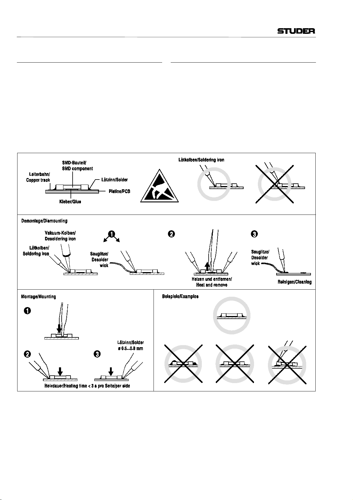
Der Austausch von SMD-Bauelementen ist ausschliesslich geübten Fachleuten vorbehalten. Für verwüstete Platinen können keine Ersatzansprüche geltend gemacht
werden. Beispiele für korrekte und falsche SMDLötverbindungen in der Abbildung weiter unten.
Bei Studer werden keine handelsüblichen SMD-Teile
bewirtschaftet. Für Reparaturen sind die notwendigen
Bauteile lokal zu beschaffen. Die Spezifikationen von
Spezialbauteilen finden Sie in der Serviceanleitung.
SMD Components
SMDs should only be replaced by skilled specialists. No
warranty claims will be accepted for circuit boards that
have been ruined. Proper and improper SMD soldering
joints are depicted below.
Studer does not keep any commercially available SMDs in
stock. For repair the corresponding devices should be
purchased locally. The specifications of special components
can be found in the service manual.
VIII
Page 9

EMV / EMC
Störstrahlung und Störfestigkeit
Das Gerät entspricht den Schutzanforderungen auf dem
Gebiet der elektromagnetischen Phänomene, die u.a. in
den Richtlinien 89/336/EWG und FCC, Part 15, aufgeführt
sind :
1. Die vom Gerät erzeugten elektromagnetischen
Aussendungen sind soweit begrenzt, dass ein bestimmungsgemässer Betrieb anderer Geräte und Systeme
möglich ist.
2. Das Gerät weist eine angemessene Festigkeit gegen
elektromagnetische Störungen auf, so dass sein
bestimmungsgemässer Betrieb möglich ist.
Das Gerät wurde getestet und erfüllt die Bedingungen der
im Kapitel „Technische Daten“ aufgeführten EMVStandards. Die Limiten dieser Standards gewährleisten mit
einer angemessenen Wahrscheinlichkeit sowohl einen
Schutz der Umgebung wie auch entsprechende Störfestigkeit des Gerätes. Eine absolute Garantie, dass keine
unerlaubte elektromagnetische Beeinträchtigung während
des Gerätebetriebes entsteht, ist jedoch nicht gegeben.
Um die Wahrscheinlichkeit solcher Beeinträchtigung
weitgehend auszuschliessen, sind u.a. folgende Massnahmen zu beachten:
€ Installieren Sie das Gerät gemäss den Angaben in der
Bedienungsanleitung, und verwenden Sie das
mitgelieferte Zubehör.
€ Verwenden Sie im System und in der Umgebung, in
denen das Gerät eingesetzt ist, nur Komponenten
(Anlagen, Geräte), die ihrerseits die Anforderungen der
obenerwähnten Standards erfüllen.
€ Sehen Sie ein Erdungskonzept des Systems vor, das
sowohl die Sicherheitsanforderungen (die Erdung der
Geräte gemäss Schutzklasse I mit einem Schutzleiter
muss gewährleistet sein), wie auch die EMV-Belange
berücksichtigt. Bei der Entscheidung zwischen sternoder flächenförmiger bzw. kombinierter Erdung sind
Vor- und Nachteile gegeneinander abzuwägen.
€ Benutzen Sie abgeschirmte Kabel für die Verbindungen,
für welche eine Abschirmung vorgesehen ist. Achten
Sie auf einwandfreie, grossflächige, korrosionsbeständige Verbindung der Abschirmung zum entsprechenden Steckeranschluss bzw. zum Steckergehäuse.
Beachten Sie, dass eine nur an einem Ende angeschlossene Kabelabschirmung als Sende- bzw.
Empfangsantenne wirken kann (z.B. bei wirksamer
Kabellänge von 5 m oberhalb von 10 MHz), und dass
die Flanken der digitalen Kommunikationssignale
hochfrequente Aussendungen verursachen (z.B. LSoder HC-Logik bis 30 MHz).
€ Vermeiden Sie Bildung von Stromschleifen oder ver-
mindern Sie deren unerwünschte Auswirkung, indem
Sie deren Fläche möglichst klein halten und den darin
fliessenden Strom durch Einfügen einer Impedanz (z.B.
Gleichtaktdrossel) reduzieren.
Electromagnetic Compatibility
The equipment conforms to the protection requirements
relevant to electromagnetic phenomena that are listed in
the guidelines 89/336/EC and FCC, part 15.
1. The electromagnetic interference generated by the
equipment is limited in such a way that other equipment and systems can be operated normally.
2. The equipment is adequately protected against electromagnetic interference so that it can operate correctly.
The unit has been tested and conforms to the EMC
standards applicable to residential, commercial and light
industry, as listed in the section „Technical Data“. The
limits of these standards reasonably ensure protection of
the environment and corresponding noise immunity of
the equipment. However, it is not absolutely warranted
that the equipment will not be adversely affected by
electromagnetic interference during operation.
To minimize the probability of electromagnetic interference as far as possible, the following recommendations
should be followed:
€ Install the equipment in accordance with the operating
instructions. Use the supplied accessories.
€ In the system and in the vicinity where the equipment
is installed, use only components (systems, equipment)
that also fulfill the above EMC standards.
€ Use a system grounding concept that satisfies the safety
requirements (protection class I equipment must be
connected with a protective ground conductor) that
also takes into consideration the EMC requirements.
When deciding between radial, surface or combined
grounding, the advantages and disadvantages should
be carefully evaluated in each case.
€ Use shielded cables where shielding is specified. The
connection of the shield to the corresponding
connector terminal or housing should have a large
surface and be corrosion-proof. Please note that a cable
shield connected only single-ended can act as a
transmitting or receiving antenna (e.g. with an effective
cable length of 5 m, the frequency is above 10 MHz)
and that the edges of the digital communication signals
cause high-frequency radiation (e.g. LS or HC logic up
to 30 MHz).
€ Avoid current loops or reduce their adverse effects by
keeping the loop surface as small as possible, and
reduce the noise current flowing through the loop by
inserting an additional impedance (e.g. common-mode
rejection choke).
IX
Page 10
Konformitätserklärungen / Declarations of Conformity
Class A Equipment - FCC Notice
This equipment has been tested and found to comply with the limits for a Class A digital device, pursuant to Part 15
of the FCC Rules. These limits are designed to provide a reasonable protection against harmful interference when the
equipment is operated in a commercial environment. This equipment generates, uses, and can radiate radio frequency
energy and, if not installed and used in accordance with the instruction manual, may cause harmful interference to radio
communications. Operation of this equipment in a residential area is likely to cause harmful interference in which case
the user will be required to correct the interference at his own expense.
Caution:
Any changes or modifications not expressly approved by the manufacturer could void the user's authority to
operate the equipment. Also refer to relevant information in this manual.
CE-Konformitätserklärung
Wir,
Studer Professional Audio AG,
CH-8105 Regensdorf,
erklären in eigener Verantwortung, dass das Produkt
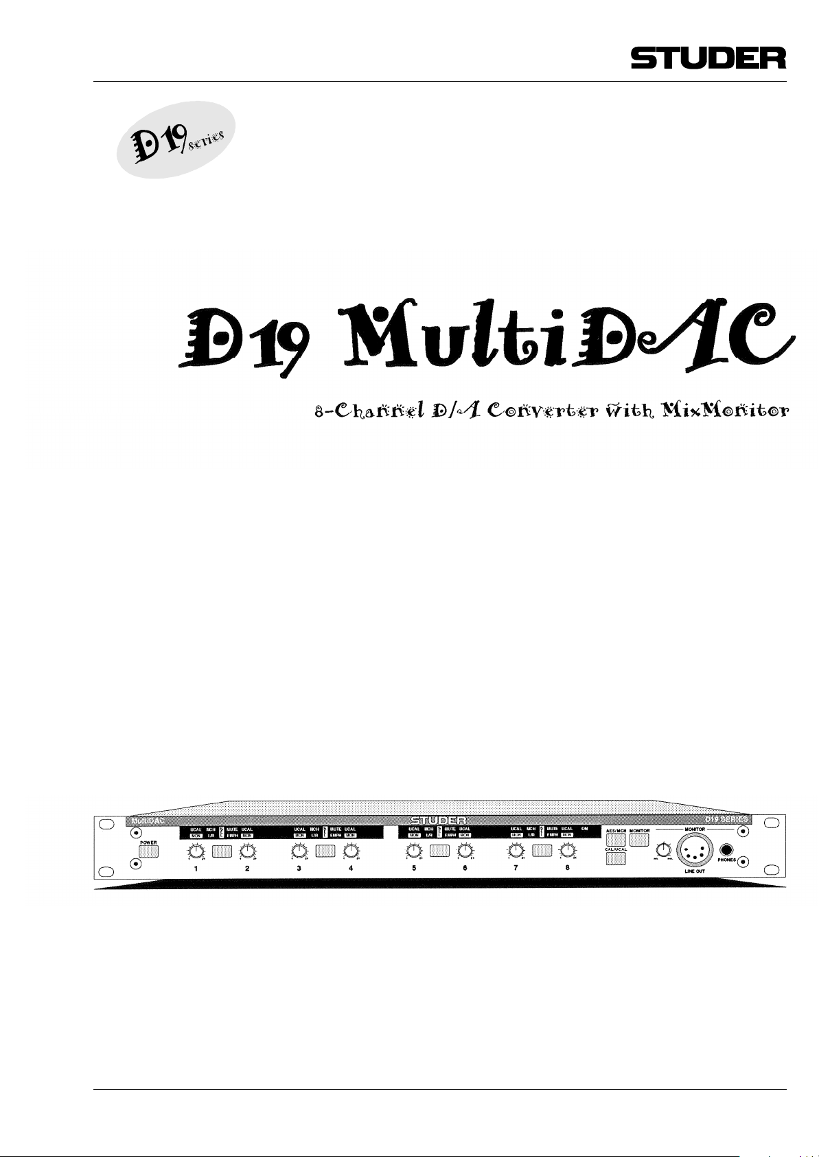
Studer D19 MultiDAC, 8-Channel D/A Converter
(ab Serie-Nr. 1001),
auf das sich diese Erklärung bezieht, entsprechend den
Bestimmungen der EU-Richtlinien und deren Ergänzungen
• Elektromagnetische Verträglichkeit (EMV):
89/336/EWG + 92/31/EWG + 93/68/EWG
• Niederspannung:
73/23/EWG, 93/68/EWG
mit den folgenden Normen und normativen Dokumenten
übereinstimmt:
• Sicherheit:
Schutzklasse I, EN 60950; 1992 + A1, A2; 1993
• EMV:
EN 50081-1; 1992, EN 50082-1; 1992
CE Declaration of Conformity
We,
Studer Professional Audio AG,
CH-8105 Regensdorf,
declare under our sole responsibility that the product
Studer D19 MultiDAC, 8-Channel D/A Converter
(from serial No. 1001 and up),
to which this declaration relates, according to following
regulations of EU directives and amendments
• Electromagnetic Compatibility (EMC):
89/336/EEC + 92/31/EEC + 93/68/EEC
• Low Voltage (LVD):
73/23/EEC + 93/68/EEC
is in conformity with the following standards or other
normative documents:
• Safety:
Class I, EN 60950; 1992 + A1, A2; 1993
• EMC:
EN 50081-1; 1992, EN 50082-1; 1992
Regensdorf, 3. September 1996
B. Hochstrasser, Geschäftsleiter
P. Fiala, Leiter QS
X
Regensdorf, September 3, 1996
B. Hochstrasser, Managing Director
P. Fiala, Manager QA
Page 11

INHALT
D19 MultiDAC
1 HEREINSPAZIERT!..................................................................... D 1/1
1.1 Basis-Information .................................................................... D 1/1
1.2 Allgemeines .............................................................................. D 1/2
1.2.1 Lieferumfang ..........................................................................D 1/2
1.2.2 Optionen ................................................................................D 1/2
1.2.3 Zubehör .................................................................................. D 1/2
1.3 Sicherheit und Anschlüsse ................................................... D 1/3
1.3.1 Bestimmungsgemässe Verwendung ..............................D 1/3
1.3.2 Netzanschluss .......................................................................D 1/3
1.3.3 Anschlussfeld.........................................................................D 1/4
1.4 Technische Daten................................................................... D 1/5
1.4.1 Audiodaten ............................................................................D 1/5
1.4.2 Stromversorgung ..................................................................D 1/5
1.4.3 Primärsicherung ....................................................................D 1/5
1.4.4 Betriebsbedingungen ..........................................................D 1/6
1.4.5 Sicherheits- und EMV-Normen ........................................ D 1/6
1.4.6 Mechanische Daten ............................................................D 1/6
2 BETRIEB ....................................................................................... D 2/1
2.1 Bedienungselemente............................................................. D 2/1
2.2 Audio-Anschlüsse, Stiftbelegungen ................................... D 2/3
2.2.1 AES/EBU, Digital-Eingang ...................................................D 2/3
2.2.2 Line-Ausgänge ....................................................................... D 2/3
2.2.3 MONITOR Phones ...............................................................D 2/3
2.2.4 MONITOR LINE OUT ..........................................................D 2/3
2.2.5 Anwendung der 8-Kanal-TDIF-1-Schnittstelle .............D 2/4
2.2.6 Anwendung der 8-Kanal-ADAT-Schnittstelle ..............D 2/5
2.3 Jumpers...................................................................................... D 2/6
2.3.1 Synchronisation ....................................................................D 2/6
2.3.2 Auto Mute .............................................................................. D 2/6
2.4 Ausgangspegel-Einstellung für kalibrierten Betrieb ....... D 2/7
2.5 Anwendungsbeispiele ........................................................... D 2/8
3 BLOCKSCHEMAS ..................................................................... D 3/1
3.1 Globales Audio-Blockschema ............................................. D 3/1
3.2 Synchronisations-Blockschema .......................................... D 3/1
«ADAT» ist ein Warenzeichen von Alesis Corporation.
«TDIF-1» ist ein Warenzeichen von Tascam Corporation.
Inhalt D 0/1Edition: 10.10.96
Page 12

1 HEREINSPAZIERT!
1.1 Basis-Information
D19 MultiDAC
Wir freuen uns, Sie im wachsenden Kreis der Anwender des Studer
D19 MultiDAC begrüssen zu dürfen, und beglückwünschen Sie zu Ihrer Wahl. Dank der Erfahrung, die Studer während mehr als 40 Jahren
auf dem Gebiet der professionellen Audiotechnik sammeln konnte,
dürfen Sie erwarten, dass Ihr neues Gerät Ihre hohen Ansprüche erfüllt.
Der Studer D19 MultiDAC enthält acht D/A-Wandler mit einer Auflösung von 23 bit. Zusätzlich zu den normalen Wandler-Funktionen wurden nützliche Erweiterungen integriert, daher finden sich auf der Frontplatte einige einfache, ergonomisch ausgelegte Bedienelemente. Acht
Potentiometer dienen einer doppelten Funktion: Zur Einstellung des
Ausgangspegels (in unkalibriertem Betrieb) oder zur Einstellung eines
Monitorpegels. LED-Anzeigen für Signalqualität (MUTE) und Deemphasis-Flag (EMPH) sind ebenfalls vorgesehen. In einem zentralen
Bedienfeld können die digitale Quelle (AES/MCH) und die CAL/UCALFunktion gewählt werden. Mit einer SELect-Taste pro Wandlerpaar
kann dieses zur Bedienung durch dieses zentrale Bedienfeld aufgeschaltet werden.
MixMonitor: Neben einer hochqualitativen Wandlung von Digitalsignalen besteht
oft auch der Wunsch, das gewandelte Signal optimal abhören zu können. Mit Hilfe der MixMonitor-Funktion können die acht Einganssignale (vier AES/EBU-Paare) mono oder stereo abgehört werden; auch
eine individuelle Mischung ist möglich. Die zugehörigen Bedienelemente befinden sich auf der rechten Seite der Frontplatte und umfassen neben dem Lautstärke-Drehknopf einen Kopfhöreranschluss und
einen 5-poligen XLR-Stecker (elektronisch symmetriertes Stereo-Signal
mit Leitungspegel). MixMonitor hat eine ganze Reihe von Einsatzmöglichkeiten, wie z.B. direkte Hinterbandkontrolle von Achtspur-Digitalrecordern. Daneben lassen sich einzelne Kanäle abhören oder messen. In der kalibrierten Stellung der einzelnen Ausgänge beeinflusst
die Einstellung des Abhörweges den Ausgangspegel nicht. Der
MultiDAC ist daher nicht nur ein hochwertiger D/A-Wandler, sondern
auch ein Achtkanal-Mischer.
Anschlüsse: Zur Vereinfachung der Systemverbindungen ist der MultiDAC mit den
selben Anschlüssen wie sein Bruder, der MicAD, ausgerüstet. Standardmässig ist das Gerät mit vier AES/EBU-Eingängen bestückt, ADAT- oder
TDIF-1-kompatible Eingänge stehen als Option zur Verfügung. Jedes
Eingangs-Kanalpaar kann individuell entweder von seinem AES/EBUAnschluss oder von den entsprechenden Kanälen des Mehrkanal-Anschlusses mit Signal versorgt werden. Die acht analogen Ausgänge sind
transformator-symmetriert und auf einzelne XLR-Stecker geführt.
Edition: 10.10.96
Synchronisation: Die acht D/A-Wandler arbeiten in einem weiten Abtastraten-Bereich;
ein externes Synchronisationssignal ist nicht erforderlich, da jeder Eingang seinen eigenen, asynchronen Abtastratenwandler enthält. Falls
Hereinspaziert! D 1/1
Page 13

D19 MultiDAC
notwendig, kann jeder der Eingänge mit einer unabhängigen Abtastrate arbeiten. Soll aus Systemgründen ein fester Takt gewählt werden,
kann der MultiDAC intern so eingestellt werden, dass ein beliebiger
Eingang (AES/EBU oder Mehrkanal) als feste Referenz für alle D/AWandler dient; auf diese Weise können allfällige Phasenfehler vermieden werden.
1.2 Allgemeines
1.2.1 Lieferumfang
Der D19 MultiDAC (Bestell-Nr. 66.660.000.00) wird mit einer Kaltgerätekupplung (IEC 320/C13), einem Inbus-Schraubendreher (2,5 mm)
und dieser Betriebsanleitung geliefert.
1.2.2 Optionen Bestell-Nr.
Optionale Digital-Audio-Eingänge:
ADAT-Schnittstelle: 8-kanalige, optische Digitalaudio-Eingangs- 1.660.050.20
karte
für den Anschluss von ADAT- und kompatiblen
Achtspur-Bandgeräten oder anderen Geräten,
die mit den ADAT-Standardanschlüssen ausgestattet sind.
TDIF-1-Schnittstelle: 8-kanalige Digitalaudio-Eingangskarte 1.660.052.20
für den Anschluss von DA-88- und kompatiblen
Achtspur-Bandgeräten oder anderen Geräten,
die mit den TDIF-1-Standardanschlüssen ausgestattet sind.
1.2.3 Zubehör Bestell-Nr.
Zubehör und Ersatzteile: Set, bestehend aus: 20.020.302.52
• XLR-Steckverbinder (4 Stecker und 8 Kupplungen dreipolig, 1 Kupplung 5-polig)
• Drehknöpfe (2 Stück)
• Schrauben und Unterlegscheiben für Rack-
einbau (je 4 Stück)
Schnittstellenkabel: ADAT/Alesis, optisches Verbindungskabel, 10.325.010.00
Länge 1,0 m
ADAT/Alesis, optisches Verbindungskabel, 10.325.011.00
Länge 5,0 m
TDIF-1/Tascam-Verbindungskabel F-10.025.031.08
«PW 88D», Länge 1,0 m
TDIF-1/Tascam-Verbindungskabel F-10.025.031.09
«PW 88D», Länge 5,0 m
D 1/2 Hereinspaziert! Edition: 10.10.96
Page 14

1.3 Sicherheit und Anschlüsse
1.3.1 Bestimmungsgemässe Verwendung
Der Studer D19 MultiDAC ist für den professionellen Betrieb konzipiert. Es wird vorausgesetzt, dass das Gerät ausschliesslich durch dafür
geschulte Personen bedient und durch Fachpersonal gewartet wird.
Die elektrischen Anschlüsse dürfen nur mit den in dieser Betriebsanleitung bezeichneten Spannungen und Signalen verbunden werden. Bitte
lesen Sie dazu auch die Abschnitte «Sicherheit» und «EMV» in der Einleitung dieser Betriebsanleitung.
1.3.2 Netzanschluss
Das Gerät hat keinen Spannungswähler. Es kann mit beliebigen Wechselspannungen im Bereich von 100 bis 240 VAC, 50 bis 60 Hz, betrieben
werden.
Wichtig! Eingriffe im Inneren des Gerätes dürfen nur von geschulten Service-Tech-
nikern vorgenommen werden.
Sicherungen dürfen nur durch solche des selben Typs ersetzt werden.
Das Gerät darf vom Benützer nicht geöffnet werden – Risiko eines gefährlichen elektrischen Schlages!
D19 MultiDAC
Netzkabel: Die mitgelieferte Kaltgerätedose muss durch einen Elektriker mit ei-
nem passenden Netzkabel mit Netzstecker versehen werden, wenn
Ihre lokale Studer-Vertretung oder Ihr Fachhändler kein passendes
Netzkabel beigelegt hat.
* Bitte lesen Sie dazu den Abschnitt «Sicherheit» in der Einleitung
dieser Betriebsanleitung.
Edition: 10.10.96
Hereinspaziert! D 1/3
Page 15

D19 MultiDAC
1.3.3 Anschlussfeld
[1] 100 – 240 V Anschluss für Kaltgeräte-Kabeldose IEC 320/C13.
Netzspannungsbereich 100...240 VAC (ohne Spannungswähler);
Netzfrequenz 50...60 Hz.
Vor dem Anschliessen ans Netz lesen Sie bitte die Seiten «Sicherheit»
ganz am Anfang dieser Anleitung.
[2] AES/EBU IN Eingänge für vier digitale Eingangssignale gemäss AES/EBU, mit weibli-
chem XLR-Anschluss.
[3] LINE OUTPUTS Analoge Line-Ausgänge mit männlichen XLR-Anschlüssen. Ausgangs-
impedanz ≤40 Ω, transformator-symmetriert.
[4] MCH IN Optionale, digitale Mehrkanal-Eingänge; wahlweise TDIF-1-Achtkanal-
Format oder optisches ADAT-Achtkanal-Format.
D 1/4 Hereinspaziert! Edition: 10.10.96
Page 16

1.4 Technische Daten (Änderungen vorbehalten)
D19 MultiDAC
1.4.1 Audiodaten (20 Hz...20 kHz, bei +15 dBu
, wenn nicht anders spezifiziert)
FS
D/A-Wandlung: Auflösung 23 bit, linear.
LINE OUTPUT:
Frequenzgang: ±0,1 dB
Geräuschspannungsabstand: > 115 dB, unbewertet, Auto Mute OFF, +24 dBu
> 119 dB, unbewertet, Auto Mute ON, +24 dBu
THD+N: < –80 dBFS, bei 0 dB
< –110 dB
(typ. –112 dBFS), bei -30 dB
FS
FS
FS
Übersprechen: < –95 dB (typ. –100 dB)
< –110 dB, 1 kHz
Ausgangsimpedanz: typ. <30 Ω
max. <40 Ω
Maximaler Ausgangspegel: typ. 24 dBu (Last 100 kΩ)
typ. 23,5 dBu (Last 600 Ω)
MONITOR OUTPUT:
Frequenzgang: ±0,1 dB
THD+N: < –80 dBFS, bei 0 dBFS, 1 kHz
< –110 dB
(typ. –112 dBFS), bei -30 dBFS, 1 kHz
FS
Ausgangsimpedanz: <50 Ω (LINE OUT)
100 Ω (PHONES)
FS
FS
Maximaler Ausgangspegel: typ. 24 dBu (Last 100 kΩ)
typ. 23,5 dBu (Last 600 Ω)
1.4.2 Stromversorgung
Netzspannung: 100...240 VAC, 50...60 Hz
Stromaufnahme: 1...0,5 A
Netzanschluss: IEC 320/C14
1.4.3 Primärsicherung
Gefahr: Die Primärsicherung ist im Inneren des Gerätes angeordnet. Eingriffe im
Inneren des Gerätes dürfen nur von geschulten Service-Technikern vorgenommen werden. Die Sicherung darf nur durch eine solche des selben Typs ersetzt werden. Das Gerät darf vom Benützer nicht geöffnet
werden – Risiko eines gefährlichen elektrischen Schlages!
Ersatztyp: T 2,0 A H 250 V UL, CSA (5 × 20 mm) Bestell-Nr. 51.01.1022
Edition: 10.10.96
Hereinspaziert! D 1/5
Page 17

D19 MultiDAC
1.4.4 Betriebsbedingungen
Umgebungstemperatur: +10°...+40°C
Rel. Luftfeuchtigkeit: Klasse F (DIN 40040)
1.4.5 Sicherheits- und EMV-Normen
Sicherheit: Schutzklasse I gemäss EN 60950; 1992 + A1/A2; 1993 (UL 1950)
EMV: Produktfamiliennorm für Audio-, Video- und audiovisuelle Einrichtun-
gen sowie für Studio-Lichtsteuereinrichtungen für den professionellen
Einsatz.
Störaussendung: EN 50081-1; 1992
Störfestigkeit: EN 50082-1; 1992
1.4.6 Mechanische Daten
Gewicht: ca. 5 kg
Abmessungen: [mm]
D 1/6 Hereinspaziert! Edition: 10.10.96
Page 18

D19 MultiDAC
2 BETRIEB
2.1 Bedienungselemente
[1] POWER Versenkte Drucktaste, schaltet das Gerät ein und aus. Während der
Initialisierungsphase (einige Sekunden nach dem Einschalten) sind die
Ausgänge stummgeschaltet, alle SEL-LEDs blinken, und alle Tasten sind
gesperrt. Ist das Gerät eingeschaltet, so leuchtet zumindest die gelbe
ON-LED rechts im rechten Anzeigefenster.
Das Gerät ist mit den Werkseinstellungen betriebsbereit. Geräteeinstellungen bleiben auch nach dem Ausschalten in einem Flash-EPROM
erhalten; das Gerät benötigt keine Stützbatterie.
[2] Potentiometer 1...8 Potentiometer mit Mehrfachfunktion:
MixMonitor: Jeder der Kanäle kann jederzeit den Monitor-Ausgängen zugeschaltet
und -gemischt werden – abhängig von der Einstellung MONITOR [5] –
entweder beiden oder nur einem der Monitor-Kanäle. Einstellbereich:
20 dB am Potentiometer [2].
UCAL: In Stellung UCAL beeinflussen die Potentiometer sowohl den Pegel
des Ausgangs mit der selben Nummer (Einstellbereich: +4...+24 dBu
bei 0 dBFS) wie auch den Monitor-Mix. Siehe auch CAL/UCAL [6].
Headroom: Die Einstellung für den Ausgangspegel ist in dBu für Vollaussteuerung
angegeben; ein Eingangssignal mit 0 dBFS bewirkt Vollaussteuerung am
Ausgang des D/A-Wandlers. Damit die Pegelverhältnisse im Systemverbund mit A/D-Wandlern und anderen Studiogeräten gewährt bleiben, kann bzw. muss eine Übersteuerungsreserve (Headroom) eingestellt werden.
Beispiel: Nominalpegel im Studio +6 dBu, die gewünschte Übersteuerungs-
reserve beträgt 12 dB; der Spitzenpegel bei 0 dBFS beträgt also +18 dBu;
Einstellung im unkalibrierten Betrieb (UCAL leuchtet) mit Potentiometer [2].
Siehe auch CAL/UCAL [6].
(Panel-) Einstellung = Nominalpegel +Übersteuerungsreserve [dB]
[3] SEL Tasten zur Zuordnung der globalen Funktionstasten (AES/MCH [4],
MONITOR [5], CAL/UCAL [6]) zu den Kanalpaaren.
Edition: 10.10.96
Betrieb D 2/1
Page 19

D19 MultiDAC
SEL-Taste des gewünschten Kanals drücken (oder eine SEL-Taste gedrückt lassen und SEL-Tasten von weiteren, zusätzlich gewünschten
Kanälen drücken), die betreffenden gelben SEL-LEDs leuchten. Die
Funktionstasten AES/MCH, MONITOR, CAL/UCAL bewirken nun Umschaltung der entsprechenden Funktion. Ein zweiter Druck auf eine
SEL-Taste schaltet die Zuordnung und die LED wieder aus.
[4] AES/MCH Umschalten des mit SEL [3] vorgewählte Kanalpaares vom AES/EBU-
Eingang auf das entsprechende Kanalpaar des MCH-Einganges (MCHLED leuchtet); falls kein MCH-Interface bestückt ist oder kein Eingangssignal anliegt, leuchtet die rote MUTE-LED.
[5] MONITOR Wahl des Abhör-Modus der beiden Ausgänge LINE OUT und PHONES.
Ist ein Kanalpaar mit SEL vorgewählt, können mit der MONITOR-Taste
fünf Zustände zyklisch abgerufen werden:
1. Abhören nur des linken Kanals (z.B. Kanal 1) auf beiden Abhör-Kanälen
(grüne MON-LED von Kanal 1 leuchtet);
2. Abhören nur des rechten Kanals (z.B. Kanal 2) auf beiden Abhör-Kanä-
len (grüne MON-LED von Kanal 2 leuchtet);
3. Abhören des linken und des rechten Kanals zu einem Mono-Signal
summiert auf beiden Abhör-Kanälen (grüne MON-LEDs der Kanäle 1
und 2 leuchten);
4. Zweikanaliges Abhören des linken und des rechten Kanales (grüne LED
L/R und grüne MON-LEDs der Kanäle 1 und 2 leuchten);
5. Kein Abhören des linken und des rechten Kanales (beide MON-LEDs
sind dunkel).
[6] CAL/UCAL Die Potentiometer [1] bis [8] für die Pegeleinstellung der einzelnen
Kanäle können mit UCAL aktiviert werden (gelbe LEDs UCAL leuchten); Einstellbereich +4...+24 dBu bei 0 dBFS. Falls sie nicht aktiviert sind,
ist der Pegel aller Ausgänge mit Ausnahme der MONITOR-Ausgänge
LINE OUT und PHONES fest.
Beispiel: Nominalpegel im Studio +6 dBu, die Übersteuerungsreserve beträgt
9 dB; der Spitzenpegel bei 0 dBFS beträgt also 15 dBu (Werkseinstellung
in kalibriertem Betrieb, UCAL leuchtet nicht). Wird ein anderer Headroom-Wert für kalibrierten Betrieb gewünscht, kann dies im Geräteinneren mit einem Trimmpotentiometer pro Kanal eingestellt werden
(Einstellbereich +4...+24 dBu bei 0 dBFS; siehe 2.4).
(Panel-) Einstellung = Nominalpegel +Übersteuerungsreserve [dB]
Hinweis: Für die MONITOR-Ausgänge LINE OUT und PHONES sind die Poten-
tiometer «1» bis «8» immer aktiv – dadurch kann ein von den Hauptausgängen unabhängiger, zweikanaliger Monitor-Mix erstellt werden
(siehe Funktion «MixMonitor»).
D 2/2 Betrieb
Edition: 10.10.96
Page 20

D19 MultiDAC
[7] MONITOR-Potentiometer Pegeleinstellung des Kopfhörer- und des LINE OUT-Ausgangs an der
Frontplatte.
[8] LINE OUT 5-poliger XLR-Einbaustecker; zweikanaliger, elektronisch symmetrierter
Monitor-Ausgang für den Monitor-Mix. Einstellung des Summenpegels
mit dem Potentiometer MONITOR [7].
[9] PHONES 6,3-mm-Klinkenbuchse (Ausgangsimpedanz 100 Ω), für Kopfhörer mit
Impedanzen >200 Ω. Einstellung des Summenpegels mit dem Potentiometer MONITOR [7].
Im Kopfhörer-Verstärker ist ein Binaural-Konverter integriert, der die
Im-Kopf-Lokalisation eliminiert. Auch ausgedehnte Hörsitzungen sind
dadurch weit weniger ermüdend.
2.2 Audio-Anschlüsse, Stiftbelegungen
2.2.1 AES/EBU, Digital-Eingang (XLR-3f)
Pin Bezeichnung
1
Masse
2
Eingang +
3
Eingang –
-
Chassis
2.2.2 LINE-Ausgänge (XLR-3m, transformator-symmetriert)
Pin Bezeichnung
1
Masse
2
Ausgang +
3
Ausgang –
-
Chassis
2.2.3 MONITOR PHONES (TRS-Klinke, 6,3 mm)
Pin Bezeichnung
T (Tip)
R (Ring)
S (Sleeve)
Links
Rechts
Masse
2.2.4 MONITOR LINE OUT (XLR-5m, eletronisch symmetriert)
Pin Bezeichnung
1
Masse
2
Ausgang + links
3
Ausgang – links
4
Ausgang + rechts
5
Ausgang – rechts
-
Chassis
Edition: 10.10.96
Betrieb D 2/3
Page 21

D19 MultiDAC
2.2.5 Anwendung der 8-Kanal-TDIF-1-Schnittstelle
Das Tascam-Format TDIF-1 für digitale Ein- und Ausgänge kann zum
Senden digitaler Audiodaten von DA-88- und kompatiblen AchtkanalGeräten (oder auch vom D19 MicAD bzw. MicVALVE) zum D19
MultiDAC benützt werden.
Basis-Eigenschaften: 8-Kanal-Audiodaten mit Informationen über Abtastfrequenz und Em-
phasis, mit Sync-Signal.
Übertragungspegel C-MOS, asymmetrisch.
Kabel: Bestell-Nr.: F-10.025.031.08 (1,0 m)
F-10.025.031.09 (5,0 m)
Wichtig: Die Kabellänge sollte 10 m nicht überschreiten.
Es wird empfohlen, nur die angegebenen Verbindungskabel zu benützen (Bestell-Nummern siehe oben).
Pinbelegung:
Pin Bezeichnung
1
2
3
4
5
6
7
8
9
10
11
12
13
14
15
16
17
18
19
20
21
22
23
24
25
(DOUT 1/2)
(DOUT 3/4)
(DOUT 5/6)
(DOUT 7/8)
(LRCK OUT)
(FS 1 OUT)
GND
FS 1 IN
LRCK IN
DIN 7/8
DIN 5/6
DIN 3/4
DIN 1/2
GND
GND
GND
GND
(EMPHASIS OUT)
(FS 0 OUT)
FS 0 IN
EMPHASIS IN
GND
GND
GND
GND
D 2/4 Betrieb
Edition: 10.10.96
Page 22

D19 MultiDAC
Kabel-Konfiguration:
25-pol D-Typ, m Aderfarben (verdrillte Paare) 25-pol D-Typ, m
1
14
2
15
3
16
4
17
5
9
7
18
6
19
8
20
21
Schirm + Gehäuse
10
22
11
23
12
24
13
25
org/red 1
org/blk 1
gry/red 1
gry/blk 1
wht/red 1
wht/blk 1
yel/red 1
yel/blk 1
pnk/red 1
pnk/blk 1
org/red 2
org/blk 2
gry/red 2
gry/blk 2
wht/red 2
wht/blk 2
yel/red 2
yel/blk 2
pnk/red 2
pnk/blk 2
org/red 3
org/blk 3
gry/red 3
gry/blk 3
wht/red 3
wht/blk 3
13
25
12
24
11
23
10
22
9
5
7
21
8
20
6
19
18
Schirm + Gehäuse
4
17
3
16
2
15
1
14
2.2.6 Anwendung der optischen 8-Kanal-ADAT-Schnittstelle
Das ADAT-Format ist ein serielles Achtkanal-Format und benützt ein
einzelnes Fiberoptik-Kabel.
Steckertyp: TOCP 155 k
Lichtleiterverbindung: TOFC 100
Die empfohlene Maximallänge der Verbindung gemäss Alesis-Spezifikation beträgt 1 m; in den meisten Fällen sind jedoch Verbindungen
mit einer Länge von 10...15 m möglich.
Edition: 10.10.96
Betrieb D 2/5
Page 23

D19 MultiDAC
2.3 Jumpers
Wichtig! Eingriffe im Inneren des Gerätes dürfen nur von geschulten Service-Tech-
2.3.1 Synchronisation
AES1...4: Der betreffende AES/EBU-Eingang ist die Sync-Referenz.
OFF (Werkseinstellung): Jeder Wandler bezieht das Synchronisationssignal von seinem eige-
MCH: Der MCH-Eingang ist die Sync-Referenz.
nikern vorgenommen werden.
Vor dem Öffnen des Gerätes Netzstecker ziehen!
Zum Öffnen des Gerätes werden sechs IS-Schrauben Nr. 2,5 gelöst –
je zwei links und rechts, zwei auf der Oberseite. Darauf kann der Gehäusedeckel abgehoben werden.
Für normale Anwendungen synchronisiert sich jeder Wandler selbsttätig mit seinem Eingangssignal. Zur Vermeidung von Phasenproblemen in System-Installationen kann ein beliebiger der Eingänge
als gemeinsame Synchronisations-Referenz bestimmt werden. Diese
Wahl geschieht durch einen Jumper mit mehreren Positionen.
nen AES/EBU-Eingangssignal.
2.3.2 Auto Mute
Werkseinstellung: AUTO MUTE OFF.
Zusätzlich zur Standard-Stummschaltung können die eingesetzten
D/A-Wandler eine interne Stummschaltung aktivieren. Dies bewirkt
eine Verbesserung des Geräuschspannungs-Abstands um rund 3 dB
auf Kosten eines geringfügigen Klickens, das jedoch in der Regel nur
bei sehr hoher Abhörlautstärke wahrnehmbar wird.
Bedingungen für AUTO MUTE:
• Jumper ist in Stellung AUTO MUTE ON
• Der Digitaleingang erhält während mindestens ca. 8000 Samples die
Information «digital Null».
D 2/6 Betrieb
Edition: 10.10.96
Page 24

2.4 Ausgangspegel-Einstellung für kalibrierten Betrieb (CAL)
Wichtig! Eingriffe im Inneren des Gerätes dürfen nur von geschulten Service-Tech-
nikern vorgenommen werden.
Vor dem Öffnen des Gerätes Netzstecker ziehen!
Zum Öffnen des Gerätes werden sechs IS-Schrauben Nr. 2,5 gelöst –
je zwei links und rechts, zwei auf der Oberseite. Darauf kann der Gehäusedeckel abgehoben werden.
Werkseinstellung: 15 dBu für 0 dBFS.
Der Ausgangspegel für kalibrierten Betrieb ist in den selben Grenzen
einstellbar wie für unkalibrierten Betrieb (+4...+24 dBu für 0 dBFS). Die
Trimmpotentiometer (RA9...16) für diese Einstellung sind direkt hinter
den Potentiometern 1...8 [2] (RA17...24) im Inneren des Gerätes angeordnet.
Einstellung: Digitalsignal mit bekanntem Pegel (z.B. Mess-CD mit 0 dBFS) an einem
der Eingänge AES/EBU IN einspeisen.
Kalibrierten Pegel wählen (UCAL-LED leuchtet nicht).
Pegelmesser am entsprechenden Ausgang anschliessen.
Mit entsprechendem Trimmpotentiometer auf den gewünschten Pegel einstellen, Übersteuerungsreserve (Headroom) berücksichtigen
(siehe auch 2.1).
Einstellung für alle Kanäle durchführen.
D19 MultiDAC
Edition: 10.10.96
Betrieb D 2/7
Page 25

D19 MultiDAC
2.5 Anwendungsbeispiele
Systembaustein, z.B. für Multiformat-Monitoring: Portables Studio oder Direct-to-track-Aufnahme:
• Modulares, aufrüstbares System • Verbesserung der Klangqualität
• Hohe Wandlerqualität • Direct-to-track-Aufzeichnung
• Hohe Packungsdichte • Tragbar
• Kalibrierter Betrieb für feste Studiopegel • Hinterbandkontrolle
• Flexible Synchronisation • 8-Kanal-Mischer
Bühnen-Monitorsystem: Universal-D/A-Wandler und -Mischer:
• Bühnen-Ausgänge hoher Qualität für digitale • Multisync-Betrieb
Systeme • Wandler hoher Qualität
• Pegel-Einstellung für individuelle Ausgänge, • 8-Kanal-Mischer
für Abhörmischung
D 2/8 Betrieb
Edition: 10.10.96
Page 26

3 BLOCKSCHEMAS
3.1 Globales Audio-Blockschema
D19 MultiDAC
3.2 Synchronisations-Blockschema
Edition: 10.10.96
Blockschemas D 3/1
Page 27

CONTENTS
D19 MultiDAC
1 COME IN! .....................................................................................E1/1
1.1 Basic information ....................................................................... E1/1
1.2 General ......................................................................................... E1/2
1.2.1 Scope of delivery ................................................................... E1/2
1.2.2 Options ..................................................................................... E1/2
1.2.3 Accessories .............................................................................. E1/2
1.3 Safety and connections ........................................................... E1/3
1.3.1 Utilization for the purpose intended ............................... E1/3
1.3.2 Power connection ................................................................. E1/3
1.3.3 Connector field ...................................................................... E1/4
1.4 Technical specifications ........................................................... E1/5
1.4.1 Audio data ............................................................................... E1/5
1.4.2 Power supply ........................................................................... E1/5
1.4.3 Primary fuse ............................................................................. E1/5
1.4.4 Operating conditions ............................................................ E1/6
1.4.5 Safety and EMC standards ................................................... E1/6
1.4.6 Mechanical data ..................................................................... E1/6
2 OPERATION .................................................................................E2/1
2.1 Operating elements .................................................................. E2/1
2.2 Audio connections, pin assignments ................................... E2/3
2.2.1 AES/EBU, digital input ........................................................... E2/3
2.2.2 Line outputs ............................................................................. E2/3
2.2.3 MONITOR Phones ................................................................. E2/3
2.2.4 MONITOR LINE OUT ............................................................ E2/3
2.2.5 Using the 8-channel TDIF-1 interface .............................. E2/4
2.2.6 Using the 8-channel ADAT interface ............................... E2/5
2.3 Jumpers......................................................................................... E2/6
2.3.1 Synchronisation ...................................................................... E2/6
2.3.2 Auto Mute ................................................................................ E2/6
2.4 Output level setting for calibrated mode .......................... E2/7
2.5 Application examples ............................................................... E2/8
3 BLOCK DIAGRAMS ....................................................................E3/1
3.1 Global audio block diagram ................................................... E3/1
3.2 Synchronisation block diagram ............................................. E3/1
Edition: 10.10.96
“ADAT” is a trade mark of Alesis Corporation.
“TDIF-1” is a trade mark of Tascam Corporation.
Contents E 0/1
Page 28

1 COME IN!
1.1 Basic information
D19 MultiDAC
We are happy to welcome you in the steadily growing circle of the
Studer D19 MultiDAC's users, and we felicitate you on your selection.
Thanks to Studer's experience collected during more than 40 years of
business in the professional audio products field, you may expect that
the perfomance of your new unit will fulfill your highest demands.
The Studer D19 MultiDAC contains eight D/A converters with 23 bit
resolution. Rather than just having basic D/A functions, some enhancement features have been included. For this reason, a few simple and
ergonomically laid out operating elements are found.
Eight potentiometers have a dual function – they serve as output level
controls in the uncalibrated mode and/or as monitor level controls. In
the calibrated position, the output level is set internally. LED indicators
for signal quality (MUTE) and deemphasis flag (EMPH) are also included.
A SEL button selects a channel to the central operating area.
MixMonitor: Next to high-quality conversion there is always the wish for suitable
monitoring. The MixMonitor function allows front panel listening of
any of the outputs in mono or stereo for easy and quick control of any
of the channels. Any combination of the output channels can be mixed
to the monitor output in mono or stereo for listening to up to 8 channels.
The MixMonitor controls are situated on the right side of the front
panel and comprise a headphones jack, a 5-pin balanced line level
XLR output and a volume control. With the MixMonitor function a
variety of tasks can be performed, such as direct off-track monitor mixing when the unit is used in conjunction with a MDM recorder for
direct-to-track recording. Obviously, any channel can also individually
be selected to the Monitor output for checking or measurements. In
the calibrated mode the line outputs have a fixed gain, and the channel
potentiometers only influence the monitor mix. So the MultiDAC is
not only a high-quality D/A converter, but also an 8-channel mixer.
Connections: To simplify system connection the MultiDAC is equipped with exactly
the same audio interface types as the MicAD. The MultiDAC is delivered with four AES/EBU inputs as standard and there is a selection of
ADAT or TDIF-1 multichannel input cards as options. This enables direct connection of the popular 8-channel Modular Digital Multitrack
recorders. Any channel pair can be selected to take its signal either
from the AES/EBU input or from the corresponding channel of the
multichannel card. The eight analogue outputs are transformer balanced and have XLR connectors.
Edition: 10.10.96
Synchronisation: The individual D/A converters can operate from a wide range of sam-
pling frequencies. There is no need for an external sync signal because
each D/A converter is equipped with an asynchronous sampling frequency converter synchronising to the incoming signals; i.e., each input can work with a different sampling rate if needed.
Come in! E 1/1
Page 29

D19 MultiDAC
Should a fixed sync reference be required in order to avoid phase
problems in system installations, the MultiDAC can be internally
switched to use one of the inputs (any AES or MCH) as a reference for
all D/A converters.
1.2 General
1.2.1 Scope of delivery
The D19 MultiDAC (Order No. 66.660.000.00) is shipped with an
IEC 320/C13 socket, a hex-socket screwdriver (2.5 mm), and this operating manual.
1.2.2 Options Order No.
Digital audio input options:
ADAT interface: 8-channel optical digital audio input card 1.660.050.20
for connecting to ADAT and compatible
8-channel recorders or other equipment
featuring the ADAT standard connectors.
TDIF-1 interface: 8-channel digital audio input card 1.660.052.20
for connecting to DA-88 and compatible
8-channel recorders or other equipment
featuring the TDIF-1 standard connectors.
1.2.3 Accessories Order No.
Accessories/spares: Kit, consisting of: 20.020.302.52
• XLR connectors (4 pcs male, 8 pcs female,
1 pce 5-pin female)
• Rotary knobs (2 pcs)
• Rack mounting screws with washers
(4 pcs each)
Interface cables: ADAT/Alesis, optical interface cable, 10.325.010.00
length 1.0 m
ADAT/Alesis, optical interface cable, 10.325.011.00
length 5.0 m
TDIF-1/Tascam interface cable F-10.025.031.08
“PW 88D”, length 1.0 m
E 1/2 Come in!
TDIF-1/Tascam interface cable F-10.025.031.09
“PW 88D”, length 5.0 m
Edition: 10.10.96
Page 30

1.3 Safety and connections
1.3.1 Utilization for the purpose intended
The Studer D19 MultiDAC is designed for professional use. It is presumed that the unit is operated only by trained personnel; servicing
must be performed by qualified experts.
The electrical connections may be connected only to the appropriate
voltages and signals specified in this manual. Please consult the Safety
and EMC sections at the very beginning of this manual.
1.3.2 Power connection
There is no need to select a specific mains voltage setting because the
unit can be operated on mains voltages from 100 through 240 VAC, 50
to 60 Hz.
Important! Repair work may only be performed by a trained service technician. The
primary fuse inside the unit must be replaced by a spare fuse of exactly
the same type.
The unit must not be opened by the user – risk of a severe electric shock
hazard!
D19 MultiDAC
Power cable: The supplied power socket has to be fitted with a mating power cable
incl. plug by an electrician, if your local Studer agency or your dealer
shoudld not have added a fitting power cable.
* Please consult the Safety section at the very beginning of this
manual!
Edition: 10.10.96
Come in! E 1/3
Page 31

D19 MultiDAC
1.3.3 Connector field
[1] 100 – 240 V Connector for socket IEC 320/C13.
Supply voltage range 100...240 VAC (without voltage selector);
mains frequency 50...60 Hz.
For connecting to the mains, please consult the Safety section at the
very beginning of this manual.
[2] AES/EBU IN Inputs for four digital input signals according to AES/EBU, with female
XLR connectors.
[3] LINE OUTPUTS Analogue line outputs with male XLR connectors. Output impedance
≤40 Ω, transformer-balanced.
[4] MCH IN Optional, digital multichannel inputs; can be selected from TDIF-1 8-
channel format or optical ADAT 8-channel format.
E 1/4 Come in!
Edition: 10.10.96
Page 32

D19 MultiDAC
1.4 Technical specifications (preliminary, subject to change without notice)
1.4.1 Audio data (20 Hz...20 kHz, at +15 dBu
D/A conversion: Resolution 23 bit, linear.
LINE OUTPUT:
Frequency response: ±0.1 dB
S/N ratio: > 115 dB, unweighted, Auto Mute OFF, +24 dBu
> 119 dB, unweighted, Auto Mute ON, +24 dBu
THD+N: < –80 dBFS, at 0 dB
< –110 dBFS (typ. –112 dBFS), at -30 dB
Crosstalk: < –95 dB (typ. –100 dB)
< –110 dB, 1 kHz
Output impedances: typ. <30 Ω
max. <40 Ω
Maximum output level: typ. 24 dBu (load 100 kΩ)
typ. 23.5 dBu (load 600 Ω)
MONITOR OUTPUT:
Frequency response: ±0.1 dB
THD+N: < –80 dBFS, at 0 dBFS, 1 kHz
< –110 dBFS (typ. –112 dBFS), at -30 dBFS, 1 kHz
unless otherwise noted)
FS
FS
FS
FS
FS
Crosstalk: < –95 dB (typ. –100 dB)
Output impedances: <50 Ω (LINE OUT)
Maximum output level: typ. 24 dBu (load 100 kΩ)
1.4.2 Power supply
Mains voltage: 100...240 VAC, 50...60 Hz
Current consumption: 1...0.5 A
Power inlet: IEC 320/C14
1.4.3 Primary fuse
Danger: The primary fuse is located inside the unit. Repair work may only be
< –110 dB, 1 kHz
100 Ω (PHONES)
typ. 23.5 dBu (load 600 Ω)
performed by a trained service technician.
The primary fuse must be replaced by a spare fuse of exactly the same
type and value. The unit must not be opened by the user – risk of a
severe electric shock hazard.
Edition: 10.10.96
Spare fuse: T 2.0 A H 250 V UL, CSA (5 × 20 mm) Order No. 51.01.1022
Come in! E 1/5
Page 33

D19 MultiDAC
1.4.4 Operating conditions
Ambient temperature: +10°...+40°C
Relative humidity: Class F (DIN 40040)
1.4.5 Safety and EMC standards
Safety: Protection class I according to EN 60950; 1992 + A1/A2; 1993
(UL 1950)
EMC: Product family standard for audio, video, audio-visual, and entertain-
ment lighting control apparatus for professional use.
Emission: EN 50081-1; 1992
Immunity: EN 50082-1; 1992
1.4.6 Mechanical data
Weight: approx. 5 kg
Dimensions: [mm]
E 1/6 Come in!
Edition: 10.10.96
Page 34

D19 MultiDAC
2 OPERATION
2.1 Operating elements
[1] POWER Recessed pushbutton to switch the unit on or off. During the initializa-
tion (i.e. some seconds after power-on) all SEL LEDs flash, the outputs
are muted and the keys are disabled. When the unit is powered-on, at
least the yellow ON LED at the far right of the right-hand display window is on.
The unit is ready to operate with the factory default settings. The subsequent settings remain stored in a Flash EPROM after switching the
unit off (unit contains no battery).
[2] Potentiometers 1...8 Multifunction potentiometers:
MixMonitor: Each of the channels can be selected and mixed – depending on the
MONITOR [5] function satus – either to one or both monitoring outputs. Setting range: 20 dB by means of potentiometer [2].
UCAL: In the UCAL position the potentiometers influence the level of the
output with the same number (setting range +4...+24 dBu at 0 dBFS) as
well as the monitoring mix. Also refer to CAL/UCAL [6].
Headroom: The output level setting is given in dBu for full scale modulation; an
input signal with 0 dBFS causes peak level at the D/A converter's output. In order to keep the correct level ratio in a system with A/D converters and other studio equipment, a certain headroom must be selected.
Example: Nominal studio level +6 dBu, the desired headroom is 12 dB; the peak
level at 0 dBFS amounts to +18 dBu; adjustment in uncalibrated mode
(UCAL is on) with potentiometer [2].
Also refer to CAL/UCAL [6].
Edition: 10.10.96
(Panel) Setting [dBu] = Nominal level [dBu] +Headroom [dB]
Operation E 2/1
Page 35

D19 MultiDAC
[3] SEL Keys for assigning the global function keys (AES/MCH [4], MONITOR
[5], CAL/UCAL [6]) to the channel pairs.
Press the SEL key of the desired channel (or press and hold one of the
SEL keys and press the SEL key of any other desired channel); the corresponding yellow SEL LEDs are on. The AES/MCH, MONITOR, and
CAL/UCAL function keys now can be operated.
Pressing a SEL key a second time will cancel the assignment and the
LED.
[4] AES/MCH Switchover of the channel pair preselected with SEL [3] from AES/EBU
input to the corresponding channel pair of the MCH input (MCH LED
is on); if no MCH interface is installed or if no input signal is available
the red MUTE LED is on.
[5] MONITOR Monitoring mode selection of both LINE OUT and PHONES outputs.
If a channel pair has been preselected with SEL, the MONITOR key
successively toggles between the following five statuses:
1. Monitoring the left channel only (e.g. CH1) on bothmonitoring chan-
nels (the green MON LED of CH1 is on);
2. Monitoring the right channel only (e.g. CH2) on both monitoring chan-
nels (the green MON LED of CH2 is on);
3. Monitoring the left and the right channel added to a mono signal on
both monitoring channels (the green MON LEDs of CH1 and CH2 are
on);
4. Two-channel monitoring of the left and the right channels (the green
L/R LED and the green MON LEDs of CH1 and CH2 are on);
5. No monitoring (both MON LEDs are dark).
[6] CAL/UCAL The potentiometers “1” to “8” for level setting of the individual chan-
nels can be activated with UCAL (yellow UCAL LEDs are on); setting
range +4...+24 dBu at 0 dBFS. If they are not activated, the output level
of the outputs (except the LINE OUT and PHONES monitoring outputs)
is fixed at the calibrated level.
Example: Nominal studio level +6 dBu, desired headroom is 9 dB; the peak level
at 0 dBFS amounts to 15 dBu (factory setting in calibrated mode, UCAL
LED is off). If for calibrated mode an other headroom value should be
required, this can be adjusted inside the unit with a trimmer potentiometer per channel (setting range: +4...+24 dBu at 0 dBFS; see 2.4).
(Panel) Setting [dBu] = Nominal level [dBu] +Headroom [dB]
Note: For the MONITOR outputs LINE OUT and PHONES the potentio-
meters “1” to “8” are always active; in this way, a two-channel
monitoring mix can be prepared which is independent of the main
line outputs (refer to function “MixMonitor”).
E 2/2 Operation
Edition: 10.10.96
Page 36

D19 MultiDAC
[7] MONITOR knob Level setting of the PHONES and the LINE OUT outputs located on
the front panel.
[8] LINE OUT 5-pin male XLR connector; two-channel monitor output for the moni-
toring mix, electronically balanced. Setting of the monitoring level with
the MONITOR [7] knob.
[9] PHONES 6.3 mm jack socket (output impedance 100 Ω), for headphones with
impedances >200 Ω. Setting of the monitoring level with the MONITOR [7] knob.
The headphones amplifier is equipped with a binaural converter which
minimizes in-head localization. Even extended listening sessions will
be far less tiring thanks to this feature.
2.2 Audio connections, pin assignments
2.2.1 AES/EBU, digital input (XLR-3f)
Pin Description
1
Ground
2
Input +
3
Input –
-
Chassis
2.2.2 LINE outputs (XLR-3m, transformer-balanced)
Pin Description
1
Ground
2
Output +
3
Output –
-
Chassis
2.2.3 MONITOR PHONES (TRS plug, 6.3 mm)
Pin Description
T (Tip)
R (Ring)
S (Sleeve)
Left
Right
Ground
2.2.4 MONITOR LINE OUT (XLR-5m, eletronically balanced)
Pin Description
1
Ground
2
Output + left
3
Output – left
4
Output + right
5
Output – right
-
Chassis
Edition: 10.10.96
Operation E 2/3
Page 37

D19 MultiDAC
2.2.5 Using the 8-channel TDIF-1 interface
The Tascam TDIF-1 digital I/O format is used for sending digital audio
data from DA-88 and compatible eight-channel units (or from a D19
MicAD) to the D19 MultiDAC.
Basic characteristics: 8-channel audio data with sampling frequency information, emphasis
information, and sync signal.
Signal transmission level is C-MOS, unbalanced.
Cables: Order No.: F-10.025.031.08 (1.0 m)
F-10.025.031.09 (5.0 m)
Important: The maximum cable lenth should not exceed 10 m.
Only the specified connecting cables should be used (order numbers
above).
Pin assignment:
Pin Designation
1
2
3
4
5
6
7
8
9
10
11
12
13
14
15
16
17
18
19
20
21
22
23
24
25
(DOUT 1/2)
(DOUT 3/4)
(DOUT 5/6)
(DOUT 7/8)
(LRCK OUT)
(FS 1 OUT)
GND
FS 1 IN
LRCK IN
DIN 7/8
DIN 5/6
DIN 3/4
DIN 1/2
GND
GND
GND
GND
(EMPHASIS OUT)
(FS 0 OUT)
FS 0 IN
EMPHASIS IN
GND
GND
GND
GND
E 2/4 Operation
Edition: 10.10.96
Page 38

D19 MultiDAC
Cable configuration:
25-pin D-Type,
male
1
14
2
15
3
16
4
17
5
9
7
18
6
19
8
20
21
Shield + housing
10
22
11
23
12
24
13
25
Cable colours (twisted pairs)
org/red 1
org/blk 1
gry/red 1
gry/blk 1
wht/red 1
wht/blk 1
yel/red 1
yel/blk 1
pnk/red 1
pnk/blk 1
org/red 2
org/blk 2
gry/red 2
gry/blk 2
wht/red 2
wht/blk 2
yel/red 2
yel/blk 2
pnk/red 2
pnk/blk 2
org/red 3
org/blk 3
gry/red 3
gry/blk 3
wht/red 3
wht/blk 3
25-pin D-Type,
male
13
25
12
24
11
23
10
22
9
5
7
21
8
20
6
19
18
Shield + housing
4
17
3
16
2
15
1
14
2.2.6 Using the optical 8-channel ADAT interface
The ADAT format is a serial 8-channel format. It uses a single fibre
optic cable.
Plug type: TOCP 155 k
Optical fibre: TOFC 100
The maximum cable length specified by Alesis is 1m. However, in
most cases, operation with a cable length up to 10...15 m is possible.
Edition: 10.10.96
Operation E 2/5
Page 39

D19 MultiDAC
2.3 Jumpers
Important! Interventions inside the unit may only be performed by a trained service
technician.
Before opening the unit make sure it is completely separated from the
mains!
For opening, loosen six hex-socket-head screws Nr. 2.5 – two each at
the left-hand and right-hand sides, two on the top. Afterwards the
upper cover can be lifted off.
2.3.1 Synchronisation
For standard application each of the converters automatically synchronises to its own input signal. In order to avoid phase problems in system installations, any of the inputs can be selected as a sync reference
for all converters. This selection is done with a multi-position jumper.
AES1...4: The corresponding AES/EBU input is used as sync reference.
OFF (factory default setting): Each converter is sycnronised to its own AES/EBU input signal.
MCH: The MCH input is used as sync reference.
2.3.2 Auto Mute
Factory default setting: AUTO MUTE OFF.
In addition to the normal muting circuitry the converter chips can
activate an internal muting. This results in improving the S/N ratio by
about 3 dB, at the cost of a minute click when activating the muting
which usually can be perceived only at very high listening levels.
Conditions for AUTO MUTE:
• Jumper in position AUTO MUTE ON,
• The digital input signal remains at “digital zero” for at least about 8000
samples.
E 2/6 Operation
Edition: 10.10.96
Page 40

2.4 Output level setting for calibrated mode (CAL)
Important! Interventions inside the unit may only be performed by a trained service
technician.
Before opening the unit make sure it is completely separated from the
mains!
For opening, loosen six hex-socket-head screws Nr. 2.5 – two each at
the left-hand and right-hand sides, two on the top. Afterwards the
upper cover can be lifted off.
Factory default setting: 15 dBu for 0 dBFS.
The output level for calibrated mode is adjustable within the same
limits as for uncalibrated mode (+4...+24 dBu for 0 dBFS). The trimmer
potentiometers (RA9...16) for this setting are located inside the unit
directly behind the potentiometers 1...8 [2] (RA17...24).
Adjustment: Feed in a digital audio signal with known level (e.g. 0 dBFS from a test
CD) to one of the inputs AES/EBU IN.
Select calibrated level (UCAL LED is dark).
Connect a level meter to the corresponding line output.
Adjsut with the corresponding trimmer potentiometer to the desired
level, considering the required headroom (also refer to 2.1).
Repeat this adjustment for all channels.
D19 MultiDAC
Edition: 10.10.96
Operation E 2/7
Page 41

D19 MultiDAC
2.5 Application examples
System building block, e.g. multi-format monitoring: Portable studio or Direct-to-track recording:
• Modular, upgradeable system • Audio quality improvement
• High-quality conversion • Direct-to-track recording
• Compact packaging • Portable
• Calibrated mode for fixed studio level • Off-track monitoring
• Single or multisync • 8-channel mixer
Stage monitoring system: Universal D/A converter and mixer:
• High-quality analogue stage outputs • Multisync mode
for digital systems • High-quality converter
• Volume control for individual outputs, also as • 8-channel mixer
monitor mix
E 2/8 Operation
Edition: 10.10.96
Page 42

3 BLOCK DIAGRAMS
3.1 Global audio block diagram
D19 MultiDAC
3.2 Synchronisation block diagram
Edition: 10.10.96
Block diagrams E 3/1
 Loading...